Article

A Methodology for Buildings Access to Solar Radiation in Sustainable Cities

by
L. M. Fernández-Ahumada
1,
J. Ramírez-Faz
2,
R. López-Luque
3,
A. Márquez-García
4 and
M. Varo-Martínez
3,*
1
Department of Computing and Numeric Analysis, University of Cordoba, Campus of Rabanales, 14071 Cordoba, Spain
2
Department of Electrical Engineering, University of Cordoba, Campus of Rabanales, 14071 Cordoba, Spain
3
Department of Applied Physics, University of Cordoba, Campus of Rabanales, 14071 Cordoba, Spain
4
Research Group of Physics for Renewable Energies, University of Cordoba, Campus of Rabanales, 14071 Cordoba, Spain
*
Author to whom correspondence should be addressed.
Sustainability 2019, 11(23), 6596; https://doi.org/10.3390/su11236596
Submission received: 18 September 2019 / Revised: 8 November 2019 / Accepted: 15 November 2019 / Published: 22 November 2019

Abstract

:
The growing need to improve the environmental and energy sustainability of buildings involves the use of solar radiation incident on their surfaces. However, in cities, this task is complicated due to the constructive geometry that leads to shading between buildings. In this context, this work presents a study of solar access to the façades of buildings in cities. The methodology is based on the determination of the incident annual solar radiation in 121 significant points of each façade considering the twelve representative days of the year. To characterize the influence of the different city typologies on solar access, the urban solar coefficient is proposed. A study of two neighborhoods in Cordoba (Spain) with different urban settings have been analyzed. Specifically, two typologies of neighborhoods have been compared: one with “L-shaped” and “U-shaped blocks” and another with “Grouped blocks”. For both of them, the Urban Solar Coefficient has been calculated, obtaining a higher mean value for the neighborhood with “L-shaped” and “U-shaped blocks” (0.317) than for the one with “Grouped blocks” (0.260). Accordingly, the results show that urban morphology can influence the Urban Solar Coefficient and solar access. Finally, a regression model for each neighborhood has been obtained in order to determine the dependence of the Urban Solar Coefficient on neighborhood geometry factors.

1. Introduction

Cities in developed countries are undergoing fast growth due to different factors such as the increase in the global population [1] or migration from rural environments and underdeveloped countries, among others [2,3]. In fact, more than half of the world’s population now lives in cities and this number is expected to reach 66% by 2050 [4,5]. As a result of this urban population increase, major problems related to the sustainability of cities are emerging, such as the worsening of air quality as a consequence of the use of fossil fuels for transportation or heating of buildings [3,5,6,7]. Specifically, in terms of energy supply, it is estimated that 75% of total energy is consumed in cities [3] and that this consumption will double over the next three decades [8,9]. These circumstances, together with the environmental problems associated with fossil fuels [10], have encouraged research and development of renewable energies in order to improve energy efficiency and sustainability in cities [5,9]. Among these renewable energy sources, solar energy stands out as a source of clean energy, abundant and available, to a greater or lesser extent, throughout the Earth [11].
In addition, urban planning has always searched, as the main goal, an ideal integration of living spaces (buildings and squares), communication systems (roads and streets) and land area (topography) [12]. However, the lack of available space in cities has caused the appearance of new neighborhood configurations, which only give importance to the rise of population density [13]. Therefore, nowadays, parameters such as population density, street width, and accessibility, determine the typology of new neighborhoods [14]. Nevertheless, despite the harnessing of solar energy in cities becoming an obligation in new dwellings to make them sustainable, solar radiation levels are not frequently taken into account when making decisions about urban planning.
In fact, to develop energy efficiency measures in new buildings it is necessary to know the levels of solar radiation reaching every piece of the building which could be used to install solar panels or thermal collectors [15,16]. In addition, this information about solar radiation can also be used for the estimation of natural lighting on its windows and, consequently, to guarantee solar rights [17], especially in cities with a great presence of skyscrapers. Daylight also has a positive influence on the health and human behavior of the residents [18,19] and it contributes to improving the indoor climate, increasing thermal comfort, and, consequently, reducing the energy demand of a dwelling [19,20,21,22,23,24]. For all these reasons, an in-depth knowledge of the level of available solar radiation on the façades of buildings in cities is necessary [25].
Furthermore, complete knowledge of the solar radiation on façades in complex cities also allows developing new passive solar building designs [26], making it easier to choose the ideal materials for windows (transparent or translucent polymer) and their layout in each case [27]. These techniques turn out to be especially interesting in areas where the heating loads in buildings represent an important part of the electricity bill. With this in mind, Building Performance Simulation (BPS) tools compare different design alternatives related to the efficiency and energy consumption in buildings, providing useful and quick information to the technicians [28]. Owing to the importance of the level of solar irradiance on façades and roofs [29,30], architects should consider it during the early phases of their projects. In this line of work, Tang Minfang [31] studied the effect of the azimuth angle and the height of the main façades of a building on the available solar radiation and Salazar Trujillo [32] described the influence of solar radiation on the temperatures inside the rooms in order to improve energy efficiency.
However, in cities, this analysis can prove complex [23], due to several interactions existing, including those with neighboring buildings or the effect of the trees [33] and the fact that each neighborhood must be studied independently [34].
Geographic Information System (GIS) techniques allow representing complex cities and can be used for the estimation of the most appropriate parts of a building for the installation of PV panels [35] or identifying the zones of optimal solar energy potential [36]. Besides, using these techniques, the results may be scalable and automated, in comparison with points-based methods [37]. A good example of a methodology based in GIS is the Solar Energy Planning (SEP) developed by Gadsden et al. [38], which not only can predict the energy consumed by dwellings but also the achievable power saving when using PV systems, solar-assisted hot water or passive solar design.
Several software applications have been developed to study the distribution of solar radiation in complex cities. One of the most important is the Heliodon. This tool, designed by Benoit Beckers and Luc Masset, graphically represents the solar irradiance reaching building façades. However, to minimize the computation time, it only considers the direct component of solar radiation [39]. Additionally, Solene software, designed by the Centre de Recherche Méthodologique d’Architecture (CERMA) analyzes sunlight in cities [40]. It allows determining shadows between buildings as well as daylight both inside and outside a building. Accordingly, it is quite useful as a tool for architects who can easily simulate daylight when deciding window distribution on façades and roofs.
In this paper, a new characterization of the solar radiation reaching the building façades of neighborhoods of different typologies is presented. As an innovation, it takes into account not only direct solar radiation but also the diffuse and reflected components. In that way, a new framework for characterizing solar radiation reaching building façades in urban environments is provided. This framework is applied in two neighborhoods with different typologies in Cordoba (Spain) in order to determine the influence of the neighborhood morphology on solar access. Finally, a new correlation to estimate the solar radiation on the façades of the buildings of each neighborhood has been determined.

2. Data: Neighborhoods Selected

In this paper, two different neighborhoods of Cordoba (Spain) have been analyzed. Cordoba is made up of different typologies of neighborhoods. Specifically, the oldest ones, located near the center, present an irregular net. However, since the middle of the 20th century, the growth of the city has been planned in advance in order to design a street layout capable of distributing the traffic flow through the neighborhoods and to improve accessibility to buildings. In addition, due to the high temperatures registered in summer in Cordoba, recent buildings have recreational spaces such as swimming pools, areas of play, etc.

2.1. Case A. U-Shaped Blocks and L-Shaped Blocks Neighborhood

In this first case, a neighborhood made up of “U-shaped” and “L-shaped” blocks (Figure 1) is studied. This building structure is nowadays the most common solution for the growth of the city selected, Cordoba. This urban development planning is conceived for a horizontal growth of the city and the roads and the blocks of the neighborhood maintain an “orthogonal urban net”. These neighborhoods are characterized by low population density, high accessibility and extensive recreational spaces among buildings [41,42].
For this first study, the neighborhood selected, which will be denoted by the letter A, is located in the north of Cordoba (37°53′50.0″ N 4°47’50.6″ W) and was built in 2007 (Figure 2). Since it is a real neighborhood, it is made up of different kinds of buildings. However, most of them are U-shaped and L-shaped blocks or have a similar structure with two-by-two parallel façades. Accordingly, it will be considered as a U-shaped and L-shaped block neighborhood. Figure 3 shows the perimeter and the height of all the buildings of neighborhood A. Specifically, the buildings of neighborhood A have an average height of 17 m [41].

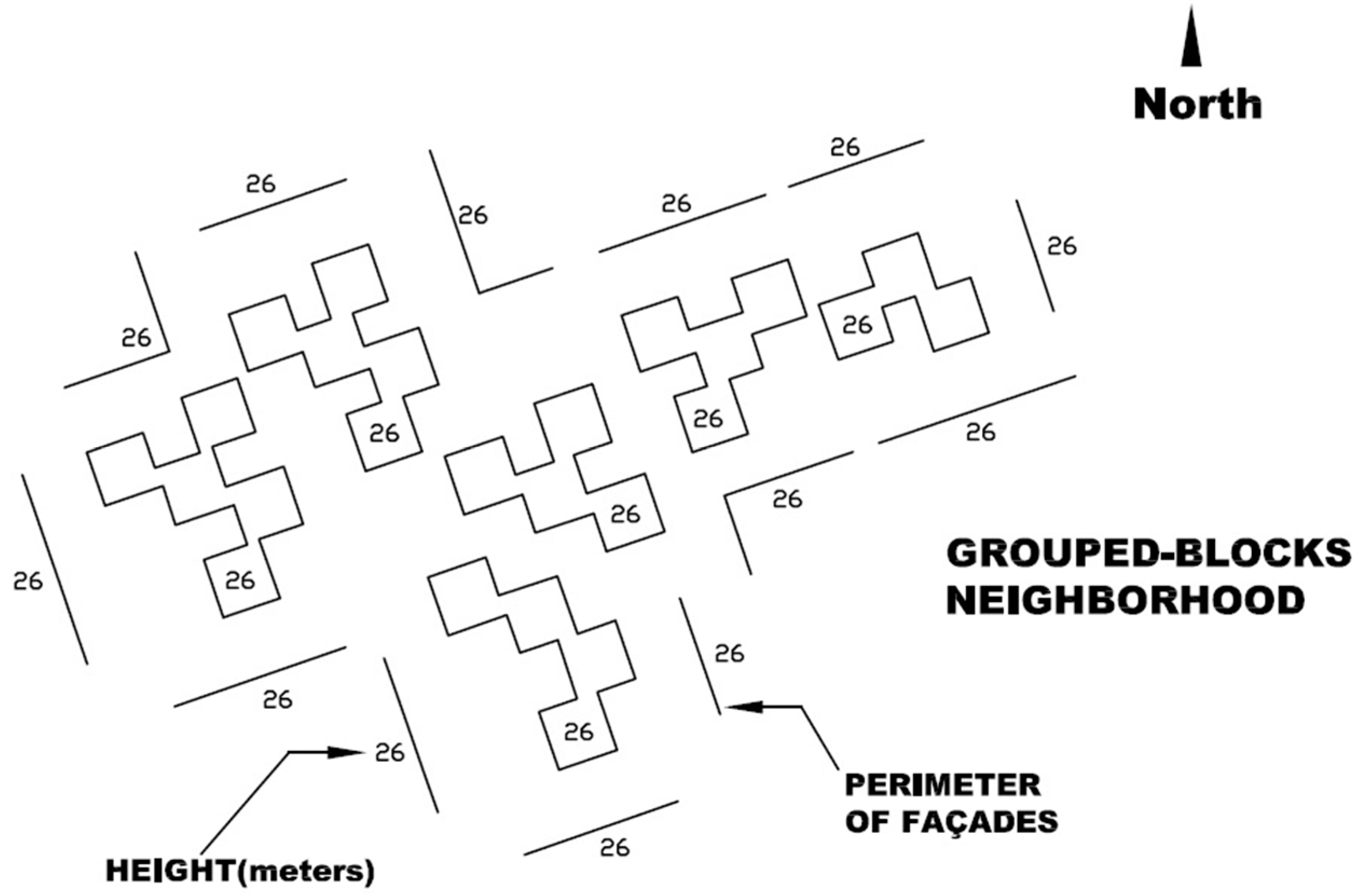
2.2. Case B. Grouped Blocks Neighborhood

Secondly, a neighborhood made up of “grouped blocks” (Figure 4) is considered. This typology of urban planning is often used when the available space is reduced. This usually happens when an old block located in the center of a city is pulled down and a new one is rebuilt in its place. In this context, the roads and the street layout cannot be modified so that the number of dwellings planned will determine the height of the building and its population density.
In this case, the neighborhood selected, B (Figure 5), is situated in a consolidated area of the city of Cordoba (37°52′57.7″ N 4°47′48.3″ W) and it was built in the sixties. The buildings have the maximum height allowed in Cordoba, that is, 7 floors and, consequently, their average height is 25 m [41].
The building configuration used in this neighborhood is the “grouped blocks” with a distribution of attached buildings in which most of the façades are external. The available space between the blocks is used for recreational uses, gardens, etc. This is a common cause of the vertical growth of the city. Figure 6 shows the perimeter and the height of all the buildings of the neighborhood B studied.

3. Methodology

To describe the solar radiation reaching the building façades of a neighborhood and its dependence on the neighborhood typologies, firstly, the level of solar radiation received on different points of the façades of the buildings of each selected neighborhood is determined. For this purpose, a dimensionless factor called Urban Solar Coefficient (USC) is proposed (Equation (1)). This factor is defined as the proportion between the annual average horizontal solar radiation in the neighborhood, H g , a ¯ (in kWh/m2), and the annual average solar radiation reaching a particular point of a façade of the neighborhood, H g , a , p ¯ (in kWh/m2). Thus, the parameter USC represents a measure of the capacity of an urban environment to access the solar resource.
USC = H g , a ¯ H g , a , p ¯
This dimensionless parameter is exclusive for each point of a façade and it represents its solar capacity. Due to the effect of the shadows of neighboring buildings, the level of solar radiation reaching a specific point of a building façade depends on the geometry of the neighborhood (height of the point studied, distance to other façades and so on). Once the USC of each point of each façade has been computed, a statistical analysis of the USC values obtained is developed. From the USC data for the façades of all the buildings of each neighborhood, different regression models have been estimated to determine the dependence of USC on the neighborhood geometry factors. According to this, a simple and accurate empirical mathematical expression for the dependence of USC on the geometry for each neighborhood has been proposed (Equation (2)):
USC ( H , D , θ ) = c 1 · I b + c 2 · H + c 3 · D + c 4 · sin θ + c 5 · cos θ
where:
  • H : Height of the studied point (in meters)
  • D : Distance between the façade studied and the closest one (in meters)
  • θ : Azimuth angle of the selected façade (in degrees)
  • c 1 ,   c 2 ,   c 3 ,   c 4 ,   c 5 : Correlation coefficients. They may be estimated for each neighborhood typology.

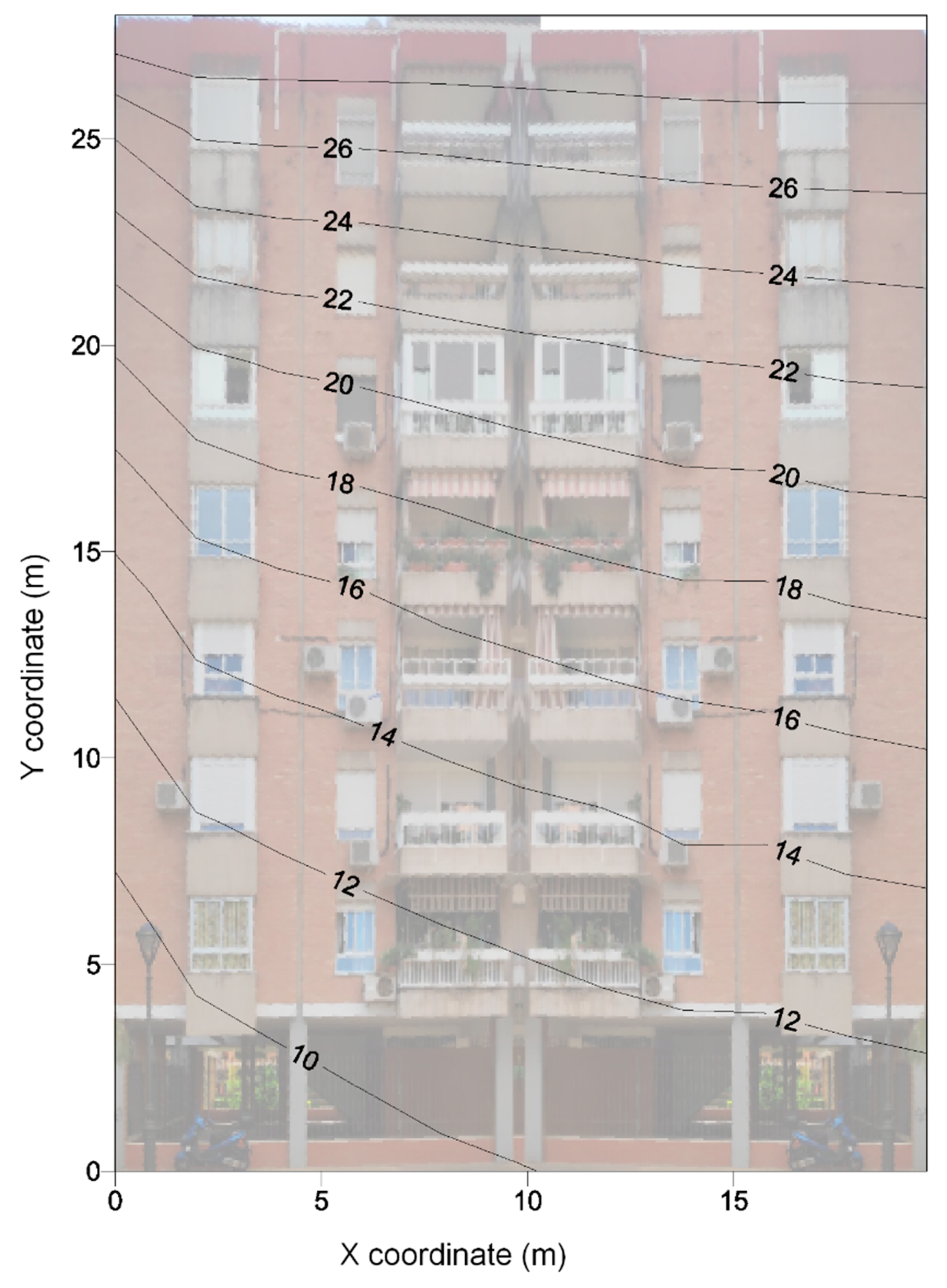
3.1. Solar Radiation Model

In order to obtain the existing correlation, for each typology of neighborhood, between the different variables and the Urban Solar Coefficient (USC) on every point of the façades, the proposed tool uses a specific solar radiation model that considers the three components of the global solar irradiance received on a façade, that is, direct, diffuse and reflected irradiance. Among these three components, global solar irradiance depends mainly on direct irradiance which comes straight from the sun without being scattered. Diffuse irradiance is the solar irradiance reaching the façade after having been scattered from the direct solar beam. Finally, in cities, reflected irradiance, that is, the irradiance reflected by any other surface or façade must also be considered. Its intensity depends on the reflection coefficient or albedo of other surfaces. Thus, the global solar irradiance received on a façade is given by Equation (3).
I = n · s k · s · I b + l + n · k 2 · I d + l n · k 2 · ρ · ( I b + I d )
where:
  • n : Normal vector to the external surface of the façade of the building
  • s : Solar vector
  • k : Normal vector of the tangent plane of the location considered
  • ρ : Albedo
  • I b : Direct irradiance on horizontal surface
  • I d : Diffuse irradiance on horizontal surface
In this solar radiation model, the direct ( I b ) and diffuse ( I d ) irradiances on the horizontal surface have been estimated from synthetic series of data of horizontal global radiation. These series are based on 10-year daily measurements. Thus, global solar radiation for a specific period of time can be determined by integrating, over time, the global irradiance ( I ) on a point given by Equation (3).
However, Equation (3) shows poor results when estimating solar radiation on façades since it does not consider the influence of the height on the diffuse and reflected irradiance. In order to improve this method, a new expression has been developed considering that diffuse and reflected irradiance depends on the portion of sky seen from the studied point. That is, a point with a great height will see a bigger portion of the sky vault and it will receive more diffuse irradiance. On the other hand, a point located close to the floor will see a greater portion of the neighboring buildings so that irradiance reflected from them will be greater. To quantify this behavior, a dimensionless term, called Sky View Factor (SVF) has been defined. It estimates the portion of the celestial vault seen from a specific point [43].
Accordingly, SVF will determine whether the most important component of the global solar irradiance reaching a specific point of a façade will be the diffuse or reflected irradiance (Equation (4)) [44].
I = n · s k · s · I b + S F V · I d + ( 1 S F V ) · ρ · ( I b + I d )

3.2. Software Application for the Analysis

In this paper, the average annual solar radiation on the building façades of two different neighborhoods has been studied. For this purpose, using Equation (4), it is necessary to estimate the solar irradiance received on different points of each façade for all the buildings and both neighborhoods. Specifically, in each façade, 121 points are considered. In addition, each neighborhood is made up of more than 100 façades. Due to the great number of points to analyze, different functions and subroutines in Visual Basic environment have been developed to automatize the calculation. Table 1 lists these subroutines.

3.2.1. Shadow Subroutine

This function determines whether a specific point on the façade of a building is shaded or not. The result will be 0 if the point is shaded and 1 if not.
In order to locate this point, each façade is represented in a local reference system of two orthogonal axis ρ and µ whose values range from 0 to 1 in steps of 0.1 (Figure 7). Thus, in each façade, 121 different points can be studied.
Accordingly, the shadow function uses as input parameters the selected façade and two parameters which indicate the specific point of the façade to be studied. Additionally, other input parameters are the Julian day, the solar time and the latitude of the location of the neighborhood.
To determine whether the point is shaded or lighted, first, its Cartesian coordinates are defined in the global reference system of the city. Then, for the Julian day, latitude and solar time selected, the subroutine will estimate the position of the sun and the straight line from the sun to the façade point of the study. After that, the intersections between this line and the planes representing the neighboring façades will be calculated (Figure 8) by solving the equation system given by Equation (5). Thus, the selected façade point will be shaded if the following conditions are satisfied: a > 1 , 0 < b < 1 and 0 < c < 1 .
( X 0 Y 0 Z 0 ) + a ( S x S y S z ) = ( X 1 Y 1 Z 1 ) + b ( V 12 x   V 12 y V 12 z ) + c ( V 23 x V 23 y V 23 z )
Figure 9 shows the different situations that must be discussed when studying whether the selected point is shaded or not. The output given by the shadow subroutine will be 0 (shadowed point) when there is one intersection point on the façade of an adjacent building (condition 1), when the angle between the normal vector of the external surface of the façade and the solar vector is greater than π/2 rad (condition 2) or when the moment of time considered is before sunrise or after sunset (condition 3). In any other case, the studied point will be lighted and, consequently, the output of the Shadow Function will be 1.

3.2.2. Sky View Factor Subroutine

A shadowed point of a façade will not receive direct solar irradiance, but diffuse or reflected irradiance could reach it. Specifically, the higher the point considered, the greater the portion of the celestial vault seen from it. Thus, the higher points of the façade receive more diffuse irradiance than the lower ones, which will receive more reflected radiation from nearby façades. Since the diffuse component of the solar radiation is greater than the reflected one, the higher points of the façade will receive higher radiation levels.
A new subroutine, called Sky View Factor (SVF), has been developed to simulate this phenomenon. Specifically, for each one of the 121 points considered on a façade, 1012 rays in different directions are generated (Figure 10). For each of them, it determines whether the ray points to the celestial vault or, on the contrary, it reaches the ground or a surrounding building (applying conditions defined in Figure 9). From that analysis, the Sky View Factor (SVF) is defined as the ratio between the number of rays pointing to the celestial vault and the total amount of rays generated. Accordingly, this parameter does not depend on the time but only on the point under consideration and the geometry of the neighborhood selected. In that way, the SVF and its complementary value make it possible to calculate more realistically the diffuse and reflected solar radiation that reaches a point on the façade of a building in a neighborhood considering the obstacles posed by the buildings that surround it.

3.2.3. Instantaneous Irradiance Subroutine

This subroutine estimates the irradiance (W/m2) reaching a specific point of a façade at a solar time using Equation (4) and considering as input data: the façade selected and the coordinates of the point understudy in the local reference system, the latitude, the Julian day, the solar time, the albedo and the solar radiation on a horizontal plane at this latitude and moment of time. Specifically, to simplify the calculation, for the albedo, a mean value of 0.2 has been considered [46].

3.2.4. Daily Solar Radiation Subroutine

From the result of the Instantaneous Irradiance subroutine, this function calculates the daily solar radiation (kWh/m2) for each point of the façade understudy and a Julian day. Specifically, it calculates the irradiance every 6 min throughout each complete day, multiplies the result by 0.1 h and adds all the values of the day obtaining the daily radiation. Accordingly, the result of this function provides valuable information for evaluating the feasibility of a photovoltaic or thermal installation on the façade of a building.
Figure 11 shows the flowchart of the Visual Basic application designed for the calculations.

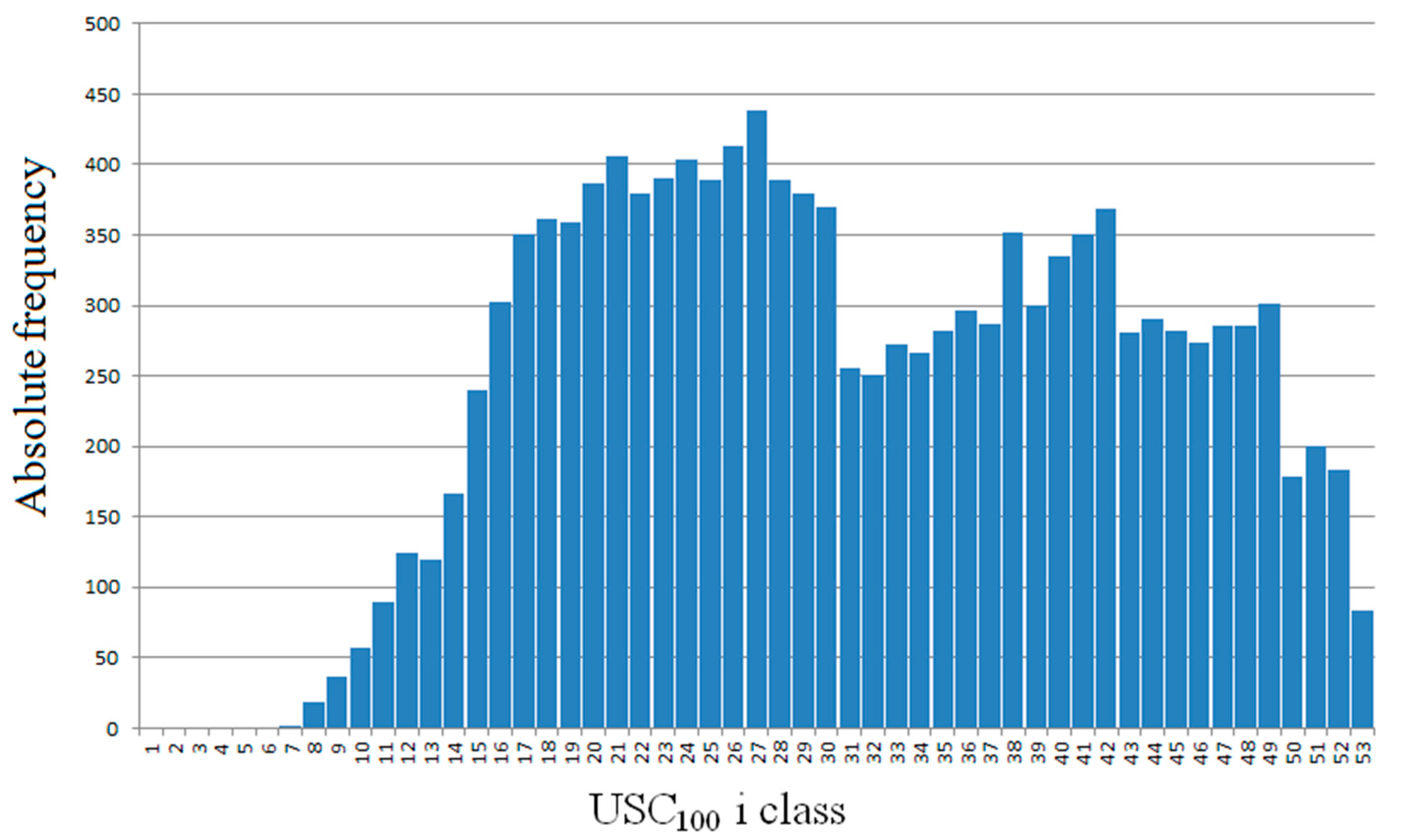
4. Discussion and Regressions

As explained before, the USC value has been calculated for the 121 points considered (Figure 7) on each façade of neighborhoods A and B. Specifically, 14,036 USC values for neighborhood A and 13,673 USC values for neighborhood B have been obtained. To simplify the graphical representation and visualization of the data, an auxiliary variable, USC100, is defined according to Equation (6).
USC 100 = 100 · USC
Figure 12 shows the USC100 absolute frequency histogram for neighborhood A. For this representation, consecutive classes of index i have been defined so that i meets Equation (7).
i 1 < USC 100 i
This condition is equivalent to define i according to Equation (8).
i = integer ( USC 100 ) + 1
Thus, as an example, if USC = 0.341, it will belong to class 35.
Similarly, Figure 13 shows the USC 100 absolute frequency histogram for neighborhood B.
Figure 12 shows a displacement of USC values in neighborhood A with respect to values in neighborhood B (Figure 13), which implies better access to solar resources in neighborhood A in general. This effect is linked to the lower height of the buildings in neighborhood A, as well as to the distribution in a simpler geometry. The intertwined geometry of neighborhood B favors the existence of north-facing walls that are also obstructed in all directions. Normally the lowest points of this type of façades are associated with the lowest values of the USC index. In both neighborhoods, as expected, the maximum USC values are reached at the highest points of the façades that are best oriented to the south and have a low level of obstruction. The value of the maximums of USC is slightly higher in neighborhood B, which could be explained by the greater height of the buildings and their better South orientation.
Table 2 shows the values of the descriptive statistics of USC for both distributions, from which significant differences in the mean and the median have been observed. Both parameters indicate that access to the solar resource is about 20% higher in neighborhood A than in neighborhood B.
The exposed methodology also allows mapping the USC100 variable in façades. This enables us to deepen the details of the differences in access to the solar resource at each point of the same façade. Figure 14 and Figure 15 show the variability of USC100 in representative façades of neighborhoods A and B respectively. They also allow quantifying, in specific façades, the dependence of the USC100 gradient on the height. It is worth highlighting that in the façades analyzed, the increase of this gradient is greater on the highest points than on the lowest ones. This behavior is more evident as the height of the building increases.
Finally, with the USC data of all the façades and buildings, a regression analysis has been performed for each neighborhood in order to analyze the variables with the most significant influence on the USC value.
Studying the influence of façade facing, street width and height of the studied point on the outcome of the USC factor at each point studied, linear regression is proposed (Equation (9)).
USC ( H , D , θ ) = c 1 + c 2 · H + c 3 · D + c 4 · cos θ
where:
  • H : Height of the studied point over the ground (in meters)
  • D : Street width (in meters)
  • θ : Façade facing (in grades)
  • c 1 , c 2 , c 3 , c 4 : Constants
Equation (10) shows the result of the regression for neighborhood A. It is observed that the height of the studied point over the floor and the street width keep a direct relationship with the USC factor while in the case of the cosine of the orientation of the façade is reversed. Its correlation coefficient has a value of 0.919.
USC ( H , D , θ ) = 0.197 + 0.012 · H + 0.001 · D 0.115 · cos   θ
On the other hand, the regression for neighborhood B (Equation (11)) has a correlation value of 0.86 which is lower than the value obtained for neighborhood A. In this case, as in the previous one, the influence of the height of the point considered and the street width is direct and the orientation of the façade reverse.
USC ( H , D , θ ) = 0.074 + 0.010 · H + 0.002 · D 0.091 · cos   θ
These regressions allow knowing the value of the USC factor, and therefore the annual radiation received at any point on the façade was chosen, knowing only the typology of the neighborhood and the annual radiation on a horizontal surface.

5. Conclusions

In this paper, a novel model for calculating the solar radiation that reaches the façade of a building in a complex neighborhood is presented. The equation proposed allows obtaining accurate results for the irradiance, considering how the position of the adjacent buildings affects to the diffuse and reflected irradiance received on the façade. For this purpose, the Sky View Factor (SVF) is calculated. Considering the obstacles posed by surrounding buildings, it represents the portion of celestial vault viewed from each point of the façade. Accordingly, the SVF depends on the position of the point on the façade of the building but remains constant as long as the geometry of the neighborhood is not altered.
Four subroutines, programmed in Visual Basic Excel environment, have been developed to solve the problem of shading, the quantification of the obstacles seen, and the radiation received on a complete façade. Therefore, these subroutines allow the calculation of the solar radiation reaching any point of a selected façade of a neighborhood. From it, it is possible to display the results of the radiation on the façade in an intuitive way, through a solar radiation contour map.
The model and the program created have been used to characterize two typologically different neighborhoods through their capacity for solar energy harnessing. To this aim, the Urban Solar Coefficient (USC) has been defined, relating the annual radiation on horizontal surface of the study area and the annual radiation received at a chosen point on a façade. Calculating this factor on 121 points on each façade and for all the façades compounding the neighborhood, the distribution of the USC values for each neighborhood and the two different histograms that characterize the radiation according to the urban typology have been obtained. A comparative statistical analysis of the USC data for each neighborhood shows that the maximum values of USC are registered in neighborhood B (0.540) since its buildings are higher than the ones in neighborhood A, with a relative maximum USC value of 0.528. On the contrary, the relative minimum value in neighborhood A (0.063) is higher than in neighborhood B (0.012) due to the fact that the geometry of the neighborhood A is simpler, and its buildings are lower and more separated which reduces the effect of obstacles. On the whole, the mean value is higher in neighborhood A (0.317) than in neighborhood B (0.260) which implies the best access to solar resources in the first area than in the second one.
Finally, with the results obtained, one regression for each neighborhood has been proposed to determine the dependence of USC on the geometry of the buildings. These regressions allow calculating easily the amount of radiation received on the points of the façades, in neighborhoods that meet the characteristics described in this paper. In this way, the methodology and the tool proposed provide the calculation of the solar irradiance incident on any point of the façade of a given neighborhood. However, the tool presents some limitations and it is planned to be improved in upcoming works with the inclusion of a new subroutine that represents, in 3D contour maps, the values of irradiance in all the facades of the buildings of a certain neighborhood. Likewise, a network of sensors is being designed to automatically monitor the experimental irradiance received on a given façade in order to validate the methodology and tool proposed in this work.
Despite these limitations, the methodology and tool proposed could be very useful, among other applications, to plan urban designs of new neighborhoods that guarantee the solar rights and favor an optimum harnessing of the solar resource, whether for natural lighting or for the generation of energy from renewable sources, which will have a positive impact on the sustainability of cities.

Author Contributions

Conceptualization, L.M.F.-A. and R.L.-L.; methodology, J.R.-F. and M.V.-M.; software, A.M.-G.; validation, L.M.F.-A. and M.V.-M.; formal analysis, L.M.F.-A., J.R.-F. and R.L.-L.; bibliographic search, L.M.F.-A. and M.V.-M.; data curation, J.R.-F. and R.L.-L.; writing—original draft preparation, L.M.F.-A., A.M.-G. and M.V.-M.; writing—review & editing, L.M.F.-A., J.R.-F., R.L.-L. and M.V.-M.; supervision, J.R.-F. and R.L.-L.

Funding

This research received no external funding.

Conflicts of Interest

The authors declare no conflict of interest.

References

  1. United Nations. World Population Prospects 2019 (Report). Available online: https://population.un.org/wpp/Publications/Files/WPP2019_Highlights.pdf (accessed on 18 September 2019).
  2. Eremia, M.; Toma, L.; Sanduleac, M. The smart city concept in the 21st century. Procedia Eng. 2017, 181, 12–19. [Google Scholar] [CrossRef]
  3. Milošević, M.R.; Milošević, D.M.; Stević, D.M.; Stanojević, A.D. Smart city: Modeling key indicators in Serbia using IT2FS. Sustainability 2019, 11, 3536. [Google Scholar] [CrossRef]
  4. United Nations. World Urbanization Prospects 2018 (Report). Available online: https://population.un.org/wup/Publications/Files/WUP2018-Report.pdf (accessed on 18 September 2019).
  5. Sandman, H.; Levänen, J.; Savela, N. Using empathic design as a tool for urban sustainability in low-resource settings. Sustainability 2018, 10, 2493. [Google Scholar] [CrossRef]
  6. Martos, A.; Pacheco-Torres, R.; Ordóñez, J.; Jadraque-Gago, E. Towards successful environmental performance of sustainable cities: Intervening sectors. A review. Renew. Sustain. Energy Rev. 2016, 57, 479–495. [Google Scholar] [CrossRef]
  7. Lindfors, A.; Feiz, R.; Eklund, M.; Ammenberg, J. Assessing the potential, performance and feasibility of urban solutions: methodological considerations and learnings from biogas solutions. Sustainability 2019, 11, 3756. [Google Scholar] [CrossRef]
  8. Alamdari, P.; Nematollahi, O.; Alemrajabi, A.A. Solar energy potentials in Iran: A review. Renew. Sustain. Energy Rev. 2013, 21, 778–788. [Google Scholar] [CrossRef]
  9. Mardonova, M.; Choi, Y. Assessment of photovoltaic potential of mining sites in Uzbekistan. Sustainability 2019, 11, 2988. [Google Scholar] [CrossRef]
  10. Østergaard, P.A.; Duic, N.; Noorollahi, Y.; Mikulcic, H.; Kalogirou, S. Sustainable development using renewable energy technology. Renew. Energy 2020, 146, 2430–2437. [Google Scholar] [CrossRef]
  11. Panwar, N.L.; Kaushik, S.C.; Kothari, S. Role of renewable energy sources in environmental protection: A review. Renew. Sustain. Energy Rev. 2011, 15, 1513–1524. [Google Scholar] [CrossRef]
  12. Belakehal, A.; Tabet Aoul, K.; Bennadji, A. Sunlighting and daylighting strategies in the traditional urban spaces and buildings of the hot arid regions. Renew. Energy 2004, 29, 687–702. [Google Scholar] [CrossRef]
  13. Glaeser, E.L.; Kahn, M.E. Sprawl and urban growth. Handb. Reg. Urban Econ. 2004, 4, 2481–2527. [Google Scholar]
  14. Van Esch, M.M.E.; Looman, R.H.J.; De Bruin-Hordijk, G.J. The effects of urban and building design parameters on solar access to the urban canyon and the potential for direct passive solar heating strategies. Energy Build. 2012, 47, 189–200. [Google Scholar] [CrossRef]
  15. Drif, M.; Pérez, P.J.; Aguilera, J.; Aguilar, J.D. A new estimation method of irradiance on a partially shaded PV generator in grid-connected photovoltaic systems. Renew. Energy 2008, 33, 2048–2056. [Google Scholar] [CrossRef]
  16. Zhang, X.; Wei, Z. A hybrid model based on principal component analysis, wavelet transform, and extreme learning machine optimized by Bat algorithm for daily solar radiation forecasting. Sustainability 2019, 11, 4138. [Google Scholar] [CrossRef]
  17. Alzoubi, H.H.; Alshboul, A.A. Low energy architecture and solar rights: Restructuring urban regulations, view from Jordan. Renew. Energy 2010, 35, 333–342. [Google Scholar] [CrossRef]
  18. Edwards, L.; Torcellini, P. A Literature Review of the Effects of Natural Light on Building Occupants. Available online: https://www.nrel.gov/docs/fy02osti/30769.pdf (accessed on 18 September 2019).
  19. Calama-González, C.; León-Rodríguez, Á.; Suárez, R. Daylighting and energy performance evaluation of an egg-crate device for hospital building retrofitting in a Mediterranean climate. Sustainability 2018, 10, 2714. [Google Scholar] [CrossRef]
  20. Ihm, P.; Nemri, A.; Krarti, M. Estimation of lighting energy savings from daylighting. Build. Environ. 2009, 44, 509–514. [Google Scholar] [CrossRef]
  21. Gago, E.J.; Muneer, T.; Knez, M.; Köster, H. Natural light controls and guides in buildings. Energy saving for electrical lighting, reduction of cooling load. Renew. Sustain. Energy Rev. 2015, 41, 1–13. [Google Scholar] [CrossRef]
  22. Torres-Roldán, M.; López-Luque, R.; Varo-Martínez, M. Design of an innovative and simplified polar heliostat for integration in buildings and urban environments. Sol. Energy 2015, 119, 159–168. [Google Scholar] [CrossRef]
  23. Torres-Roldán, M.; López-Luque, R.; Varo-Martínez, M. Assessment of the pointing error of heliostats with a single not polar rotation axis for urban applications. Sol. Energy 2016, 137, 281–289. [Google Scholar] [CrossRef]
  24. Spacek, A.D.; Neto, J.M.; Biléssimo, L.D.; Junior, O.H.A.; Neto, G.P.D.F.; Giansella, R.D.S.; De Santana, M.V.F.; Malfatti, C.D.F. Proposal for an experimental methodology for evaluation of natural lighting systems applied in buildings. Energies 2017, 10, 1014. [Google Scholar] [CrossRef]
  25. Polo, M.-E.; Pozo, M.; Quirós, E. Directional statistics in solar potential of rooftops at three different neighborhoods of a medium size city. Proceedings 2018, 2, 1275. [Google Scholar] [CrossRef]
  26. Gómez-Munoz, V.M.; Porta-Gándara, M.A. General model to build awnings and external walls with optimum shading interaction. Renew. Energy 2004, 29, 605–613. [Google Scholar] [CrossRef]
  27. Smith, G.B. Materials and systems for efficient lighting and delivery of daylight. Sol. Energy Mater. Sol. Cells 2004, 84, 395–409. [Google Scholar] [CrossRef]
  28. Kanters, J.; Horvat, M.; Dubois, M.C. Tools and methods used by architects for solar design. Energy Build. 2014, 68, 721–731. [Google Scholar] [CrossRef]
  29. Brito, M.C.; Freitas, S.; Guimarães, S.; Catita, C.; Redweik, P. The importance of facades for the solar PV potential of a Mediterranean city using LiDAR data. Renew. Energy 2017, 111, 85–94. [Google Scholar] [CrossRef]
  30. Bayón-Cueli, C.; Barbón, A.; Bayón, L.; Barbón, N. A cost-energy based methodology for small-scale linear Fresnel reflectors on flat roofs of urban buildings. Renew. Energy 2020, 146, 944–959. [Google Scholar] [CrossRef]
  31. Mingfang, T. Solar control for buildings. Build. Environ. 2002, 37, 659–664. [Google Scholar] [CrossRef]
  32. Salazar Trujillo, J.H. Solar performance and shadow behaviour in buildings. Case study with computer modelling of a building in Loranca, Spain. Build. Environ. 1998, 33, 117–130. [Google Scholar] [CrossRef]
  33. Gómez-Muñoz, V.M.; Porta-Gándara, M.A.; Fernández, J.L. Effect of tree shades in urban planning in hot-arid climatic regions. Landsc. Urban Plan. 2010, 94, 149–157. [Google Scholar] [CrossRef]
  34. Shao, J. Calculation of sunshine duration and saving of land use in urban building design. Energy Build. 1990, 15, 407–415. [Google Scholar] [CrossRef]
  35. La Gennusa, M.; Lascari, G.; Rizzo, G.; Scaccianoce, G.; Sorrentino, G. A model for predicting the potential diffusion of solar energy systems in complex urban environments. Energy Policy 2011, 39, 5335–5343. [Google Scholar] [CrossRef]
  36. Abd Alla, S.; Bianco, V.; Tagliafico, L.A.; Scarpa, F. An innovative approach to local solar energy planning in Riva Trigoso, Italy. J. Build. Eng. 2020, 27, 100968. [Google Scholar] [CrossRef]
  37. Mardaljevic, J.; Rylatt, M. Irradiation mapping of complex urban environments: An image-based approach. Energy Build. 2003, 35, 27–35. [Google Scholar] [CrossRef]
  38. Gadsden, S.; Rylatt, M.; Lomas, K.; Robinson, D. Predicting the urban solar fraction: A methodology for energy advisers and planners based on GIS. Energy Build. 2003, 35, 37–48. [Google Scholar] [CrossRef]
  39. Antaluca, E.; Merino, L.; Beckers, B. Correlation between Measured and Calculated Solar Radiation Data in Compiègne, France. Available online: http://www.worldses.org/journals/environment/environment-2010.htm (accessed on 18 September 2019).
  40. Miguet, F. A Further Step in Environment and Bioclimatic Analysis: The Software Tool Solene. Available online: http://www.ibpsa.org/proceedings/BS2007/p126_final.pdf (accessed on 18 September 2019).
  41. Ayuntamiento de Córdoba (Spain) Plan General de Ordenación Urbanística (PGOU). Available online: http://www.gmucordoba.es/urbanismo/plan-general-de-ordenacion-urbanistica-pgou (accessed on 7 November 2019).
  42. Instituto de Estadística y Cartografía de Andalucía. Distribución Espacial de la Población en Andalucía. Available online: http://www.juntadeandalucia.es/institutodeestadisticaycartografia/distribucionpob/index.htm (accessed on 7 November 2019).
  43. Ramírez-Faz, J.; López-Luque, R.; Casares, F.J. Development of synthetic hemispheric projections suitable for assessing the sky view factor on vertical planes. Renew. Energy 2015, 74, 279–286. [Google Scholar] [CrossRef]
  44. Fernández-Ahumada, L.M.; Casares, F.J.; Ramírez-Faz, J.; López-Luque, R. Mathematical study of the movement of solar tracking systems based on rational models. Sol. Energy 2017, 150, 20–29. [Google Scholar] [CrossRef]
  45. Márquez-García, A.; Varo-Martínez, M.; López-Luque, R. Solar Energy in Urban Environments: A New Solar Radiation Model for the Analysis of Energy on Façades; LAP Lambert Academic Publishing: Alemania, Germany, 2013. [Google Scholar]
  46. Duffie, J.A.; Beckman, W.A. Solar Engineering of Thermal Processes: Fourth Edition; John Wiley and Sons: Hoboken, NJ, USA, 2013. [Google Scholar]
Figure 1. L-Shaped and U-Shaped blocks.
Sustainability 11 06596 g001
Figure 2. 3D view of a U-shaped and L-shaped neighborhood (Case A) of Cordoba (Spain).
Sustainability 11 06596 g002
Figure 3. Perimeter and heights of the buildings of a U-shaped and L-shaped block neighborhood (Case A) of Cordoba (Spain).
Sustainability 11 06596 g003
Figure 4. Grouped blocks.
Sustainability 11 06596 g004
Figure 5. 3D view of a grouped block neighborhood (Case B) of Cordoba (Spain).
Sustainability 11 06596 g005
Figure 6. Perimeter and heights of the buildings of a grouped block neighborhood (Case B) of Cordoba (Spain).
Sustainability 11 06596 g006
Figure 7. Grid façade representation.
Sustainability 11 06596 g007
Figure 8. Representation of the geometric problem.
Sustainability 11 06596 g008
Figure 9. Representation of the shading conditions.
Sustainability 11 06596 g009
Figure 10. Generation of the rays on the selected point. Adapted from [45].
Sustainability 11 06596 g010
Figure 11. Flowchart of the Visual Basic application developed.
Sustainability 11 06596 g011
Figure 12. USC100 (Urban Solar Coefficient) histogram for neighborhood A.
Sustainability 11 06596 g012
Figure 13. USC100 histogram for neighborhood B.
Sustainability 11 06596 g013
Figure 14. USC100 map for a representative façade of neighborhood A.
Sustainability 11 06596 g014
Figure 15. USC100 map for a representative façade of neighborhood B.
Sustainability 11 06596 g015
Table 1. Summary of subroutines developed.
Name of SubroutineFeatures
ShadowIt takes the value 0 if the point is Shaded and 1 if it is lighted
Sky View FactorPortion of the sky seen from the point [0–0.5]
Daily RadiationEnergy in kWh/ m2 with a 6 min integration interval
IrradianceMeasure of the irradiance in W/m2 on the point
Table 2. Descriptive statistic values for USC in both neighborhoods.
Descriptive Statistic ValuesNeighborhood ANeighborhood B
N sample14,03613,673
Minimum0.0630.012
Maximum0.5280.540
Average0.3170.260
Median0.3040.249
Variance0.0130.017
Standard Deviation0.1160.132

