Influence of Evacuation Walkway Design Parameters on Passenger Evacuation Time along Elevated Rail Transit Lines Using a Multi-Agent Simulation


Abstract
1. Introduction
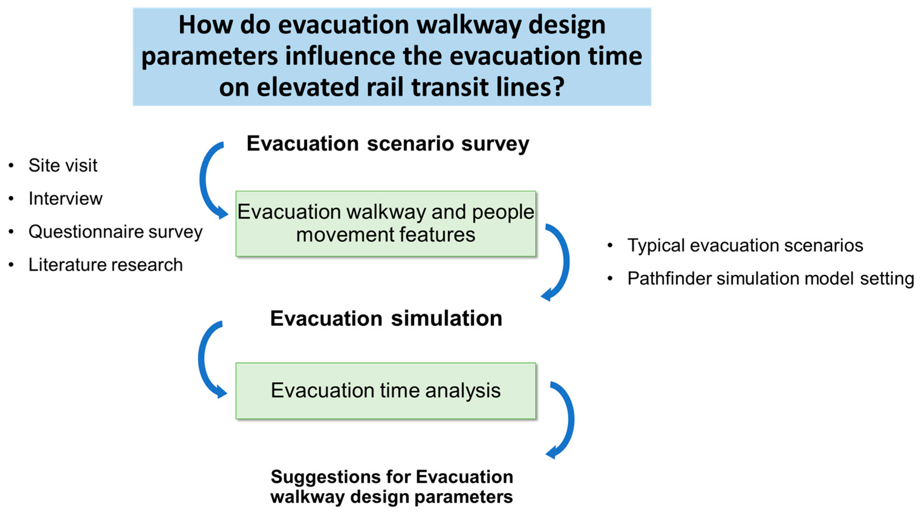
2. Methodology
2.1. Evacuation Scenario Survey
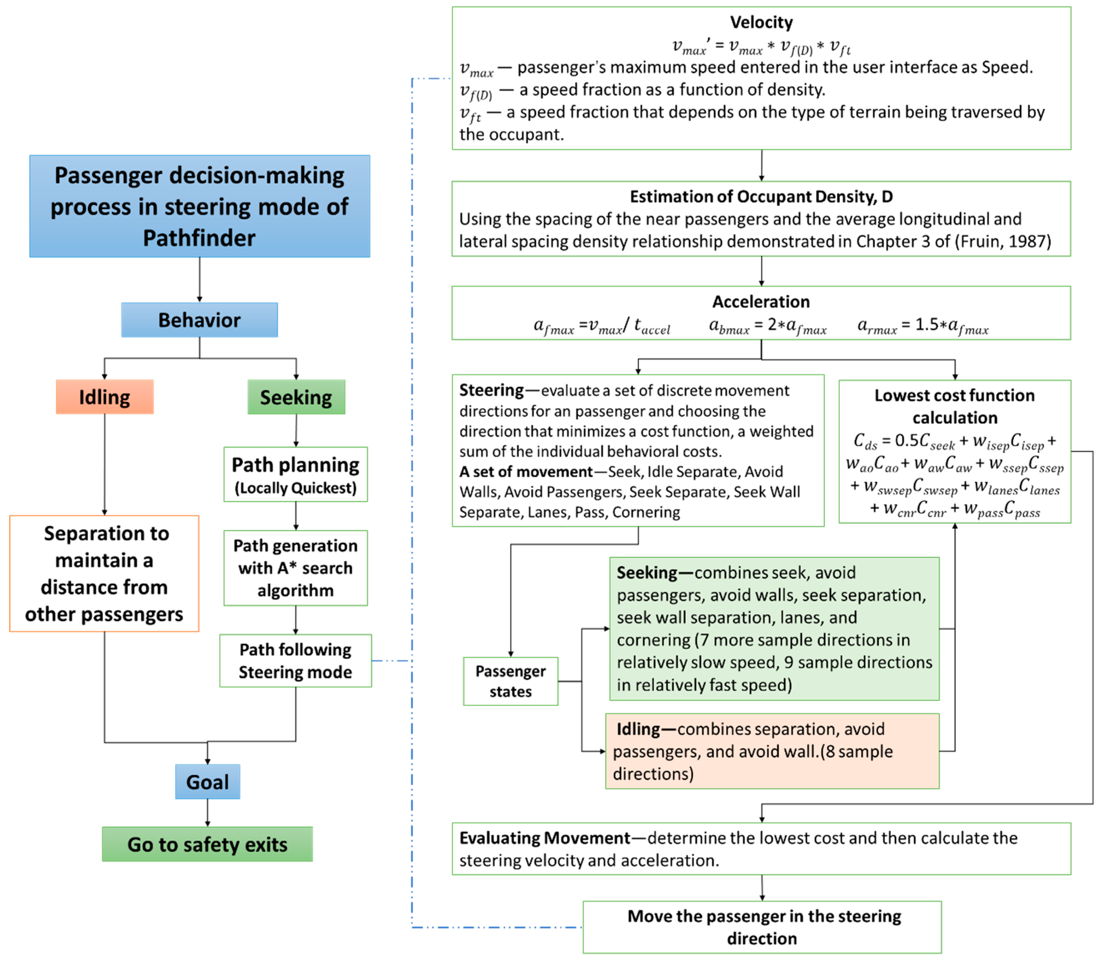
2.2. Multi-Agent Evacuation Simulation
2.2.1. Model Basis
2.2.2. Evacuation Time Measurement
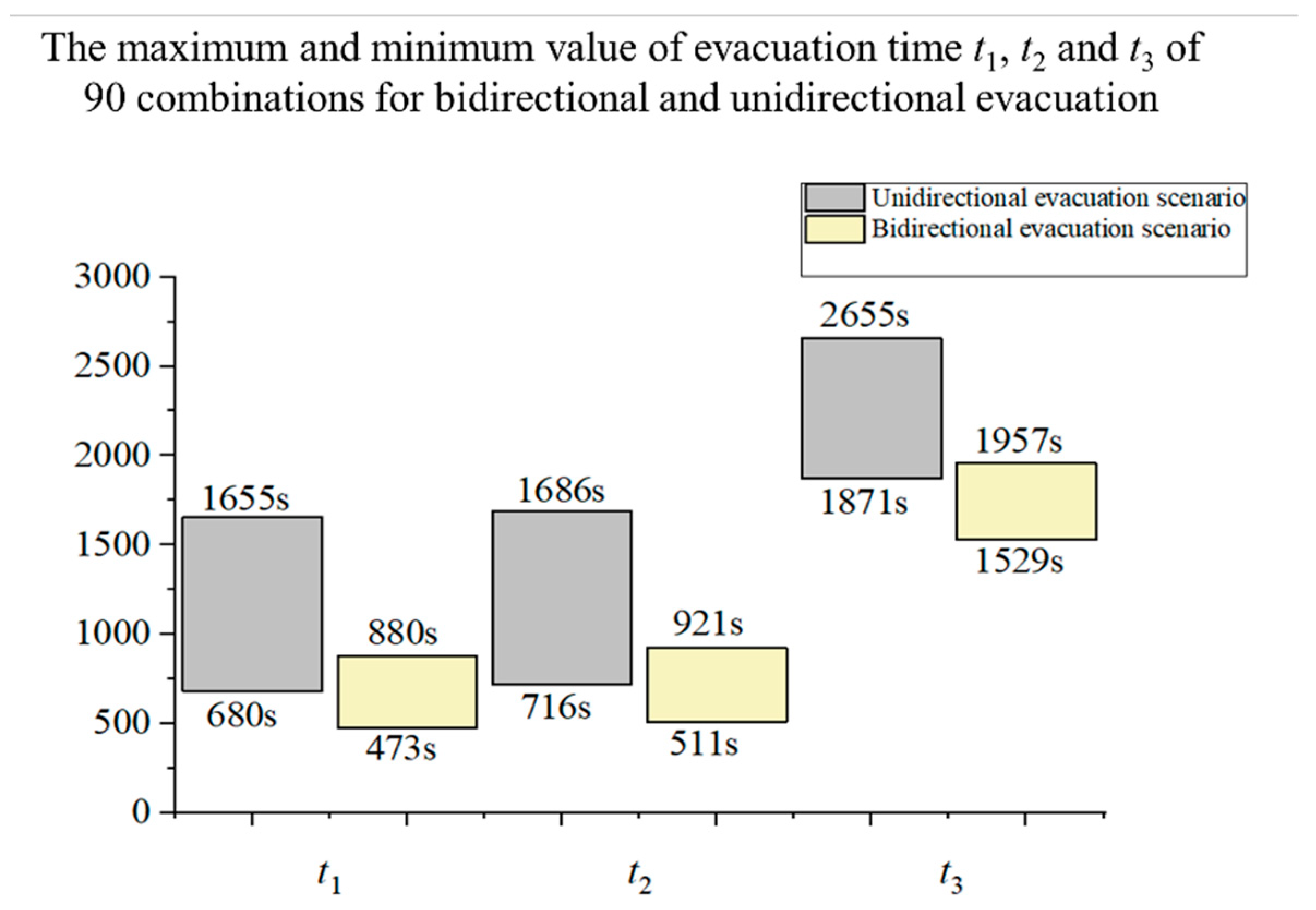
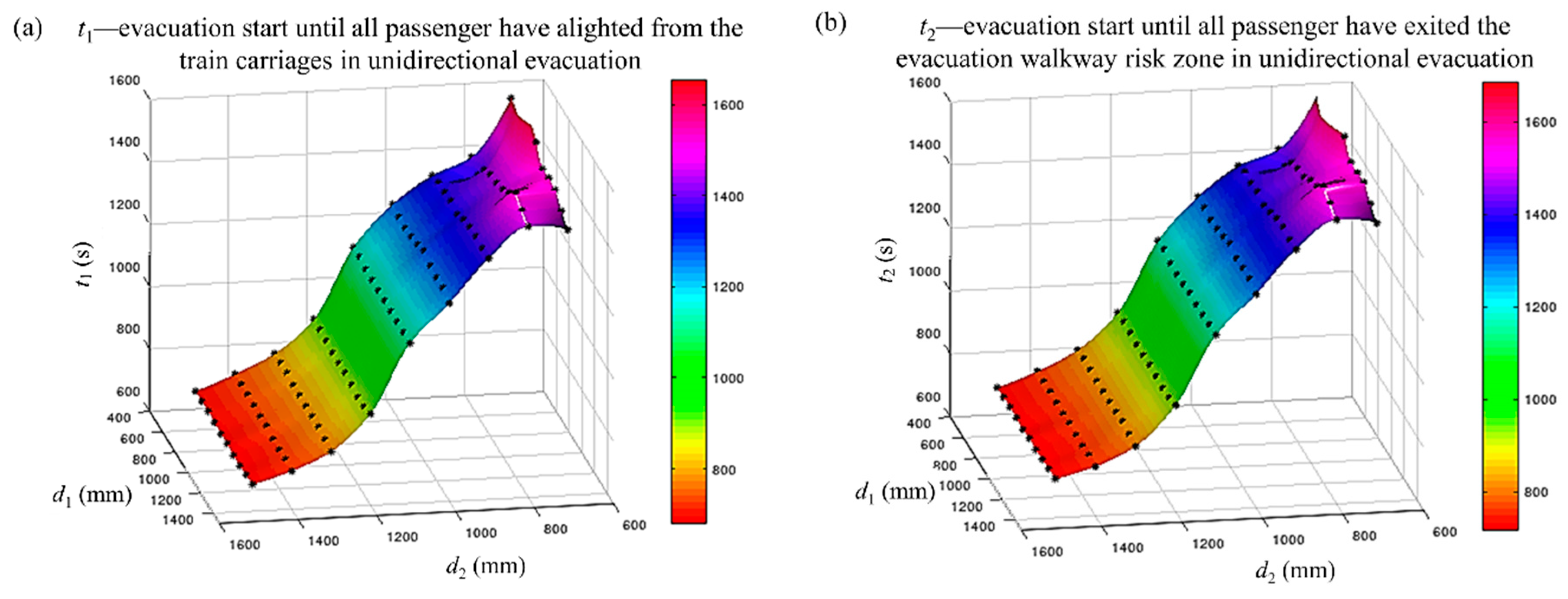
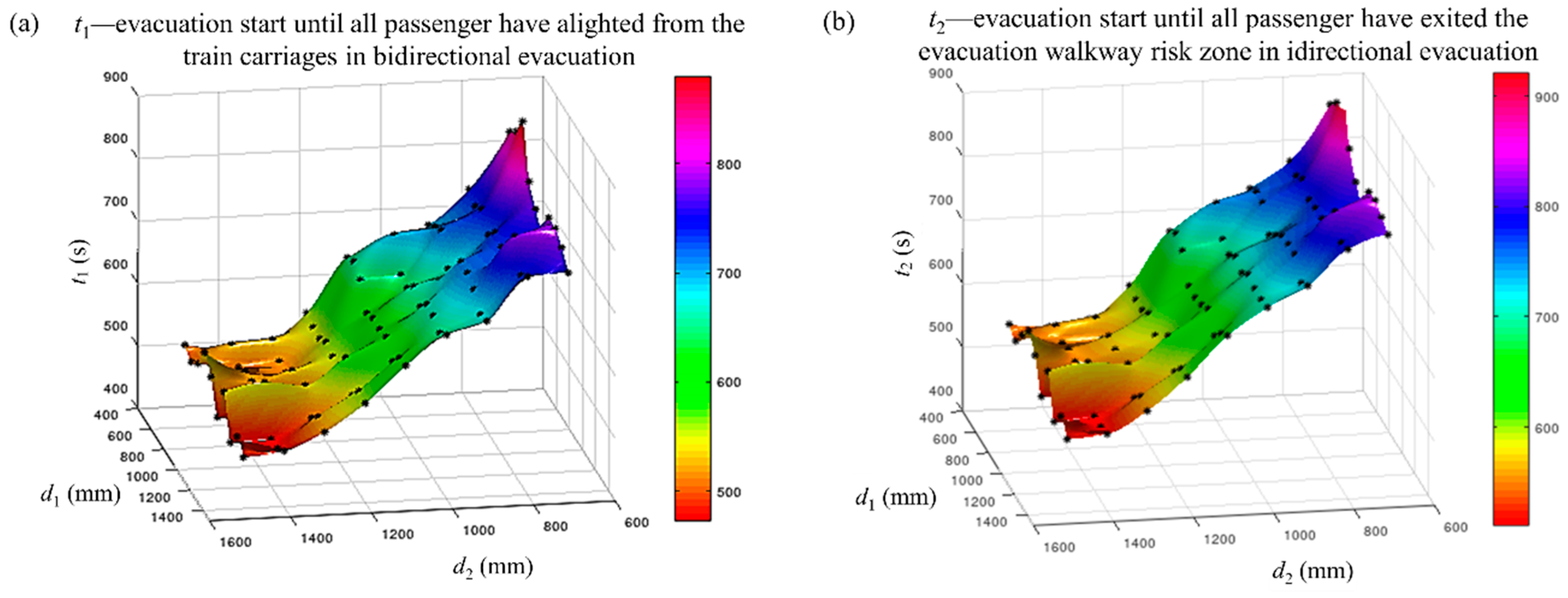
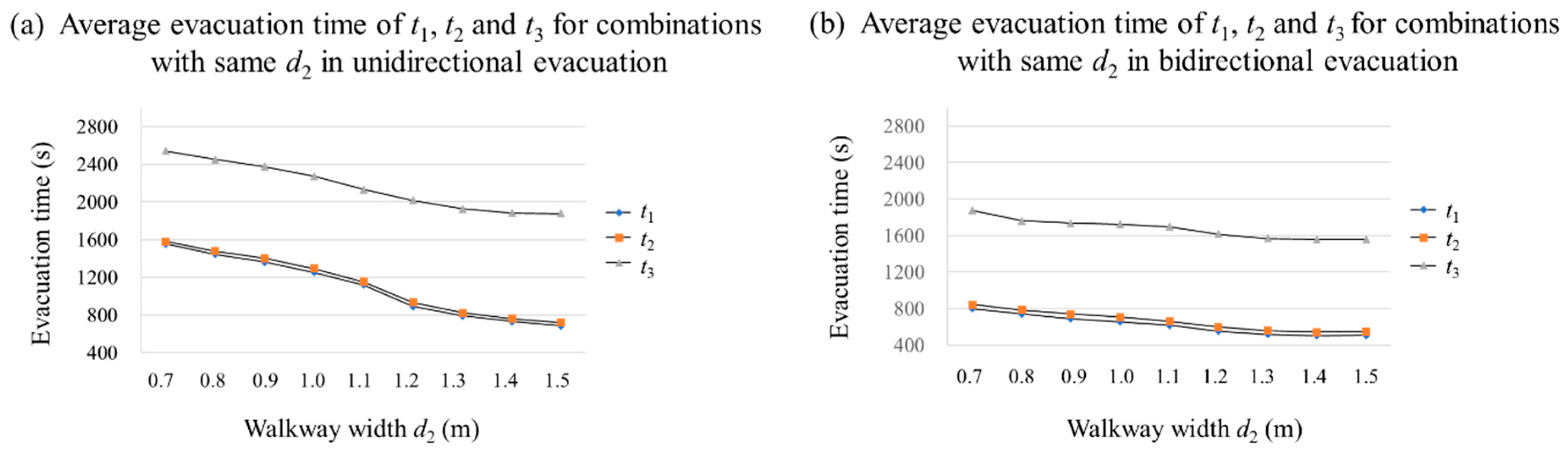
- t1—evacuation time, until all passengers have alighted from the train carriages.
- t2—evacuation time, until all passengers have exited the evacuation walkway risk zone. The total length of the risk zone is the sum of the total length of the train and the fire separation length on both sides of the train—16.5 + 89 + 16.5 = 132 m. The fire separation length is 16.5 m, which is >12 m, as required by the Fire Prevention Standard for Building Design of China [38].
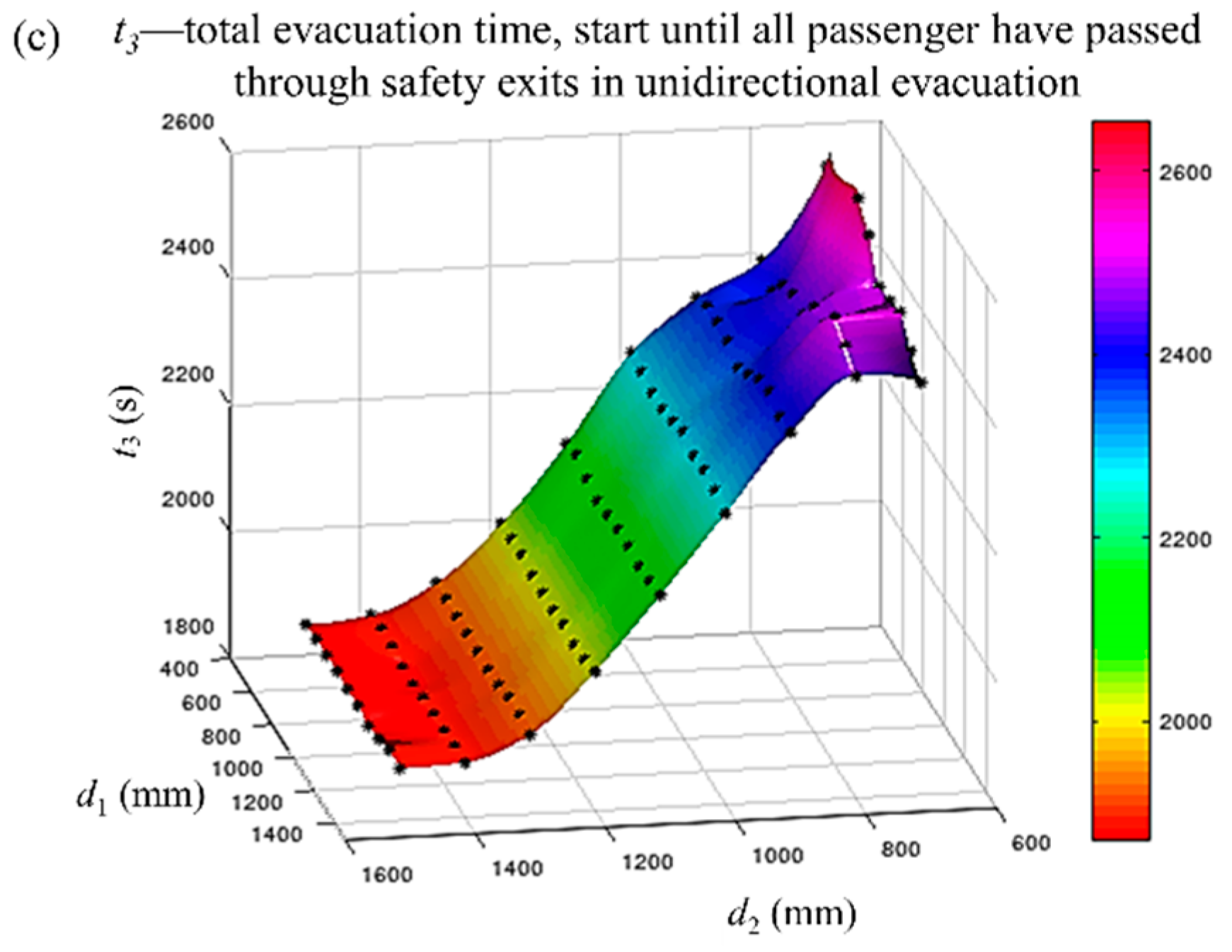
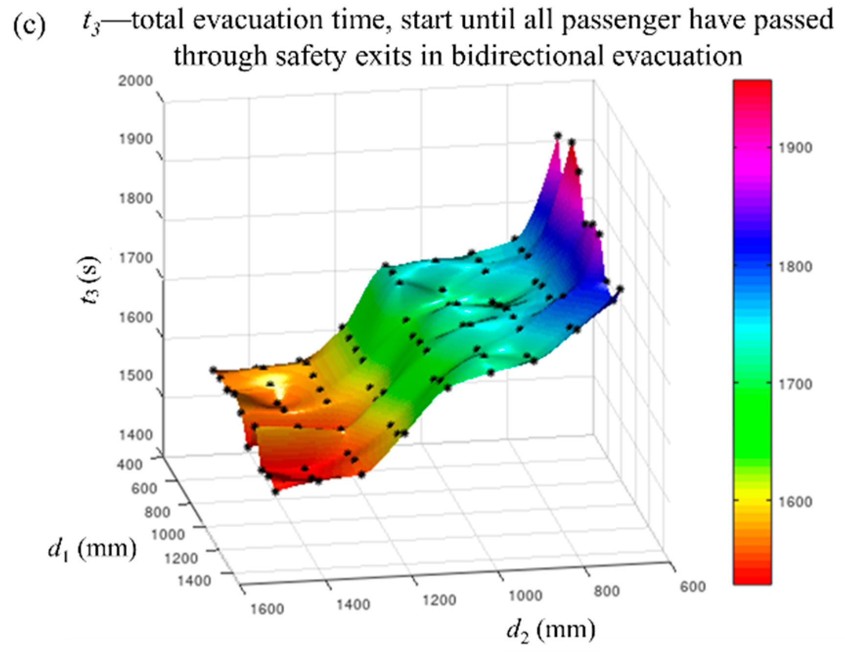
- t3—total evacuation time start, until all passengers have passed through the safety exits.
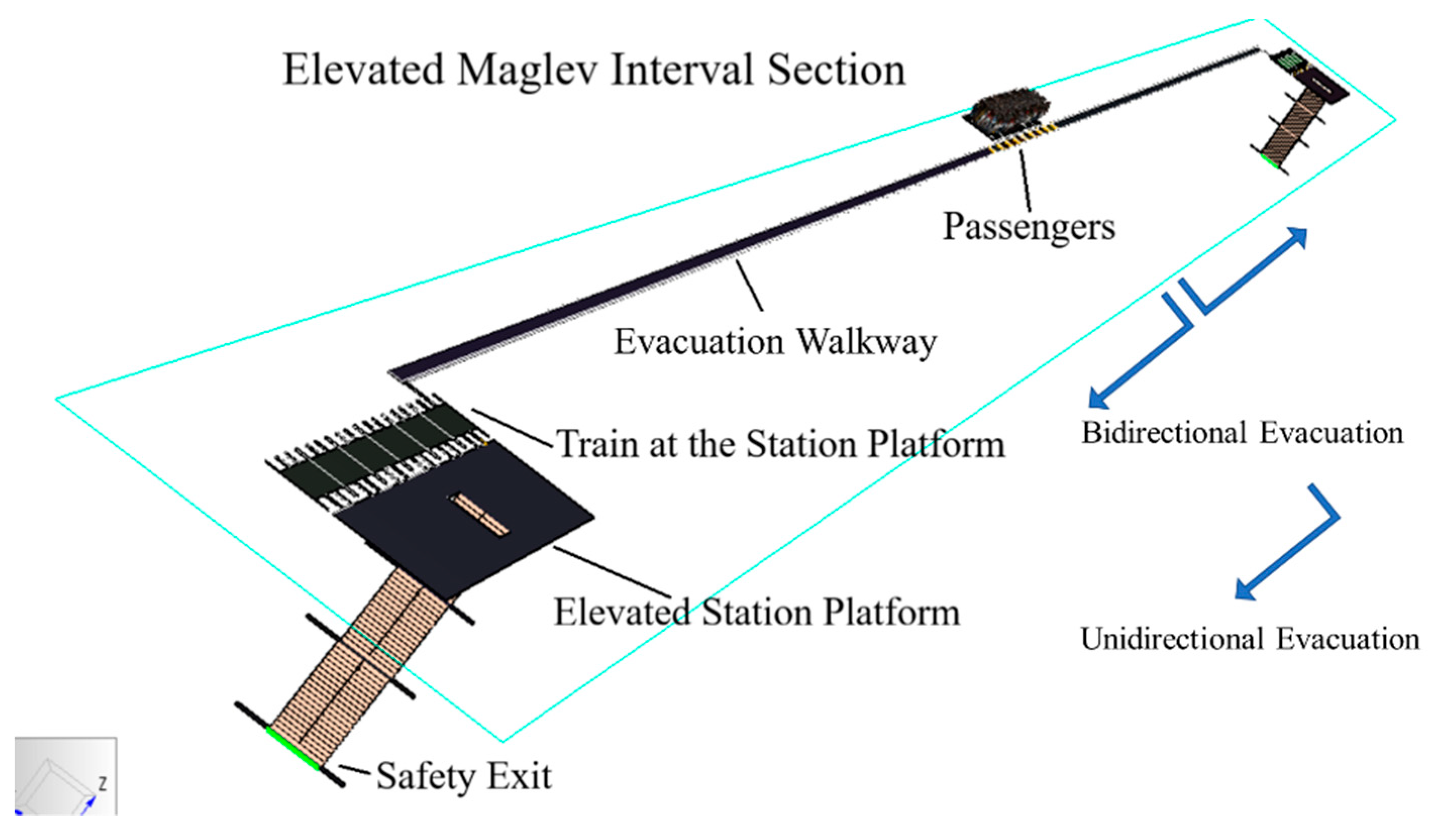
2.2.3. Simulation Setting
3. Results
3.1. Number of Iterations for the Simulation
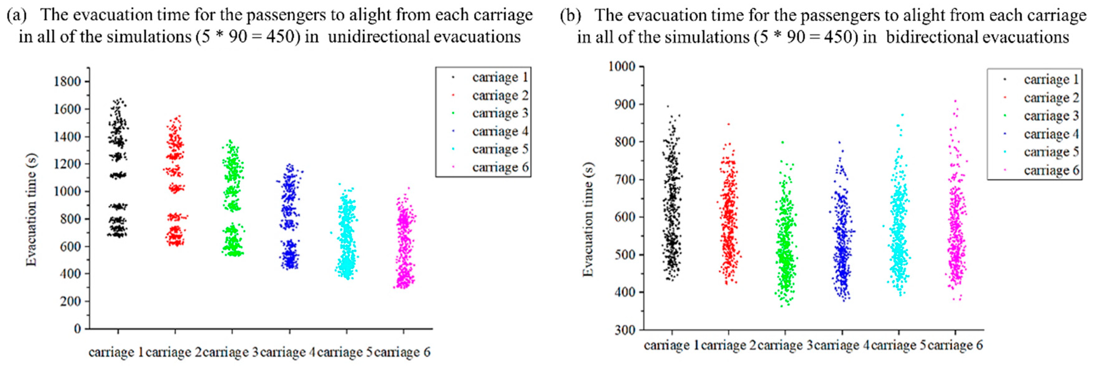
3.2. Bidirectional vs. Unidirectional
3.3. Evacuation Time vs. Walkway Width and Entrance Width
3.3.1. In Unidirectional Evacuation
3.3.2. In Bidirectional Evacuation
4. Discussion
4.1. The Combined Effect of the Entrance Width and Walkway Width on the Evacuation Time
4.2. Simulation Results Compared to Empirical Formula Results
4.3. Suggestions for Evacuation Walkway Parameter Design
- Only one simulation setting, namely, evacuation in the middle of an interval section on an elevated transit line was considered. This setting considered the most likely worst-case scenario during an emergency on an elevated transit line, i.e., with the longest walking distance on both sides to safety exits. In a highly unlikely event, a train might stop close to the station, but only one-way escape is available. This study has also partly covered unidirectional evacuation up to point t2 but will have a different t3.
- The total number of evacuation passengers was not set as a variable, but only a maximum number of 1032 is used. This is assumed to be the worst-case evacuation scenario, as fewer people would result in a less chaotic situation. Six carriage marshalling, with a 1032 passenger capacity, was considered in this study, because it is the current maximum passenger capacity and maximum carriage marshalling for a Maglev train operation. The number of carriages and passengers can be set as variable as longer trains might be anticipated in the future.
5. Conclusions
Author Contributions
Funding
Acknowledgments
Conflicts of Interest
References
- Xue, H.; Yang, P.; Zhang, H.; Jing, E. Study on the Control Strategy of Urban Rail Transit Passenger Flow under the Condition of Large Passenger Flow. IOP Conf. Ser. Earth Environ. Sci. 2019, 234, 012001. [Google Scholar] [CrossRef]
- Burnett, J. Fire Safety Concerns for Rail Rapid Transit Systems. Fire Saf. J. 1984, 8, 3–7. [Google Scholar] [CrossRef]
- Kyriakidis, M.; Hirsch, R.; Majumdar, A. Metro Railway Safety: An Analysis of Accident Precursors. Saf. Sci. 2012, 50, 1535–1548. [Google Scholar] [CrossRef]
- Gershon, R.R.M.; Qureshi, K.A.; Barrera, M.A.; Erwin, M.J.; Goldsmith, F. Health and Safety Hazards Associated with Subways: A Review. J. Urban Health 2005, 82, 10–20. [Google Scholar] [CrossRef]
- Ouyang, M.; Hong, L.; Yu, M.-H.; Fei, Q. STAMP-based Analysis on the Railway Accident and Accident Spreading: Taking the China–Jiaoji Railway Accident for Example. Saf. Sci. 2010, 48, 544–555. [Google Scholar] [CrossRef]
- Akabal, F.M.; Masirin, M.I.H.M.; Akasah, Z.A.; Rohani, M.M. Review on Selection and Suitability of Rail Transit Station Design Pertaining to public safety. In Proceedings of the IOP Conference Series: Materials Science and Engineering, Melaka, Malasia, 6–7 May 2017; Volume 226, p. 012033. [Google Scholar]
- Vuilleumier, F.; Weatherill, A.; Crausaz, B. Safety aspects of railway and road tunnel: Example of the Lötschberg railway tunnel and Mont-Blanc road tunnel-ScienceDirect. Tunn. Undergr. Space Technol. 2002, 17, 153–158. [Google Scholar] [CrossRef]
- Cheng, H.; Yang, X. Emergency Evacuation Capacity of Subway Stations. Procedia Soc. Behav. Sci. 2012, 43, 339–348. [Google Scholar] [CrossRef]
- Hunter-Zaworski, K. Analysis of Passenger Incident Data from Five Rail Transit Systems. Safety 2017, 3, 21. [Google Scholar] [CrossRef]
- Lombardi, M.; Cuarascio, M.; Rossi, G. The Management of Uncertainty: Model for Human Error Probability in Railway System. Am. J. Appl. Sci. 2014, 11, 381–390. [Google Scholar] [CrossRef]
- Seike, M.; Kawabata, N.; Hasegawa, M. Experiments of Evacuation Speed in Smoke-filled Tunnel. Tunn. Undergr. Space Technol. 2016, 53, 61–67. [Google Scholar] [CrossRef]
- Benn, J. Railway Bridge Failure during Flooding in the UK and Ireland. Proc. Inst. Civ. Eng. Forensic Eng. 2013, 166, 163–170. [Google Scholar] [CrossRef]
- Kucera, P.; Bradáčová, I. Modelling the Evacuation of People from a Train on Fire in a Railway Tunnel. In Recent Advances in Engineering. 3rd European Conference of Chemical and Civil Engineering; Angrey, D., Catarina, L.C., Eds.; WSEAS Press: Paris, France, 2012; pp. 196–201. [Google Scholar]
- Chen, S.-K.; Li, S.-Y.; Li, X.; Hong, J.; Lai, J.-X.; Cai, P. Modeling Evacuation Time for Passengers from Metro Platforms. J. Transp. Syst. Eng. Inf. Technol. 2008, 8, 101–107. [Google Scholar]
- Li, Y.; Liu, S. Passenger Evacuation in Subway Transit Tunnels Installed with Side Evacuation Platforms. Urban Rapid Rail Transit 2007, 20, 13–16. [Google Scholar]
- Zhai, W.; Zhao, C. Dynamics of Maglev Vehicle/Guidway Systems(Ⅰ)-Magnet/Rail Interaction and System Stability. Chin. J. Mech. Eng. 2005, 41, 1–10. [Google Scholar] [CrossRef]
- Fitting Out The Railway. Available online: http://www.crossrail.co.uk/construction/railway-systems/ (accessed on 24 September 2019).
- Habicht, A.T.; Braaksma, J.P. Effective Width of Pedestrian Corridors. J. Transp. Eng. 1984, 110, 80–93. [Google Scholar] [CrossRef]
- Lundström, F.V.; Ahlfont, J.; Nilsson, D. The Effect of Raised Walkway Design on Evacuation Behaviour in Rail Tunnels. Fire Saf. Sci. 2014, 11, 1091–1102. [Google Scholar] [CrossRef]
- European Commision. Commision Decision of 20 December 2007. Concerning the Technical Specification of Interoperability Relating to ‘Safety in Railway Tunnels’ in the Trans-European Conventional and High-Speed Rail System. 2008. Available online: https://eur-lex.europa.eu/LexUriServ/LexUriServ.do?uri=CONSLEG:2008D0163:20130124:EN:PDF (accessed on 31 October 2019).
- Standardization Administration of the People’s Republic of China. Code for Design of Metro; Standardization Administration of the People’s Republic of China: Beijing, China, 2013; pp. 26–27. [Google Scholar]
- Minishty of Housing and Urban-Rural Developement of the People’s Republic of China. Code for Design of Medium and Low Speed Maglev Transit; Minishty of Housing and Urban-Rural Developement of the People’s Republic of China: Beijing, China, 2017.
- Helbing, D.; Farkas, I.J.; Molnar, P.; Vicsek, T. Simulation of pedestrian crowds in normal and evacuation situations. Pedestr. Evacuation Dyn. 2002, 21, 21–58. [Google Scholar]
- Fridolf, K.; Nilsson, D.; Frantzich, H. The flow rate of people during train evacuation in rail tunnels: Effects of different train exit configurations-ScienceDirect. Saf. Sci. 2014, 62, 515–529. [Google Scholar] [CrossRef]
- Cuesta, A.; Abreu, O.; Balboa, A.; Alvear, D. An experimental data-set on merging flows in rail tunnel evacuation. Tunn. Undergr. Space Technol. 2017, 70, 155–165. [Google Scholar] [CrossRef]
- Railway Bureau; Ministry of Land, Infrastructure, Transport and Tourism. Technical Regulatory Standards on Japanese Railways; Railway Bureau; Ministry of Land, Infrastructure, Transport and Tourism: Tokyo, Japan, 2012; p. 196.
- Reynolds, C.W. Steering behaviors for autonomous characters. In Proceedings of the Game Developers Conference, San Jose, CA, USA, 15–19 March 1999; Volume 1999, pp. 763–782. [Google Scholar]
- Heni, A.; Jan, M.; Oliver, O. Fast, Neat, and Under Control: Arbitrating Between Steering Behaviors. AI Game Program. Wisdom 2006, 3, 221–232. [Google Scholar]
- Thornton, C.; O’Konski, R.; Hardeman, B.; Swenson, D. Pathfinder: An Agent-Based Egress Simulator. In Pedestrian and Evacuation Dynamics; Peacock, R.D., Kuligowski, E.D., Averill, J.D., Eds.; 2011; pp. 889–892. [Google Scholar]
- Thornton, C.; O’Konski, R.; Klein, B.; Hardeman, B.; Swenson, D. New Wayfinding Techniques in Pathfinder and Supporting Research. In Pedestrian and Evacuation Dynamics 2012; Weidmann, U., Kirsch, U., Schreckenberg, M., Eds.; Springer International Publishing: Berlin/Heidelberg, Germany, 2014; pp. 1315–1322. [Google Scholar]
- Thunderhead Engineering. Technical Reference of Pathfinder. Available online: https://www.thunderheadeng.com/pathfinder/resources/ (accessed on 28 September 2019).
- Thunderhead Engineering. Pathfinder Vertification and Validation. Available online: https://www.thunderheadeng.com/pathfinder-verification-validation-archive/ (accessed on 28 September 2019).
- Ronchi, E.; Colonna, P.; Capote, J.; Alvear, D.; Berloco, N.; Cuesta, A. The Evaluation of Different Evacuation Models for Assessing Road Tunnel Safety Analysis. Tunn. Undergr. Space Technol. 2012, 30, 74–84. [Google Scholar] [CrossRef]
- Wang, H.; Chen, Q.; Yan, J.; Yuan, Z.; Liang, D. Emergency Guidance Evacuation in Fire Scene Based on Pathfinder. In Proceedings of the 2014 7th International Conference on Intelligent Computation Technology and Automation, Changsha, China, 25–26 October 2014; pp. 226–230. [Google Scholar]
- White, N.; Dowling, V.P.; Barnett, J.R. Full-scale Fire Experiment On A Typical Passenger Train. Fire Saf. Sci. 2005, 8, 1157–1168. [Google Scholar] [CrossRef]
- Chiam, B.H. Numerical Simulation of a Metro Train Fire. Master’s Thesis, University of Canterbury: Christchurch, Canterbury, New Zealand, 2005. [Google Scholar]
- Linteris, G.T.; Rafferty, I.P. Flame size, heat release, and smoke points in materials flammability. Fire Saf. J. 2008, 43, 442–450. [Google Scholar] [CrossRef]
- Minishty of Housing and Urban-Rural Developement of the People’s Republic of China. Code for Fire Protection Design of Buildings; Minishty of Housing and Urban-Rural Developement of the People’s Republic of China: Beijing, China, 2018.
- Wenting, L. Research on Passengers Capacity of Emergency Evacuation in Subway. Master’s Thesis, Tongji University, Shanghai, China, 2008. [Google Scholar]
- Research on Emergency Evacuation Behaviour of Passengers in Subway Station Fire. Master’s Thesis, Hunan University of Science and Technology, Hunan, China, 2012.
- Hurley, M.J.; Gottuk, D.T.; Hall, J.R., Jr.; Harada, K.; Kuligowski, E.D.; Puchovsky, M.; Watts, J.M., Jr.; WIECZOREK, C.J. SFPE Handbook of Fire Protection Engineering; Springer: Berlin/Heidelberg, Germany, 2015; ISBN 978-1-4939-2565-0. [Google Scholar]
- Standardization Administration of the People’s Republic of China. Code for Safety Evacuation of Metro; Standardization Administration of the People’s Republic of China: Beijing, China, 2017; pp. 8–10. [Google Scholar]


| Item | Content | ||||
|---|---|---|---|---|---|
| Line type | Elevated EMS Maglev transit | ||||
| Marshalling | Six carriages | ||||
| Length of each carriage | 16.5 m | ||||
| Door number of each carriage | Two | ||||
| Train door width | 1.4 m | ||||
| Location of evacuation walkway | Parallel with the accident train | ||||
| Location of the evacuation walkway entrances | Aligned with carriage doors | ||||
| Location of the safety exits | One level below the track at the station | ||||
| Number of safety exits | Two | ||||
| Interval section length | 1500 m | ||||
| Station platform length | 100 m | ||||
| Distance to safety exits | 850 m | ||||
| Number of staircases in each station | One | ||||
| Staircase width | 2.4 m | ||||
| Connection between the evacuation walkway and the train |  | ||||
| Evacuation walkway entrance width, d1 (m), vector | 0.5 | 0.6 | 0.7 | 0.8 | 0.9 |
| 1.0 | 1.1 | 1.2 | 1.3 | 1.4 | |
| Evacuation walkway width, d2 (m), vector | 0.7 | 0.8 | 0.9 | 1.0 | 1.1 |
| 1.2 | 1.3 | 1.4 | 1.5 | — | |
| Group | Age | Percentage | Shoulder Width | Moving Speed |
|---|---|---|---|---|
| Children | ≤15 | 9% | 0.4 m | 0.78 m/s |
| Young person | 16–35 | 65% | 0.46 m | 1.22 m/s |
| Middle-aged person | 36–55 | 23% | 0.46 m | 1.17 m/s |
| Elderly people | ≥56 | 3% | 0.46 m | 0.75 m/s |
| Total number of passengers | 1032 | |||
| Moving speed modification factor | 0.75 | |||
| Pre-action time | Uniform distribution on [30 s,120 s] | |||
| The moving mode in Pathfinder | Steering | |||
| Case No. | d1 and d2 Combination | Average Value of t3 (s) for a Different Number of Iterations K | The Mean Value of the Total Evacuation Time with a Different K | ||
|---|---|---|---|---|---|
| T(K=5) (s) | T(K=50) (s) | ||||
| 1 | d1 = 0.5 m d2 = 0.7 m |  | 1929.4 | 1925.3 | −0.21% |
| 2 | d1 = 0.9 m d2 = 1.1 m |  | 1669.6 | 1671.5 | 0.11% |
| 3 | d1 = 1.4 m d2 = 1.5 m |  | 1522.3 | 1524.8 | 0.16% |
| Evacuation Walkway Width d2 (m) | Tpre-a (min) | Ttr (min) | Empirical Formula | Simulation | ||||
|---|---|---|---|---|---|---|---|---|
| Tpass (min) | Ttotal = Tpre-a + Ttr + Tpass (min) | Average of Total Evacuation Time, t3 (min) | ||||||
| Unidirectional | Bidirectional | Unidirectional | Bidirectional | Unidirectional | Bidirectional | |||
| 0.7 | 2 | 24.6 | 19.6 | 16.2 | 41.3 | 37.9 | 42.4 | 31.3 |
| 0.8 | 2 | 21.5 | 19.6 | 16.2 | 38.8 | 35.4 | 40.9 | 29.4 |
| 0.9 | 2 | 19.1 | 19.6 | 16.2 | 36.9 | 33.5 | 39.6 | 28.9 |
| 1.0 | 2 | 17.2 | 19.6 | 16.2 | 35.4 | 32.0 | 37.9 | 28.7 |
| 1.1 | 2 | 15.6 | 19.6 | 16.2 | 34.1 | 30.7 | 35.6 | 28.3 |
| 1.2 | 2 | 14.3 | 19.6 | 16.2 | 33.1 | 29.7 | 33.6 | 26.9 |
| 1.3 | 2 | 13.2 | 19.6 | 16.2 | 32.2 | 28.8 | 32.1 | 26.1 |
| 1.4 | 2 | 12.3 | 19.6 | 16.2 | 31.5 | 28.1 | 31.4 | 26.0 |
| 1.5 | 2 | 11.5 | 19.6 | 16.2 | 30.8 | 27.4 | 31.3 | 26.0 |
| Evacuation Walkway Width, d2 (m) | Unidirectional Evacuation | Bidirectional Evacuation | ||
|---|---|---|---|---|
| Entrance Width, d1 (m) | The Minimum Value of t2 (s) | Entrance Width, d1 (m) | The Minimum Value of t2 (s) | |
| 0.7 | 1.4 | 1485 | 1.0 | 791 |
| 0.8 | 0.6 | 1411 | 0.8 | 772 |
| 0.9 | 0.5 | 1386 | 0.8 | 720 |
| 1.0 | 1.4 | 1278 | 0.8 | 692 |
| 1.1 | 0.8 | 1151 | 1.2 | 633 |
| 1.2 | 1.2 | 927 | 1.0 | 577 |
| 1.3 | 1.4 | 814 | 1 | 531 |
| 1.4 | 1.4 | 756 | 1.2 | 516 |
| 1.5 | 0.9 | 717 | 1.2 | 511 |
© 2019 by the authors. Licensee MDPI, Basel, Switzerland. This article is an open access article distributed under the terms and conditions of the Creative Commons Attribution (CC BY) license (http://creativecommons.org/licenses/by/4.0/).
Share and Cite
Pan, Z.; Wei, Q.; Torp, O.; Lau, A. Influence of Evacuation Walkway Design Parameters on Passenger Evacuation Time along Elevated Rail Transit Lines Using a Multi-Agent Simulation. Sustainability 2019, 11, 6049. https://doi.org/10.3390/su11216049
Pan Z, Wei Q, Torp O, Lau A. Influence of Evacuation Walkway Design Parameters on Passenger Evacuation Time along Elevated Rail Transit Lines Using a Multi-Agent Simulation. Sustainability. 2019; 11(21):6049. https://doi.org/10.3390/su11216049
Chicago/Turabian StylePan, Zihua, Qingchao Wei, Olav Torp, and Albert Lau. 2019. "Influence of Evacuation Walkway Design Parameters on Passenger Evacuation Time along Elevated Rail Transit Lines Using a Multi-Agent Simulation" Sustainability 11, no. 21: 6049. https://doi.org/10.3390/su11216049
APA StylePan, Z., Wei, Q., Torp, O., & Lau, A. (2019). Influence of Evacuation Walkway Design Parameters on Passenger Evacuation Time along Elevated Rail Transit Lines Using a Multi-Agent Simulation. Sustainability, 11(21), 6049. https://doi.org/10.3390/su11216049