Article

Mitigation Strategies for Reduction of Embodied Energy and Carbon, in the Construction Systems of Contemporary Quality Architecture

Department of Civil Engineering, University of Salerno, 84084 Fisciano (SA), Italy
*
Author to whom correspondence should be addressed.
Sustainability 2019, 11(14), 3806; https://doi.org/10.3390/su11143806
Submission received: 5 June 2019 / Revised: 5 July 2019 / Accepted: 8 July 2019 / Published: 11 July 2019
(This article belongs to the Special Issue Building Energy Assessment)

Abstract

:
The criticality related to the consumption of operational energy and related greenhouse gas (GHG) emissions of existing buildings is clearly decreasing in new buildings due to the strategies tested and applied in recent years in the energy retrofit sector. Recently, studies have been focusing on strategies to reduce environmental impacts related to the entire life cycle of the building organism, with reference to the reduction of embodied energy (and related greenhouse gas emissions) in building materials. As part of EEA’s European EBC project, Annex 57, a wide range of case studies have been promoted with the aim of identifying design strategies that can reduce the embodied energy and related greenhouse gas emissions of buildings. The aim of this paper is to investigate the most common construction systems in the construction industry (concrete, steel, wood) through the analysis of three contemporary architectural works, with the aim of identifying the predisposition for environmental sustainability of each technological system, thus guiding the operators in the sector towards design choices more compatible with the environmental requirements recommended by European legislation.

1. Introduction

The construction industry requires the extraction of large quantities of materials, resulting in the consumption of energy resources and the release of pollutant emissions into the atmosphere. The side effects of energy production and consumption have led to uncertainty in terms of the residual availability of non-renewable resources, resulting in potential environmental risks, both at national, regional and local level [1]. The estimates indicate that 75% of currently available resources in developed countries in 2050 are expected to be used. These data show that the strategy of reducing the operational energy of the real estate stock, pursued through the construction of more performing buildings, has not been sufficient to trigger an effective reversal of the current trend. This highlights, also in the perspective of Energy Efficiency Directive (2012/27/EU, amended by the EU Directive 2018/844), the need to boost the market for renovation of existing buildings. Member States should renovate at least 3% of their building stock through retrofitting and, where necessary, demolition and reconstruction [2]. In the past, only operational energy was considered in life cycle analyses due to its higher energy incidence in the overall life-cycle. However, the growth of energy-efficient equipment and systems, in combination with more advanced and effective insulation materials, has allowed a portion of operational energy to be contained. However, the reduction in operating costs has led to an increase in the costs associated with the other phases of the life cycle of building materials [3,4,5,6,7,8] (Figure 1). Crawford and Treloar [9] stated that the embodied energy contained in a building in Australia was 20–50 times the annual operating energy required for the building. Pacheco-Torgal et al. [10] quantified the influence of operational energy compared to embodied energy in 97 apartment buildings in Portugal, in accordance with the first directive on energy performance of buildings—2002/91/EC-EPBD (re-casted by directive 2010/31/EU-EPDB on energy performance; the latter, amended by the EU Directive 2018/844 on energy efficiency). The operational energy in today’s buildings was on average 187.2 MJ/m2/year and the embodied energy represented approximately 2372 MJ/m2, or approximately 25.3% of the first for a useful life of 50 years. The sharp decrease in operational energy due to the implementation of the EPBD means that the total energy needed for the production of building materials, the embodied energy, could represent almost 400% of operational energy in the near future. In addition, the authors propose that replacing up to 75% of Portland cement with mineral additives could provide the energy savings needed to operate a highly efficient building for 50 years. A study by Thormark [11] showed that embodied energy was 40% of the total energy needed for a life expectancy of 50 years. However, through the replacement of materials, embodied energy could be reduced by approximately 17%. The following graph (Figure 1) shows the trend of the relationship between operational energy and embedded energy inversely proportional and over time [12].
In the construction sector, energy and related pollutant emissions are embodied or associated with individual construction materials. Embodied energy (hereinafter EE) is considered as the amount of energy needed at all stages of the product’s life cycle, from the cradle to the grave.
To establish its magnitude, the international scientific standard requires methodologies capable of estimating the total energy used within the entire life cycle of a building through the contribution of the embodied energy within the individual materials that compose it. Closely linked to embodied energy are the emissions of pollutants, such as CO2, which are among the main causes of global warming and climate change. From this comes the concept of embodied carbon (hereinafter EC). The enormous production volume of the construction industry causes incorporated impacts which are often neglected because they are invisible and indirect. These side effects are to be taken into account in the future design of new building structures [1].
From this perspective, the EE and EC of buildings have started to attract more and more interest from stakeholders. Some examples are as follows: Some local governments have already included the requirement of an EC assessment as an integral part of the planning process [13]; technicians involved in the sector have begun to investigate incorporated impacts as part of the life cycle assessment to develop appropriate design measures [14]; within the scientific community, researchers are encouraged to develop and propose estimation methodologies for EC calculations [15]; manufacturers in the construction industry are required to develop environmental certifications of construction products (ISO 14025):2006, EN 15804:2012), accompanying the product datasheets with the life cycle inventory [16], i.e., the carbon footprint (ISO/TS 14067:2013). Market participants and investors are interested in assessing the relationship between embodied energy and operational energy in buildings, which directly influences the decision to renovate an existing building or build a new one.
The first studies on the subject date back to the 1990s, analyzing the methodological comparisons between embodied energy and energy analysis which is a quantitative analysis technique for determining the values of resources, services and raw materials [17]. In addition, in order to analyze the amount of primary energy and greenhouse gases incorporated in goods and services, the I-O LCA method was tested [18]. Between 2000 and 2006, there was a gradual increase in these studies. The themes were diversified, although they were still focused on energy consumption [19]. At the building level, the topics were building materials, structure, envelopes and plant integration, such as BIPVs or low energy technologies. Several studies deepened the energy consumption and the impact of greenhouse gas emissions from a socio-economic point of view, and its impact on policy decisions [19]. The methodologies mainly applied were the input-output LCA and the hybrid LCA. Some studies have applied the process-based LCA method. Another interesting study proposed a calculation framework for estimating the energy footprint on the basis of primary energies incorporated in goods and services consumed by a defined human population [20].
The UNI EN ISO 14040:2006 standard has been an important threshold for studies in the sector, as it has defined environmental management—life cycle assessment as the “compilation and evaluation throughout the life cycle of incoming and outgoing flows, as well as the potential environmental impacts of a product system". In fact, since 2007, there has been a significant increase in the contributions of research on EE and EC. The studies have mainly used the process-based LCA methodologies. However, other methodologies have been developed such as the multi-regional I-O LCA [21], environmental I-O LCA [22], quasi-multi-regional input-output model (QMRIO) [23], and the WRI/WBCSD GHG Protocol [24]. A true multiregional I/O database (CREEA project) has recently been published and is continuously updated [25].
EU Directives 23-24-25/2014 highlighted the need to “develop common methodologies at EU level for life cycle costing for specific categories of supplies or services. … define a common methodology for the determination of social life-cycle costs, taking into account existing methodologies such as the guidelines for the social life cycle analysis of products adopted under the United Nations Environment Program” [16,26]. Article 34 of the Italian Code of Public Contracts (Legislative Decree no. 50/2016), in transposition of European directives, introduces the criteria of energy and environmental sustainability, and in Article 96, the methods for determining life-cycle costs [27].
This article aims to provide an innovative contribution to the design of a construction system with regard to the mitigation possibilities of EE and EC. Most of the studies on the subject are mainly dedicated to the, from cradle to grave, approach [28,29,30,31].
The goal of the study is dual nature:
(1) On one end (applying the primary coefficients EE and EC), the construction system with less embodied energy and embodied carbon is highlighted;
(2) On the other one (applying the secondary coefficients EE and EC, considering the possibility of recycling materials), it is highlighted that the investigated construction systems guarantee the lowest environmental impacts in terms of the reuse/recycling of components.

2. Materials and Methods

The strategic approach is divided into two phases.
In the first phase, starting from the estimate of the amount of embodied energy, the objective is to identify which construction system is able to achieve the greatest mitigation of EE in a hypothetical second life-cycle, or identify the construction system that has a greater predisposition to reduce the content of embodied energy, exploiting the best performance factor / recyclability of the materials that compose it (secondary materials);
In the second phase, the objective consisted of the possibility of further reducing the embodied energy content by replacing invisible materials of the technological system with the same performance characteristics, but with a lower coefficient of embodied energy.

2.1. Articulation of the Methodology

The proposed methodology consists of the following steps:
(1) Identification of significant works for the model’s development;
(2) Characterization of the structural materials;
(3) An estimation of the amount of embodied energy and embodied carbon, considering virgin materials;
(4) An estimation of the percentage reduction coefficient, of embodied energy and embodied carbon, considering secondary materials;
(5) An estimation of the percentage reduction coefficient, of embodied energy and embodied carbon, resulting from the replacement of non-structural materials with greater environmental impacts with the same performance characteristics.

2.1.1. Identification of Significant Works for the Elaboration of the Model

In the first phase, the works that define the models of the method have been identified. In particular, three works have been identified, having recognized architectural quality, with different structural materials (concrete, steel, wood). The choice of works considered the following criteria:
- The case studies were designed in accordance with European energy parameters as they were carried out after the Energy Performance Building Directive (2002/91/EC-EPBD), regarding eco-sustainability and energy efficiency.
- The recognized value in the contemporary architectural scene, through publication in specialized magazines in the field.
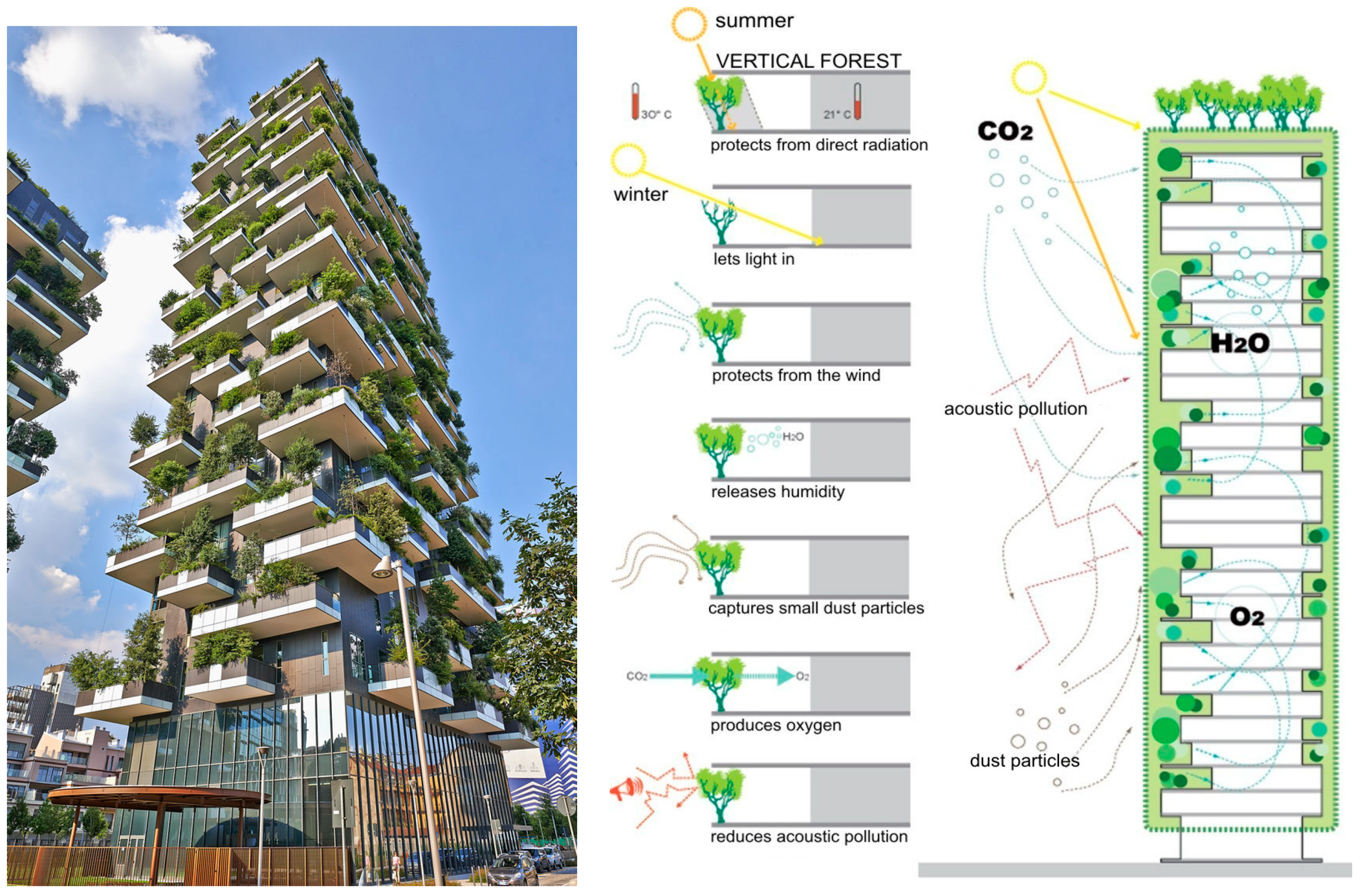
For the reasons mentioned in the introduction, considering that the energy performance of the cases examined was satisfied, the differences in operating energy consumption between the buildings identified were not considered, because they do not influence on the objectives of the study itself. In order to develop model 1, the construction framework of the vertical forest located in Milan, made by Stefano Boeri and completed in 2014, was selected. The texture of this building has been made with a load-bearing structure framed in reinforced concrete, a traditional shell and internal partitions [32,33,34] (Figure 2).
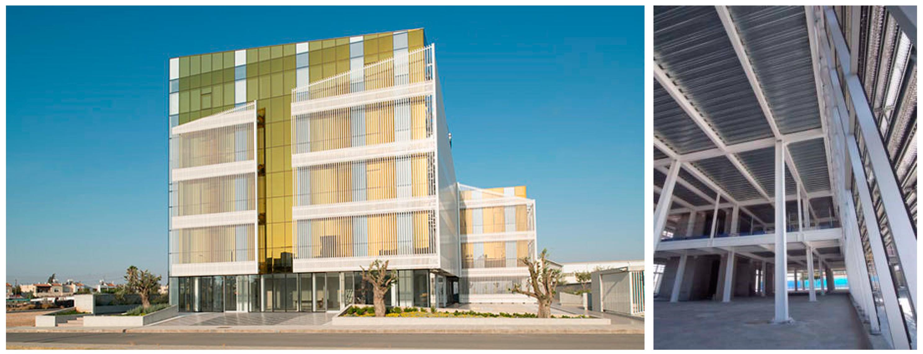
In order to develop model 2, the construction framework of the Karyatides Business Centre located in Cyprus, 2018, made by AI Architects, was selected. The texture of this building has been made with a skeleton in metal carpentry, horizons in trapezoidal sheet metal with collaborative casting and a stratified dry shell [35,36] (Figure 3).
In order to develop model 3, the construction framework of the multi-storey residential building in Murray Grove, London, 2009, made by Waugh Thistleton Architect, was selected. The texture of this building has been made with a X-Lam structural technology and fiber cement sheet envelope on a metal substructure [37,38,39,40,41] (Figure 4).

2.1.2. Characterization of the Structural Materials

In the second phase, the variable building systems are identified in order to recognize the sensitive indicators: The load-bearing structure; the slabs; the envelope; the internal partitions. Other systems (windows, installations, renewable sources, etc.) were not considered for the calculation because they were considered invariant. Therefore, on the basis of the executive design documents, the variable systems were analyzed in detail for the purposes of their technological and dimensional characterization. Technological characterization is an essential element of the methodology, as it is necessary to determine the exact weight of the individual materials which affects the overall calculation of EE and EC.

2.1.3. Estimation of the Amount of Embodied Energy and Embodied Carbon, Considering Virgin Materials

The third phase concerns the development of the calculations, with reference to the EE and EC coefficients associated with building materials in the inventory of carbon and energy (ICE), drawn by the University of Bath (England) in 2011 [1]. For the development of the first calculation phase, the coefficients of primary materials were considered which are composed predominantly of virgin material (as specified in the ice inventory of the University of Bath) [1]. The calculation was carried out analytically, multiplying the weight of the materials with the respective coefficients of EE and EC. The quantities of materials were determined on the basis of an urban renovation, demolition and reconstruction project of a residential neighborhood in the province of Salerno, Italy, for the reconstruction of the neighborhood, assuming the use of the three technological scenarios underlying the method.

2.1.4. Estimation of the Percentage Reduction Coefficient, of Embodied Energy and Embodied Carbon, Considering the Secondary Materials

For the development of the second calculation phase, the EE and EC coefficients were used again from the same ICE inventory for secondary materials. Secondary raw materials (MPS) are scraps from the production process that can be recovered through recycling activities and fed back into another production cycle as raw-second materials (materials derived from a process of recovery or reuse, recycling or recovery of waste, of which it is possible to identify the origin, type and characteristics of waste from which it can be produced, as well as the operations of reuse, recycling or recovery that produce them) [42]. These recycling operations and their re-introduction into new production cycles make it possible to overcome the, from cradle to grave, approach to materials and to aim for a more sustainable approach called from cradle to cradle.

2.1.5. Estimation of the Percentage Reduction Coefficient, of Embodied Energy and Embodied Carbon

In the fifth phase, the possibility of a further reduction of embodied energy is identified by intervening on non-structural systems (envelope and roofing) through the forecast of materials with lower embodied energy. The substitution criterion considered the possibility of providing materials with a lower coefficient of embodied energy, but with the same performance characteristics as those to be replaced. This approach constitutes an improvement scenario aimed at further lightening the building’s embodied impact and acting on the invisible parts of the building, i.e., without altering the aesthetic-formal characteristics that distinguish it as a work of contemporary architecture.

2.2. Calculation Tools and Model Development

Regarding the project for the reconstruction of the residential neighborhood in the province of Salerno, the quantities relating to the main elements of the structure (partitions, staircase and elevator blocks, external building envelope, plankings, as indicated in Table 1, Table 2 and Table 3) have been calculated from a parcel independent from the functional and plant engineering point of view. Three possible structural solutions (M-1, M-2, M-3) were hypothesized with three different structural materials (concrete, steel, wood). Regarding the entire technological characterization, reference was made to three works carried out (Figure 2, Figure 3 and Figure 4).
Two calculation systems were developed:
- The weights of the building components were multiplied by the EE and EC coefficients of the building materials relative to the primary materials.
- The weights of the building components were multiplied by the EE and EC coefficients of the building materials for the secondary materials.
The incidence of the respective values (EE, EC) was determined for a functional unit, i.e., per square meter of useful indoor area.

3. Results

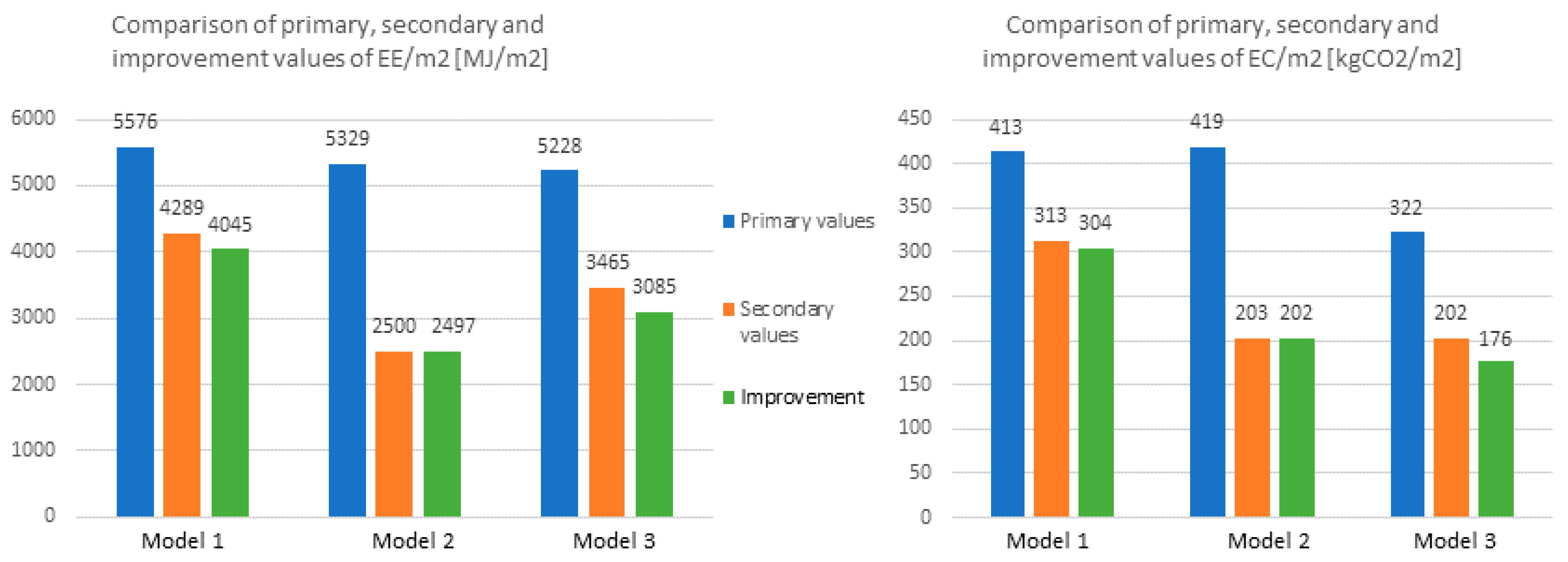
The following histograms (Figure 5) show that model 3, made of wood is the construction system with the lowest value of embodied energy and embodied primary carbon, and therefore better from the point of view of environmental impact. These values were EE3=5228 MJ/m2 and EC3=322 kg CO2/m2 respectively. For models 1 and 2 the values were higher, respectively EE1= 5576 MJ/m2 EC1= 413 kg CO2/m2, EE2= 5329 MJ/m2 EC2= 419 kg CO2/m2.

3.1. Results of the First Mitigation Strategy (Secondary Materials)

The first mitigation strategy, consisting of the use of secondary material indices, reduced the embodied energy and embodied carbon values. The structural materials of model 2, with steel supporting structure, achieved the greatest reduction in EE and EC values. This is due to is the composition of materials and components that are most suitable for recycling or re-introduction into the production cycle: Steel for the supporting structure; steel for the connections; aluminium profiles; plasterboard; stainless steel for supports and wood, glass. The EE and EC mitigation of this model was, respectively, approximately 53% and 51%, exceeding by 30 and 27 percentage points for model 1 (concrete), and by 20 and 14 percentages points for model 3 (timber).

3.2. Results of the Second Mitigation Strategy (Improvement)

The second mitigation strategy consisted of replacing insulating materials with lower coefficients of EE and EC than those used in the design of the structural materials. In particular, the insulating materials of the envelope, the roof and the slabs were replaced. The insulation materials used in the design of model 1, stone wool plaster, and EPS insulator, were replaced with cork panel. In model 2, the cork panel replaced the glass wool insulation material on the roof. In model 3, the cork panel replaced the insulation material used for the envelope, horizons roof, stone and wool plaster.
This strategy led to more reductions in embodied energy and embodied carbon (Table 4).
Overall, the adopted strategies have made it possible to achieve the following percentage reductions, starting with the content of EE and EC primary:

4. Discussions

The results confirmed the validity of the method already developed by the authors, on an experimental basis, for comparing the overall energy consumption of simulated wet and dry construction systems [43]. The traditional building systems in load-bearing masonry and concrete (model 1), classified as wet systems, are mainly massive systems, and require the use of a greater quantity of materials than the dry building systems, which are mainly light, such as steel and wood (models 2–3).
The mitigation strategies adopted made it possible to obtain a reduction in embodied energy and embodied carbon for all three structural materials analyzed. In particular (Table 5) the greatest percentage reduction was obtained for model 2 (steel).
Dry technological systems help to further reduce the production of EE and EC, with a view to a possible second life cycle of the building component. In fact, the inventory of carbon and energy [1], used for this study, foresees a significant reduction in the EE and EC coefficients between the primary (virgin) material and the secondary, i.e., recycled material. The concrete of a building at the end of its useful life, after separation of the reinforcement of the steel, can be recycled, but for non-structural uses (it can, for example, be reused as inert, just like sand and crushed stone). Steel or X-LAM wood components can be reused or recycled for further use with the same original functions and performance. The construction of buildings with secondary materials leads to a reduction of energy consumed for new processes and a greater gain in terms of environmental impacts, compared to buildings built with virgin raw materials.
These considerations should push designers, and all actors involved in the management and construction of a building, towards the use of dry technological systems.
Moreover, the dry technological system with stratified partitions proves to be more resilient than the wet, as it allows the interchangeability of the component layers. This is possible both in the design phase (preferring materials with a lower energy and carbon coefficient incorporated) and in the operational phase of the building, with respect to the evolution of current legislation.
The architectural works selected for the development of the method show that it is possible to pursue the objective of reducing the embodied energy and embodied carbon, without diminishing the level of aesthetic quality of the architecture (Table 6).

5. Conclusions

The study aimed at identifying the construction system with the lowest embodied energy and carbon (according to the dual hypothesis of using primary or secondary materials). With reference to the method of selection of case studies, the development of the model took into account a passive approach, i.e., considering all the structural elements of the respective construction systems under investigation (the plant systems, considered invariant, were not included in the calculation model). The attention to the physical components of the building shifts in second order the characters of the subjective nature, such as the morphology and the intended use. The case studies have been identified as representative of a particular technological system (and of recognized value in the contemporary architectural landscape), as well as having been carried out after the first Energy Performance Building Directive (2002/91/EC-EPBD). The method hypothesized the use of each of the three selected building systems for the reconstruction of a residential building neighborhood through parametric values. Therefore, the reference to the case studies is only technological, and does not depend on the location, type, morphology, or use of the building.
The study developed aims to provide useful information to operators in the construction sector in order to adopt design choices with the lowest possible environmental impact.
The critical analysis of the results obtained has made it possible to identify in the dry construction system (with reference to the 2–3 models, with a metal or wooden supporting structure), the most functional design solution to the requirements underlying the method.
The choice of the dry construction system is also validated by the economic convenience analyses carried out by specific studies in the sector. From these analyses, the need to compensate for a clear production gap between the construction industry and the serial production industries has emerged, and the adoption of the off-site construction process for this sector [44] is preferred.
The modular construction sector has made considerable progress in implementing construction processes and in providing numerous types of sophisticated and complex structures. Modularization is known for its timesaving advantages and is recognized to be a more resource-efficient process and inherently greener.
The challenge that is launched, and in some way, this study that is able to provide an initial response, is the ability to comply with regulatory requirements (increasingly mandatory) without diminishing the aesthetic-formal qualities of the architectural work.

Author Contributions

E.S., G.D.R. and R.M. designed and structured the article. E.S. has deepened the national and international regulatory framework related to embodied energy and carbon emissions produced by the construction industry. He has also deepened the framework of the contribution within the international scientific community. G.D.R. has defined the objectives, has deepened the methodological approach, through the identification of significant indicators, and has conceived the strategic project hypotheses. R.M. has contributed to the development of the method, based on the objectives set and on the application of the method to the case studies. She has also contributed to the drafting of tables and graphs summarizing the results obtained.

Funding

This research received no external funding.

Conflicts of Interest

The authors declare no conflict of interest.

References

  1. Hammond, G.; Jones, C.I. Embodied Carbon: The Concealed Impact of Residential Construction. Green Energy Technol. 2009, 31, 367–384. [Google Scholar]
  2. Communication from the Commission to the European Parliament, the Council, the European Economic and Social Committee and the Committee of the Regions—Energy Technologies and Innovation. 2013. Available online: https://ec.europa.eu/energy/sites/ener/files/swf_2013_0158_en.pdf (accessed on 13 May 2019).
  3. Crowther, P. Design for disassembly to recover embodied energy. In Proceedings of the 16th Annual Conference on Passive and Low Energy Architecture, Melbourne, Brisbane, Cairns, 22–24 September 1999. [Google Scholar]
  4. Ding, G. The Development of a Multi-Criteria Approach for the Measurement of Sustainable Performance for Built Projects and Facilities. Ph.D. Thesis, University of Technology, Sydney, Australia, 2004. [Google Scholar]
  5. Sartori, I.; Hestnes, A.G. Energy use in the life cycle of conventional and low energy buildings: A review article. Energy Build. 2007, 39, 249–257. [Google Scholar] [CrossRef]
  6. Keoleian, G.A.; Blanchard, S.; Reppe, P. Life-cycle energy, costs, and strategies for improving a single family house. J. Ind. Ecol. 2000, 4, 135–156. [Google Scholar] [CrossRef]
  7. Hannon, B.; Stein, R.G.; Segal, B.Z.; Serber, D. Energy and labor in the construction sector. Science 1978, 202, 837–847. [Google Scholar] [CrossRef] [PubMed]
  8. Nassen, J.; Holmberg, J.; Wadeskog, A.; Nyman, M. Direct and indirect energy use and carbon emissions in the production phase of buildings: An input output analysis. Energy 2007, 32, 1593–1602. [Google Scholar] [CrossRef]
  9. Crawford, R.H.; Treloar, G.J. Validation of the use of Australian input output data for building embodied energy simulation. In Proceedings of the 8th International IBPSA Conference, Eindhoven, The Netherlands, 11–14 August 2003. [Google Scholar]
  10. Pacheco-Torgal, F.; Faria, J.; Jalali, S. Embodied energy versus operational energy. Showing the shortcomings of the energy performance building directive (EPBD). Mater. Sci. Forum 2013, 730, 587–591. [Google Scholar] [CrossRef]
  11. Thormark, C. The effect of material choice on the total energy need and recycling potential of a building. J. Build. Environ. 2006, 41, 1019–1026. [Google Scholar] [CrossRef]
  12. Castro, R.; Terranova, E.; Bruce-Hyrkäs, T.; Pasanen, P. The Embodied Carbon Review—Embodied Carbon Reduction in 100+ Regulations & Rating Systems Globally. Available online: https://www.oneclicklca.com/wp-content/uploads/2018/12/Embodied_Carbon_Review_2018.pdf (accessed on 21 May 2019).
  13. Brighton and Hove City Council. Brighton and Hove City Council Climate Change Strategy. 2011. Available online: https://present.brighton-hove.gov.uk/Published/C00000120/M00003226/AI00022734/$20111031151124_001100_0002279_MicrosoftWordBrightonHoveCityClimateChangeStrategyNOVEMBER2011.pdfA.ps.pdf (accessed on 9 July 2019).
  14. AIA. AIA Guide to Building Life Cycle Assessment in Practice; AIA: Washington, DC, USA, 2010. [Google Scholar]
  15. RICS. Methodology to Calculate Embodied Carbon of Materials; Royal Institution of Chartered Surveyors: London, UK, 2012. [Google Scholar]
  16. KBOB; eco-bau; IPB. KBOB-Empfehlung 2009/1:2014: Ökobilanzdaten im Baubereich, from April 2014. Koordinationskonferenz der Bau- und Liegenschaftsorgane der öffentlichen Bauherren c/o BBL Bundesamt für Bauten und Logistik. KBOB: Bern, Germany, 2014. Available online: https://www.kbob.admin.ch/dam/kbob/de/dokumente/Publikationen/Nachhaltiges%20Bauen/Archiv_2010-2014/2009_1_2014_Empfehlung_Oekobilanzdaten_Baubereich.pdf.download.pdf/2009_1_2014_Empfehlung_Oekobilanzdaten_Baubereich.pdf (accessed on 16 May 2019).
  17. Brown, M.T.; Herendeen, R.A. Embodied energy analysis and EMERGY analysis: A comparative view. Ecol. Econ. 1996, 19, 219–235. [Google Scholar] [CrossRef]
  18. Lenzen, M. Primary energy and greenhouse gases embodied in Australian Final consumption: An input-output analysis. Energy Policy 1998, 26, 495–506. [Google Scholar] [CrossRef]
  19. International Energy Agency. Evaluation of Embodied Energy and CO2eq for Building Construction (Annex 57). 2016. Available online: http://www.annex57.org/wp/wp-content/uploads/2017/05/Overview-Report.pdf (accessed on 16 May 2019).
  20. Ferng, J. Toward a scenario analysis framework for energy footprints. Ecol. Econ. 2002, 40, 56–69. [Google Scholar] [CrossRef]
  21. Weidema, B.P.; Thrane, M.; Christensen, P.; Schmidt, J.H.; Løkke, S. Carbon footprint. J. Ind. Ecol. 2008, 12, 3–6. [Google Scholar] [CrossRef]
  22. Chang, Y.; Ries, R.J.; Wang, Y. The embodied energy and environmental emissions of construction projects in China: An economic input–output LCA model. Energy Policy 2010, 38, 6597–6603. [Google Scholar] [CrossRef]
  23. Druckman, A. The carbon footprint of UK households 1990–2004: A socio-economically disaggregated, quasi-multi- regional input–output model. Ecol. Econ. 2009, 68, 2066–2077. [Google Scholar] [CrossRef]
  24. Ozawa-Meida, L. Measuring carbon performance in a UK University through a consumption-based carbon footprint: De Montfort University case study. J. Clean. Prod. 2013, 56, 185–198. [Google Scholar] [CrossRef]
  25. Tukker, A.; Bulavskaya, T.; Giljum, S.; de Koning, A.; Lutter, S.; Simas, M.S.; Stadler, K.; Wood, R.W.W. The Global Resource Footprint of Nations; Carbon, Water, Land and Materials Embodied in Trade and Final Consumption Calculated with EXIOBASE 2.1. 2014. Available online: http://www.truthstudio.com/content/CREEA_Global_Resource_Footprint_of_Nations.pdf (accessed on 9 July 2019).
  26. DIRETTIVA 2014/24/UE DEL PARLAMENTO EUROPEO E DEL CONSIGLIO del 26 febbraio 2014 sugli appalti pubblici e che abroga la direttiva 2004/18/CE. 2014. Available online: https://eur-lex.europa.eu/legal-content/IT/TXT/PDF/?uri=CELEX:02014L0024-20160101&rid=1 (accessed on 15 May 2019).
  27. Crepaldi, G. Gli acquisti eco-sostenibili nel nuovo Codice dei Contratti Pubblici Italiano: considerazioni sul life cycle costing. Rev. Direito 2018. [Google Scholar] [CrossRef]
  28. Moncaster, A.; Symons, K.E. A method and tool for ‘cradle to grave’ embodied carbon and energy impacts of UK buildings in compliance with the new TC350 standards. Energy Build. 2013, 66, 514–523. [Google Scholar] [CrossRef]
  29. Sarkisian, M.; Shook, D. Quantifying Embodied Carbon in Concrete Construction: Case Studies, February 2013. Available online: https://www.researchgate.net/publication/328782567_Quantifying_Embodied_Carbon_in_Concrete_Construction_Case_Studies (accessed on 18 May 2019).
  30. Moncaster, A.; Gavotsis, E. Improved Embodied Energy and Carbon Accounting: Recommendations for Industry and Policy. In Architecture Anthology II: Architectural Technology; Alifragkis, S., Patricios, N., Eds.; Athens Institute for Education & Research (ATINER): Athina, Greece, 2016. [Google Scholar]
  31. Pomponi, F.; Moncaster, A. Benefits and Challenges of Visualising Embodied and Whole Life Carbon of Buildings. In Proceedings of the International SEEDS Conference 2016: Sustainable Ecological Engineering Design for Society, Leeds, UK, 14–15 September 2016. [Google Scholar]
  32. Goud, R.; Chauhan, N.K.; Lokhande, H.; Bohre, S.; Kochar, Y.; Soni, M.; Pathak, A. Vertical Forest in multistory Residential Cum Commercial to Eliminate Pollution by Hydroponic Method. Int. J. Eng. Res. Adv. Technol. 2018, 4, 72–78. [Google Scholar] [CrossRef]
  33. Vodenova, P.; Angelova, D. Residential Design Regeneration. A New Approach to Dwelling Process. 2014. Available online: https://www.researchgate.net/publication/273831663 (accessed on 23 April 2019).
  34. Potienko, N.D.; Kuznetsova, A.A.; Solyakova, D.N.; Klyueva, Y.E. The Global Experience of Deployment of Energy-Efficient Technologies in High-Rise Construction. E3S Web Conf. 2018, 33, 01017. [Google Scholar] [CrossRef] [Green Version]
  35. Karyatides Business Centre a Nicosia (Cipro)—Ai Architects. Available online: https://www.arketipomagazine.it/karyatides-business-centre-a-nicosia-cipro-ai-architects/ (accessed on 23 April 2019).
  36. ARCHITETTURA IN ACCIAIO 24. 2018. Available online: https://www.promozioneacciaio.it/cms/it7374-architetture-in-acciaio-23.asp (accessed on 24 April 2019).
  37. Altamura, P. Costruire a Zero Rifiuti, Ricerche di Tecnologia dell’architettura; FrancoAngeli: Milano, Italy, 2016. [Google Scholar]
  38. Legno in the City. Available online: http://www.promolegno.com/materialegno/02/legno-in-the-city/ (accessed on 26 April 2019).
  39. Murray Grove, The Original Timber Tower. Available online: http://waughthistleton.com/murray-grove/ (accessed on 26 April 2019).
  40. Lepage, R. Moisture Response of Wall Assemblies of Cross-Laminated Timber Construction in Cold Canadian Climates. Master’s Thesis, University of Waterloo, Ontario, Canada, 2012. [Google Scholar]
  41. Stadthaus, 24 Murray Grove, London. Available online: https://eoinc.weebly.com/uploads/3/0/5/1/3051016/murray_grove_case_study.pdf (accessed on 27 April 2019).
  42. Kavanagh, P. A Comparative Life Cycle Assessment for Utilising Laminated Veneer Bamboo as a Primary Structural Material in High-Rise Residential Buildings. Master’s Thesis, Technological University, Dublin, Ireland, 2018. [Google Scholar]
  43. Di Ruocco, G.; Melella, R. Evaluation of environmental sustainability threshold of “humid” and “dry” building systems, for reduction of embodied carbon (CO2). Int. J. Archit. Technol. and Sustain. 2018, 3. [Google Scholar] [CrossRef]
  44. Nesticò, A.; Moffa, R. Economic Analysis and Operational Research Tools for Estimating Productivity Levels in Offsite Construction; DEI srl: Rome, Italy, 2018. [Google Scholar]
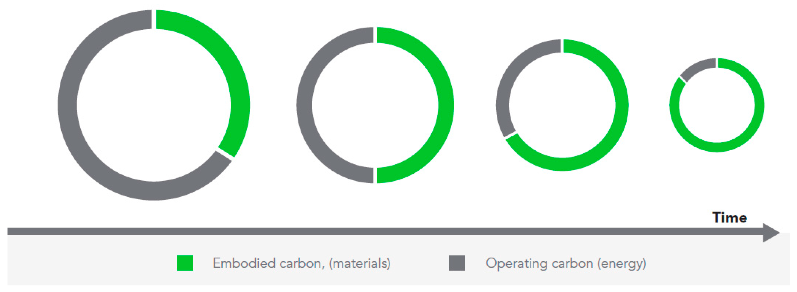
Figure 1. The trend of the ratio, over time, inversely proportional, between operating energy and embodied energy.
Sustainability 11 03806 g001
Figure 2. Stefano Boeri Architetti: Vertical Forest, Milan, 2014.
Sustainability 11 03806 g002
Figure 3. Ai Architects: Karyatides Business Centre, Nicosia (Cyprus), 2018.
Sustainability 11 03806 g003
Figure 4. Waugh Thistleton Architects: Murray Grove, London, 2009.
Sustainability 11 03806 g004
Figure 5. Histograms show the results of the application of the method to the three technological models.
Sustainability 11 03806 g005
Table 1. The calculation of the overall embodied energy (EE) and embodied carbon (EC) for the reinforced concrete construction system (M-1).
MODEL 1
(concrete)
Weight of Material (kg)Coefficient of EE
(MJ/kg)
Primary
Secondary
Coefficient of EC
(kgCO2/kg)
Primary
Secondary
Total EE
(MJ)
Primary
Secondary
Total EC
(kg CO2)
Primary
Secondary
SUPPORTING STRUCTURE
concrete pillars463,0501.110.159513,985.5073,624.95
rebars for pillars22,226.424.61.71546,769.4438,007.14
0.42195,592.329335.09
concrete on-board beams410,051.251.110.159455,156.8965,198.15
concrete flat beams60,1501.110.159672,826.5096,377.85
rebars for beams56,907.2724.61.711,399,918.8497,311.43
8.80.42500,783.9823,901.05
PARTITIONS
interior plaster (floor plan)89,2081.80.12160,574.4010,704.96
hollow brick178,4168.40.621,498,694.40110,617.92
interior plaster (ground floor)16,4161.80.1229,548.801969.92
hollow brick82,0808.40.62689,47250,889.60
STAIRWELL
interior plaster33,2641.80.1259,875.203991.68
hollow brick166,3208.40.621,397,088103,118.40
concrete for landings23,0400.950.1321,8882995.20
concrete for steps47,308.800.950.1344,943.366150.14
elevator structure198,0001.110.15921,978031,482
knee beam95,0401.110.159105,494.4015,111.36
incidence of reinf. Elevator structure 9504 24.6 1.71 233,798.40 16,251.84
8.80.4283,635.203991.68
incidence of reinf. beam5322.24 24.6 1.71 130,927.10 9101.03
8.80.4246,835.712235.34
incidence of reinf. Landings1843.2 24.6 1.71 45,342.72 3151.87
8.80.4216,220.16774.14
EXTERNAL BUILDING ENVELOPE
porcelain stoneware slabs77,164.7290.59694,482.5245,527.19
steel brackets (*)46,730.19 56.7 6.15 264,9601.77 287,390.67
111.54514,032.0971,964.49
stone wool plaster8387.4716.81.05140,909.508806.84
hollow brick438,279.758.40.623,681,549.90271,733.44
interior plaster53,919.451.80.1297,055.016470.33
PLANKINGS
screed425,9840.770.096328,007.6840,894.46
concrete slabs236,5921.110.159262,617.1237,618.13
concrete beams236,5921.110.159262,617.1237,618.13
incidence of reinf.22,712.83 24.6 1.71 558,735.67 38,838.94
8.80.42199,872.929539.39
hollow brick11,356.428.40.6295,393.897040.98
interior plaster45,425.661.80.1281,766.195451.08
FLAT ROOF
bituminous coating51,815.42470.482,435,324.9324,871.40
screed7161.830.770.0965,514.61687.53
EPS insulator10,422.9588.62.5923,473.4026,057.38
PVC film (*)18,336.67 77.2 2.41 1,415,591.08 44,191.38
15.10.6276,883.7511,002.00
concrete slab9650.881.110.15910,712.481534.49
concrete beams4045.921.110.1594490.97643.30
incidence of reinf.6161.66 24.6 1.71 151,576.93 10,536.44
8.80.4254,222.642587.90
hollow brick77,020.808.40.62646,974.7247,752.90
interior plaster21,457.201.80.1238622.962574.86
Table 2. The calculation of the overall embodied energy (EE) and embodied carbon (EC) for the steel construction system (M-2).
MODEL 2(steel)Weight of Material (kg)Coefficient of EE
(MJ/kg)
Primary
Secondary
Coefficient of EC
(kgCO2/kg)
Primary
Secondary
Total EE
(MJ)
Primary
Secondary
Total EC
(kg CO2)
Primary
Secondary
SUPPORTING STRUCTURE
steel pillars72,766.51 24.4 1.77 1,775,502.89 128,796.73
9.50.43691,281.8631,289.60
on-board beams42,005.65 24.4 1.77 1,024,937.86 74,350
9.50.43399,053.6718062.43
internal beams539,19.87 24.4 1.77 1,315,644.86 95,438.17
9.50.43512,238.7823,185.54
connections15,182.28 24.4 1.77 370,447.70 26,872.64
9.50.43144,231.696528.38
PARTITIONS
plasterboard (*)92,776.32 6.75 0.38 626,240.16 35,255
2.240.095207,818.968814
aluminium profiles26,359.83 154 8.16 4,059,413.82 215,096.21
34.11.98898,870.2052,192.46
STAIRWELL
interior plaster33,2641.80.1259,875.23991.68
concrete stairwell554,4001.110.159615,38488,149.6
plaster floor plan95041.110.15910,549.441511.14
concrete stairwell floor plan158,4001.110.159175,82425,185.6
concrete landings23,0400.950.1321,8882995.2
concrete steps47,308.800.950.1344,943.366150.14
concrete stairwell19,80001.110.159219,78031,482
incidence of reinf43,718.4024.61.711,075,472.6474,758.46
incidence of rein. Landings1843.2024.61.7145,342.723151.87
EXTERNAL BUILDING ENVELOPE
wooden box sunshades (*)31632.52 8.5 0.46 268,876.462 14,550.961
0.330.1210,438.733795.90
metal supporting elements (*)67080 56.7 6.15 3,803,436 412,542
111.54737,880103,303
insulating glass (*)106285.28 15 0.85 1,594,279.26 90,342.491
6.630.21704,671.4322,319.91
PLANKINGS
collaborative concrete casting865,2801.110.159960,461137,579
corrugated sheet57,491.8631.52.511,810,993.46144,304.56
aluminium profiles4083.26 154 8.16 628,822.66 33,319.43
34.11.98139,239.308084.86
plasterboard (*)62,300.16 6.75 0.38 420,526 23,674
2.240.095139,5525918
FLAT ROOF
bituminous coating6433.92470.48302,394.243088.28
glasswool insulation (*)1286.78 28 1.35 36,029.95 1737.16
11.90.3415,312.73437.51
collaborative concrete casting52,149.501.110.15957,885.948291.77
corrugated sheet3465.9431.52.51109,176.988699.50
aluminium profiles (*)1020.82 154 8.16 157,205.66 8329.86
34.12.0434,809.822082.46
plasterboard (*)16,736.62 6.75 0.38 112,972.16 6359.91
2.240.09537,490.011589.98
Table 3. The calculation of the overall embodied energy (EE) and embodied carbon (EC) for the timber construction system (M-3).
MODEL 3(timber)Weight of Material (kg)Coefficient of EE
(MJ/kg)
Primary
Secondary
Coefficient of EC
(kgCO2/kg)
Primary
Secondary
Total EE
(MJ)
Primary
Secondary
Total EC
(kg CO2)
Primary
Secondary
PARTITIONS
plasterboard (*)92,776.32 6.75 0.38 626,240.16 35,255
2.240.095207,818.968814
aluminium profiles26,359.83 154 8.16 4,059,413.82 215,096.21
34.11.98898,870.2052,192.46
XLAM panel101,498.88120.651,217,986.5665,974.27
STAIRWELL
landings3686.40120.6544,236.82396.16
steps7569.40120.6590,832.94920.11
elevator structure31,680120.65380,16020,592
partitions88,704120.65106,444857,657.60
internal plaster33,2641.80.1259,875.23991.68
EXTERNAL BUILDING ENVELOPE
Fibrecement slabs57514.0810.92.11626,903.47121,354.71
steel brackets (*) 46,730.19 56.7 6.15 2,649,601.77 287,390.67
111.54514,032.0971,964.49
insulation117,424.5816.81.051,972,732.94123,295.81
XLAM panel122,696.70120.651,472,360.4579,752.86
aluminium profiles3522.96 154 8.16 542,535.84 28,747.35
34.11.98120,132.946975.46
plasterboard (*)64,703.34 6.75 0.38 436,747.54 24,587.27
2.240.095144,935.486146.82
PLANKINGS
subfloor18,3040.770.09614,094.081757.18
Rubber mat 7072101.73.1871,922222,488.96
XLAM slab 9717.76120.65116,613.126316.54
stone wool plaster582.416.81.059784.32611.52
aluminium profiles4083.26 155 8.24 632,905.92 33,646.09
34.11.98139,239.308084.86
plasterboard (*)3893.76 6.75 0.38 26,282.88 1479.63
2.240.0958722.02369.91
FLAT ROOF
concrete floor101,736.361.240.127126,153.0912,920.52
Rubber mat34,180.20101.73.183,476,126.34108,693.04
XLAM slab46,967.62120.65563,611.3930,528.95
stone wool plaster2814.8416.81.0547,289.312955.58
aluminium profiles1020.82 155 8.24 157,205.66 8329.86
34.11.9834809.832021.22
plasterboard (*)18,819.22 6.75 0.38 127,029.71 7151.30
2.240.09542,155.041787.82
(*) The coefficients of secondary EC, relative to the materials indicated with the asterisk, not being present in the ICE Inventory, have been obtained by normalization with respect to the corresponding primary EC coefficient.
Table 4. Percentages of reduction of EE and EC, between primary, secondary and improvement materials.
EE
Primary
Secondary
Improvement
EC
Primary
Secondary
Improvement
Mitigation
EE
Mitigation
EC
M-15576
4289
4045
413
313
304
23.08%
5.69%
24.21%
2.87%
M-25329
2500
2497
419
203
202
53.08%
0.12%
51.55%
0.49%
M-35228
3465
3085
322
202
176
33.72%
10.97%
37.27%
12.87%
Table 5. The determination of the total weight and the weight per functional unit of the respective construction systems.
Construction SystemTotal Weight (kg)Incidence (kg/m2)
concrete (M-1)1479251363.18
steel (M-2) 168692 41.42
timber (M-3)28088168.96
Table 6. The overall percentage reduction of EE and EC values.
ModelEE ReductionEC Reduction
1−28.77%−27.08%
2 −53.20% −52.04%
3−44.69%−50.14%