Article

Power Flow Control Strategy and Reliable DC-Link Voltage Restoration for DC Microgrid under Grid Fault Conditions

by
Thanh Van Nguyen
and
Kyeong-Hwa Kim
*
Department of Electrical and Information Engineering, Seoul National University of Science and Technology, 232 Gongneung-ro, Nowon-gu, Seoul 01811, Korea
*
Author to whom correspondence should be addressed.
Sustainability 2019, 11(14), 3781; https://doi.org/10.3390/su11143781
Submission received: 1 June 2019 / Revised: 5 July 2019 / Accepted: 6 July 2019 / Published: 10 July 2019
(This article belongs to the Special Issue Integration of AC/DC Microgrids into Power Grids)

Abstract

:
In this paper, an effective power flow control strategy (PFCS) based on the centralized control method and a reliable DC-link voltage (DCV) restoration algorithm for a DC microgrid (DCMG) under grid fault conditions are proposed. Considering the relationship of supply-demand power and the statuses of system units, thirteen operating modes are presented to ensure the power balance in DCMG under various conditions. In the PFCS, the battery charging/discharging procedure is implemented considering the battery power limit to avoid overheating and damage. Moreover, load shedding and load reconnection algorithms are presented to maintain the system power balance, even in critical cases. To prevent the system power imbalance in DCMG caused by the delay of grid fault detection, a reliable DCV restoration algorithm is also proposed in this paper. In the proposed scheme, as soon as abnormal behavior of the DCV is detected, the battery or wind power generation system instantly enters a local emergency control mode to restore the DCV rapidly to the nominal value, regardless of the control mode assigned from the central controller. Comprehensive simulations and experiments based on the DCMG testbed are carried out to prove the effectiveness of the PFCS and the proposed DCV restoration algorithm.

1. Introduction

In recent years, renewable energy sources (RESs) such as wind and solar are attracting a great deal of attention due to the scarcity of fossil energy and environmental issues [1]. For the purpose of integrating various RESs into the utility grid (UG), distributed generations (DGs), which are the main parts of microgrids (MGs), have been considered and developed [2]. Due to the advantages of easy resource integration, flexible installation location, and reliable operation, DG-based MGs have become a future trend in constructing electric power systems [3]. Energy storage systems (ESSs) are usually integrated with MG in order to improve the reliability of system operation by reducing the effect of the intermittent nature of RESs [4].
According to the types of bus voltage, MGs can be classified into DC microgrids (DCMGs), AC microgrids (ACMGs), and hybrid AC/DC microgrids [5]. In comparison with other configurations, the control of DCMG is simpler, since the system power balance can be guaranteed only by regulating the DC-link voltage (DCV) to its nominal value without consideration of reactive power, current harmonics, frequency stability, and phase imbalance [6,7].
Regarding the communication perspective, the DCMG control method can be mainly divided into three categories: decentralized control [8,9,10], distributed control [11,12], and centralized control [6,13,14]. In decentralized control, DC-bus signaling (DBS) is well known as a simple and effective autonomous power control method [9]. In the DBS approach, the DCV is used as an indicator to determine the operating mode of system units according to predefined voltage thresholds. Even though the DBS method has the advantage of simplicity of control, its performance depends significantly on the selection of appropriate voltage thresholds. If the difference between two voltage thresholds is too large, the DCV begins to fluctuate. In contrast, if the selected difference is too small, the determination of operating modes is strongly affected by sensor inaccuracies, which may lead to unnecessary and frequent mode switching [15]. In Ref [10], a communication-free method is proposed to manage the power in the system. In this study, the power management strategy is based on the fixed setpoints of the DCV and the active power outputs. Generally, the decentralized control has the performance limitations of the entire system control, since each system unit lacks information about the others. In order to overcome this weakness, the distributed control, which constructs a simple communication network to share the information among neighboring system units, has been considered and developed [11]. Because only neighboring units are connected, a consensus algorithm is required in this method to obtain global information. In spite of the advantages of distributed control, it still has the limitations, such as the effect of measurement errors and the complexity of analytical performance analyses for the convergence speed of the consensus algorithm [12,15]. Unlike the above two methods, in the centralized control approach, a central controller (CC) is formed to collect the necessary data from local controllers (LCs), which then sends optimal decisions back to LCs to control power exchanges and to guarantee the system’s stability under various conditions [5]. By implementing CC, other concerns in DCMG, such as the cost minimization [13] and adaptive protection [14], can also be realized easily.
Recently, many power flow control strategies (PFCSs) based on the centralized control approach have been presented for the purpose of ensuring the system power balance under various conditions [16,17,18,19]. In Ref [16], an improved voltage control strategy for a DCMG composed of photovoltaic and hybrid ESSs, such as batteries and supercapacitors, is proposed to stabilize the DCV. In this scheme, the entire system operation is divided into four states with individual control modes considering the photovoltaic generation power, load demand, and battery state of charge ( S O C ). In Ref [17], a PFCS based on the peak load demand durations in UG, and the optimal usage of RES is studied. However, in this work, the maximum charging and discharging power limit of the battery are not taken into account, which may affect the power control strategy in some cases. For instance, in case of power shortage, it is probable that the DCMG would request the discharging power from battery, exceeding the maximum capability. Similarly, the required charging power to the battery may be greater than the maximum absorbed capability in power surplus situations. In both cases, maintaining the power balance in DCMG by a battery is not possible due to the power limit. To deal with this issue, the maximum charging and discharging currents of the battery are considered in the design of PFCS under the grid-connected mode in Ref [18]. In Ref [19,20], to avoid the system collapse in case of power shortage, an appropriate load shedding (LS) is implemented to disconnect less important loads. On the other hand, to prevent the DC-link from overvoltage in case of power surplus, another approach halts the RESs conversion system [9] or uses the voltage control mode (VCM) [16,21]. In practice, it is necessary to reconnect some disconnected loads as the entire system becomes stable after the LS action [22]. Even though a load reconnection (LR) is considered in Ref [23,24], a reliable sequence of reconnection is neither completely analyzed nor presented in these studies.
In the centralized control approach, the UG is a main source to guarantee the system power balance in the grid-connected mode. When a fault in the UG is detected by a fault detection device, the fault signal is sent to the CC by a communication line. Then, the CC changes the system operation into the islanded mode and assigns other units such as battery or wind power generation systems (WPGS) to maintain the system power balance. In practice, however, the CC cannot instantly change the system operation into the islanded mode due to the delay caused by fault clearance time, data transmission time, and the processing time of CC. Consequently, any source or power converter does not take on the role of temporarily regulating the DCV, resulting in a power system imbalance. To address this problem, much research focusing on grid fault detection schemes has been carried out for the purpose of reducing the time delay [25,26]. However, detecting the grid fault accurately and rapidly is still a challenging issue [27].
This paper presents an effective PFCS and a reliable DCV restoration algorithm for DCMG under grid fault conditions. The effective PFCS is achieved based on the centralized control method for DCMG, which consists of a UG connection system, a WPGS, a battery-based ESS, and DC loads. The power flow in DCMG can be autonomously and reliably controlled under both the grid-connected and islanded conditions by using the relationship of supply-demand power and battery status. By implementing the constant current-constant voltage (CC-CV) method for the battery charging operation with the consideration of the battery power limit, the overheating or damage caused by undesirable overcharging/overdischarging is avoided, which expands the battery life significantly. This paper also develops an effective LS algorithm considering the S O C and the maximum capability of the battery to maintain the system power balance, even in the critical cases. Beside LS, an LR algorithm is also implemented for the purpose of reconnecting the loads which are initially disconnected due to power shortage in DCMG. In both the LS and LR algorithms, a time delay is applied to avoid undesirable load disconnections or reconnections caused by noise. In order to deal with the system power imbalance caused by the delay of grid fault detection, the DCV restoration algorithm is proposed in this paper. In the proposed DCV restoration algorithm, a local emergency control mode (LECM) is introduced to restore the DCV quickly to a nominal value. The LECM, which is achieved by LCs either with the battery-based ESS or the WPGS, operates regardless of the control signals from the CC under critical conditions for the purpose of ensuring the system power balance. To validate the effectiveness of the PFCS including LS and LR, as well as the proposed DCV restoration algorithm, both simulations based on the PSIM software and experiments based on prototype laboratory DCMG testbed are carried out.
This paper is organized as follows: Section 2 describes the configuration of DCMG. The details of the PFCS and system control methods of DCMG are discussed in Section 3. Section 4 presents the proposed DCV restoration algorithm. The simulation and experimental results are shown in Section 5 and Section 6, respectively. Section 7 presents the discussion. Finally, Section 8 concludes the paper.

2. System Configuration of DCMG

Figure 1 shows the configuration of a DCMG which consists of four main units, namely, WPGS, battery-based ESS, UG connection system, and DC loads, where P G is output power of UG connection system, P B is battery power, P W is output power of WPGS, and P L is load power. In the WPGS, a permanent magnet synchronous generator (PMSG) is employed to convert the wind turbine mechanical output power into electrical power. The PMSG is widely used in WPGS because it has a simple structure, high efficiency, and a wide operating range. The output power of the PMSG is injected into the DC-link through a unidirectional AC/DC converter. Due to the fluctuation of wind power, battery-based ESS is normally coordinated with WPGS in DCMG to stabilize the DCV and system power flow. To interface the battery-based ESS, an interleaved bidirectional DC/DC converter, which exchanges the power between the battery and DC-link, is employed. By using the interleaved bidirectional converter, the output current ripples are notably reduced. As a result, this improves the charging performance and extends the battery life [28]. For the purpose of interacting DCMG with UG in the grid-connected mode, a UG connection system, including a transformer and a bidirectional AC/DC converter, is constructed. The UG connection system not only maintains a supply-demand power balance of the DCMG, but also injects high quality current into UG depending on the DCMG operation modes. In the system configuration, a CC determines all the operating modes of the DCMG units. A power converter equipped with LC is implemented to operate each DCMG unit according to the control mode assigned from the CC. Load management is also achieved by the CC to accomplish the LS and LR algorithms.

3. Power Flow Control Strategy and System Control of DCMG

3.1. Power Flow Control Strategy

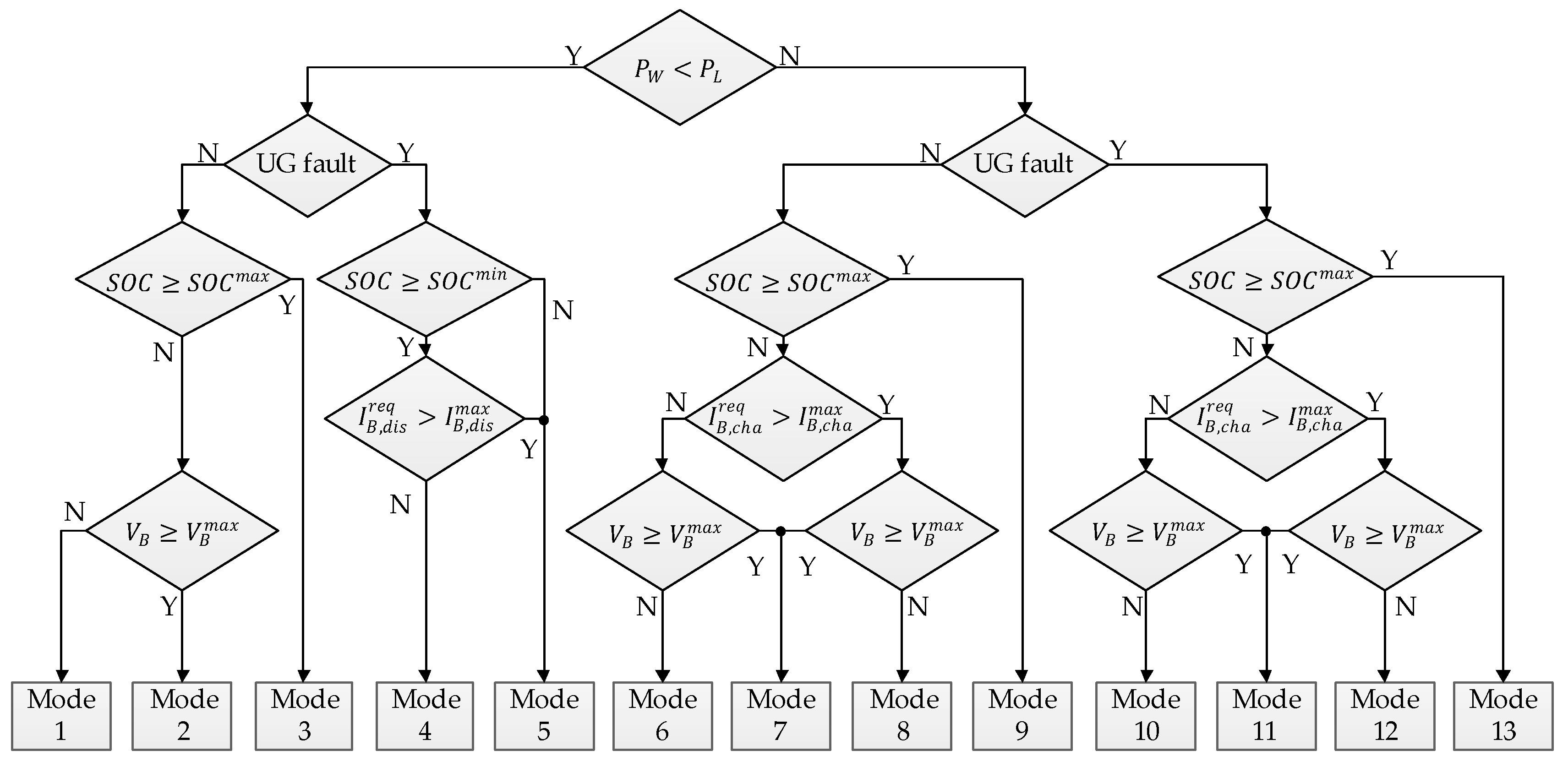
Figure 2 shows the PFCS of DCMG in this study. Based on the correlation of wind power and load demand, UG status, and battery status, thirteen operating modes of DCMG are determined to ensure the system power balance under various conditions. The control and operation of DCMG units according to each operating mode are described in Table 1 in detail. The control mode with an asterisk in the power converter indicates that this converter is in charge of the DCV regulation and system power balance. Symbols in Figure 2 and Table 1 are defined as follows: S O C m a x is the maximum battery state of charge; S O C m i n is the minimum battery state of charge; I B , c h a r e q is the required battery charging current; I B , d i s r e q is the required battery discharging current; I B , c h a m a x is the maximum battery charging current; I B , d i s m a x is the maximum battery discharging current; V B is the battery voltage; V B m a x is the maximum battery voltage; REC denotes rectifier mode; INV denotes inverter mode; DIS denotes disconnected mode in case of UG fault; IDLE denotes idle mode; BVCM denotes battery voltage control mode; BCCM denotes battery current control mode; DCVM-D denotes DCV control mode by battery discharging; DCVM-C denotes DCV control mode by battery charging; SHED denotes LS mode; NC/RECO denotes no change/LR mode; MPPT denotes maximum power point tracking mode.
The entire control and operation of DCMG units corresponding to the thirteen operating modes are explained as follows.
Operating mode 1: The WPGS is operated in the MPPT mode to inject the maximum power from the wind turbine into the DC-link. In this mode, however, the injected power to the DC-link is not sufficient to supply the load demand ( P W < P L ). In this case, the power deficit is compensated by the UG via REC mode operation of AC/DC bidirectional converter. All loads are fed in this operating mode. The battery is controlled in BCCM with the charging current of C / 10 , where C denotes the rated capacity of battery [29]. This charging current level is selected to prevent the battery from overheating and damage.
Operating mode 2: Similar to operating mode 1, the WPGS is operated in the MPPT mode. Because wind power is still not sufficient to supply the load, the DCV is regulated by the UG through AC/DC bidirectional converter with REC mode operation. The only difference from operating mode 1 is that the battery is operated in BVCM in order to avoid the battery damage caused by overvoltage since the battery voltage is greater than its maximum value of V B m a x . All loads are fed in this operating mode.
Operating mode 3: The battery S O C reaches its maximum value of S O C m a x . To prevent the battery from overcharging, the battery operation is switched into IDLE mode. The WPGS is still operated in the MPPT mode and the entire power balance is maintained by the UG. All loads are fed in this operating mode.
Operating mode 4: When a grid fault occurs, the UG is disconnected from DCMG. This mode corresponds to the islanded operating mode of the DCMG. Since the battery S O C is higher than the minimum value of S O C m i n and the required battery discharging current is below the allowable maximum limitation ( I B , d i s r e q I B , d i s m a x ), the battery starts the discharging in DCVM-D mode to regulate the DCV. The WPGS works in the MPPT mode and all loads are fed.
Operating mode 5: This operating mode occurs when the required battery discharging current exceeds its maximum rating ( I B , d i s r e q > I B , d i s m a x ) or the battery S O C is lower than the minimum level ( S O C < S O C m i n ). In order to prevent the battery from overdischarging, in case of I B , d i s r e q > I B , d i s m a x , the battery is discharged with the maximum discharging current, which is achieved by a current limiter in DCVM-D mode. In the latter condition, the battery operation is switched into IDLE mode. In both cases, the battery is not able to regulate the DCV any longer. To avoid system collapse under this critical condition, the LS is activated to disconnect some less important loads. After the LS is completed, there are three possible cases that may happen next as seen from Figure 2. If I B , d i s r e q becomes smaller than I B , d i s m a x after the LS, the system operation is returned to operating mode 4, in which the battery undertakes the task of the DCV control again by means of DCVM-D mode. In another situation, if the remaining load demand becomes lower than the power extracted from the WPGS, and the required battery charging current I B , c h a r e q is smaller than I B , c h a m a x , the system operation is switched into operating mode 10, in which the battery regulates the DCV by DCVM-C mode. Otherwise, the system operation is switched to operating mode 12, in which the WPGS starts to control the DCV by VCM in case that the required battery charging current I B , c h a r e q is greater than I B , c h a m a x . From the above analysis, it is worth mentioning that operating mode 5 only works as a transient mode. After the LS is accomplished at this mode, the system operation is changed to other operating modes, in which the DCV is continuously regulated by the battery or WPGS.
Operating mode 6: This operating mode corresponds to the system operation when the wind power is higher than load demand. If the available power on the DC-link is large enough and the system is stable, the disconnected load in operating mode 5 can be reconnected by using LR algorithm. Since the battery S O C is smaller than the maximum value of S O C m a x , and the battery voltage and required charging current are less than their predefined rating ( V B < V B m a x and I B , c h a r e q I B , c h a m a x ), the battery has a capability to regulate the DCV by using DCVM-C mode. Since the UG is available in this case, the UG may control the DCV through INV mode. However, by considering the unpredictable fault of the UG as well as the variation of wind power, the battery operation with DCVM-C is chosen by priority, which ensures that the battery power can be maintained as high as possible to deal with later critical conditions. As a result, the UG connection system enters IDLE mode, which indicates the UG does not participate in the power exchange of system.
Operating mode 7: Similar to operating mode 6, the wind power is higher than load demand without the UG fault. However, the battery voltage reaches the maximum value of V B m a x . To protect the battery from overvoltage, the battery is charged with BVCM mode, absorbing a portion of the surplus power. The remaining surplus power is absorbed by the UG through INV mode of the bidirectional AC/DC converter.
Operating mode 8: In this mode, the wind power is higher than the load demand without the UG fault. In addition, the required charging current is higher than the maximum rating ( I B , c h a r e q > I B , c h a m a x ). In this case, the battery is controlled by charging it with the maximum charging current of I B , c h a m a x . Similar to operating mode 7, the UG takes charge of the DCV regulation through INV mode of bidirectional AC/DC converter.
Operating mode 9: As the battery S O C reaches the maximum value of S O C m a x , the battery operation is changed into IDLE mode to prevent the battery from overcharging. The UG conducts the role of the DCV regulation by INV mode.
Operating mode 10: This mode corresponds to the islanded operation due to grid fault. In this condition, the battery S O C is smaller than the maximum S O C m a x , also the required charging current and the battery voltage are still less than their maximum rating ( V B < V B m a x and I B , c h a r e q I B , c h a m a x ). In this case, the battery can effectively regulate the DCV in DCVM-C mode by absorbing surplus power.
Operating mode 11: As the battery voltage reaches the maximum value of V B m a x , the battery operation is changed from DCVM-C to BVCM to avoid battery overvoltage. As a result, the authority to control the DCV is released to the power converter of WPGS. For this purpose, the WPGS changes the control mode into VCM in which the DCV is maintained at the nominal value by limiting the injected power from wind to DC-link.
Operating mode 12: This operating mode is the same as the operating mode 8 except for the UG fault. The required battery charging current is higher than the maximum rating ( I B , c h a r e q > I B , c h a m a x ) due to the continuous increase in wind power. As a result, the battery is incapable of regulating the DCV. In this case, BCCM is applied to charge the battery with the maximum charging current and the DCV is kept stable by the WPGS with VCM.
Operating mode 13: When the battery S O C reaches the maximum value of S O C m a x , the battery operation is changed into IDLE mode same with operating mode 9 to avoid overcharging. The WPGS is still in charge of the DCV regulation with VCM.

3.2. Control Scheme of Gird-Connected Converter

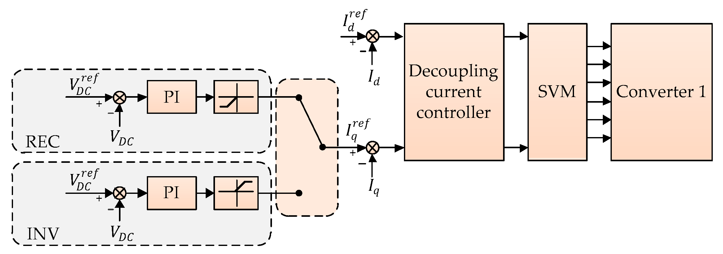
Figure 3 shows the control loops of the bidirectional AC/DC converter (converter 1) used for the UG connection, where V D C is the DCV, I d and I q are currents in the synchronous reference frame (SRF), and superscript ‘ref’ denotes the reference quantity. As seen in Figure 3, the DCV is controlled by an outer loop proportional-integral (PI) controller either in REC or in INV mode. The outer loop DCV controller generates a positive reference current in INV mode, and a negative one in REC mode. The limiters are located after the PI controllers to avoid high undesirable reference currents. A decoupling current controller in the SRF is used for the inner current control loop to ensure zero steady-state tracking error [10,30]. The obtained reference voltages are applied by a space vector modulation (SVM). The IDLE and DIS modes are easily implemented by switching off the connection switch between the UG and DCMG.

3.3. Control Scheme of Wind Power Converter

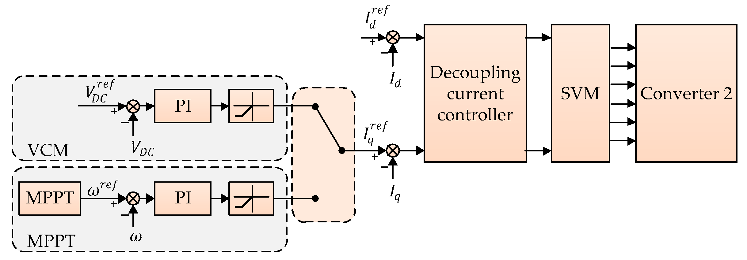
As described in Section 3.1, the WPGS is operated in two operating modes, namely, the MPPT and VCM modes. The MPPT mode is employed to maximize the power extracted from wind while the VCM mode is employed to regulate the DCV in DCMG. Figure 4 shows two control loops of unidirectional AC/DC converter (converter 2) for the WPGS.
The MPPT control algorithm is realized by three cascaded control loops. The outer loop determines the maximum power point using the MPPT algorithm. The output of the MPPT algorithm is the optimal rotor angular speed which is used as the reference of the inner control loop. Inner control loops are composed of two cascaded controllers. The first inner loop controls the rotor angular speed to the reference by using the PI controller. The control output generates the current references which are regulated by subsequent inner control loop based on the synchronous PI decoupling current controller.
In VCM mode, the control loop is cascaded by two control loops. The outer loop is realized to regulate the DCV by the PI controller. The controller outputs are employed as the current references in the inner control loop based on the synchronous PI decoupling current controller.

3.4. Control Scheme of Battery Energy Storage System

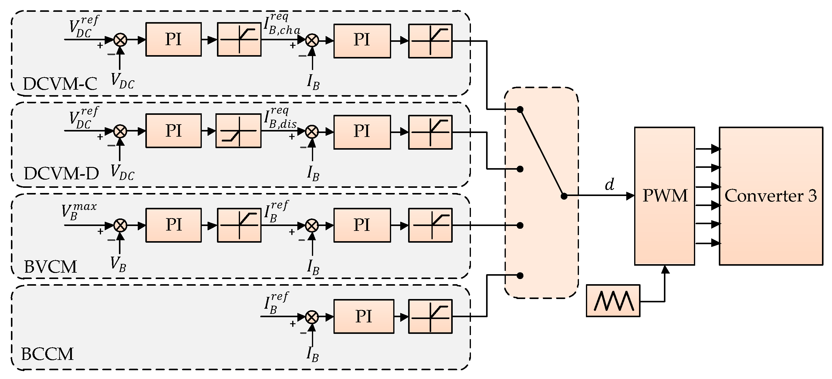
As explained in Section 3.1, the battery-based ESS is operated at five different operating modes, namely, DCVM-C, DCVM-D, BVCM, BCCM, and IDLE mode. The IDLE mode is easily accomplished by opening the connection switch between the battery and DC-link. Figure 5 shows the control loops for four other operating modes of interleaved bidirectional DC/DC converter (converter 3) to interface the battery-based ESS, where I B is the battery current and d is the duty cycle. In both DCVM-C and DCVM-D modes, the DCV control is carried out in the outer control loop. By using the current reference generated from the outer control loop, the inner control loop regulates the charging or discharging currents to guarantee zero tracking errors of the current. In the battery system, the charging current is denoted by a positive value while the discharging current by a negative one.
In BVCM, two control loops are employed to charge the battery with constant voltage. The outer control loop controls the battery at the maximum voltage ( V B m a x ) and the inner control loop is designed in the same way as the DCVM-C and DCVM-D modes. Unlike the above three modes, BCCM is realized by only one current control loop to charge the battery with a desired constant current. In all cases, the output of the current controller is the duty cycle d, which is fed to a pulse width modulation (PWM) block to drive the switches in DC/DC converter (converter 3).

3.5. Load Management Algorithm

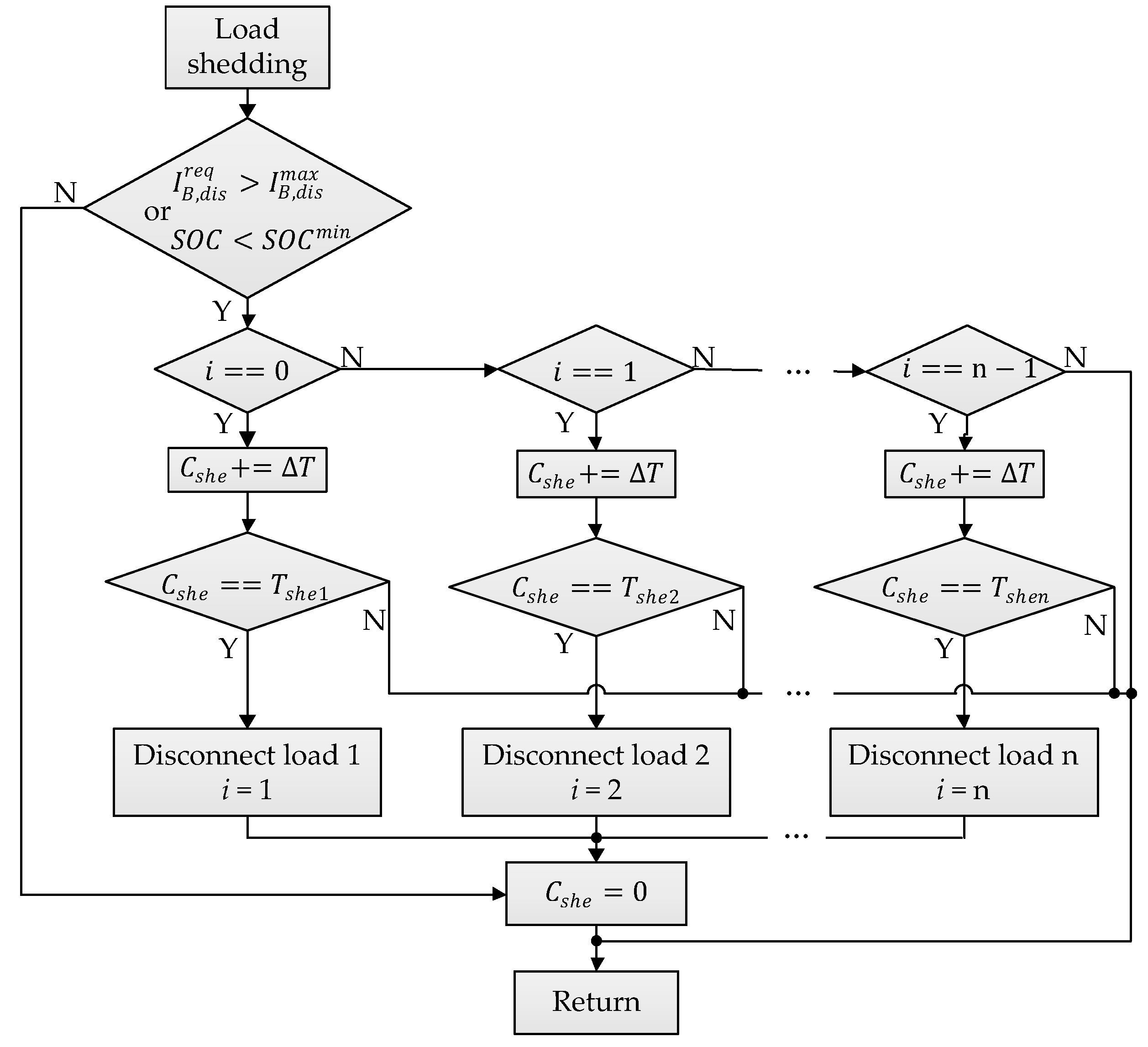
Normally, when the battery is used as the main source to regulate the DCV in case of grid fault, the LS algorithm is not necessary. However, in some critical situations, the LS should be used as the last solution to prevent the system from collapsing. Figure 6 shows the LS algorithm presented in this paper, where i is flag describing the load status, n is the total quantity of load, C s h e , T s h e , and Δ T are the counter, predefined time delay, and step size, respectively.
As explained in operating mode 5, the LS is activated by one of two critical reasons that the required battery discharging current exceeds its maximum rating, or that the battery S O C is lower than the minimum level. The first critical case represents the power deficiency of battery, while the other comes from the insufficiency of energy stored in the battery. For the LS procedure, loads need to be classified into different priority levels to ensure that the load with lower priority should be disconnected first. In this paper, load priority levels are assigned as load 1 < load 2 < … < load n, where load 1 has the lowest priority and load n has the highest priority. Moreover, different shedding time delay levels are added into the LS algorithm to avoid undesirable load disconnection caused by noise. Table 2 shows the description of load status by using the flag i. During the LS, the algorithm checks the value of i to recognize the load which is already disconnected as well as disconnecting the load at next step. As shown in Figure 6, the counter C s h e starts counting up with the step size of Δ T . As soon as C s h e reaches the predefined T s h e , the loads denoted by i are disconnected from DC-link according to Table 2. After load disconnection, C s h e is reset for next operations.
Once the system is back to normal, the disconnected load can be reconnected when necessary. In this paper, UG is assumed as a huge source which can feed any required consumed load. For instance, in case of grid connection, all the disconnected load can be reconnected regardless of the battery and WPGS status. In case of the islanded mode, however, the LR is determined based on the available power on DC-link which can be expressed as
P D C a v a i l = P W + P B , d i s m a x P L
where P D C a v a i l is the available power on DC-link and P B , d i s m a x is the maximum discharging power of the battery. Figure 7 shows the LR algorithm where C r e c and T r e c are the counter and predefined time delay, respectively. When the LR is activated, the algorithm checks the value of i to recognize the reconnecting load. If i is equal to zero, it indicates that no load has been disconnected. As a result, the reconnection algorithm is unnecessary. When i is not zero, the UG status is checked first to reconnect all the loads. In case of the UG fault, P D C a v a i l is computed and is compared with the disconnected load having the highest priority to reconnect it first. The LR algorithm operates similarly to the LS algorithm, with a time delay of T r e c to avoid the effect due to noise. The counter C r e c starts counting and the LR is accomplished when C r e c reaches T r e c .

4. Proposed DC-Link Voltage Restoration Algorithm

In the grid-connected condition, converter 1 operates in the voltage control mode such as REC or INV to regulate the DCV. On the other hand, converter 2 works in the MPPT mode to maximize the extracted power from wind and converter 3 works in BCCM, BVCM, or IDLE to optimize the battery charging sequence. If the grid fault is detected right after fault occurrence, the system operation is quickly switched into the islanded mode in which the WPGS or battery undertakes the role of the DCV regulation. Unfortunately, the grid fault cannot be detected instantly by the fault detection algorithm in some cases due to a large total response time (TRT). In the centralized control approach, TRT is defined as the time interval from the fault occurrence to the final control action by the CC, which includes the fault clearance time, the data transmission time from the fault detection device to the CC, and the processing time for the controller to make a decision. Figure 8 shows TRT period when the grid fault occurs. In Figure 8, the fault clearance time, which consists of sensing time and opening time, is defined as the time duration from the fault occurrence instant to the instant at which DCMG is separated from UG [31]. Because the data transmission time and processing time are negligibly small in comparison with the fault clearance time, the delay of fault detection is considered to be equal to the fault clearance time. During the TRT period, any source or power converter does not serve to regulate the DCV. As a result, the DCV may be increased or decreased rapidly due to the imbalance between the supplied and consumed power, which ends up a catastrophic situation in DCMG. In order to prevent such a circumstance, an effective DCV restoration algorithm based on LECM is proposed in this paper. Figure 9 describes the control structure including the LECM for the proposed DCV restoration. It is worth noting that this paper focuses only on the effect of grid fault detection delays on system stability; the fault detection method is not considered.
In the normal DCMG operation, the CC collects the data from local systems, and then, assigns the proper execution mode (EM) to each LC and load connection/disconnection switches through communication lines as shown in Figure 9, in which EMj (for j = 1, 2, 3, 4) denotes the EM assigned to LCj (for j = 1, 2, 3) and load management system. During the normal operation, LCs are operated according to the EM assigned from the CC as specified in Table 1. For example, the WPGS has either MPPT or VCM as normal control mode as shown in Figure 9. In addition to these normal operation modes, LCs of both the WPGS and battery are also equipped with additional LECMs to deal with abnormal DCV variations caused by the delay of grid fault detection as shown in Figure 9, in which the WPGS has only VCM and the battery has either BCCM or DCVM-D as LECM. The proposed DCV restoration algorithm based on LECM for the WPGS and battery are presented in Figure 10 in detail.
Figure 10a shows the proposed DCV restoration algorithm by the LC2 in the WPGS. In this figure, whereas EM2 denotes the EM from the CC, EM2* denotes the final operating mode which will be applied for converter 2. During the normal control mode, LC2 is operated in the MPPT or VCM corresponding to EM from the CC. Even if the grid fault occurs, the CC fails to assign appropriate operating mode since it cannot recognize the grid fault due to the delay of grid fault detection, which results in a rapid increase of the DCV. As soon as the DCV reaches the predefined maximum level of V D C m a x , the LECM is activated to impose VCM to EM2* regardless of EM from the CC. As a result, the operation of the WPGS is immediately switched into VCM to restore the nominal DCV quickly. As shown in Figure 10a, when the LECM is activated, flag F is set to 1 to indicate the LECM operation. Before the CC recognizes the grid fault due to the delay of grid fault detection, the CC does not change EM2. In this case, flag F is still kept to 1, and consequently, the LECM assigns EM2* to VCM, which indicates that the DCV is regulated with VCM by converter 2 during period of detection delay. Only when the CC finally recognizes the grid fault, the CC assigns a new EM2 to LC2 according to the PFCS in Figure 2. By detecting the change of EM2 from the CC, LC2 resets flag F to 0 to terminate the LECM. Then LC2 starts the normal control mode again by assigning EM2* to new EM2 from the CC.
Figure 10b shows the proposed DCV restoration algorithm by the LC3 in the battery. In this figure, whereas EM3 denotes the EM from the CC, EM3* denotes the final operating mode which will be applied for converter 3. During the normal control mode, LC3 is operated with one among five operating modes according to the EM from the CC. Similarly, in case of the delay of grid fault detection, the DCV can be rapidly decreased due to the power imbalance. As soon as the DCV becomes lower than the first predefined minimum level of V D C m i n 1 , the LECM is triggered to restore the DCV. The restoration of the DCV based on the LECM by LC3 is composed of two stages. During the first stage, flag F1 is set to 1 and EM3* is assigned to BCCM, in which the battery is discharged with the maximum discharging current. By using this discharging mode, the DCV can be recovered toward the nominal value as quickly as possible. As the DCV approaches the second predefined minimum level of V D C m i n 2 which is set to higher level than V D C m i n 1 , the second stage of the LECM is started. During this stage, F2 is set to 1 and EM3* is assigned to DCVM-D, in which the battery regulates the DCV to restore it completely to the nominal value. Similarly, before the CC recognizes the grid fault due to the delay of grid fault detection, flags F1 and F2 are still kept to 1, and consequently, the LECM assigns EM3* to DCVM-D, which indicates that the DCV is regulated with DCVM-D by converter 3 during period of detection delay. Only when the CC finally recognizes the grid fault, the CC assigns a new EM3 to LC3 according to the PFCS in Figure 2. By detecting the change of EM3 from the CC, LC3 resets flags F1 and F2 to 0 to return back to the normal control mode from the LECM. Then, LC3 starts the normal control mode again by assigning EM3* to new EM3 from the CC.

5. Simulation Results

In order to validate the effectiveness of the power flow strategy and the proposed DCV restoration algorithm, simulations were carried out using the PSIM software. Table 3 lists the system parameters used for simulations. Simulations are carried out in three cases which are the grid-connected case, the islanded case, and the case of grid fault detection delay.

5.1. Grid-Connected Case

In the grid-connected case, the UG is used as the main source to maintain the system power balance under different conditions of wind power, battery status, and load demand. The operation conditions used for the simulation are listed in Table 4.
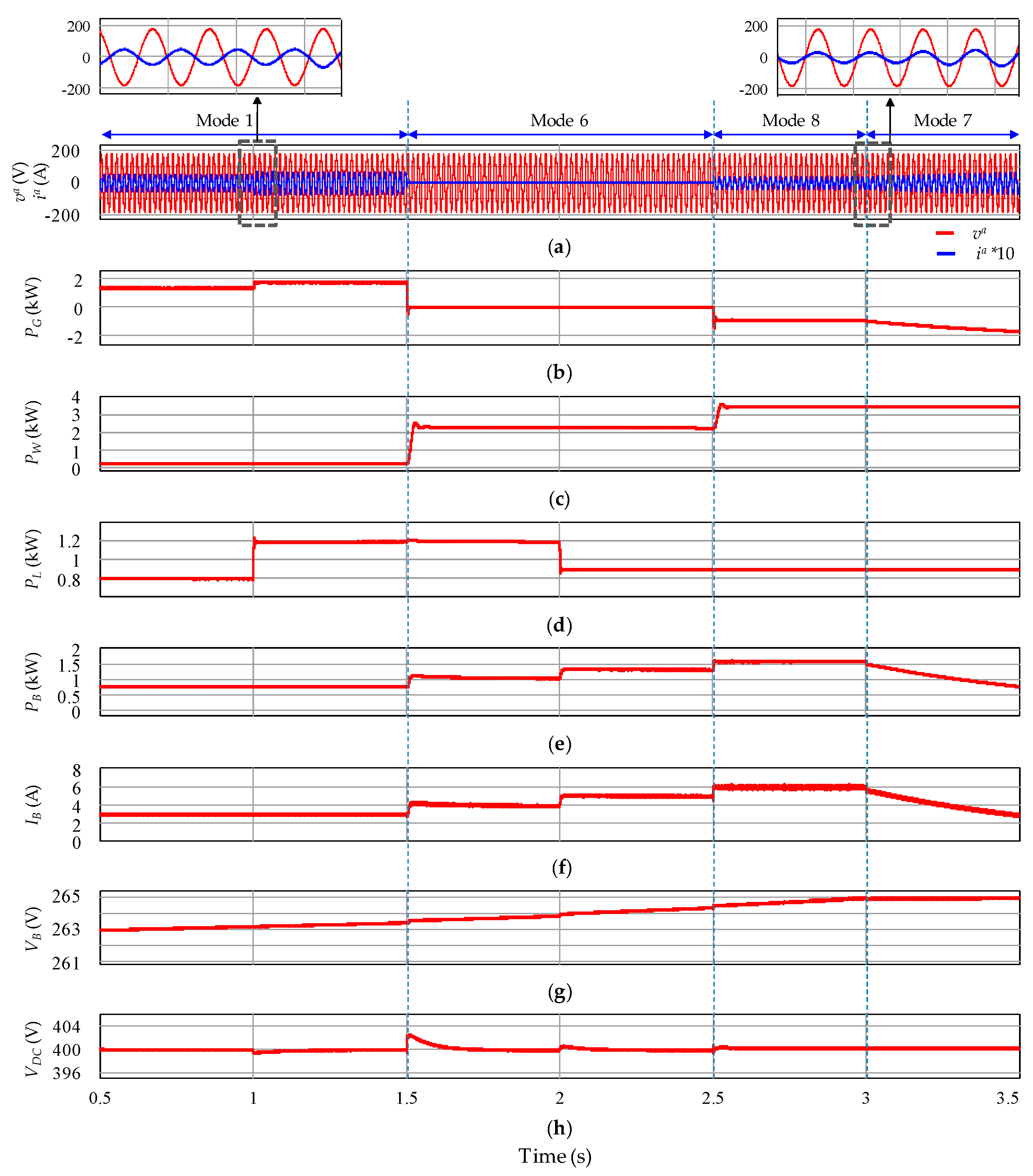
Figure 11 shows the simulation results for the grid-connected case according to the operation conditions in Table 4. Initially, the system runs stably in operating mode 1 at t = 0.5 s. At this instant, the WPGS works in the MPPT mode to deliver approximately 0.25 kW of wind power to DCMG, the battery is charged with a current of 3 A, and two loads (load 2 and load 3) are connected consuming the total power of 0.8 kW. The UG supplies the power deficit to maintain the system power balance.
At t = 1 s, the load demand is suddenly increased because load 4 is switched in. As shown in Figure 11b, the UG increases the supply power to DC-link via REC mode operation of converter 1 to balance the system power exchange. At t = 1.5 s, the generated power from the WPGS is suddenly changed from 0.25 kW to 2.2 kW, which is higher than the load demand ( P L = 1.2 kW). According to the PFCS in Figure 2 and Table 1, the system operation is switched into operating mode 6, in which the battery starts DCVM-C mode to absorb the surplus power in DCMG. In addition, the battery is in charge of regulating the DCV in this operating mode, while the UG is released to IDLE mode. At t = 2 s, load 3 is switched out, which decreases the total load demand to 0.9 kW. Even in this case, the battery keeps balancing the power exchange in DCMG by increasing the charging current as seen in Figure 11f. When the generated wind power is further increased to 3.5 kW at t = 2.5 s and this increased power is not acceptable to battery since the charging current cannot be increased due to the limitation of I B , c h a m a x , the UG connection system is switched from IDLE to INV mode to maintain the system power balance. In this condition, the battery is charged with the maximum charging current of 6 A, in order to avoid overheating and damage. As the battery maximum voltage is reached at around 3 s, the battery operation is changed to BVCM and the power absorbed by battery is gradually reduced. In contrast, the power injected into the UG is gradually increased to keep the system power balance as shown in Figure 11b. These simulation results clearly demonstrate the coordination of the UG and battery during the grid-connected mode.

5.2. Islanded Case

In the islanded case, the DCV is regulated by the coordination operation of the battery and WPGS. Operation conditions used for this simulation are listed in Table 5.
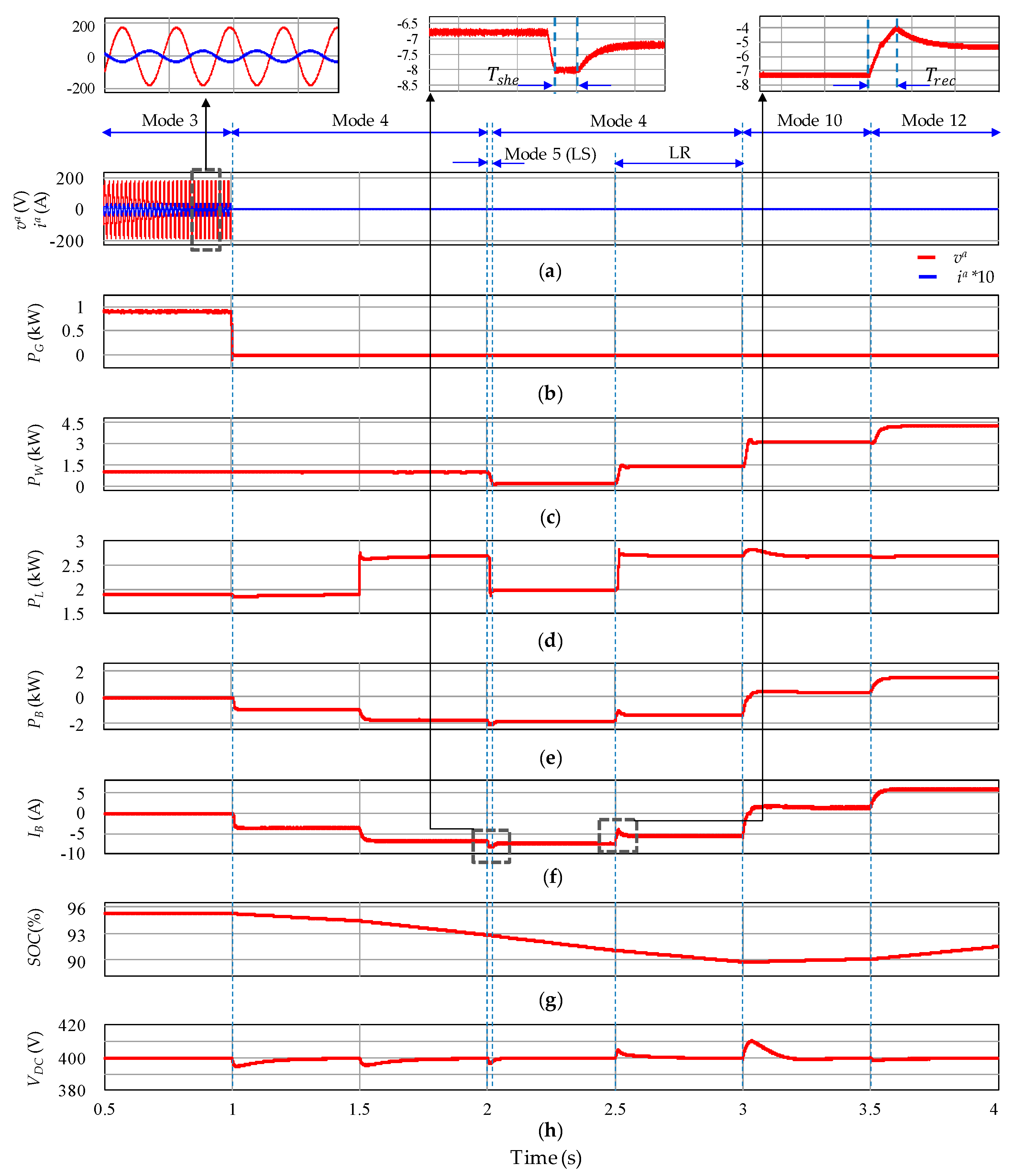
Figure 12 shows the simulation results for the islanded case according to the operation conditions in Table 5. Initially, the system is assumed to operate stably in operating mode 3, in which the DCV is regulated by the UG via REC mode of converter 1. The WPGS is in the MPPT mode, providing approximately 1.1 kW of power to DCMG. Also, it is assumed that the battery is in IDLE mode with the maximum S O C , and DC loads consist of load 1, load 2, load 3, and load 4, which consume the total power of 1.9 kW. w t = 1 s, the grid fault happens and DCMG operation is changed into the islanded mode. If the grid fault is quickly detected, the system operation is changed to operating mode 4, and the battery starts discharging to control the DCV with DCVM-D mode. At t = 1.5 s, load 5 is switched in and the battery increases the discharging power to supply extra load demand as seen in Figure 12e. When the wind power is reduced to 0.2 kW at t = 2 s, the battery tries to increase the discharging current to compensate for the power deficit. In this condition, however, the battery cannot control the DCV any longer due to the discharging current limit of 8 A. In order to prevent DCMG system from collapsing even in this case, operating mode 5 is activated with the LS algorithm. As shown in Figure 6, as soon as the counter C s h e reaches the shedding time delay for load 1, T s h e 1 defined in Table 3, load 1 which has the lowest priority is disconnected. Operating mode 5 lasts only during a small duration and the behavior of battery current during this interval is also shown in the magnified figure in Figure 12. After disconnecting load 1, the total load demand remains at 2 kW. On the other hand, the possible supply power consisting of the WPGS power and the maximum discharging battery power is
P W + P B , d i s m a x = 0.2 + 2 = 2.2   kW
which is higher than the remaining load demand. Therefore, the system operation can be returned to operating mode 4, in which the battery stably controls the DCV after the LS. As the wind power increases from 0.2 kW to 1.5 kW at t = 2.5 s, the available power on DC-link is calculated from (1) as
P D C a v a i l = P W + P B , d i s m a x P L = 1.5 + 2 2 = 1.5   kW .
Because P D C a v a i l is larger than the power of load 1 (0.7 kW), the LR can be activated to reconnect load 1 by using the LR algorithm in Figure 7 and the time delay of T r e c defined in Table 3.
At t = 3 s, as the extracted power from the WPGS is increased to 3.1 kW, which is greater than the power demand of load, the system operation is switched into operating mode 10. Accordingly, the battery operating mode is switched from DCVM-D to DCVM-C to absorb the surplus power. At t = 3.5 s, the WPGS injects the power of 5 kW to DCMG. To maintain the power balance of DCMG system, the battery should continue to absorb the excess power by means of DCVM-C operating mode. However, too large excess power results in the battery overcharging current beyond the maximum value of 6 A. To protect the battery from overheating and damage, the system operation is changed to operating mode 12, in which the battery is charged with the maximum limit of 6 A. Because the battery absorbs only a portion of surplus power in this condition, the WPGS is switched from MPPT to VCM to reduce the power extracted from wind, and consequently, to guarantee the system power balance. As shown in Figure 12, the DCV is effectively regulated and the PFCS satisfactorily works in the presence of variations in wind power and load demand, even during islanded mode.
In order to further demonstrate the effectiveness of the PFCS, a comparison in terms of the DCV regulation performance between this paper and the study of [8] is shown in Table 6. In Table 6, the maximum voltage deviation ratio of the DCV is calculated as
Maximum   voltage   deviation   ratio = Maximum   voltage   deviation Nominal   voltage × 100 .
As shown in Table 6, as compared to the simulation results in Ref [8], the DCV can be regulated at the desirable value with significantly smaller voltage deviation ratio in this paper, in spite of the variations in the generated power from the WPGS and load demand.

5.3. Case of Grid Fault Detection Delay

In this section, simulations are carried out to prove the effectiveness of the proposed DCV restoration scheme for the system stability in case of the grid fault detection delay. The DCV restoration can be achieved either by the battery as shown in Figure 13 and Figure 14, or by the WPGS as shown in Figure 15 and Figure 16. In these simulation results, 0.46 s is used for the fault clearance time.
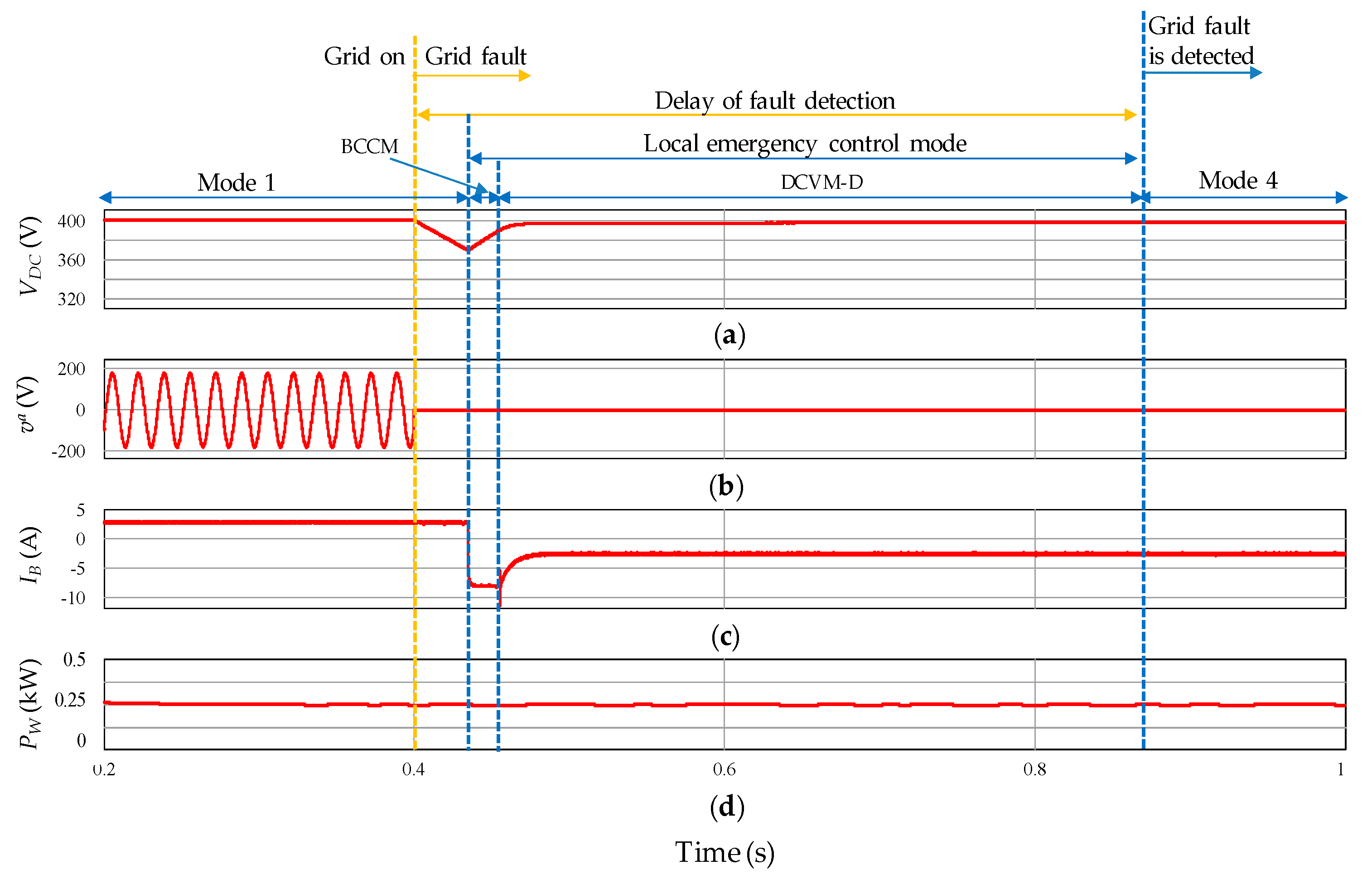
Figure 13 and Figure 14 show the simulation results of the proposed DCV restoration in case of grid fault detection delay during operating mode 1 and operating mode 3, respectively. Before the fault occurs in the UG, DCMG works in operating mode 1 or operating mode 3, in which the system power balance is maintained by the UG via REC mode of converter 1. In both figures, the WPGS is operated in the MPPT mode while the battery is charging in operating mode 1 and is in IDLE mode in operating mode 3. Even though the UG shuts down suddenly at t = 0.4 s, the CC does not recognize it because of the fault detection delay. Consequently, DCMG still operates at operating mode 1 in Figure 13 and operating mode 3 in Figure 14, which results in power imbalance and rapid decrease of the DCV since any power sources do not control the DCV during this period. As soon as the DCV drops to V D C m i n 1 of 370 V, LECM by LC3 is activated. At this instant, the battery operation starts BCCM, discharging the maximum current to restore the DCV quickly. When the DCV reaches V D C m i n 2 of 390 V, the operating mode of battery is automatically switched into DCVM-D to gradually regulate the DCV at the nominal value of 400 V. Once the grid fault is detected with delay at t = 0.55 s, the CC changes the system operation to operating mode 4, terminating LECM by LC3. When DCMG operation returns to the normal mode, the battery continuously controls the DCV by means of DCVM-D mode, with a seamless transition between LECM and the normal mode.
Figure 15 and Figure 16 show the simulation results of the proposed DCV restoration in case of grid fault detection delay during operating mode 8 and operating mode 9, respectively. Before DCMG enters the islanded mode due to the fault occurrence, the UG regulates the DCV stably by absorbing surplus power via INV mode of converter 1. In both figures, the WPGS is operated in the MPPT mode while the battery is charged with the maximum charging current in operating mode 8 and is in IDLE mode in operating mode 9. Similarly, the UG has a fault suddenly at t = 0.4 s. In case of the grid fault detection delay, the CC still uses the UG for the DCV regulation. Under this condition, the UG is not able to absorb excess power any longer, a rapid increase of the DCV and power imbalance are introduced in DCMG. When the DCV reaches the maximum level of 420 V, LECM by LC2 is triggered. As a result, the operating mode of the WPGS is instantly changed to VCM to adjust the DCV to the nominal value of 400 V. Once the grid fault is detected with delay, the CC changes the system operation to operating mode 12 in Figure 15 and operating mode 13 in Figure 16, respectively, according to the PFCS shown in Figure 2. This terminates the LECM by LC2, returning to the normal mode in which the WPGS works with VCM with seamless transition between the LECM and the normal mode.
In order to further demonstrate the effectiveness of the proposed DCV restoration algorithm, the simulation results in case of grid fault detection delay during operating mode 3 without the proposed DCV restoration algorithm are shown in Figure 17. As compared with Figure 14, it is shown that the DCV is rapidly dropped due to the delay of grid fault detection without the proposed DCV restoration algorithm in Figure 17, which confirms the effectiveness of the proposed DCV restoration algorithm.

6. Experimental Results

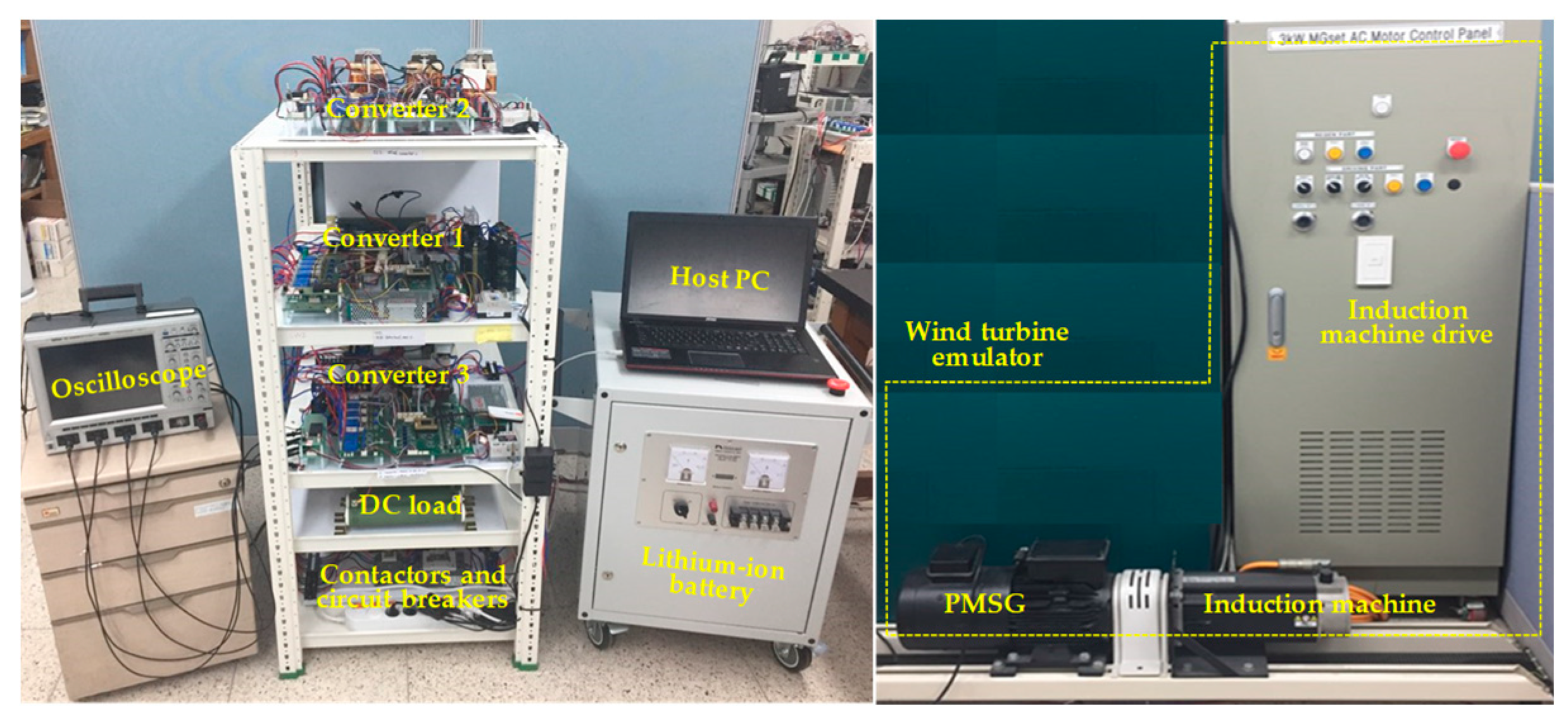
In order to validate the effectiveness of the PFCS and the proposed DCV restoration algorithm, experiments based on the laboratory testbed system were carried out. Figure 18 shows the configuration of the experimental system including three power converters to connect the UG, battery, and WPGS in DCMG. This figure also shows a lithium-ion battery and a wind turbine emulator which is constructed by a PMSG and an induction machine. Similar to the simulations, the experiments are performed in three cases: the grid-connected case, islanded case, and the case of grid fault detection delay.

6.1. Grid-Connected Case

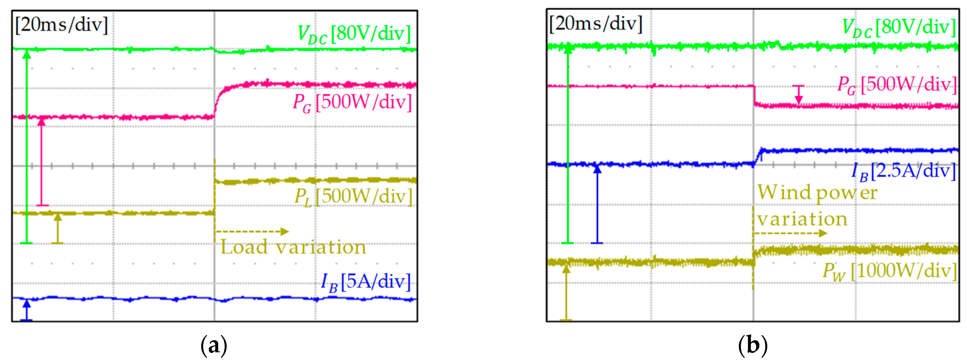
Figure 19 shows the experimental results of DCMG operation for the grid-connected case under the variations of load and wind power. Figure 19a presents DCMG behavior under load power variation. Before load variation, DCMG runs stably in operating mode 1, in which the WPGS is operated in the MPPT mode to inject the maximum power from wind to DCMG and the battery is charged with a constant current of 3 A. The DCV regulation and power balance is achieved by the UG through REC mode of converter 1. At this instant, the load demand is suddenly increased from 0.4 kW to 0.8 kW. To feed extra load demand, the UG increases the supply power to DC-link from 1.2 kW to 1.6 kW as shown in Figure 19a. The battery still works in the same operating mode and the DCV is maintained at the nominal value of 400 V, in spite of load variation.
Figure 19b illustrates the PFCS performance under the mode transition instant. Initially, DCMG is operated in operating mode 6, in which the DCV is controlled by DCVM-C of battery. Meanwhile, the WPGS is running in the MPPT mode and the UG is in IDLE state. When the battery cannot store excess power in DCMG as a result of the increase of wind power from 1.5 kW to 1.9 kW, surplus energy can be used to inject to the UG. In this situation, to ensure the power balance in DCMG, the system enters operating mode 8 and the UG system should be changed from IDLE to INV mode by regulating the DCV. Instead, the battery releases the DCV regulation to the UG system, operating in BCCM with the charging current of 6 A. Despite the wind power variation and resultant operating mode change, it is shown in this figure that the DCV is well maintained at 400 V, with only small transient.

6.2. Islanded Case

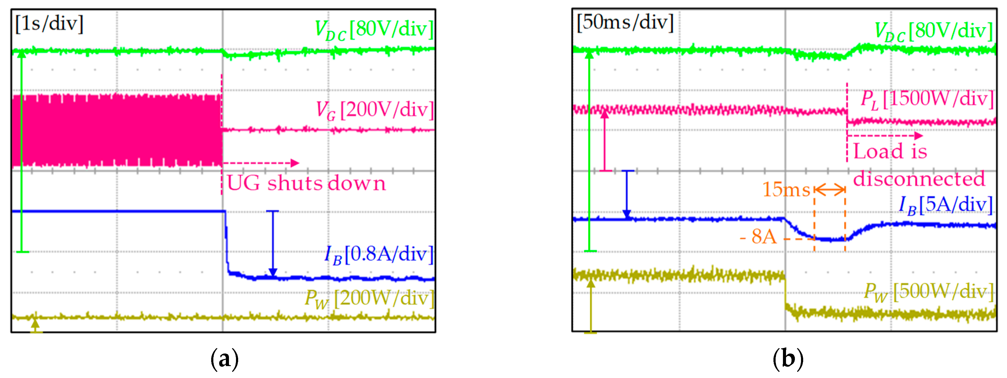
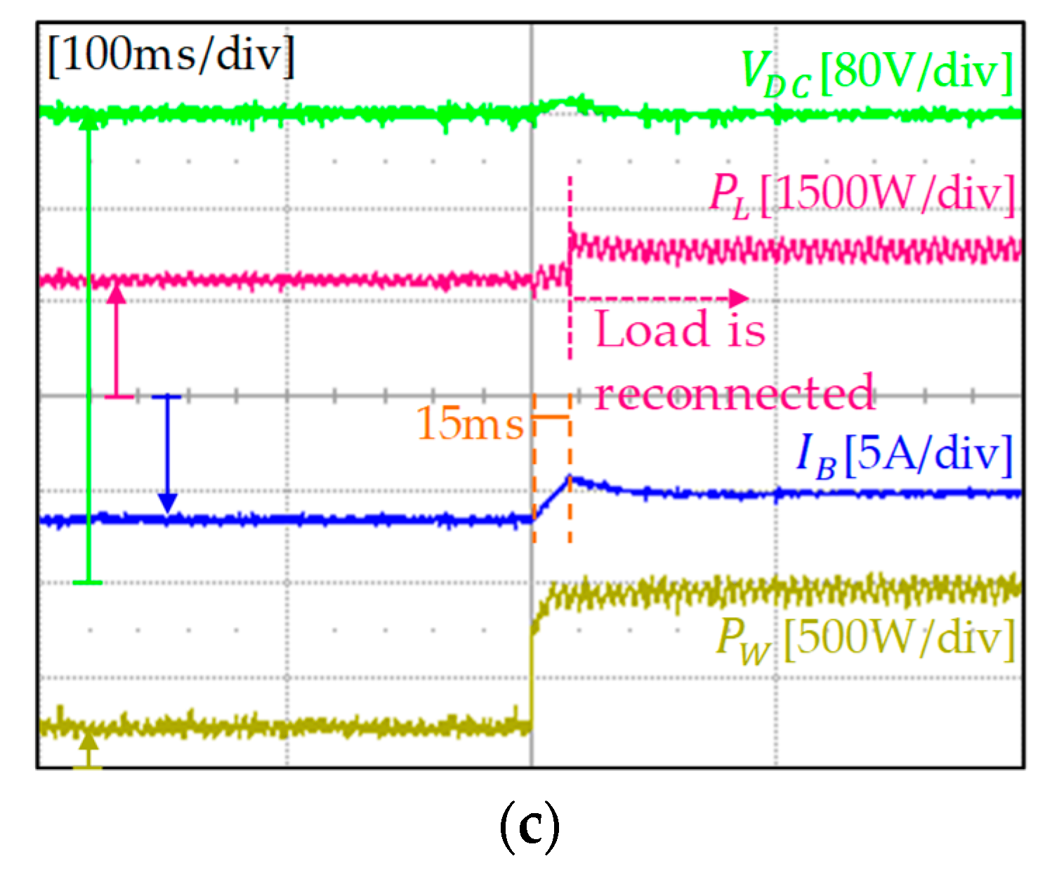
Figure 20 shows the experimental results of DCMG operation for three situations in the islanded case. Figure 20a presents transition results from the grid-connected to islanded mode, Figure 20b shows the results of the LS algorithm, and Figure 20c illustrates the results of LR algorithm, respectively. In Figure 20a, DCMG initially operates stably in operating mode 3. The power balance is maintained by the UG and the battery operation is in IDLE mode. When the UG shuts down abnormally, the system operation is switched to operating mode 4, in which the battery starts DCVM-D mode with discharging current of 1.3 A to compensate the power deficit caused by the UG outage. It is confirmed from Figure 20a that the DCV is stably regulated at 400 V, with only small transient, even under transient conditions in islanded mode.
Figure 20b shows the experimental results for the LS algorithm. At first, the system operates stably in operating mode 4, in which the DCV is controlled by DCVM-D mode of battery and the total load demand is 2.25 kW. As the wind power suddenly drops from 0.75 kW to 0.25 kW, the battery increases its discharging current to compensate this power deficit. Due to the maximum discharging current limit, however, the power balance cannot be achieved by battery discharging. In this case, the LS is inevitable to avoid the system collapse and the DCV reduction. As soon as the LS algorithm is started after 15 ms as seen in Figure 20b, the total load demand is reduced to 1.8 kW by disconnecting load of 0.45 kW. As a result, the battery returns to DCVM-D mode again to regulate the DCV continuously.
Figure 20c shows the experimental results for the LR algorithm. This operation may happen when the wind power in DCMG increases again after the LS. If the wind power increases from 0.25 kW to 0.9 kW after the LS, the CC calculates the available power on DC-link as
P D C a v a i l = P W + P B , d i s m a x P L = 0.9 + 2 1.8 = 1.1   kW .
Because P D C a v a i l is larger than the disconnected load power (0.45 kW) by the LS, this load can be reconnected again after T r e c of 15 ms as shown in Figure 20c. These experimental results coincide well with those of the simulations.

6.3. Case of Grid Fault Detection Delay

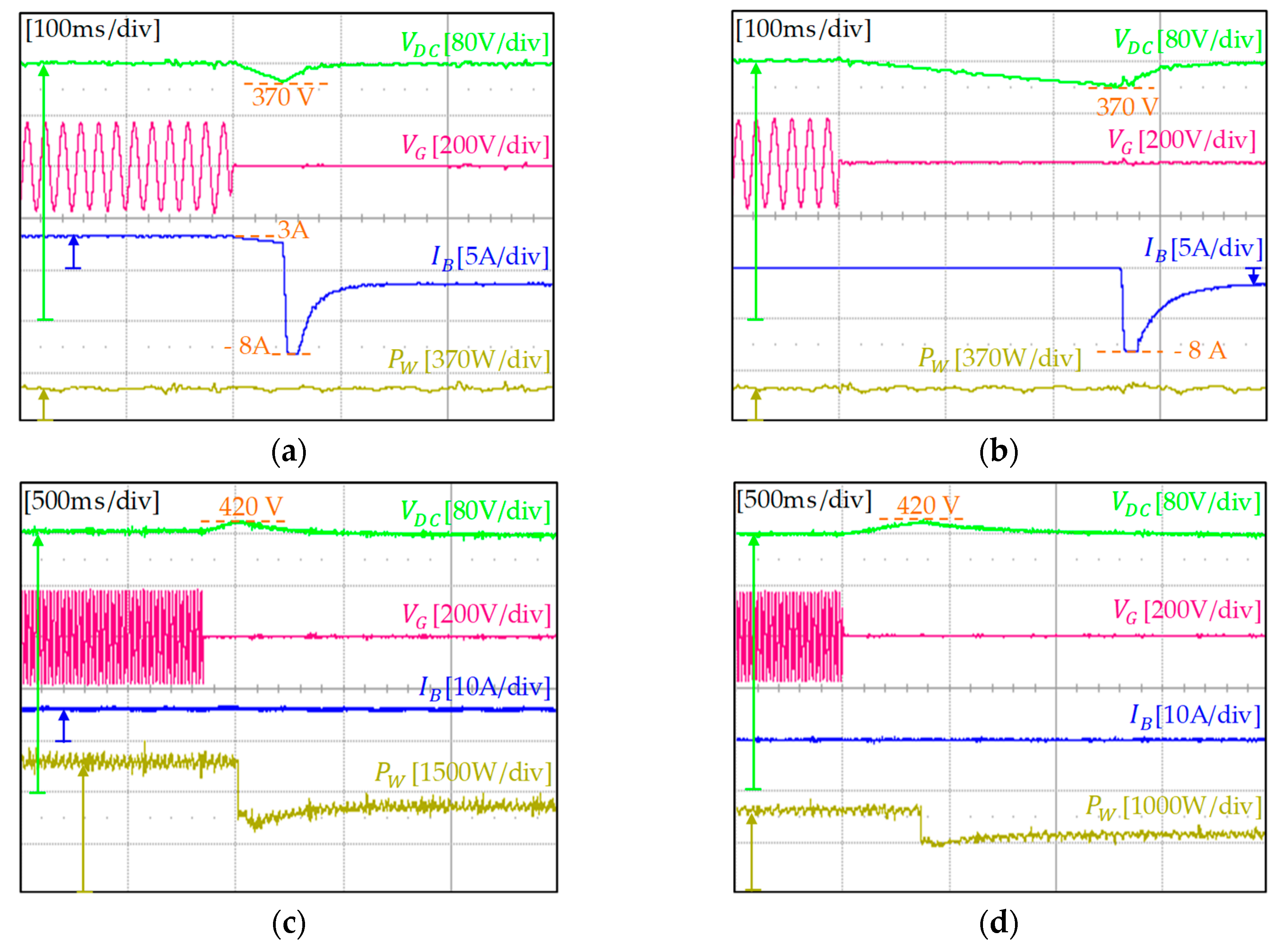
In this section, the experimental results are presented to validate the effectiveness of the proposed DCV restoration scheme. Figure 21 shows the experimental results of the proposed DCV restoration in case of the grid fault detection delay under different operating modes.
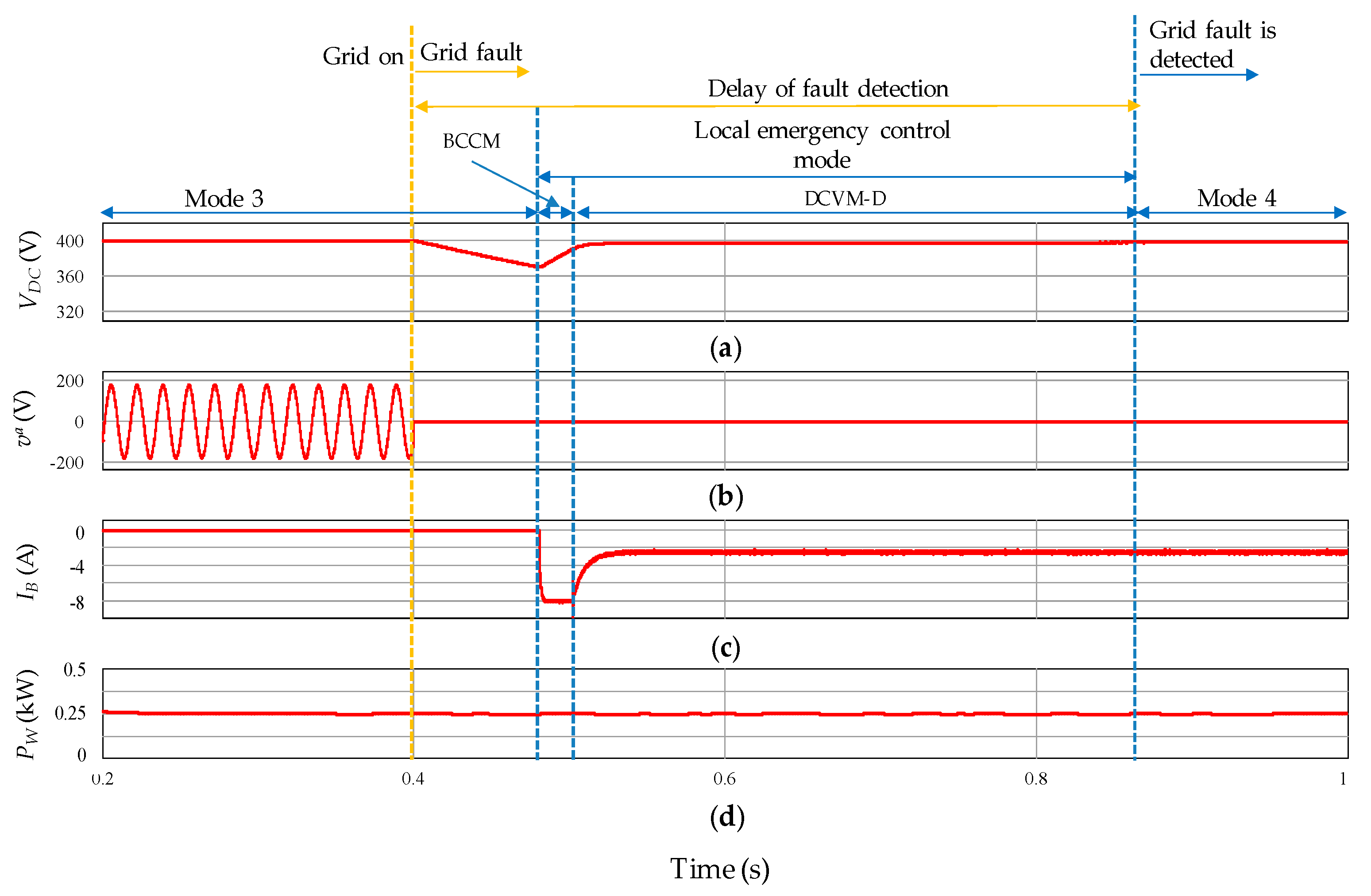
In particular, Figure 21a,b show the experimental results of the proposed DCV restoration implemented by using the battery. Before the UG has a fault, the battery is charging with the current of 3 A in operating mode 1 in Figure 21a and is in IDLE in operating mode 3 in Figure 21b, respectively. As soon as the DCV drops to 370 V, LECM is activated and the battery starts BCCM with the discharging current of 8 A. When the DCV is recovered to 390 V, the battery operation is switched into DCVM-D to gradually regulate the DCV at 400 V. As demonstrated, the experimental results in Figure 21a,b are well matched with the simulation results in Figure 13 and Figure 14.
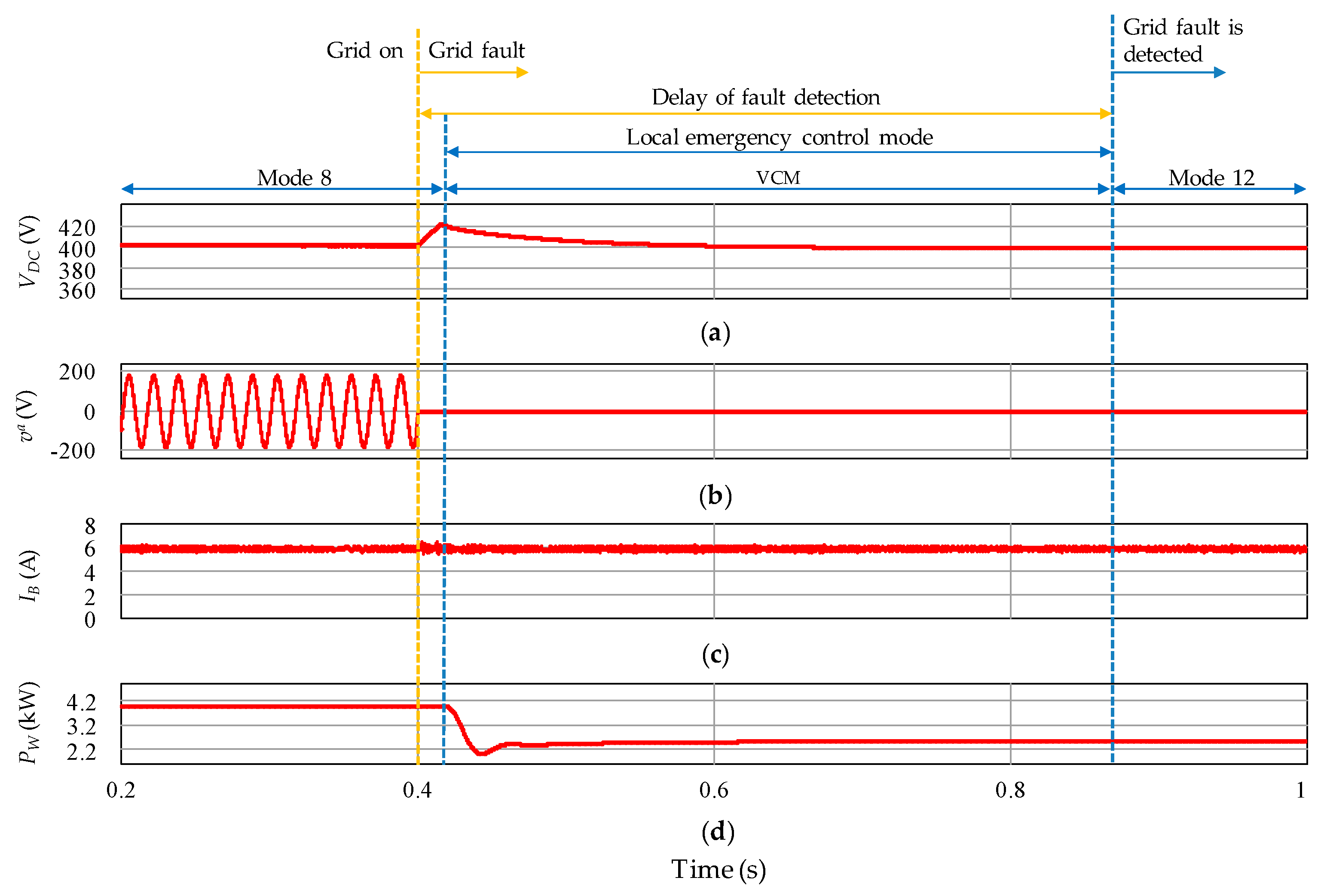
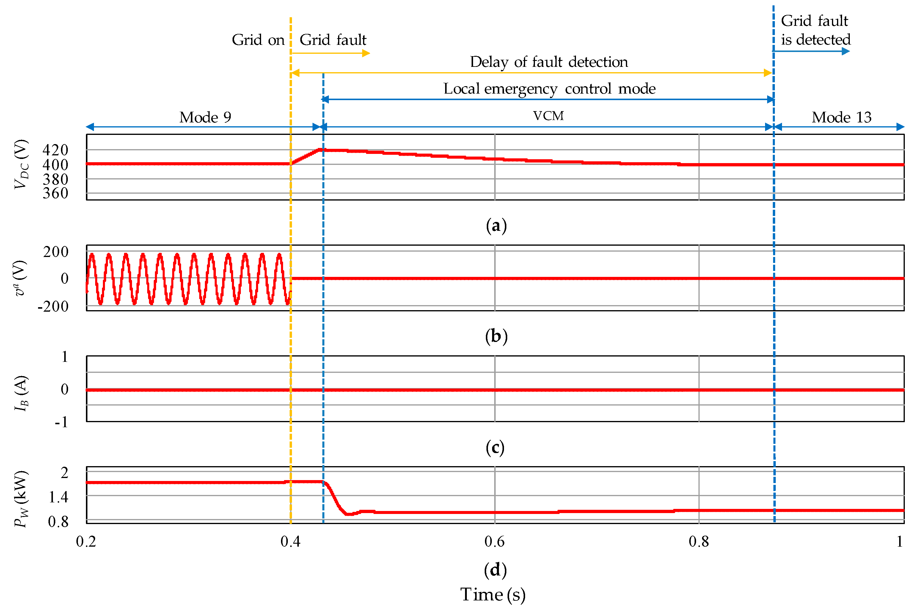
Figure 21c,d show the experimental results of the proposed DCV restoration obtained by using the WPGS. Before the fault occurs in the UG, the battery is charging with the maximum charging current, i.e., 6 A, in operating mode 8 in Figure 21c, and is in IDLE in operating mode 9 in Figure 21d, respectively. Meanwhile, the WPGS works in the MPPT mode to get the maximum power from wind. As explained, the DCV increases rapidly due to the delay of grid fault detection. When the DCV reaches 420 V, LECM is started and the WPGS operation is switched into VCM mode to regulate the DCV at 400 V. These experimental results are also matched well with the simulation results in Figure 15 and Figure 16. As a result, it is confirmed that the DCV which has an essential role in DCMG operation can be restored effectively by using the proposed scheme.

7. Discussion

Based on the simulation and experimental results, the effectiveness of the PFCS and the proposed DCV restoration algorithm for DCMG has been comprehensively validated. The PFCS of DCMG consisting of thirteen operating modes effectively maintains the system power balance both in the grid-connected and islanded modes. Also, the proposed DCV restoration algorithm rapidly recovers the DCV through the LECM operation even in critical cases, which enhances the reliability and expansion of DCMG. However, it is worth noting that the performance of the proposed scheme was evaluated only for DCMG, which is composed of a single battery and a single WPGS. As a result, the proposed scheme can be achieved by a simple control structure. However, since multiple units of ESS and RES are being integrated into DCMGs recently, the implementation of the DCV restoration algorithm in this configuration becomes an important issue in view of the requirement of power-sharing among multiple power systems. DCV restoration in the presence of parallel-connected multiple power systems needs several considerations and modifications in the algorithm; as such, future research works will be devoted to this issue.

8. Conclusions

This paper has presented an effective PFCS based on the centralized control approach and a reliable DCV restoration algorithm for DCMG under grid fault conditions. The main contributions of this paper can be summarized as follows:
(i)
By taking into account the relationship of supply-demand power and the statuses of system units such as the UG, WPGS, and battery, the CC generates thirteen proper operating modes to each LC to effectively deal with various conditions in DCMG. As a result, the stability of DCV and the system power balance can be guaranteed. Moreover, by considering both the grid-connected and islanded modes, a comprehensive performance evaluation for the PFCS was undertaken.
(ii)
In the PFCS, the LS is realized in order to prevent the system from collapsing in critical cases, and the LR is also implemented to reconnect the loads which are disconnected due to power shortages in DCMG. In both the LS and LR algorithms, the time delay is used to avoid undesirable load disconnections or reconnections caused by noises.
(iii)
To prevent the system power imbalance in DCMG caused by the delay of grid fault detection, a reliable DCV restoration algorithm based on the LECM by the LCs of the WPGS and battery-based ESS is also proposed in this paper. By using the proposed scheme, the WPGS or battery instantly starts LECM to restore the DCV rapidly to the nominal value, regardless of the control signals from the CC, as soon as abnormal behavior of the DCV is detected. The experimental tests demonstrate that the proposed scheme restores the DCV to the nominal value within 0.5 s, even in the worst case. Furthermore, after the UG fault is recognized, the proposed scheme transfers DCMG operation from LECM to the normal operating mode, seamlessly and stably.
In order to evaluate the feasibility of the PFCS and the proposed DCV restoration algorithm, a prototype DCMG, consisting of three-phase grid-connected converter, WPGS, and lithium-ion battery-based ESS, was constructed by using 32-bit floating-point digital signal processor (DSP) TMS320F28335 controller. In the experimental setup, the wind turbine emulator consisting of a coupled PMSM-inductor machine and three-phase converter was employed for the WPGS. Comprehensive simulation and experimental results based on the PSIM and DCMG testbed are presented to verify the effectiveness of the PFCS and the proposed DCV restoration algorithm.

Author Contributions

T.V.N. and K.-H.K. conceived the main concept of the control structure and developed the entire system. T.V.N. carried out the research and analyzed the numerical data with guidance from K.-H.K. T.V.N. and K.-H.K. collaborated in the preparation of the manuscript.

Funding

“This research was funded by Seoul Tech (Seoul National University of Science and Technology)” and “The APC was funded by Seoul Tech (Seoul National University of Science and Technology)”.

Acknowledgments

This study was supported by the Advanced Research Project funded by the SeoulTech (Seoul National University of Science and Technology).

Conflicts of Interest

The authors declare no conflict of interest.

Abbreviations

ACAlternating Current
ACMGAC Microgrid
BCCMBattery Current Control Mode
BVCMBattery Voltage Control Mode
CCCentral Controller
CC-CVCurrent Control-Voltage Control
DBSDC-Bus Signaling
DCDirect Current
DCMGDC Microgrid
DCVDC-link Voltage
DCVM-CDC-link Voltage control Mode by battery Charging
DCVM-DDC-link Voltage control Mode by battery Discharging
DGDistributed Generation
DISDisable
DSPDigital Signal Processor
EMExecution Mode
ESSEnergy Storage System
INVInverter
LCLocal Controller
LECMLocal Emergency Control Mode
LRLoad Reconnection
LSLoad Shedding
MGMicrogrid
MPPTMaximum Power Point Tracking
NC/RECONo change/Reconnection
PFCSPower Flow Control Strategy
PIProportional Integral
PMSGPermanent Magnet Synchronous Generator
PWMPulse Width Modulation
RECRectifier
RESRenewable Energy Source
SHEDShedding
S O C State of Charge
SVMSpace Vector Modulation
TRTTotal Response Time
UGUtility Grid
VCMVoltage Control Mode
WPGSWind Power Generation System
C Rated capacity of battery
C r e c Counter of load reconnection
C s h e Counter of load shedding
dDuty cycle
EM2Execution mode from the CC to converter 2 (WPGS)
EM2*Final operating mode applied for converter 2 (WPGS)
EM3Execution mode from the CC to converter 3 (battery)
EM3*Final operating mode applied for converter 3 (battery)
FFlag in the LECM of WPGS
F1, F2Flag in the LECM of battery
iLoad status indication
i a a-phase grid current
I B Battery current
I B r e f Battery current reference
I B , c h a m a x Maximum battery charging current
I B , c h a r e q Required battery charging current
I B , d i s m a x Maximum battery discharging current
I B , d i s r e q Required battery discharging current
I d d-axis current
I d r e f d-axis current reference
I q q-axis current
I q r e f q-axis current reference
LC2Local controller in the WPGS
LC3Local controller in the battery
nTotal quantity of load
P B Battery power
P B , d i s m a x Maximum discharging power of battery
P D C a v a i l Available power on DC-link
P G Output power of UG connection system
P L Load power
P W Output power of WPGS
S O C m a x Maximum battery state of charge
S O C m i n Minimum battery state of charge
T r e c Time delay for load reconnection
T s h e Time delay for load shedding
v a a-phase grid voltage
V B Battery voltage
V B m a x Maximum battery voltage
V D C DC-link voltage
V D C m a x Maximum DC-link voltage in LECM of WPGS
V D C m i n 1 First minimum DC-link voltage in LECM of battery
V D C m i n 2 Second minimum DC-link voltage in LECM of battery
V D C r e f DC-link voltage reference
ω Generator rotor speed
ω r e f Generator rotor speed reference
Δ T Step size

References

  1. Bose, B.K. Global Warming: Energy, Environmental Pollution, and the Impact of Power Electronics. IEEE Ind. Electron. Mag. 2010, 4, 6–17. [Google Scholar] [CrossRef]
  2. Olivares, D.E.; Mehrizi-Sani, A.; Etemadi, A.H.; Cañizares, C.A.; Iravani, R.; Kazerani, M.; Hajimiragha, A.H.; Gomis-Bellmunt, O.; Saeedifard, M.; Palma-Behnke, R.; et al. Trends in Microgrid Control. IEEE Trans. Smart Grid 2014, 5, 1905–1919. [Google Scholar] [CrossRef]
  3. Molderink, A.; Bakker, V.; Bosman, M.G.C.; Hurink, J.L.; Smit, G.J.M. Management and Control of Domestic Smart Grid Technology. IEEE Trans. Smart Grid 2010, 1, 109–119. [Google Scholar] [CrossRef] [Green Version]
  4. Ma, W.; Wang, W.; Wu, X.; Hu, R.; Tang, F.; Zhang, W. Control Strategy of a Hybrid Energy Storage System to Smooth Photovoltaic Power Fluctuations Considering Photovoltaic Output Power Curtailment. Sustainability 2019, 11, 1324. [Google Scholar] [CrossRef]
  5. Salas-Puente, R.A.; Marzal, S.; González-Medina, R.; Figueres, E.; Garcera, G. Power Management of the DC Bus Connected Converters in a Hybrid AC/DC Microgrid Tied to the Main Grid. Energies 2018, 11, 794. [Google Scholar] [CrossRef]
  6. Han, Y.; Chen, W.; Li, Q. Energy Management Strategy Based on Multiple Operating States for a Photovoltaic/Fuel Cell/Energy Storage DC Microgrid. Energies 2017, 10, 136. [Google Scholar] [CrossRef]
  7. Dragičević, T.; Guerrero, J.M.; Vasquez, J.C.; Škrlec, D. Supervisory Control of an Adaptive-Droop Regulated DC Microgrid with Battery Management Capability. IEEE Trans. Power Electron. 2014, 29, 695–706. [Google Scholar] [CrossRef]
  8. Gao, L.; Liu, Y.; Ren, H.; Guerrero, J.M. A DC Microgrid Coordinated Control Strategy Based on Integrator Current-Sharing. Energies 2017, 10, 1116. [Google Scholar] [CrossRef]
  9. Jeong, D.-K.; Kim, H.-S.; Baek, J.-W.; Kim, H.-J.; Jung, J.-H. Autonomous Control Strategy of DC Microgrid for Islanding Mode Using Power Line Communication. Energies 2018, 11, 924. [Google Scholar] [CrossRef]
  10. Mohammadi, F. Power Management Strategy in Multi-Terminal VSC-HVDC System. In Proceedings of the 4th National Conference on Applied Research in Electrical, Mechanical, Computer and IT Engineering, Tehran, Iran, 4 October 2018. [Google Scholar]
  11. Lee, S.-J.; Choi, J.-Y.; Lee, H.-J.; Won, D.-J. Distributed Coordination Control Strategy for a Multi-Microgrid Based on a Consensus Algorithm. Energies 2017, 10, 1017. [Google Scholar] [CrossRef]
  12. Nguyen, T.-L.; Guillo-Sansano, E.; Syed, M.H.; Nguyen, V.-H.; Blair, S.M.; Reguera, L.; Tran, Q.-T.; Caire, R.; Burt, G.M.; Gavriluta, C.; et al. Multi-Agent System with Plug and Play Feature for Distributed Secondary Control in Microgrid—Controller and Power Hardware-in-the-Loop Implementation. Energies 2018, 11, 3253. [Google Scholar] [CrossRef]
  13. Yue, J.; Hu, Z.; Li, C.; Vasquez, J.C.; Guerrero, J.M. Economic Power Schedule and Transactive Energy through an Intelligent Centralized Energy Management System for a DC Residential Distribution System. Energies 2017, 10, 916. [Google Scholar] [CrossRef]
  14. Kaur, A.; Kaushal, J.; Basak, P. A Review on Microgrid Central Controller. Renew. Sustain. Energy Rev. 2016, 55, 338–345. [Google Scholar] [CrossRef]
  15. Dragičević, T.; Lu, X.; Vasquez, J.C.; Guerrero, J.M. DC Microgrids-Part I: A Review of Control Strategies and Stabilization Techniques. IEEE Trans. Power Electron. 2016, 31, 4876–4891. [Google Scholar]
  16. Geng, Y.; Hou, M.; Zhang, L.; Dong, F.; Jin, Z. An Improved Voltage Control Strategy for DC Microgrid with Hybrid Storage System. In Proceedings of the 2018 13th IEEE Conference on Industrial Electronics and Applications (ICIEA), Wuhan, China, 31 May–2 June 2018; pp. 958–962. [Google Scholar]
  17. Sanjeev, P.; Padhy, N.P.; Agarwal, P. Peak Energy Management Using Renewable Integrated DC Microgrid. IEEE Trans. Smart Grid 2018, 9, 4906–4917. [Google Scholar] [CrossRef]
  18. Salas-Puente, R.; Marzal, S.; González-Medina, R.; Figueres, E.; Garcera, G. Experimental Study of a Centralized Control Strategy of a DC Microgrid Working in Grid Connected Mode. Energies 2017, 10, 1627. [Google Scholar] [CrossRef]
  19. Liu, B.; Zhuo, F.; Zhu, Y.; Yi, H. System Operation and Energy Management of a Renewable Energy-Based DC Micro-Grid for High Penetration Depth Application. IEEE Trans. Smart Grid 2015, 6, 1147–1155. [Google Scholar] [CrossRef]
  20. Chen, M.; Ma, S.; Wan, H.; Wu, J.; Jiang, Y. Distributed Control Strategy for DC Microgrids of Photovoltaic Energy Storage Systems in Off-Grid Operation. Energies 2018, 11, 2637. [Google Scholar] [CrossRef]
  21. Sanjeev, P.; Padhy, N.P.; Agarwal, P. A New Architecture for DC Microgrids using Supercapacitor. In Proceedings of the 2018 9th IEEE International Symposium on Power Electronics for Distributed Generation Systems (PEDG), Charlotte, NC, USA, 25–28 June 2018; pp. 1–5. [Google Scholar]
  22. Li, F.; Li, R.; Zhou, F. Microgrid Technology and Engineering Application, 1st ed.; Elsevier: London, UK, 2015; pp. 59–60. [Google Scholar]
  23. Sanjeev, P.; Padhy, N.P.; Agarwal, P. Autonomous Power Control and Management between Standalone DC Microgrids. IEEE Trans. Ind. Inform. 2018, 14, 2941–2950. [Google Scholar] [CrossRef]
  24. Xu, L.; Chen, D. Control and Operation of a DC Microgrid with Variable Generation and Energy Storage. IEEE Trans. Power Deliv. 2011, 26, 2513–2522. [Google Scholar] [CrossRef]
  25. Khamis, A.; Xu, Y.; Dong, Z.Y.; Zhang, R. Faster Detection of Microgrid Islanding Events using an Adaptive Ensemble Classifier. IEEE Trans. Smart Grid 2018, 9, 1889–1899. [Google Scholar] [CrossRef]
  26. Kim, M.-S.; Haider, R.; Cho, G.-J.; Kim, C.-H.; Won, C.-Y.; Chai, J.-S. Comprehensive Review of Islanding Detection Methods for Distributed Generation Systems. Energies 2019, 12, 837. [Google Scholar] [CrossRef]
  27. Ahmad, K.N.E.K.; Selvaraj, J.; Rahim, N.A. A Review of the Islanding Detection Methods in Grid-Connected PV Inverters. Renew. Sustain. Energy Rev. 2013, 21, 756–766. [Google Scholar] [CrossRef]
  28. Zhang, J.; Lai, J.-S.; Kim, R.-Y.; Yu, W. High-Power Density Design of a Soft-Switching High-Power Bidirectional dc–dc Converter. IEEE Trans. Power Electron. 2007, 22, 1145–1153. [Google Scholar] [CrossRef]
  29. Wong, Y.S.; Hurley, W.G.; Wölfle, W.H. Charge Regimes for Valve-Regulated Lead-Acid Batteries: Performance Overview Inclusive of Temperature Compensation. J. Power Sources 2008, 183, 783–791. [Google Scholar] [CrossRef]
  30. Bahrani, B.; Karimi, A.; Rey, B.; Rufer, A. Decoupled dq-Current Control of Grid-Tied Voltage Source Converters Using Nonparametric Models. IEEE Trans. Ind. Electron. 2013, 60, 1356–1366. [Google Scholar] [CrossRef]
  31. IEEE. IEEE Standard for Interconnection and Interoperability of Distributed Energy Resources with Associated Electric Power Systems Interfaces; IEEE Std.1547; IEEE: New York, NY, USA, 2018. [Google Scholar]
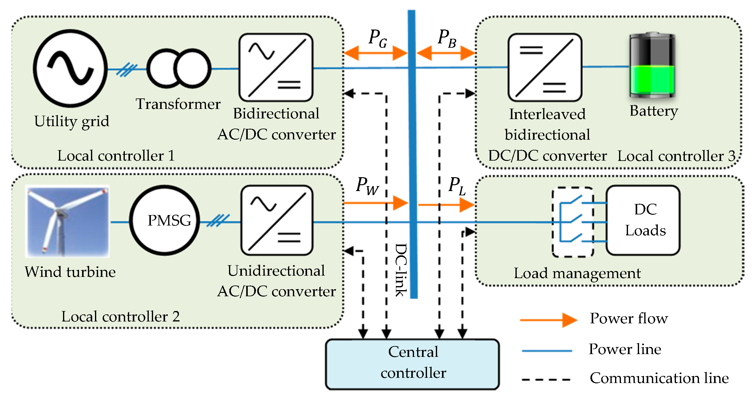
Figure 1. Configuration of DCMG.
Sustainability 11 03781 g001
Figure 2. PFCS of DCMG.
Sustainability 11 03781 g002
Figure 3. Control loops of converter 1 used for UG connection.
Sustainability 11 03781 g003
Figure 4. Control loops of converter 2 for WPGS.
Sustainability 11 03781 g004
Figure 5. Control loops of converter 3 for battery-based ESS.
Sustainability 11 03781 g005
Figure 6. LS algorithm.
Sustainability 11 03781 g006
Figure 7. LR algorithm.
Sustainability 11 03781 g007
Figure 8. TRT period.
Sustainability 11 03781 g008
Figure 9. Control structure including LECM for DCV restoration.
Sustainability 11 03781 g009
Figure 10. Proposed DCV restoration algorithms. (a) By LC2; (b) By LC3.
Sustainability 11 03781 g010
Figure 11. Simulation results for grid-connected case. (a) a-phase grid voltage and current; (b) Output power of UG connection system; (c) Output power of WPGS; (d) Load power; (e) Battery power; (f) Battery current; (g) Battery voltage; (h) DCV.
Sustainability 11 03781 g011
Figure 12. Simulation results for islanded case. (a) a-phase grid voltage and current; (b) Output power of UG connection system; (c) Output power of WPGS; (d) Load power; (e) Battery power; (f) Battery current; (g) Battery S O C ; (h) DCV.
Sustainability 11 03781 g012
Figure 13. Simulation results of the proposed DCV restoration in case of grid fault detection delay during operating mode 1. (a) DCV; (b) a-phase grid voltage; (c) Battery current; (d) Output power of WPGS.
Sustainability 11 03781 g013
Figure 14. Simulation results of the proposed DCV restoration in case of grid fault detection delay during operating mode 3. (a) DCV; (b) a-phase grid voltage; (c) Battery current; (d) Output power of WPGS.
Sustainability 11 03781 g014
Figure 15. Simulation results of the proposed DCV restoration in case of grid fault detection delay during operating mode 8. (a) DCV; (b) a-phase grid voltage; (c) Battery current; (d) Output power of WPGS.
Sustainability 11 03781 g015
Figure 16. Simulation results of the proposed DCV restoration in case of grid fault detection delay during operating mode 9. (a) DCV; (b) a-phase grid voltage; (c) Battery current; (d) Output power of WPGS.
Sustainability 11 03781 g016
Figure 17. Simulation results in case of grid fault detection delay during operating mode 3 without the proposed DCV restoration algorithm. (a) DCV; (b) a-phase grid voltage; (c) Battery current; (d) Output power of WPGS.
Sustainability 11 03781 g017
Figure 18. Configuration of the experimental system.
Sustainability 11 03781 g018
Figure 19. Experimental results for grid-connected case. (a) Load variation at mode 1; (b) Transition from mode 6 to mode 8.
Sustainability 11 03781 g019
Figure 20. Experimental results for islanded case. (a) Transition from grid-connected to islanded mode; (b) LS; (c) LR.
Sustainability 11 03781 g020aSustainability 11 03781 g020b
Figure 21. Experimental results of the proposed DCV restoration in case of grid fault detection delay. (a) During operating mode 1; (b) During operating mode 3; (c) During operating mode 8; (d) During operating mode 9.
Sustainability 11 03781 g021
Table 1. Detailed description of thirteen operating modes in PFCS.
ModeWPGSLoadUG Connection SystemBattery-Based ESS
Mode 1MPPTNC/RECOREC*BCCM
Mode 2MPPTNC/RECOREC*BVCM
Mode 3MPPTNC/RECOREC*IDLE
Mode 4MPPTNC/RECODISDCVM-D*
Mode 5MPPTSHEDDISIDLE/DCVM-D*
Mode 6MPPTNC/RECOIDLEDCVM-C*
Mode 7MPPTNC/RECOINV*BVCM
Mode 8MPPTNC/RECOINV*BCCM
Mode 9MPPTNC/RECOINV*IDLE
Mode 10MPPTNC/RECODISDCVM-C*
Mode 11VCM*NC/RECODISBVCM
Mode 12VCM*NC/RECODISBCCM
Mode 13VCM*NC/RECODISIDLE
Table 2. Description of load status.
i0123n
Indication No load
is disconnected
Load 1
( P L 1 )
is disconnected
Load 2, 1
( P L 2 , P L 1 )
are disconnected
Load 3, 2, 1
( P L 3 , P L 2 , P L 1 )
are disconnected
All loads
( P L n , , P L 2 , P L 1 )
are disconnected
Table 3. System parameters of DCMG.
Unit ParameterSymbolValue
UGUtility grid voltage V G r m s 220 V
Grid frequency F G 60 Hz
Inverter-side inductance of LCL filter L 2 1.7 mH
Grid-side inductance of LCL filter L 1 0.9 mH
Filter capacitance of LCL filter C f 4.5 µF
Transformer Y / Δ T380/220 V
PMSG for wind turbineStator resistance R S 0.64 Ω
dq-axis inductance L d q 0.82 mH
Number of pole pairs P 6
Inertia J 0.111 kgm2
Flux linkage ψ 0.18 Wb
Battery Maximum discharging power P B , d i s m a x 2 kW
Maximum voltage V B m a x 265 V
Maximum charging current I B , c h a m a x 6 A
Maximum discharging current I B , d i s m a x 8 A
Maximum S O C S O C m a x 95 %
Minimum S O C S O C m i n 20 %
Rated capacity C 30 Ah
DC-linkVoltage V D C 400 V
Capacitance C D C 4 mF
Maximum DCV V D C m a x 420 V
First minimum DCV V D C m i n 1 370 V
Second minimum DCV V D C m i n 2 390 V
Load Power of load 1 P L 1 0.7 kW
Power of load 2 P L 2 0.5 kW
Power of load 3 P L 3 0.3 kW
Power of load 4 P L 4 0.4 kW
Power of load 5 P L 5 0.8 kW
Shedding time delay for load 1 T s h e 1 15 ms
Shedding time delay for load 2 T s h e 2 30 ms
Shedding time delay for load 3 T s h e 3 45 ms
Shedding time delay for load 4 T s h e 4 60 ms
Shedding time delay for load 5 T s h e 5 75 ms
Time delay for LR T r e c 15 ms
Priority level: Load 1 < Load 2 < Load 3 < Load 4 < Load 5
Table 4. Operation conditions for simulation test in grid-connected case.
Operation ConditionsTime (s)
1Load 4 is switched in.1
2Wind power increases from 0.25 kW to 2.2 kW.1.5
3Load 3 is switched out.2
4Wind power increases from 2.2 kW to 3.5 kW.2.5
5Battery voltage reaches its maximum value.3
Table 5. Operation conditions for simulation test in islanded case.
Operation ConditionsTime (s)
1Grid fault occurs.1
2Load 5 is switched in.1.5
3Wind power decreases from 1.1 kW to 0.2 kW.2
4Wind power increases from 0.2 kW to 1.5 kW.2.5
5Wind power increases from 1.5 kW to 3.1 kW.3
6Wind power increases from 3.1 kW to 5.0 kW.3.5
Table 6. Comparison of the DCV regulation performance.
Study in Ref [8] This Paper
Maximum voltage deviation ratio of the DCV in grid-connected case1.84%0.75%
Maximum voltage deviation ratio of the DCV in islanded case5.26%2.5%