Abstract
Driving mode switches of hybrid vehicles are significant events. Due to the different dynamic characteristics of the engine, motor, and wet clutch, it is difficult to coordinate torque fluctuations caused by mode switches. This paper focused on a control strategy for driving mode switches of plug-in hybrid electric vehicles (PHEVs) with a multi-disk wet clutch. First, the dynamic model of the PHEV was established, and a rule-based control strategy was proposed to divide the working mode regions and distribute the torque between engine and motor. Second, the dual fuzzy control strategy for a wet clutch and the coordinated torque control strategy for driving mode switches were proposed. The dual fuzzy logic control system consisted of the initial pulse-width modulation (PWM)’s duty cycle control and the changing rate of the PWM’s duty cycle control. Considering the difference in the dynamic characteristics between engine, motor, and wet clutch, a coordinated control strategy for the driving mode switches of PHEVs was put forward. Third, simulations of driving mode switches between pure electric driving mode and only engine driving mode were conducted. The results showed that the proposed control strategy could reduce the torque ripple and the jerk of the vehicle, completely satisfying the requirements of China. Finally, the control strategy for the motor-assisted engine starting process was tested on the bench. The experiment results indicated that the proposed control strategy was effective.
1. Introduction
The energy crisis and environmental pollution are becoming more and more serious. The energy demand from road traffic is increasingly growing, and the emissions due to road traffic are almost always an important fraction of the total emissions of a territory [1,2]. In this context, plug-in hybrid electric vehicles (PHEVs) have attracted significant research attention because they assume an essential role in decreasing fuel consumption and reducing pollutant emissions [3,4,5]. Plug-in hybrid electric vehicles have two core control problems: energy management in the steady state process and coordinated torque control in the dynamic process. With the development of intelligent transportation and intelligent network vehicle technology, such as vision and LIDAR [6], vehicle trajectory prediction [7], driving cognition [8], and V2X technology [9], the first problem will be solved very well. At that time, the second problem will become the key factor restricting the development of plug-in hybrid electric vehicles. PHEVs have many driving modes such as pure electrical driving mode (Ev-mode), only engine driving mode (Eng-mode), hybrid driving mode (Hev-mode), and charging mode (Char-mode). Due to the different dynamic characteristics of the engine, motor, and wet clutch, driving mode switches from one to another cause torque fluctuations, which deteriorate the riding comfort. Therefore, it is necessary to control the dynamic process of driving mode switches effectively to reach a coordinated work state between engine, motor, and clutch [10,11,12].
Many studies have been conducted about mode switching control problems. Tong et al. [13,14] defined the coordinated control issue of mode switching for the first time, and proposed a coordinated torque control strategy for “the engine torque open-loop control, dynamic engine torque estimation, and motor torque compensation”. The Toyota hybrid system (THS), which adopts planetary gear sets, uses the motor to compensate torque difference after calculating the engine’s torque. This system can eliminate torque ripple during mode switching [15,16]. Yang et al. [17,18] designed two adaptive controllers to make the motor implement the demand torque and compensate the diesel engine error torque. Su et al. [19] established the engine torque estimation (ETE) model. Then, a motor torque compensation control based on the engine ripple torque estimation was developed. The above research studies consider the difference of the dynamic response characteristic between the engine and motor, and use the motor to compensate the engine torque. However, the role of the clutch during the mode switching process has been neglected.
Several research works have taken the clutch dynamic characteristic into account when designing a torque coordination control strategy. Minh and Rashid [20] and Beck et al. [21] applied two model predictive controllers (MPCs) to regulate the speeds and torques for fast clutch engagement when HEV-mode switches. Sun et al. proposed a novel torque coordination control strategy for a single-shaft parallel HEV based on only one model predictive controller (MPC), and the clutch torque is used as an optimized variable in MPC [22]. Wang et al. proposed a novel mode switch control strategy based on an MPC algorithm to control the immediate torques of the engine, the motor, and the automatic clutch [23]. In the above works, the MPC algorithm was used to regulate speeds or torques of the engine, motor, or clutch. However, the above coordinated control strategies based on MPC are hard to apply to real-time control because of the computation burden.
From the above analysis, the authors knew that it was necessary to conduct research on a real-time control strategy for mode switches while considering the clutch dynamic characteristic. In this paper, a new type of PHEV with a multi-disk wet clutch was taken as the research object; the torque coordination control during the braking mode switch for this vehicle has been completed by Yang et al. [24]. This paper focused on the real time control strategy for the driving mode switches of this vehicle. First, the dynamic model of the PHEV was established, and a rule-based control strategy was proposed to divide the working mode regions and distribute the torque between engine and motor. Then, the dual fuzzy control strategy for a wet clutch and the coordinated torque control strategy for driving mode switches were proposed. Finally, to verify the proposed control strategy, the simulations and bench test were conducted.
The outline of this paper is as follows. The structure and dynamic models of the driving system are analyzed in Section 2. The torque distribution strategy is provided in Section 3. The control strategy for driving mode switches is proposed in Section 4. The simulation and bench test results are presented in Section 5. Finally, the conclusions are discussed in Section 6.
2. Structure and Dynamic Model of the Driving System
2.1. PHEV Structure
This study focused on a single-shaft parallel plug-in hybrid electric vehicle. The PHEV’s powertrain and driveline systems are shown in Figure 1. These systems include a gasoline engine, an integrated starter and generator motor (ISG motor), a lithium-ion battery pack, a multi-disk wet clutch, an electro-hydraulic proportional valve (EPV), a continuously variable transmission (CVT), and an electric oil pump. The vehicle works in different modes by controlling the state of the engine, the ISG motor, and the wet clutch. The clutch control unit regulates the wet clutch’s oil pressure by controlling the EPV’s pulse-width modulation (PWM) duty cycle. The electric oil pump provides oil to the wet clutch and the CVT.
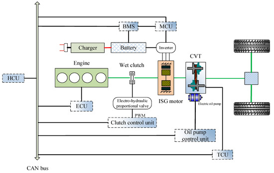
Figure 1.
The plug-in hybrid electric vehicle (PHEV)’s powertrain and driveline systems.
2.2. Dynamic Model of the Driving System
2.2.1. Driving System Model
The simplified drive system is depicted in Figure 2, where , , , , and represent the engine torque, the motor torque, the clutch torque, the vehicle load torque, and the engine dragging torque, respectively; and are the angular speed of engine and the ISG motor, respectively, whereas and denote the equivalent engine rotary inertia and the equivalent vehicle rotary inertia, respectively.
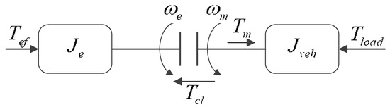
Figure 2.
The simplified drive system.
The driving system may operate under one of the following driving modes: (1) Ev-mode, (2) Eng-mode, (3) Hev-mode, and (4) Char-mode.
Mode 1. Ev-mode
When the required torque or the vehicle’s velocity is low, the vehicle generally works in Ev-mode. Only the ISG motor provides the power.
Mode 2. Motor-assisted engine starting
When the vehicle’s driving mode is changed from Ev-mode to Eng-mode, Hev-mode, or Char-mode, the engine must be started. The wet clutch must be engaged during this process. To describe the model switching process more clearly, the clutch engagement process is divided into four stages: (1) Clutch free travel stage; (2) Clutch sliding stage; (3) Speed synchronization stage; and (4) Completely locked stage.
- (1)
- Clutch free travel stageAt this stage, the clutch is not contacted, so the engine speed is zero. This stage can be represented by the following equation:
- (2)
- Clutch sliding stageAt this stage, the clutch begins to contact, it begins to transfer torque. When the clutch torque is less than the engine dragging torque, the engine speed is zero; and when the clutch torque is greater than the engine dragging torque, the engine speed will increase. This stage can be expressed by the following equation:
- (3)
- (Speed synchronization stageAt this stage, the engine has been started, and the engine control unit adjusts the engine speed until rad/s. This stage can be represented by the following equation:
- (4)
- Completely locked stageAt this stage, engine speed regulation has been completed, the engine speed and the motor speed have reached synchronization, and the engine has begun to provide torque for the power system. During this stage, the clutch needs rapid combination. This stage can be represented by the following equation:
Generally, the engine dragging torque is a function of engine speed, but it is greatly affected by temperature. The engine dragging torque was obtained from the bench test system, shown in Figure 3. This system mainly includes the engine, the frequency conversion motor (FC-motor), and the speed-torque sensor (ST-sensor). The engine is dragged by the FC-motor, and the ST-sensor is used to test the engine’s dragging torque and engine speed. The following were selected as testing temperatures: −20 °C, −15 °C, −10 °C, −5 °C, 0 °C, 5 °C, 10 °C, 15 °C, 20 °C, and 25 °C. At each testing temperature, the engine running was dragged at 200 r/min, 400 r/min 600 r/min, 800 r/min, 1000 r/min, and 1200 r/min, respectively. Then, the engine’s dragging torque was tested at each testing temperature and running speed. Finally, the map of the engine’s dragging torque was obtained, as is shown in Figure 4.
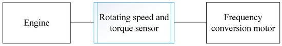
Figure 3.
The engine dragging torque’s bench test system.
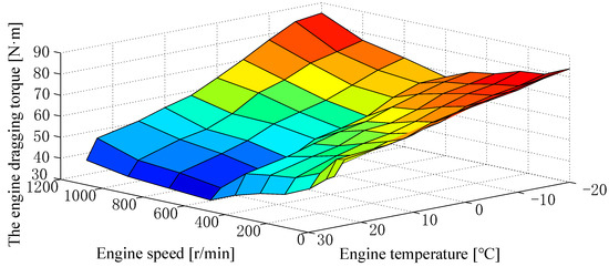
Figure 4.
The engine dragging torque.
2.2.2. Clutch Model
The clutch’s engagement process has great influence on the mode switching. To achieve good clutch control, a hydraulic clutch system controlled by an electro-hydraulic proportional valve (EPV) was designed. This hydraulic system is shown in Figure 5. This system mainly consists of an EPV, one-way valves, sensors, an accumulator, a relief valve, an auxiliary motor, and a controller. The controller regulates the average current of the EPV by controlling the duty cycle of the PWM, thus achieving an accurate, continuous, and linear control of the clutch oil pressure.
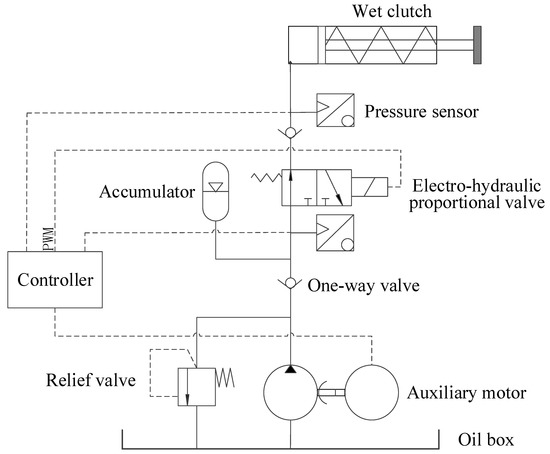
Figure 5.
The hydraulic clutch system diagram controlled by an electro-hydraulic proportional valve (EPV).
The structure diagram of the EPV is shown in Figure 6. When the proportional solenoid is electrified, the spool moves to the right, and the outlet valve opens to the maximum opening position. With the increase of load, the outlet pressure of the EPV increases. The outlet pressure acts on the right end of the valve core through the feedback channel. When the load is small, the outlet pressure is lower than the setting pressure, which is set by the output force of the plunger (), then, the opening of the outlet valve does not change. When the output pressure exceeds the setting pressure, the spool moves to the left under the action of pressure difference, and the outlet valve’s opening is reduced. This ensures that the outlet pressure () remains unchanged and is proportional to the average current of the proportional solenoid.
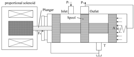
Figure 6.
The structure diagram of the EPV.
The force balance equation of the spool is expressed as follows:
where is the output force of the plunger, is the outlet pressure, A is the feedback area of the outlet pressure, M is the quality of the spool, x is the displacement of the spool, is the pre-compression of the spool, is the stiffness of the spring, is the hydrodynamic elastic stiffness, is the viscous damping coefficient of the spool, and is the transient hydrodynamic damping coefficient.
The equation of the proportional solenoid is as follows:
where is the current/force gain coefficient of the proportional solenoid and is the input current of the proportional solenoid.
The equation for the relationship of EPV’s outlet flow and outlet pressure is as follows:
where is the inlet pressure, is the gradient of the valve port’s area, is the flow coefficient of the valve port, and is the fluid density.
After linearization, the following can be expressed:
where is the flow’s gain coefficient, ; is the pressure’s gain coefficient, ; ; is the displacement of the spool’s stable working point; and and are the pressure value of the spool’s stable working point, respectively.
According to the continuity equation of flow, when the load flow is zero, then the following can be expressed:
where is the total volume of liquid in the controlled chamber of the outlet and is the bulk modulus of oil.
According to Equations (9) and (10),
Subsequent to the application of the Laplace transform to Equations (6), (7), and (11), respectively, the following is obtained:
The transfer function of the EPV is expressed as follows:
3. Torque Distribution Strategy
The plug-in hybrid electric vehicle has many different kinds of working modes, so it is necessary to divide the working mode into different regions [25,26]. A rule-based control strategy for this PHEV is proposed. The working region was divided for optimal system efficiency, as is shown in Figure 7. In the figure, is the engine launch speed limit, is the upper limit torque when only electric driving, is the lower limit torque when only engine driving is the upper limit torque when only engine driving, is the optimized set speed, and is the lower limit of discharge. is the required torque. According to Figure 6, the judgment conditions of each driving mode and the target torques are shown in Table 1 and Table 2, respectively.
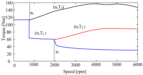
Figure 7.
The division of the PHEV’s working region.

Table 1.
Judgment conditions of driving mode.
Table 2.
Target torques of the engine and motor.
As is shown in Table 1, the motor speed, the battery’s state of charge (SOC) and the required torque are the boundary conditions of mode switching. When the motor speed, battery’s SOC and required torque meet a certain operating mode area, the hybrid system will switch from the current operating mode to the selected operating mode.
According to the required torque, the operating mode, and the structure of the hybrid system, the target torque of the engine and the motor in different operating modes can be obtained. The details are shown in the Table 2. is the corresponding torque of the engine’s optimal operation point, is the maximum torque of motor, and is the vehicle’s charging torque.
4. Control Strategy for Driving Mode Switches
In the process of driving mode switching, it is difficult to control the engine because of its long response time and non-linearity compared with the motor. When the Ev-mode is switched to Eng-mode, Hev-mode, or Char-mode, the motor must start the engine. The combustion is unstable at the initial stage of the engine ignition, resulting in a large fluctuation of engine torque. Thus, the torque of the hybrid system changes dramatically, and then transfers this to the whole vehicle, affecting the vehicle’s ride comfort [27,28]. Therefore, it is necessary to coordinate the torque of the engine, the motor, and the wet clutch. The whole process of mode switching is illustrated in Figure 8. The driver’s driving intention is recognized according to the signals from the accelerator pedal and the braking pedal, after which the required torque of the vehicle is obtained. The engine’s and motor’s target torques will be obtained by the torque distribution strategy. The target working mode will be confirmed according to the required torque, SOC of battery, and vehicle’s velocity. The mode switch is judged by comparing the current working mode with the target one. If the mode switch occurs, the coordinated torque control strategy is adopted to control the engine, the motor, and the wet clutch. After the coordinated control process is finished, the working mode will be updated and the mode switch process is finished.
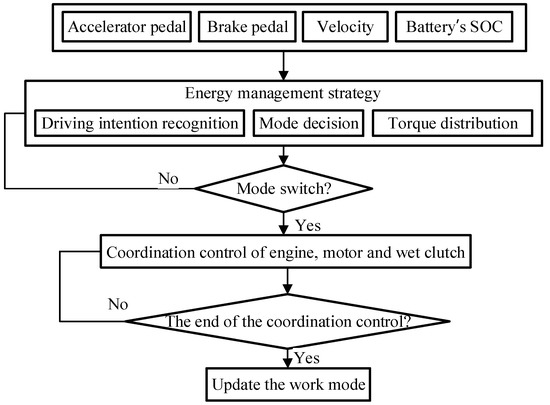
Figure 8.
The flowchart of the driving mode switch control.
4.1. Control of the Wet Clutch
The plug-in hybrid power system must start the engine quickly by engaging the clutch during the process of the motor starting the engine. In this process, part of the motor torque is used to drive the normal running of the vehicle, and part of the motor torque is provided to drag the engine by the sliding torque of the wet multi-plate clutch. During this process, the motor torque and clutch torque should be coordinated to ensure that the engine starting process will not cause excessive torque fluctuation.
In this process, the clutch torque can be calculated by [11]:
where is the clutch torque, is the clutch pressure, and are the speed of the motor and engine, respectively, is the friction factor, is the friction pair’s number, is the area of friction plate, and is the clutch plate’s effective radius.
The clutch’s oil pressure is controlled by the EPV. The average current of the EPV’s proportional solenoid can be calculated by [29]:
where is the PWM’s duty cycle, is the PWM’s period, is the steady voltage, is the equivalent resistance of the proportional solenoid, and is the time constant of the EPV.
According to Equation (14), the clutch torque is a function of the engaging oil pressure, which is actually the outlet pressure of the EPV. When the spool of the EPV is in equilibrium state, the outlet pressure of the EPV is proportional to the average current of the proportional solenoid [30]. According to Equation (15), after keeping the PWM’s period () unchanged, the average current of the proportional solenoid is proportional to the PWM’s duty cycle (), and when the PWM’s duty cycle () varies from 0 to 100%, the average current of the proportional solenoid is changed from 0 to the steady current (). Therefore, the wet clutch’s torque control is converted into the control of the PWM’s duty cycle ().
In the process of controlling the clutch engagement, the control of the initial PWM’s duty cycle () and the changing rate of the PWM’s duty cycle () in sliding stage are the most important, which has a great influence on the engagement performance of the wet clutch. The PWM’s duty cycle of the EPV is controlled through a fuzzy logic control.
A. The fuzzy control of the initial PWM’s duty cycle.
When the clutch controller receives the engagement instruction, the controller outputs the initial PWM’s duty cycle to the proportional solenoid, the spool moves, the outlet valve opens, and the clutch’s oil pressure rises rapidly to build the initial oil pressure. At the same time, the increment of the initial PWM’s duty cycle is calculated according to the accelerator pedal’s opening and the change rate of the accelerator pedal’s opening . Then, the initial PWM’s duty cycle can be obtained by the following:
Fuzzy control is applied to calculate the increment of the PWM’s duty cycle . and are selected as the inputs of the fuzzy controller, is selected as the output of the fuzzy controller. All of the parameters of , , and are divided into seven fuzzy language sets: VS (very small), S (small), MS (minor small), M (medium), MB (middle big), B (big), and VB (very big). The fuzzy logic control rule of the increment of the initial PWM’s duty cycle is shown in Table 3. When the driver steps on the accelerator pedal deeply and quickly, the increment of the initial PWM’s duty cycle must be increased to meet the requirement for strong power. When the driver steps on the accelerator pedal slowly, the increment of the initial PWM’s duty cycle must be declined to meet the ride comfort.
Table 3.
Fuzzy control rule of the increment of the initial pulse-width modulation (PWM)’s duty cycle.
B. The fuzzy control of the PWM’s duty cycle changing rate in sliding stage.
After the initial PWM’s duty cycle reaches the target value, the wet clutch establishes its initial oil pressure. The main and driven plates of the clutch start contacting, sliding, and transmitting torque. During the sliding stage, the driver’s intention and the degree of the clutch’s engagement should be determined, and the fuzzy control is used to set the appropriate changing rate of the PWM’s duty cycle.
The change rate of the accelerator pedal’s opening and the speed difference of the clutch plate are selected as this fuzzy controller’s inputs, whereas the output of the fuzzy controller is the changing rate of the PWM’s duty cycle. , and are also divided into seven fuzzy language sets: VS, S, MS, M, MB, B, and VB. The fuzzy rules of the changing rate of the PWM’s duty cycle are shown in Table 4. In the sliding stage, when the accelerator pedal is stepped on quickly, the driver wants to complete the mode switching process as fast as possible, so the changing rate of the PWM’s duty cycle should be increased quickly. If the driver steps on the accelerator pedal slowly, the comfort should be fully considered; thus, the PWM’s duty cycle should be increased slowly. If is large, which indicates that the clutch engagement degree is low, then should be declined to meet the ride comfort; if is small, which means that the clutch engagement degree is high and the clutch oil pressure is high, then should be increased to reduce the sliding friction work as much as possible.
Table 4.
Fuzzy rules of the PWM’s duty cycle changing rate.
The integrated fuzzy control system of the PWM’s duty cycle control of the EPV is shown in Figure 9. As shown, the wet clutch’s oil pressure is controlled by regulating the EPV’s duty cycle through the dual fuzzy control.
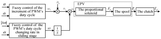
Figure 9.
The integrated fuzzy control system of the PWM’s duty cycle control.
4.2. Driving Mode Switch’s Control Strategy
The driving mode switch can be divided into two types: the mode switch with clutch engagement and the mode switch without clutch engagement. The first type takes place mainly while the Ev-mode is switched to Eng-mode, Hev-mode, or Char-mode. This type of mode switch requires motor-assisted engine starting. During the motor-assisted engine starting process, to achieve continuous control of the clutch oil pressure, to ensure that the clutch is engaged rapidly and smoothly, and to take advantage of the fast response characteristic of the motor, the dual fuzzy control strategy for a wet clutch and the coordinated torque control strategy are combined to control the clutch’s oil pressure and the motor’s torque. Taking the switching from Ev-mode to Eng-mode as an example, the combined control strategy for motor-assisted engine starting is shown in Figure 10. The combined control strategy for the switch from Ev-mode to Eng-mode- can be divided into four stages.
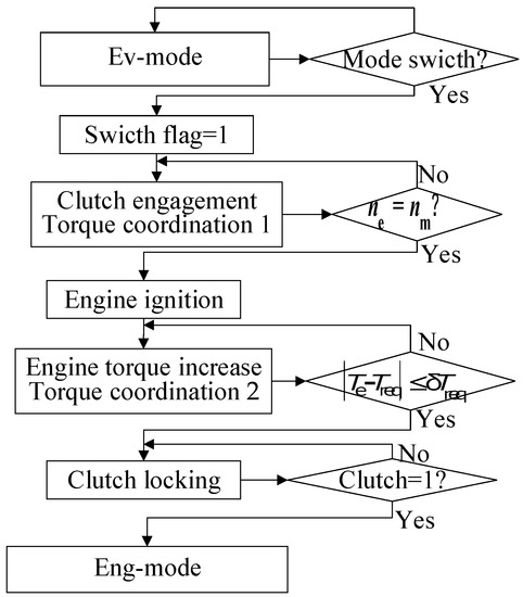
Figure 10.
The control flow from Ev-mode to Eng-mode.
The first stage: the whole vehicle runs in Ev-mode, the engine is closed, the clutch is separated, and only the motor provides the normal driving torque of the vehicle:
The second stage: the vehicle control unit (VCU) sends out the mode switch command, and the clutch begins to engage. The engagement oil pressure is controlled by regulating the PWM’s duty cycle through the above fuzzy control system. At this time, the motor must not only provide the torque to run the vehicle, but also must provide the clutch torque to start the engine:
The third stage: when the engine speed is equal to the motor speed, the engine is ignited. Since the output torque of the ignition engine is not stable, it is necessary to use the motor to obtain torque compensation:
The fourth stage: when the absolute value of the difference between the engine torque and the engine target torque is within the allowable range , the clutch is locked, the motor is closed, the vehicle is driven by the engine alone, and the mode switching ends:
The type of the mode switch without clutch engagement takes place mainly while the Eng-mode, Hev-mode or Char-mode is switched to Ev-mode, or the mode switches between Eng-mode, Hev-mode, and Char-mode. The torque coordinated control strategy for this type of mode switch is that the torque changing rate of the engine is controlled and the motor provides torque compensation. Taking the switching from Eng-mode to Ev-mode as an example, the torque coordination control strategy for the clutch separation process is shown in Figure 11.
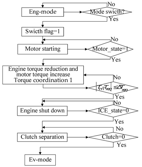
Figure 11.
The control flow from Eng-mode to Ev-mode.
The torque coordinated control strategy for this switch can be divided into three stages.
The first stage: the whole vehicle runs in Eng-mode, the motor is closed, the clutch is locked, and only the engine provides the driving torque of the vehicle:
The second stage: at the beginning of mode switching, the motor control unit (MCU) receives the instructions from the vehicle controller, and the motor starts. The motor gradually increases the torque while the engine gradually decreases the torque, and the torque decreasing rate of the engine is controlled:
where is the engine torque before change, is the target engine torque after changing rate control, is the changing rate of the engine torque, and is the engine’s actual output torque.
The third stage: when the absolute value of the difference between the motor torque and the motor target torque is within the allowable range , the engine shuts down and the clutch separates quickly. The motor alone drives the vehicle. The mode switching ends.
5. Simulation and Test
To verify the effectiveness of the proposed control strategy, the simulation was carried out in MATLAB/Simulink, and the test was also implemented on the plug-in hybrid system’s test bench. All parameters of the studied PHEV are listed in Table 5. The mode switch had an impact on the vehicle’s ride comfort. This impact can be measured by jerk, which can be obtained by taking the derivative of acceleration.
Table 5.
Parameters of the PHEV.
5.1. Simulation Analysis
The motor-assisted engine starting process includes not only the clutch engagement control, but also the engine and motor torque coordination control. It is the most important and complicated mode switching in the hybrid system. The simulation results of this process are shown in Figure 12.
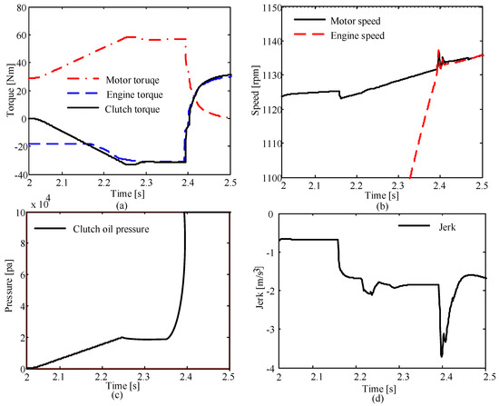
Figure 12.
The simulation results for the motor-assisted engine starting process. (a) The changing curves of torque; (b) the changing curves of speed; (c) the clutch oil pressure curve; and (d) the jerk during mode switch.
As shown in Figure 12, at the beginning, the vehicle operates in Ev-mode. At 2 s, the vehicle controller sends out switching instructions. From the clutch oil pressure curve, it can be seen that the oil pressure begins to rise. From the changing curves of torque, it can be seen that the motor torque compensates the wet clutch torque. At 2.16 s, the wet clutch torque is greater than the engine dragging torque, and the engine starts to rotate. At 2.37 s, the engine speed is equal to the motor speed, and the torque transmitted by the clutch and the engine dragging torque are equal. At this time, the engine ignites, and the motor offsets the torque fluctuation when the engine starts. As shown in the changing curves of torque, the system output torque fluctuation is small, and the system’s speed fluctuation is also small as shown in the speed curve. The jerk curve shows that the maximum jerk during this mode switch is −3.9 m/s3. In China, the recommended value of vehicle’s jerk is [31]. Therefore, this mode switch fully meets the requirements of China.
The simulation results of the mode switch from Eng-mode to EV-mode are shown in Figure 13. The vehicle drives in Eng-mode. As the total driving torque decreases, the vehicle controller sends mode switching instructions at 2.1 s. The engine begins to decrease the engine torque, and the motor increases its torque to compensate for the difference between the required torque and engine torque. At 2.22 s, the absolute value of the difference between the motor torque and the motor target torque is within the allowable range, and the engine shuts down. At the same time, the clutch begins to separate quickly, and the motor compensates the resistance torque produced when the clutch is not completely separated; at 2.23 s, the mode switch ends, and the vehicle is only driven by the motor. As shown in the jerk curve, the maximum jerk during this mode switch is 0.97 m/s3, which means that the vehicle ride comfort is good during this mode switching.
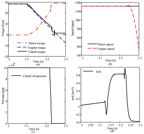
Figure 13.
The simulation results for the mode switch from Eng-mode to EV-mode. (a) The changing curves of torque; (b) the changing curves of speed; (c) the clutch oil pressure curve; and (d) the jerk during mode switch.
5.2. Bench Test Analysis
The plug-in hybrid system’s test bench, shown in Figure 14, was built up. This bench system consisted of an engine, an ISG motor, a lithium iron phosphate battery, a CVT, a braking system, a loading system, and a control system. The power source included a gasoline engine (the peak power was 90 kW and the maximum torque was 155 Nm), an ISG motor (the peak power was 30 kW and the maximum torque was 113 Nm), and a lithium iron phosphate battery pack (the capacity was 30 Ah and the rated voltage was 316 V). The control software was developed using MATLAB/Simulink (MathWorks, Natick, MA, USA), and the D2P (From Development to Production) was used as the controller of this test system.
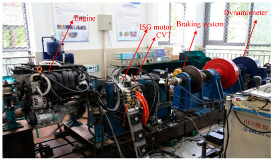
Figure 14.
The hybrid system’s test bench.
As is well known, the motor-assisted engine starting process is the most important and complicated mode switching in the hybrid system. Therefore, the combined control strategy for motor-assisted engine starting was conducted on the test bench. The results are shown in Figure 15. As shown, the vehicle runs in Ev-mode at the beginning. At 132.8 s, the working mode of the vehicle is transferred from Ev-mode to Hev-mode. The wet clutch begins to engage and the motor torque increases. At 133.1 s, when the engine speed is close to the motor speed, the engine is ignited. The motor compensates the engine’s torque ripple. Since the output torque of the ignition engine is not stable, the motor compensates the torque ripple. When the absolute value of the difference between the engine torque and the engine target torque is within the allowable range, the wet clutch engages quickly. Finally, the vehicle operates in Hev-mode. According to Figure 15d, the maximum jerk of the vehicle is about 9.32 m/s3, which is a reasonable jerk. Therefore, the experiment results indicated that the control strategy for motor-assisted engine starting was effective.
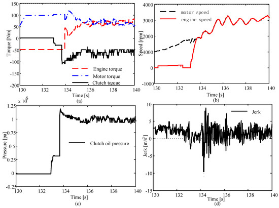
Figure 15.
The experiment results. (a) The changing curves of torque; (b) the changing curves of speed; (c) the clutch oil pressure curve; and (d) the jerk during mode switch.
6. Conclusions
This paper focused on a control strategy for driving mode switches of plug-in hybrid electric vehicles with a multi-disk wet clutch. The dynamic model of the PHEV was established, and a rule-based control strategy was proposed to divide the working mode regions and distribute the torque between engine and motor. Then, the dual fuzzy control strategy for a wet clutch and the coordinated torque control strategy for driving mode switches were proposed. The dual fuzzy logic control system consisted of the initial PWM’s duty cycle control and the changing rate of the PWM’s duty cycle control.
To verify the effectiveness of the proposed control strategy, simulations of driving mode switches between Ev-mode and Eng-mode were conducted. The results showed that the proposed control strategy could reduce the torque ripple and the jerk of the vehicle, completely satisfying the requirements of China. Furthermore, the combined control strategy for the motor-assisted engine starting process was tested on the bench. The experiment results indicated that the proposed strategy was effective.
In this paper, the authors did not study a control strategy for the braking mode switching and the mode switching between braking mode and driving mode. However, the coordinated control strategy for the driving mode switch proposed in this paper can provide reference for a control strategy for these two types of mode switches.
Author Contributions
Y.Z. wrote the paper and provided algorithms; Y.C. built the simulation model and completed the simulation; Y.X. analyzed the simulation results; Y.L. and Y.S. completed the bench test and analyzed the experiment results; Z.H. provided suggestions for the manuscript.
Funding
This research was funded by the National Natural Science Foundation of China (Grant No. 51665020 and 61472173) and the State Key Laboratory of Mechanical Transmission’s open fund (Grant No. SKLMT-KFKT-201617).
Conflicts of Interest
The authors declare no conflict of interest.
Nomenclature
| CVT | Continuously variable transmission |
| Char-mode | Charging mode during driving |
| The PWM’s duty cycle | |
| The initial PWM’s duty cycle | |
| The changing rate of PWM’s duty cycle | |
| The output force of the plunger | |
| EPV | Electric-hydraulic proportional valve |
| Ev-mode | Pure electric driving mode |
| Eng-mode | Only engine driving mode |
| Hev-mode | Hybrid driving mode |
| ISG | Integrated starter and generator |
| The changing rate of the engine torque | |
| MPC | Model predictive controller |
| The motor’s speed | |
| The engine launch speed limit | |
| PHEV | Plug-in hybrid electric vehicle |
| PWM | Pulse-width modulation |
| The clutch pressure | |
| SOC | The state of charge |
| The lower limit of discharge | |
| The required torque | |
| The engine’s output torque | |
| The motor’s output torque | |
| The maximum torque of the engine | |
| The maximum torque of the motor | |
| The clutch torque | |
| The engine dragging torque | |
| The accelerator pedal’s opening | |
| The change rate of the accelerator pedal’s opening | |
| The difference in the clutch plate’s speed |
References
- Iodice, P.; Senatore, A. Exhaust emissions of new high-performance motorcycles in hot and cold conditions. Int. J. Environ. Sci. Technol. 2015, 12, 3133–3144. [Google Scholar] [CrossRef]
- Iodice, P.; Senatore, A. Road transport emission inventory in a regional area by using experimental two-wheelers emission factors. In Proceedings of the World Congress on Engineering, London, UK, 3–5 July 2013. [Google Scholar]
- Hu, X.; Martinez, C.M.; Yang, Y. Charging, power management, and battery degradation mitigation in plug-in hybrid electric vehicles: A unified cost-optimal approach. Mech. Syst. Signal Proc. 2017, 87, 4–16. [Google Scholar] [CrossRef]
- Hu, X.; Moura, S.J.; Murgovski, N.; Bo, E.; Cao, D. Integrated Optimization of Battery Sizing, Charging, and Power Management in Plug-In Hybrid Electric Vehicles. IEEE Trans. Control Syst. Technol. 2016, 24, 1036–1043. [Google Scholar] [CrossRef]
- Zeng, Y.; Cai, Y.; Chu, C.; Kou, G.; Gao, W. Integrated Energy and Catalyst Thermal Management for Plug-in Hybrid Electric Vehicles. Energies 2018, 11, 1761. [Google Scholar] [CrossRef]
- Gao, H.; Cheng, B.; Wang, J.; Li, K.; Zhao, J.; Li, D. Object classification using CNN-based fusion of vision and LIDAR in autonomous vehicle environment. IEEE Trans. Ind. Inform. 2018, 14, 4224–4231. [Google Scholar] [CrossRef]
- Xie, G.; Gao, H.; Qian, L.; Huang, B.; Li, K.; Wang, J. Vehicle trajectory prediction by integrating physics- and maneuver-based approaches using interactive multiple models. IEEE Trans. Ind. Electron. 2018, 65, 5999–6008. [Google Scholar] [CrossRef]
- Li, D.; Gao, H. A hardware platform framework for an intelligent vehicle based on a driving brain. Engineering 2018, 4, 464–470. [Google Scholar] [CrossRef]
- Hu, X.; Wang, H.; Tang, X. Cyber-physical control for energy-saving vehicle following with connectivity. IEEE Trans. Ind. Electron. 2017, 64, 8578–8587. [Google Scholar] [CrossRef]
- Chen, L.; Xi, G.; Sun, J. Torque coordination control during mode transition for a series–parallel hybrid electric vehicle. IEEE Trans. Veh. Technol. 2012, 61, 2936–2949. [Google Scholar] [CrossRef]
- Lin, Y.; Qin, D.; Liu, Y.; Yang, Y. Control strategy for all the mode-switches of hybrid electric vehicle. Adv. Mech. Eng. 2016, 8, 1–17. [Google Scholar] [CrossRef]
- Chen, L.; Xi, G. Torque coordination of clutch, engine and motor during power transition for a hybrid electric bus. In Proceedings of the 2010 IEEE Vehicle Power and Propulsion Conference, Lille, France, 1–3 September 2010. [Google Scholar]
- Tong, Y.; Lu, X.; Yang, M. Model simplification and sliding mode control of automotive powertrain. In Proceedings of the SAE 2002 World Congress, Detroit, MI, USA, 18–20 November 2002. [Google Scholar]
- Tong, Y.; Li, J.; Zhang, J.; Yang, F.; Zhang, K.; Yang, M.G. Coordinating control oriented research on algorithm of engine torque estimation for parallel hybrid electric powertrain system. In Proceedings of the SAE 2004 World Congress & Exhibition, Detroit, MI, USA, 8–11 March 2004. [Google Scholar]
- Mansour, C.; Clodic, D. Modeling of the THS-II series/parallel powertrain and its energy management system. In Proceedings of the FISITA 2010 World Automotive Congress, Budapest, Hungary, 30 May–4 June 2010. [Google Scholar]
- Meisel, J. Kinematic study of the GM Front-Wheel drive two-mode transmission and the Toyota hybrid system THS-II transmission. SAE Int. J. Engines 2011, 4, 1020–1034. [Google Scholar] [CrossRef]
- Yang, C.; Jiao, X.; Li, L.; Zhang, Y. Robust coordinated control for hybrid electric bus with single-shaft parallel hybrid powertrain. IET Control Theory Appl. 2015, 9, 270–282. [Google Scholar] [CrossRef]
- Yang, C.; Jiao, X.H.; Li, L. Electromechanical coupling driving control for single-shaft parallel hybrid powertrain. Sci. China Technol. Sci. 2014, 57, 541–549. [Google Scholar] [CrossRef]
- Su, Y.; Hu, M.; Su, L.; Qin, D.; Zhang, T.; Fu, C. Dynamic coordinated control during mode transition process for a compound power-split hybrid electric vehicle. Mech. Syst. Signal Proc. 2018, 107, 221–240. [Google Scholar] [CrossRef]
- Minh, V.T.; Rashid, A.A. Modeling and model predictive control for hybrid electric vehicles. Int. J. Automot. Technol. 2012, 13, 477–485. [Google Scholar] [CrossRef]
- Beck, R.; Richert, F.; Bollig, A.; Abel, D. Model predictive control of a parallel hybrid vehicle drivetrain. In Proceedings of the 44th IEEE Conference on Decision and Control, Seville, Spain, 15 December 2005. [Google Scholar]
- Sun, J.; Xing, G.; Liu, X.; Fu, X.; Zhang, C. A novel torque coordination control strategy of a single-shaft parallel hybrid electric vehicle based on model predictive control. Math. Probl. Eng. 2015, 2015, 960678. [Google Scholar] [CrossRef]
- Wang, S.; Xia, B.; He, C.; Zhang, S.; Shi, D. Mode transition control for single-shaft parallel hybrid electric vehicle using model predictive control approach. Adv. Mech. Eng. 2018, 10. [Google Scholar] [CrossRef]
- Yang, Y.; Wang, C.; Zhang, Q.; He, X. Torque coordination control during braking mode switch for a plug-in hybrid electric vehicle. Energies 2017, 10, 1684. [Google Scholar] [CrossRef]
- Zhao, Z.; He, N.; Zhu, Y.; Yu, Z. Mode transition control for four wheel drive hybrid electric car. J. Mech. Eng. 2011, 47, 100–109. [Google Scholar] [CrossRef]
- Ma, S.; Yuan, H.; Song, J.; Wang, J. On-line energy distribution for hybrid electric vehicles using optimal power-split-ratio. In Proceedings of the 2014 33rd Chinese Control Conference, Nanjing, China, 28–30 July 2014. [Google Scholar]
- Liu, Y.; Chen, Q.; Lei, Z.; Qin, D.; Zhang, Y.; Wu, R. Modeling and control of engine starting for a full hybrid electric vehicle based on system dynamic characteristics. Int. J. Automot. Technol. 2017, 18, 911–922. [Google Scholar] [CrossRef]
- Lei, Z.; Sun, D.; Liu, Y.; Qin, D.; Zhang, Y.; Chen, L. Analysis and coordinated control of mode transition and shifting for a full hybrid electric vehicle based on dual clutch transmissions. Mech. Mach. Theory 2017, 114, 125–140. [Google Scholar] [CrossRef]
- Gong, W.; Liu, X.; Sun, Y. Method of electronic-hydraulic proportion control. J. Jilin Univ. Technol. 2003, 33, 104–107. [Google Scholar]
- Renn, J.; Tsai, C. Development of an unconventional electro-hydraulic proportional valve with fuzzy-logic controller for hydraulic presses. Int. J. Adv. Manuf. Technol. 2005, 26, 10–16. [Google Scholar] [CrossRef]
- Gu, Y.; Yin, C.; Zhang, J. Investigation to coordinated torque control strategy of parallel hybrid electric vehicles. J. Syst. Simul. 2007, 19, 170–175. [Google Scholar]


© 2018 by the authors. Licensee MDPI, Basel, Switzerland. This article is an open access article distributed under the terms and conditions of the Creative Commons Attribution (CC BY) license (http://creativecommons.org/licenses/by/4.0/).