1. Introduction
The generator will play a more and more important role in the more electric sustainable mobility, such as aircrafts, extended range EV and hybrid EV power generation. However, because of the poor working conditions, high failure rate and short life, the generator should increase the reliability and availability continuously. For these important transportation applications, generators should have the ability to continue performing their intended functions even under phase fault [
1,
2]. Multiphase machines with more than three phases can be applied because they can continue to run even with one or two open-circuited phases [
3]. Hence, itis necessary to design multi-phase generators with the capability of fault tolerance.
To improve the reliability of the system, various machines and converters have been studied. However, these studies mainly concentrate on permanent magnet synchronous machines [
3], induction machines [
4], and their converters [
5,
6,
7]. Many of them proposed a good fault-tolerant performance of the multi-phase machine. Because of the advantages of brushless, high robustness, and high reliability, the switched reluctance generator (SRG) and the doubly salient permanent magnet generator (DSPMG) were proposed in Reference [
8]. However, as a generator, SRG usually requires shaft position sensors, and suffers from the problem of excitation and low efficiency at low speed. In addition, the DSPMG has the drawbacks of high permanent material cost and uncontrollable flux, particularly in the case of faults.
Hybrid excitation machines with a PM generator and field windings were proposed to provide controlled flux [
9]. However, they also have the risk of PM demagnetization because of the big field current and high temperature. What is more, the complicated structure of hybrid excitation machines brings high cost and complicated manufacturing process.
The Brushless Doubly-Fed SR Machine (BDFSRM) was studied in Reference [
10]. This type of machine has two sets of stator windings, but its stator poles are not salient ones. The BDFSRM needs the space vector theory and d–q model to control the machine torque/voltage.
The doubly Salient Electro-magnetic generator (DSEG) is a new generator developed from switched reluctance generator [
11]. It keeps the main merits both with a wound-field synchronous generator and switched reluctance generator, such as low cost, simplicity and reliability. In addition, the output voltage of DSEG is controlled by the DC exciting current easily [
12]. The DSEG with the rectifier may provide constant DC output voltage by regulating the field winding current. Hence, the voltage regulation and efficiency optimization can be easily realized.
The traditional three-phase DSEG shown in Reference [
13] has three-phase star windings, which are connected to a three-phase full-bridge rectifier. When there is a fault in the windings or rectifier, the generator will not work normally because the normal phase cannot form a circuit loop with the fault phase. To provide the ability of isolation, a three-phase H bridge rectifier was adopted in Reference [
14] and a double channel DSEG is developed with double three-phase winding in one stator [
15]. Compared with the above multi-channel DSEG, the multiphase DSEG with more than three phases is advantageous for fault-tolerant operation, because it has a redundant phase to provide the fault-tolerant ability.
In the next-generation transportation system, the feature of electrification, strong connection, automation, and fault-tolerant technologies will benefit a lot to improve the future vehicles [
16,
17,
18,
19]. To further improve the reliability of the generation system, the multiphase machines can be applied because they can continue to run even with one or two open-circuited phases [
20,
21,
22]. Although the 8/6-pole four-phase fault-tolerant doubly salient PM machine had been designed to offer fault-tolerance with a high torque [
23], it is very difficult to make it as a fault tolerant generator because its flux cannot be well controlled. If we replace its PM steel with wound-field windings to make an 8/6-pole four-phase DSEG, the DSEG will have a shortcoming of asymmetric phases. As the fault tolerant machine should have the characteristic of isolation and redundancy [
24]. If the four-phase windings of the DSEG are isolated from each other, the current of different phases will not equal if its max inductance is not equal, which will bring torque ripples and asymmetric phase load. Therefore, the asymmetry of the multi-phase fault-tolerant DSEG is very necessary to study.
The phase asymmetry of traditional three-phase DSEG was not well valued because its asymmetric degree is not very high. In References [
25,
26], a three-phase doubly salient permanent magnet motor was designed, and the 24/28-pole outer rotor structure is used to reduce the torque ripple. The paper intimates that the doubly salient machine can be designed symmetrically if the rotor and stator poles are well designed.
If we want to keep the operating of the DSEG with one or two open-circuited phases, the best choice is to design multiphase machines with more than three phases. However, the multiphase DSEG has the drawback of phase asymmetry, and the asymmetry grows up with the phase number of the DSEG.
Therefore, in this paper, the mathematical model of the machine and fault-tolerant rectifiers should be proposed first, which indicates that the four-phase fault-tolerant DSEG should have symmetric phases. The traditional three-phase DSEG is usually connected with a three-phase full bridge rectifier, but it has no ability of fault-tolerance. Therefore, several generating modes with phase-isolated rectifiers will be proposed and compared with their fault-tolerant performance in this paper next. Finally, a new 12/9-pole DSEG with symmetric phases will be proposed and different generating modes with four-phase full bridge rectifier, positive half-wave rectifier and four-phase H bridge rectifier will be presented. The voltage waveforms, no-load characteristics and loading characteristics with different rectifiers will be given based on the simulation and the experiment on a prototype of DSEG.
3. The Four-Phase DSEG with Symmetrical Phases
3.1. Asymmetry Analysis of Traditional DSEG
The traditional 8/6-pole four-phase DSEG is raised from a 6/4-pole three-phase doubly salient machine. However, it has the drawback of unbalanced phases. To introduce this unbalance phenomenon, the magnetic paths of traditional 8/6-pole four-phase DSEG are shown in
Figure 1. F
f and F
p are the magnetic potential of the field winding and the p-phase armature windings; R
sy, R
sp, R
ry and R
rp are the reluctance of stator yoke, stator pole, rotor yoke and rotor pole, respectively. R
g and R
s1 are the air gap reluctance and stator leakage reluctance, respectively. G is the length of the air gap. If the magnetic field intensity H, magnetic flux density B, length of magnetic path l and cross-sectional area S are described with the same subscript as the reluctance R respectively, R
sy, R
sp, R
ry, R
rp and R
g can be written as
where
is the permeability of vacuum,
Sg is the sectional area of the air gap.
For this 8/6-pole DSEG, the two field windings are wound across four poles and four armature windings and it will provide two excitation sources for Ff. The coil of A-phase and D-phase is nearby Ff, and the coil of B-phase and C-phase is a little far away from Ff.
When the rotor pole is right in line with the stator pole of A-phase, the magnetic path of A-phase is distinguished with a bold red line in (a), and when the rotor pole is in line with the stator pole of B-phase, the magnetic path of B-phase in (b) is much longer than A-phase. Similarly, the magnetic path of C-phase is much longer than D-phase.
Ignoring the leakage magnetic, the maximum flux of A-phase can be achieved in
Figure 1c. The magnetic potential of the field winding F
f at this moment can be described as:
where
Nf and i
f are the turns and current of field winding.
is the magnetic flux of A-phase.
The maximum flux of B-phase can be achieved in
Figure 1d. At this moment, the magnetic potential of the field winding F
f can be described as:
Compare (3) with (4), the total reluctance of A-phase and B-phase is not equal, and the total reluctance of C-phase and D-phase is not equal too. Since the long magnetic path means the big magnetic reluctance, the magnetic reluctance of B-phase is larger than A-phase, and the inductance between field winding and phase winding of the A-phase is larger than B-phase. This is why there is an asymmetry among the phases of traditional 8/6-pole DSEG.
3.2. Symmetry Analysis of New DSEG
In order to solve the above problems of traditional DSEG, this paper proposes a new field winding and phase winding configuration.
Let j be the pole numbers that a field coil curl around. When j = 1, which means a stator pole has a field coil and a phase coil, the DSEG will be a variable flux reluctance doubly salient machine [
13]. When j = 2, a field winding coil provides the magnetic field for two phase windings. The copper consumption of the field winding will be increased because they need six field winding coils. While j = 4, the machine will be a traditional DSEG [
24], and it has the problem of asymmetric phases. As shown in
Table 1. If j is larger than 4, the field windings should cross a large number of stator poles, and the flux leakage will increase. Therefore, for the four-phase DSEG, the preferred values of j is equal to 3.
As the rotor pole number
pr can be calculated with
where
m is the phase number and
ps is the stator pole number. When
m = 4, the elementary machine of four-phase DSEG with symmetric phases has 12 stator poles and 9 or 15 rotor poles, which are called12/9-pole machine or 12/15-pole machine. For the reluctance machine, the number of rotor poles is better to be a little number.
In this paper, a 12/9-pole four-phase DSEG is given, whose stator pole arc and rotor pole arc are expressed as
3.3. New DSEG with Symmetrical Phases
The proposed 12/9-pole DSEG is shown in
Figure 2a. A1, B2 and F3 respectively represent the first coil of A-phase, the second coil of B-phase, and the third coil of field windings. There are three phase coils which are series connected in a phase winding. The magnetic paths of the A2 and A3 are short, and the magnetic path of A1 is long, as shown in
Figure 2b.
The maximum flux of A-phase can be achieved in
Figure 2. At this moment, there are three coils with deferent magnetic roads. The magnetic potential of coil A1 and A3 can be described as:
And the magnetic potential of coil A2 can be described as:
In the other three phases, there are two short magnetic paths and one long magnetic path too.
Figure 2c gives the inductance vector of the 12/9-pole DSEG. In the new 12/9-pole DSEG, each phase winding has a coil with little inductance and two coils with large inductance, and when the three coils are series connected, the total inductance of each phase winding is equal. The symmetry of the four-phase inductance is achieved.
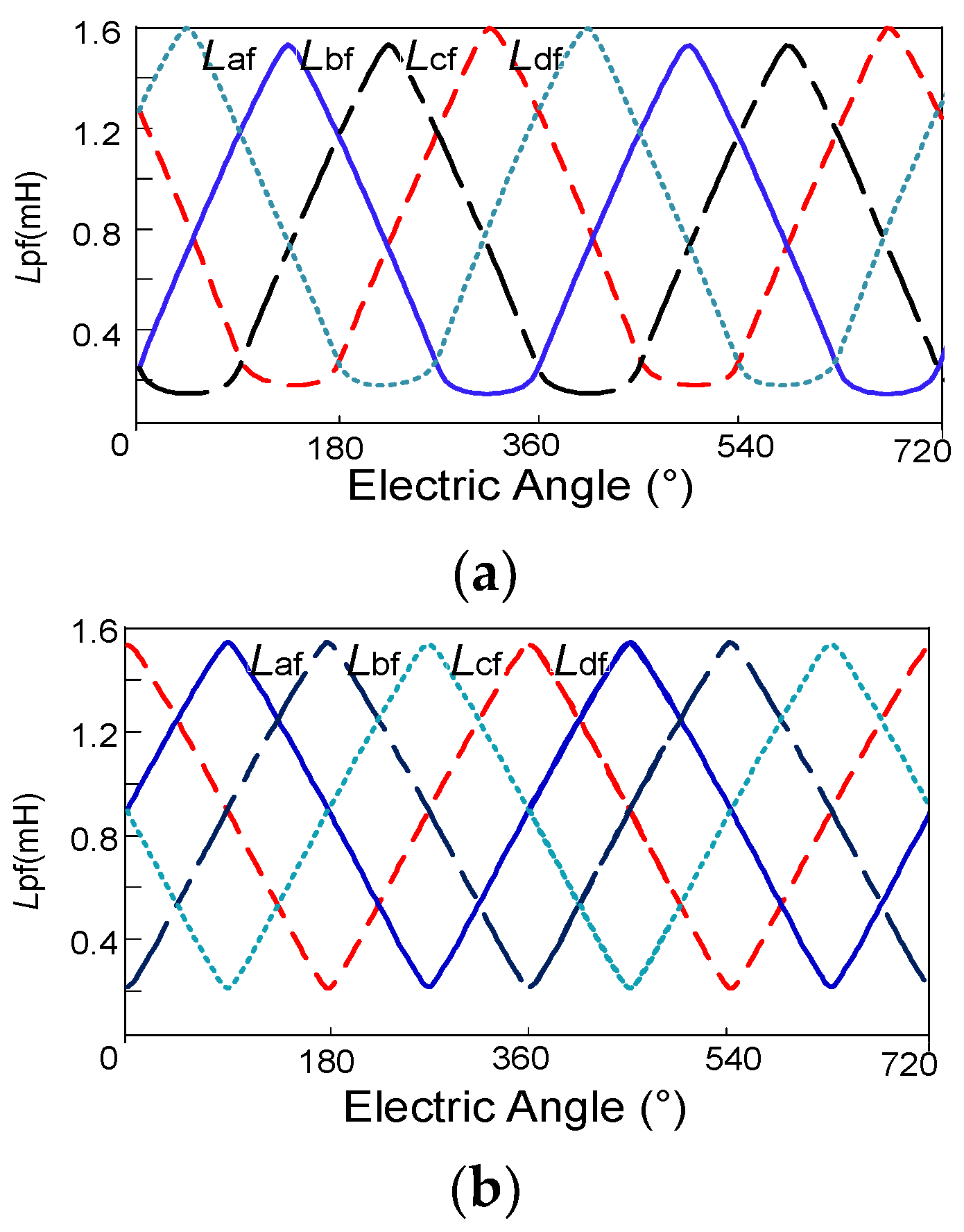
To verify the above analysis of the traditional and new four-phase DSEG, the simulation inductance of
Lpf is shown in
Figure 3a,b. The electrical angle when
Lpf is increasing or decreasing is 135°. If we define the electrical angle when
Lpf is increasing as EMF electrical angle. That is to say, the EMF electrical angle of traditional four-phase DSEG is 135°. While in the new 12/9-pole DSEG, the electrical angle of EMF waveform is 180°. At any time, the four-phase inductors are changing at the same speed. Each phase can output voltage at any time.
The inductances between different phase windings
Lab,
Lac,
Lad are shown in
Figure 3c with the parameters shown in Reference [
7]. It can be seen that
Lpf is hundreds of times of
Lab,
Lac and
Lad. So the coupling between phases can be ignored, and the machine has good ability for phase isolation.
It should be noted that the four-phase DSEG with nine rotor poles has an unbalanced magnetic force on the rotor. As the 9/8-pole BLDC, although they have an unbalanced magnetic force, they are elementary machines, and their unbalanced magnetic forces can be eliminated by employing two elementary machines.
4. The Four-Phase DSEG and Its Rectifiers
A prototype was developed to verify the fault-tolerant characteristics of the new 12/9 pole four-phase DSEG. Its main structural parameters are shown in
Table 2. The machine shell is from a traditional alternator of a truck. The pole numbers and pole arc coefficient are designed according to the topology criteria of the multiphase DSEG proposed in Reference [
7], and the turn numbers of the windings are designed according to the design manual for the electric machine.
The stator and rotor photographs are shown in
Figure 4a.
DSEG has several generating modes with the different rectifiers. In order to ensure the work of the other redundant phase or channel, the fault tolerant motors should be able to isolate the failure phase or failure channel, and keep it out of the normal ones. The rectifiers with the ability of isolation and fault-tolerance are shown in
Figure 4.
The first one is a four-phase full bridge rectifier, which can be divided into two channels by disconnecting the neutral point, as shown in
Figure 4b. This is the difference from a common full bridge rectifier.
Figure 4c is the positive half-wave rectifier. It is very similar to the negative half-wave rectifier. Both of the half-wave rectifiers have the ability for fault isolation. With the positive half-wave rectifier, the generator can output voltage when the rotor poles are sliding out the stator poles and the negative half-wave rectifier works only when the rotor poles are sliding in the stator poles. With a negative half-wave rectifier, the armature reaction demagnetizes the excitation field and reduces the output power. This paper will discard the negative half-wave rectifier and only discuss the positive half-wave rectifier, which is also called an SRM rectifier [
15]. The last one is four-phase H bridge rectifier, which connected each phase winding with an H bridge. All the four-phase windings are isolated from each other, as shown in
Figure 4d.
All of the fault-tolerant rectifiers have redundant channels, and if the max voltages of different channels are not equal, the loads of different channels will not equal too.
Unfortunately, for the traditional DSEG, the max values of Lpf are not equal, because the positions between phase windings and field windings are different. So it is very necessary to develop a DSEG with symmetrical phases.
For this new type of generator, the output voltage
uo changes with its rectifier. For the four-phase full bridge rectifier,
uo can be expressed as
where
uac and
ubd are the line voltage of A-phase to C-phase and B-phase to D-phase.
For example, when the rotor pole is approaching the stator pole of A-phase,
uac is larger than the load voltage. The dynamic equation can be written as
For the positive half-wave rectifier,
where
up is the phase voltage and the subscript p represents phase A, B, C or D.
When the rotor pole is approaching the stator pole of A-phase,
ua is larger than the load voltage. The dynamic equation can be written as
For the four-phase H bridge rectifier,
When the rotor pole is approaching the stator pole of A-phase,
is larger than the load voltage. The dynamic equation can be written as
The fault of the phase winding and the rectifier can be divided into short-circuit fault and open-circuit fault [
21]. The short-circuit fault of the rectifier may cause the electric source or phase winding short-circuit, which will bring a huge short-circuit current and is very dangerous to the whole system. Because the short-circuit fault is contagious, it is very necessary to isolate it and treat it as an open-circuit fault. Therefore, this paper only analyzes open-circuit fault.
The four-phase full bridge rectifier, positive half-wave rectifier and four-phase H bridge rectifier were built in an experiment bed. The characteristics experiment of normal state and fault state were done to get the voltage wave, no-load characteristics and external characteristics
Figure 5a shows the normal voltage waveform of the generator with a four-phase full bridge rectifier. As the electrical angle between A-phase and C-phase is 180°, and they can be connected oppositely in the first channel. The second channel is made up of B-phase and D-phase, which are 90° to A-phase and C-phase. After being rectified, the stable DC voltage can be obtained. The normal output voltage waveform with the positive half-wave rectifier and the four-phase H bridge rectifier is similar to
Figure 5a.
As a typical fault, the one phase open-circuit fault will be studied to test the fault tolerant performance of the three rectifiers.
Figure 5b–d shows the voltage waveforms of the four-phase full bridge rectifier, positive half-wave rectifier and four-phase H bridge rectifier with one phase open-circuit fault. Limited to the length of this paper, we will not give the voltage waveforms of other faults.
To evaluate the voltage ripple and the harmonics, the equations for calculating the voltage ripple
Kv and the total harmonic distortion (THD) are shown in (14) and (15), in which
Vi and
V1 are the root mean square (RMS), value of the ith harmonic and the amplitude of the fundamental component.
The voltage ripple
Kv and THD with different rectifiers are calculated and compared in
Table 3. As can be seen from the Table, the four-phase full bridge rectifier cannot be used to tolerate the fault of the adjacent two phases open-circuit. The positive half-wave rectifier can tolerate the fault of one diode open-circuit, one phase open-circuit and adjacent two phases open-circuit. Meanwhile, the voltage ripple
Kv and THD of the four-phase full bridge rectifier and the positive half-wave rectifier are very high because their redundant phases that can be used are less than the four-phase H bridge rectifier. As a rectifier with four channels of isolated phases, the voltage ripple
Kv and THD of four-phase H bridge rectifier are low, and the rectifier has a good performance with open-circuit fault. So it is an ideal fault-tolerant rectifier except for the fact that its cost is high.
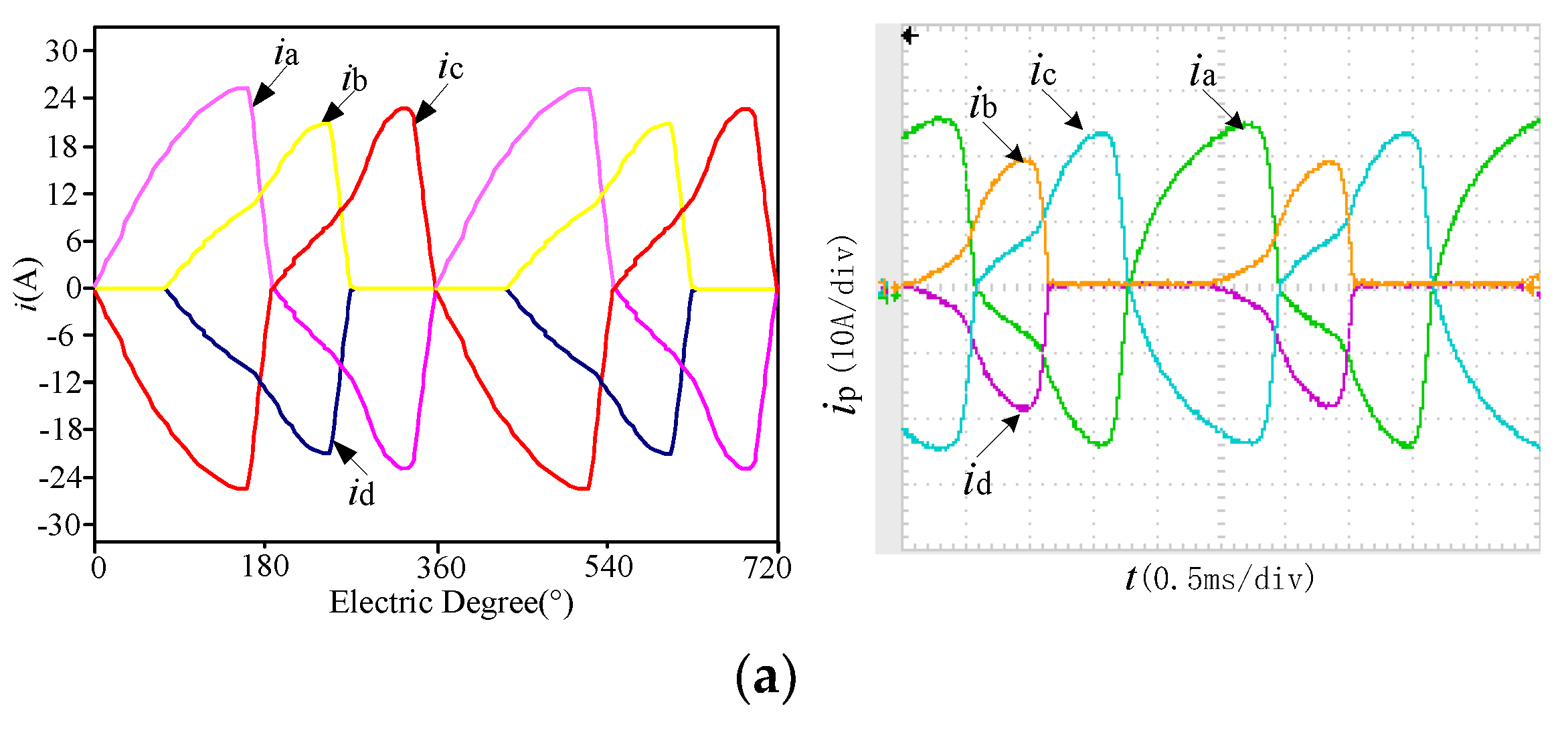
6. External Characteristic
Figure 7 shows the waveforms of different rectifiers with 5 A field current and 1 Ω load, at the speed of 2667 r/min to show just two periods waveforms. Due to the armature reaction of the phase windings, the waveforms of the phase current are distorted. Although the four-phase DSEG no-load electromotive force waveform has an electrical angle of 180°, the electrical angle of the four-phase current waveforms is less than 180°, because the armature reaction delayed the inflection point of the flux linkage from rising to falling. This flux-enhancing and weakening phenomenon is especially clear in
Figure 7c.
To verify the machine’s fault-tolerant performance of different phases, the phase current waveforms of the DSEG in the two fault conditions of one diode open-circuit and one phase open-circuit is shown in
Figure 8 at the speed of 2667 r/min, since the oscilloscope can display just two complete waveforms at this speed [
27]. When there is no fault, the current amplitudes of different phases are equal.
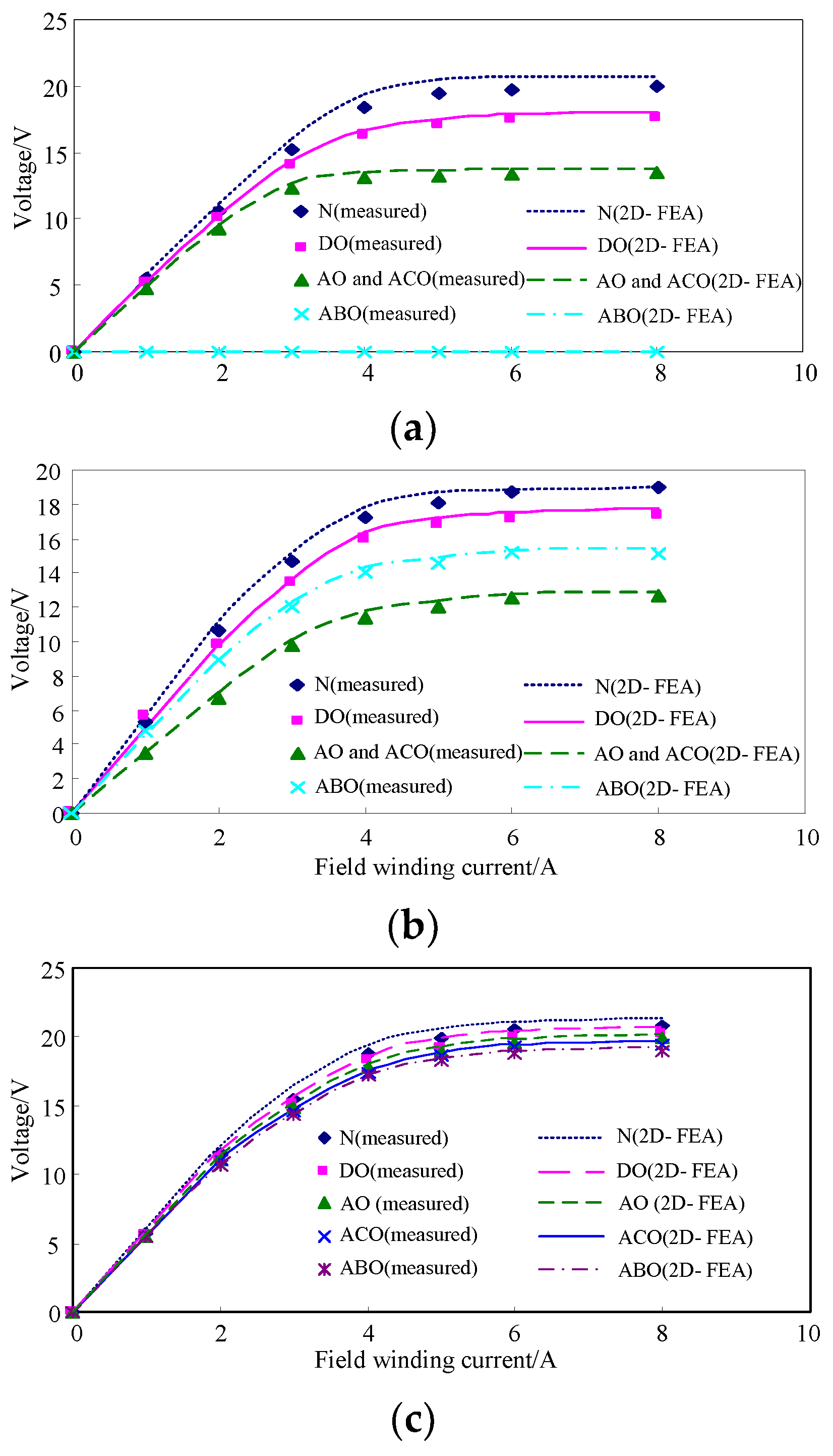
When the generator is loaded with a resistor, the machine’s fault tolerant capabilities can be directly reflected by its external characteristic. With the external characteristic plotted in
Figure 9a, we can see that the generator with the four-phase full bridge rectifier can tolerate the one diode open-circuit fault, one-phase open-circuit fault and adjacent two phases open-circuit fault. For example, when D1 in
Figure 4b is open, D2 can still rectify the negative half-wave of the A-phase and C-phase. Therefore, the output voltage of one diode open-circuit is higher than one-phase open-circuit.
Figure 9b shows the external characteristic with a positive half-wave rectifier. As can be seen from the figure, the generator can tolerate the fault of one diode open, one phase open-circuit and two phases open-circuit. When there is a two-phase open-circuit fault, the rest of the two phases can remain working. In addition, the fault performance of the opposite two phases open-circuit is better than the adjacent two phases open-circuit.
Based on the external characteristic with four-phase H bridge rectifier shown in
Figure 9c, it can be seen that when there is an open-circuit fault of one diode, one phase and two phases, the machine still has a high performance. Because the adjacent two-phase open-circuit fault has a good complementary of phase voltage waveform, its voltage is larger than the fault of the opposite two phases open-circuit.
From
Figure 9, we can see that the DSEG with four-phase H bridge rectifier has the best performance of fault tolerant, and
Figure 9 shows the same conclusion as
Figure 6.
7. Conclusions
The generator with redundant phases or redundant channels is very suitable to build a fault-tolerant generator system. To make the different channels or phases have an equal load, the machine should have symmetrical phases with the same amplitude of phase voltage and inductance.
A new 12/9-pole four-phase DSEG with symmetrical phases is proposed in this paper. Each phase winding of the machine consists of three concentrated coils, although the inductance of one coil is lower than the others, each phase has only one coil with lower inductance. So the phase windings which are composed of three coils have the same amplitude of phase voltage and inductance.
The four-phase DSEG can be equipped with a four-phase full bridge rectifier, four-phase half-wave rectifier and four-phase H bridge rectifier. The four-phase H-bridge rectifier can tolerate the fault of one diode open, one phase open-circuit and two phases open-circuit with a low voltage ripple and low THD. It has the best fault tolerant no-load characteristic and external characteristic, except that it needs more diodes.


