Article

An Adaptable Engineering Support Framework for Multi-Functional Energy Storage System Applications

by
Claudia Zanabria
1,*,
Filip Pröstl Andrén
1 and
Thomas I. Strasser
1,2
1
Center for Energy—Electric Energy Systems, AIT Austrian Institute of Technology, 1210 Vienna, Austria
2
Institute of Mechanics and Mechatronics, Vienna University of Technology, 1040 Vienna, Austria
*
Author to whom correspondence should be addressed.
Sustainability 2018, 10(11), 4164; https://doi.org/10.3390/su10114164
Submission received: 17 September 2018 / Revised: 23 October 2018 / Accepted: 31 October 2018 / Published: 12 November 2018
(This article belongs to the Special Issue Smart Energy Management for Smart Grids)

Abstract

:
A significant integration of energy storage systems is taking place to offer flexibility to electrical networks and to mitigate side effects of a high penetration of distributed energy resources. To accommodate this, new processes are needed for the design, implementation, and proof-of-concept of emerging storage systems services, such as voltage and frequency regulation, and reduction of energy costs, among others. Nowadays, modern approaches are getting popular to support engineers during the design and development process of such multi-functional energy storage systems. Nevertheless, these approaches still lack flexibility needed to accommodate changing practices and requirements from control engineers and along the development process. With that in mind, this paper shows how a modern development approach for rapid prototyping of multi-functional battery energy storage system applications can be extended to provide this needed flexibility. For this, an expert user is introduced, which has the sole purpose of adapting the existing engineering approach to fulfill any new requirements from the control engineers. To achieve this, the expert user combines concepts from model-driven engineering and ontologies to reach an adaptable engineering support framework. As a result, new engineering requirements, such as new information sources and target platforms, can be automatically included into the engineering approach by the expert user, providing the control engineer with further support during the development process. The usefulness of the proposed solution is shown with a selected use case related to the implementation of an application for a battery energy storage system. It demonstrates how the expert user can fully adapt an existing engineering approach to the control engineer’s needs and thus increase the effectiveness of the whole engineering process.

1. Introduction

The reduction of CO 2 emissions is motivating the integration of renewables into power grids. As a consequence, a higher penetration of distributed generators such as Photovoltaic (PV), wind turbines, and small hydro power stations is taking place [1]. A side effect of this is the perturbation of the power system stability and quality. Those issues were addressed by different studies [2], which encourage the use of Battery Energy Storage Systems (BESS). Moreover, BESS can also support services related to the minimization of supply costs and market integration, among others [3]. Consequently, BESS will play a multi-functional role in the near future. The BESS is often accompanied by an Energy Management Systems (EMS) where the BESS’s services and functions are hosted. Hence, the EMS should exchange information with stakeholders and Intelligent Electronic Devices (IEDs) spread out over the electric grid. Thereby, the EMS development process should consider interoperability across systems as well as evolving requirements of smart grid systems. In this context, the realization of EMS involves challenging tasks, such as alignment with smart grid information models, conflicts resolution within a multi-functional system, as well as handling a diversity of tools for EMS validation. Different approaches handle these issues to different degrees as demonstrated by Zanabria et al. [4]. Nevertheless, a full flexibility within a rapid prototyping context is still not covered by the mentioned approaches. This motivates the open issues addressed in this work. An outlook of them is given below.
At the design phase, control engineers gather documents that encapsulate information regarding IED capabilities, network topologies, control applications structure, etc. Those documents are considered to provide important input for the EMS design. Thereby, a methodology that supports an automated treatment of this information to support the development process is necessary. Santodomingo et al. [5] process models based on the Smart Grid Architecture Model (SGAM) [6] and Use Cases defined with the IEC 62559 [7] standard to support network operators in selecting adequate technical solutions for their business needs. The referred study shows attempts to benefit from available information sources (SGAM models) in an automated way.
Another approach, the so called Energy Management System Ontology (EMSOnto) [8] also proposes a resolution of conflicts within an EMS [9]. Nevertheless, inconsistencies detected within BESS applications imply not only conflicts across Use Cases (UC) but also others such as incompatibility between a BESS and a service, misconfigured units, wrong write/red access permissions, etc. This motivates to look for mechanisms that enable a customized identification of inconsistencies based on evolving engineering requirements.
What is more, due to control engineering practice and legacy solutions a variety of tools, programming languages and documents are likely to be employed during the validation phase. Current approaches [4] do not answer those requirements since models and code generated were tied to a specific platform. However, higher flexibility is expected in terms of software artifacts generation. For instance, EMSOnto automatically generates code to be employed in a power system emulator (e.g., MATLAB/Simulink). Here, the compatibility with only one specific platform is provided. On the other hand, the rapid engineering methodology called Power System Automation Language (PSAL) generates models compatible with IEC 61499 [10]. However, also here, the generation of models in other specific platforms rather than IEC 61499 is not guaranteed.
EMSOnto is one of the more suitable approaches that addresses the above mentioned issues in a holistic manner. EMSOnto guides and supports control engineers during the design, proof-of-concept and implementation stages of BESS services and applications. Consequently, this work considers EMSOnto as reference framework to demonstrate how a flexible and automated engineering process can be attained. By applying the outcomes of the current work to EMSOnto, an improved version of it will be reached. Moreover, the proposed methodology may also be used to reinforce other modern approaches such as PSAL and SGAM.
Since EMSOnto is taken as reference approach, the role of a new actor, the so called EMSOnto expert user, is introduced to answer the exposed open issues. Thus, concepts from Model-Driven Engineering (MDE) and ontologies are combined to offer an adequate solution. The evaluation of the new capabilities of EMSOnto is performed by the realization of a selected use case example. As a result, an acceleration in the realization of EMS applications is gained as well as a further identification of inconsistencies. Moreover, the achieved engineering process is flexible enough to be aligned with different software platforms.
This paper is organized as follows: Section 2 outlines the motivation of this work, the open issues to be addressed, and the role of control engineers in the scope of EMSOnto as well. In Section 3 mechanisms to enhance the engineering process are introduced and discussed. A use case example is used in Section 4 to demonstrate how the control engineer’s requirements are precisely addressed. Thereafter, in Section 5, a UC example is realized with EMSOnto to evaluate and analyze its new features. Finally, Section 6 addresses the conclusions and discusses future needs.

2. ESS Application Development Process Using Modern Engineering Approaches

This section defines the scope of the current work and outlines the engineering process of multi-functional storage systems. Furthermore, an overview of different engineering approaches that support the development process of BESS applications is also presented. Subsequently, issues not yet addressed by those approaches are highlight. Since EMSOnto is considered to be the most adequate approach, the engineering process under the basis of EMSOnto is presented. Furthermore, the open issues and research goals under the frame of EMSOnto are defined.

2.1. Realization of Multi-Functional ESS Applications

BESS are being used to enhance the power quality and to maintain the power stability, among others. This involves frequency and voltage control, self-consumption, peak-shaving, etc. [3,11,12]. Those functionalities are usually embedded within an external system (e.g., EMS) that controls active and reactive power of the battery to facilitate the referred services. Thereby, a participation of different stakeholders is required, such as network operators, Energy Market Operator (EMO), or Distributed Energy Resources (DER), as outlined in Figure 1. As an example, the UC Primary Control Reserve (PCR) [11] controls the active power of a BESS to support the regulation of the grid frequency. Thereby a communication of the EMS with a smart meter, network operator and a BESS is needed. On the other hand, the UC minimization of costs with peak-shaving [12] would require a communication with a PV generator and households to measure the active power generated and consumed.
The realization of EMS applications often follows certain stages, such as specification, design, implementation, and proof-of-concept evaluation [13]. In the specification stage a definition of requirements to be satisfied by an EMS is carried out. As a sequel, a conceptual design of EMS is elaborated, this implies the definition of control strategies and communication and component architectures. The validation of the proposed control design is mainly carried out in offline power system simulators (e.g., DlgSILENT/PowerFactory) and controller platforms (e.g., IEC 61499) [14]. Often the validation process entails an iterative refinement of the control application design. Subsequently, a prototype is realized and implemented within a real hardware controller.

2.2. Application Engineering Using Modern Approaches

The engineering process of EMS can nowadays be supported by using modern development approaches [4]. Each of them tackles different specific issues. An analysis on how those approaches support the EMS development process is addressed as follows.
An approach called IntelliGrid (IEC 62559) [15] is mainly used to specify use cases and was suggested by EPRI in 2003 to face the complexity involved within power systems. IntelliGrid is the most used standard to describe smart grid use cases. The main outcome of IntelliGrid is a set of use case templates that guide engineers during the definition of business cases, use cases and requirements. Those templates are supported with a narrative and visual representation. The process involving the realization of IntelliGrid templates is basically a manual work. This means that information sources supporting the EMS specification (e.g., IED’s models, component and communication architectures) are not automatically processed to fill out the templates. Besides this, the consistency of the information collected by the referred templates is not verified. This may lead to unattended inconsistent data at the specification stage.
On the other hand, the Unified Modeling Language (UML) is the most prominent general-purpose language to specify and design use cases in an object-oriented approach [16]. UML provides different structure (class, component, etc.) and behavior (sequence, activity, etc.) diagrams to allow a complete modeling of use cases. Nowadays, UML is getting more attention also in the domain of power system to model smart grid solutions [17]. A different approach (SGAM) conceived to model smart grid projects is recommended by [4]. SGAM provides a set of concepts, coordinated viewpoints and a method to map use cases within a smart grid model. An implementation of SGAM is achieved by the SGAM-Toolbox (SGAM-TB), a UML-based domain specific language available as an extension of the Enterprise Architecture (EA) tool [18]. A drawback of both UML and SGAM is that the information gathered at the specification phase is not automatically processed to achieve important knowledge for the design stage. This does not guarantee a consistency between specification and design stages.
A holistic approach called PSAL has as main purpose the modeling of SGAM UCs and at the same time provide automated support for rapid prototyping. To do this, PSAL provides a formal domain specific language to describe smart grid systems. PSAL stands out from the previously mentioned approaches due to the rapid generation of software artifacts (code and communication configurations) offered. However, PSAL does not identify inconsistencies within the planned design. This, in turn, is tackled by EMSOnto, an approach focused on the identification of conflicts and on the rapid prototyping of multi-functional BESS applications. Nevertheless, EMSOnto lacks flexibility due to the restricted set of inconsistencies detection offered. On the other hand, as already mentioned, EMSOnto and PSAL address the rapid generation of software artifacts. However, since the needed type of software artifacts depend on the UCs to be implemented and on needed legacy solutions, it should be possible to support multiple target platforms. This feature is neither covered by PSAL nor EMSOnto. Currently, the generated models and code using PSAL are aligned to the automation standard IEC 61499 and the communication model IEC 61850. EMSOnto currently only provides generation of code for the system simulator MATLAB/Simulink.
The mentioned open issues entail the setting of the following research goals: (i) benefit from information sources to automate the realization of design tasks, (ii) facilitate the deduction of knowledge to be customizable to control engineer’s requirements, and (iii) generate software artifacts to support the whole engineering process. To meet those goals, EMSOnto is taken as the reference framework due to its completeness and holistic understanding. Hence, the solution proposed in this work has been aligned to EMSOnto but should still be applicable not only to EMSOnto but also to other existent and upcoming approaches. The next paragraphs outline EMSOnto and formulate the already mentioned open issues and research goals under the EMSOnto basis.

2.3. EMSOnto Development Process

An overview of the work performed by control engineers on the frame of EMSOnto is shown in Figure 2. At the specification phase, engineers study the requirements to be fulfilled by the EMS and starts a rough definition of the behavior and the structure of the EMS control applications. At this stage, different approaches such as SGAM, Unified Modeling Language (UML) and Systems Modeling Language (SysML) for system specification are employed [6,16].
The next step is the design of the EMS, which should be congruent with the specification already defined. To this end, EMSOnto offers spreadsheet templates (EMS-templates) that collect and structure the EMS’s information. These spreadsheets have headlines with the attributes of functions and variables created in the scope of the EMS. Moreover, models of IEDs and UCs derived from smart grids standards (e.g., Common Information Model, IEC 61850) are available within the UC and IED repository. Those pre-built models ease the population of EMS-templates and thus compatibility with existent information models is achieved.
Once the EMS-templates are completely filled a reasoner engine is executed resulting in the derivation of inferred data. The resulted data is queried to identify inconsistencies in the design, a report form gathers those inconsistencies and is handled and analyzed by control engineers. This analysis may lead to adjustments within the planned design. Therefore, at this stage EMS-templates are amended. This process is repeated until control engineers are satisfied with the resulted design. In consequence, a consistent and less error-prone EMS is achieved before any implementation. To support the proof-of-concept a set of software artifacts are made available to control engineers.

2.4. Open Issues

EMSOnto was put in practice by control engineers in the scope of a large range of UCs [8]. Those realizations raised a series of requirements understood as open issues within EMSOnto. They are detailed as follows:
  • Information sources are not exploited: At the design stage control engineers dispose documents that support the design of EMS. This may correspond to files describing IED capabilities, smart grid use cases, communication networks, information models, etc. (e.g., IEC 61850, IntelliGrid, SGAM) [15,18,19]. Since those files contain requirements and important knowledge for the design process, control engineers manually need to import selected data into the EMS-templates. This repetitive manual work is time consuming and exposed to human errors. Hence, an automatic exchange between EMS-templates and other information sources is sought.
  • Restricted inference: EMSOnto supports the identification of conflicts between use cases. However, this is not the only kind of inconsistency that would harm the suitable operation of EMS. For instance, the setting up of IED registers with a wrong unit value would also impact the correct operation. Besides this, the inference of important data to support the design of EMS’s control strategies is also missed. Since knowledge to be inferred depends on engineer’s needs a flexible customization of EMSOnto to enlarge inferred knowledge is desired.
  • Limited generation of software artifacts: EMS-templates can be automatically transformed into models and code compliant with a specific power system simulator (i.e., MATLAB/Simulink). Nevertheless, software platforms to be targeted depend on best practices established for testing and validation. In the power system domain, those platforms involve controller platforms, co-simulation platforms, communication network simulators, etc. (e.g., IEC 61499, Mosaik, OMNET++) [20,21,22]. Therefore, generation of software artifacts, compatible with a large set of platforms, should be guaranteed.
Summarizing, taking all the open issues into account an adaptable engineering support framework for ESS applications is required which is introduced and discussed in the following sections.

3. Mechanisms to Automate and Increase Flexibility of EMSOnto

This section introduces the role of a new actor called EMSOnto expert, whose main focus is to offer mechanisms to overcome the aforementioned gaps. A detailed list of actions performed by the expert is exposed as well as the foundations of the proposed solution.

3.1. EMSOnto Expert Participation

The main key of EMSOnto is the conception of an ontology (EMS-ontology) which gives a common understanding of EMS control applications and the process to be controlled by them (e.g., BESS, smart meter). A formal definition of the ontology is reached by Description Logics (DL) [23], a formal language to model real systems, where the classification of common individuals is done by concepts and the relations between concepts are established by roles. DL languages comprises an assertional component ( A B o x ) and a terminological component ( T B o x ). A T B o x defines concepts, roles, and constraints between them. In turn, an A B o x asserts the membership of individuals in concepts and roles. On that basis, the EMS- A B o x is populated by the EMS-templates and the EMS- T B o x provides a knowledge representation of EMS applications. The terms EMS-ontology and EMS- T b o x are used interchangeably as well as EMS-templates and EMS- A B o x . In this manuscript, concepts are indicated with the font typewriter. A new actor, the EMSOnto expert, is introduced to expand the features of EMSOnto. The actions taken by the expert are depicted in Figure 3.
(1) Transformation across information: Control engineers make use of documents which contain specifications regarding the EMS design (e.g., SGAM models), this information is gathered within the EMS-templates. Since EMS-templates are aligned to the EMS- T B o x , the referred gathering process involves a matching between the information source, collected from specification approaches or smart grid models, and concepts and roles defined within the EMS- T B o x . For instance, EMS’s structure represented by UML use case diagrams comprise the concepts UseCase, LogicalActor, etc. [16]. Hence, a transformation of a UseCase instance requires a correspondence with the concept UC defined within EMS- T B o x . This is possible since the UC and the UseCase represent the same information. A similar mechanism is applied for an automatic generation of software artifacts from EMS-templates. In such a case, a transformation from EMS- A B o x ’s individuals into models, code and text compliant with specific platform environments is performed.
(2) Adjustment of the EMS- T B o x : Since the EMS- A B o x should be consistent with the T B o x , the gathering of new assertions may impact the T B o x . This applies to knowledge not modeled in the T B o x but required in the transformation from or to other models. On the other hand, the inference of implicit knowledge may also require an upgrade of the T B o x . For instance, the detection of “BESS that do not support the active power required by certain service” would require to create the concept Pmax which symbolizes the upper limit of an active power’s value.
(3) Creation of new rules: The reasons that motivated an extension of the EMS- T B o x could require an improvement on the expressivity afforded by the EMS- T B o x . This issue is tackled by rules which are used to improve the intelligence own by ontologies. Rules are composed of a premise and a conclusion, satisfaction of the premise results in the derivation of implicit data or conclusions. As a result, any requirement involving complex inferences that are not achievable by the setting up of axioms within the EMS- T B o x would be resolved by rules.
(4) Upgrade of EMS-templates: As explained before, EMS- T B o x is vulnerable to be extended due to inference of knowledge or software artifacts generation. Since an A B o x should be consistency with a T B o x any modification to the EMS- T B o x would also impact the EMS- A B o x . This means that, instantiations of new concepts and roles would require an upgrade of EMS-templates.
(5) Set-up new queries: The detection of inconsistencies is based on a series of questions to be asked to the inferred EMS- A B o x . Implementation of this is based on the formulation of query templates that model well-defined questions. Thus, the inferred data resulted from action 3 is queried and processed to collect important knowledge for the inconsistencies report, as shown in Figure 3. Besides that, queries could also target inference of essential knowledge to support the EMS design.

3.2. Transformation Mechanisms and Techniques

The tasks related to transformation of information across domains will be performed by MDE techniques [24], where models are key players. Thereby, a model compliant with a UML class representation is envisaged to represent the EMS-ontology. This model will be the essential part of the model transformations carried out along this work.

3.2.1. Model-Driven Engineering in Power System Domain

The basics principles necessary to achieve the contemplated transformations between source and target data are covered by MDE approach [24]. This section outlines the concepts within MDE, benefits of the approach as well as power system applications where MDE was implemented.
The main focus of MDE is the automation of a system development process. On that basis, MDE analyzes a development process in an object-oriented manner, resulting in the conception of models. Interoperability between models is reached by mapping rules. Which are defined under Model-to-Model (M2M) or Model-to-Text (M2T) transformations, also known as code generation.
Implementation of MDE by the Object Management Group (OMG) goes under the name of Model Driven Architecture (MDA). Within MDA, the phases of a development process are supported by a Platform Independent Model (PIM) and a Platform Specific Model (PSM). PIM defines system functionality and is characterized by an independence with a specific platform solution. PIM is deployed into a concrete platform (PSM) and usually PSM is translated into software artifacts (e.g., C++, Java code). M2M supports transformation from PIM to PSM and M2T from PSM into code.
An automated engineering method to support the complete development process of smart grid control applications is provided by Pröstl Andrén et al. [10]. Power System Automation Language (PSAL) is a Domain Specific Language (DSL) and supports the design of UCs compliant with SGAM. MDE techniques are used to generate executable code and communication configuration scripts from UCs specifications. This is a holistic approach that covers the full engineering process.
On the other hand, Andrén et al. [25] proposes an automatic generation of IEC 61499 compliant control applications from IEC 61850 descriptions. This approach implements M2M and M2T transformations. However, the obtained IEC 61499 system is not aligned to SGAM. Another study [26] designs a BESS control application within a power system emulator (Matlab/Simulink) for validation purposes and uses MDE to replicate the validated application into a controller platform (IEC 61499). This study proposes a rapid prototyping that covers proof-of-concept and implementation. However, other stages of the engineering process such as specification and design were not considered. Furthermore, [18] Dänekas et al. proposes the SGAM-Toolbox (SGAM-TB) by following the MDA approach. The SGAM-TB is implemented as an extension to Enterprise Architect (EA) and therefore code generation is also possible. However, this code is not formatted to specific needs of control engineers.
Summarizing, apart from EMSOnto, PSAL is the only approach that offers a holistic approach. However, some gaps at the function and information layer of PSAL are covered by EMSOnto. Those gaps regard the identification of inconsistencies and the lack of a mechanism to gather unlimited data. Those topics were tackled in the current EMSOnto. The new version of EMSOnto is formulated with the aim of giving flexibility at all the stages of the engineering process. This flexibility is not addressed by any solution already presented and is going to conduct the research of this work.

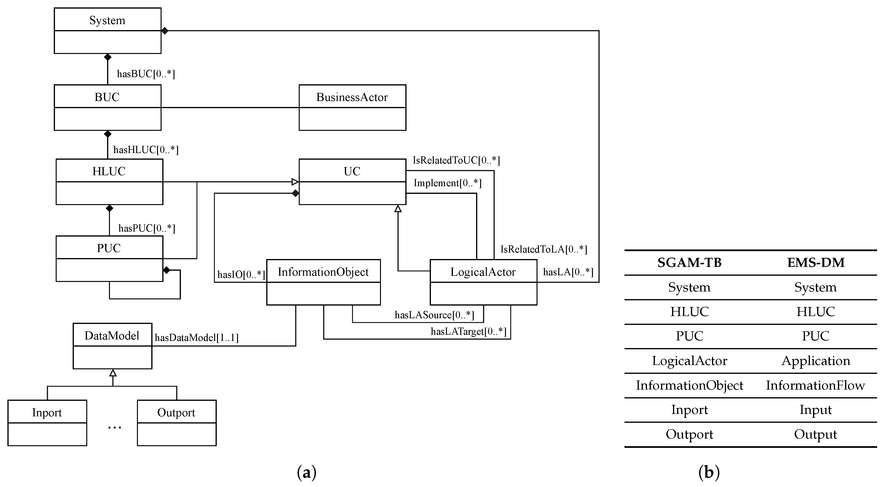
3.2.2. UML Representation of EMS-Ontology

Since models are the main concept behind MDE, the conception of models across the full development process is a main task to be supported by the EMSOnto expert. In this light, a model of EMS-ontology is achieved and exposed in this section.
OMG recommends the formulation of models by OMG specifications such as UML and SysML, among others [27]. UML, a widely used standard for describing structure and behavior of complex systems is selected to represent the models. On the other hand, the expressiveness needed by the EMS- T B o x is given by S R O I Q ( D ) , a logic defined within DL concept that provides complex role inclusion axioms, inverse roles constructors, qualify cardinality restrictions among others [28]. Thus, mapping rules to relate S R O I Q ( D ) elements to UML metamodel elements are established to conceive a UML model of the EMS- T B o x , see Table 1. A DL concept is transformed into a UML class, a concept subsumption into a UML generalization and so on, a practical implementation of those conversions is given in [29]. It is worth mentioning that the full T B o x cannot be expressed by a UML class diagram since not all the T B o x axioms can be transformed into UML elements (e.g., transitivity axioms, composition role constructor). The resulted UML class diagram is presented in Figure 4 and goes under the name of EMS-Data Model (DM). Only a simplify model is depicted. InformationFlow is a new concept derived from the EMSOnto extension, it will be introduced later in the paper.

4. Analysis of a Use Case Example by an EMSOnto Expert

Different mechanisms to enlarge the capabilities of EMSOnto were proposed above. This section outlines the role of the EMSOnto expert regarding the implementation of a specific UC.

4.1. Use Case to Be Analyzed by the EMSOnto Expert

The UC Customer Energy Management System (CEMS) was implemented using EMSOnto as a basis [8]. SGAM is the preferred approach among smart grid specification approaches as demonstrated in [4]. The SGAM information layer represent system’s components as well as their information flows. Moreover, it combines domain-axis and zone-axis to structure smart grid control applications. For the CEMS in this UC, a detailed model is provided as an SGAM description, as seen in Figure 5. This shows the main CEMS’s actors (i.e., BESS, CEMS, Meter, etc.) and the scope of the CEMS, which is located at the customer side and at the station level.
The CEMS is embedded with Frequency-Watt (FW) and Self-Consumption (SelfC) services. Both services control the active power injected/subtracted by the BESS. To this aim, the signals State of Charge (SoC) ( S o C b a t ) and active power ( P b a t ) are retrieved from the BESS. In turn, the frequency ( F g r i d ) and active power ( P g r i d ) at the Point of Common Coupling (PCC) are taken from a smart meter. Generation of a PhotoVoltaic (PV) DER and the consumption of a household impact the behavior of the CEMS. Thus, they are also considered during design stage. After execution of the SelfC and FW services, a calculated active power setpoint ( P r e f ) is sent to the BESS.

4.2. Requirements from Control Engineers

The CEMS is implemented with EMSOnto. Control engineers in charge of the implementation employs specific tools for power systems emulator (MATLAB/Simulink) and controller platforms (IEC 61499 platform) [20,30]. Furthermore, not only specific tools but specific documents (IEC 61850 SCL files, SGAM models) were used for the description of IED’s functionalities and control applications architecture. This is due to common practices of control engineers. Nevertheless, other tools and frameworks are also available to support the engineering process of power systems (e.g., Modelica and IEC 61131-3) [31,32] as well as other information models for smart grid networks (e.g., CIM) [33]. The fact of using specific tools to evaluate the proposed methodology would enable a concrete understanding of the actions taken by the EMSOnto expert.
A series of requirements that motivates an expansion and customization of EMSOnto were figured out by control engineers. These requirements are bound to specific tools, documents and information models as exposed below.
(R1) Benefiting from SGAM models: CEMS is roughly described at the specification stage by means of the SGAM-TB. The information added at that stage is reused at design time to fill the EMS-templates. Therefore, an automatic import of SGAM models into EMS-templates is expected with the aim of reducing the manual work conducted by control engineers.
(R2) Discovering CEMS constraints: The controlled process (i.e., the BESS) is surrounded by constraints that characterizes technical limitations of electrical devices and/or safety restrictions. Those constraints need to be considered during design of control strategies. Therefore, an understanding of them is absolutely required during design time. Hence, an automatic retrieval of constraints from the process is expected.
(R3) SoC estimator function generation: In the scope of multi-functional BESS, the battery provides support not only to an individual service, but more than one. In this context, a solution to track the delivered active power of the BESS to a specific service is performed by control engineers. This consists on the calculation of SoC per service by a function called S o C _ e s t i m a t o r . As a result, this function is implemented whenever a UC controls a BESS. Hence, an automatic generation of the S o C _ e s t i m a t o r function is sough in the scope of R3.
(R4) Generation of configuration files: EMS and IEDs need to be parametrized and customized to specific requirements and initial state values. A selection of parameters is gathered in a sort of configuration file that is filled out before any execution or simulation of the mentioned systems. These configuration files support the validation of the EMS through the proof-of-concept and implementation phases. R4 seeks for an automatic generation of such files, which should expose the parameters of functions to be deployed within an EMS as well as the IED’s parameters.
(R5) Identification of batteries mismatching services: A service that request BESS support would ask to fill certain requirements such as capacity (kWh), maximal power provision (kW), activation time (s) [34,35]. Thus, not all the BESS would pass the pre-qualification procedures defined by network operators. BESS able to participate in Primary Control Reserve (PCR) should provide certain power. A report that identifies BESS that do not meet this requirement is expected.
(R6) Generation of IEC 61499 models: The design of CEMS is validated within a power system emulator as part of the proof-of-concept. Following this step, the implementation of it is performed within a controller platform fully compliant with IEC 61499. On the other hand, some components of the CEMS (e.g., communication interfaces, control logic) were directly tested in the controller platform. This motivates an automatic generation of the IEC 61499 control application either from EMS-templates or from the MATLAB/Simulink project.
(R7) Benefiting from IEC 61850 ICD files: Power system information models hold data important for the IDE and UC repository. In the scope of CEMS, Information Capability Device (ICD) files are handled to control engineers. ICD files are XML-based, which serialize information regarding functions supported by an IED and are often supplied by the IED manufacturer. Thus, R7 seeks for an automated import of ICD files into the repository.
(R8) Identification of misconfigured units: An EMS controlling and monitoring an IED (e.g., BESS) should be aligned to the units of the IED. In other words, a control signal targeting a setpoint should respect the units of the value to be targeted. Otherwise, a wrong value would be set. This applies also to a status been monitored by feedback. For instance, a BESS is providing its SoC status ( S o C b a t ), which has the value of 80%. An EMS retrieving this value may expect raw data between the range 0–1 (0.8). This mismatch between units would cause a wrong behavior of the EMS. Hence, an identification of such inconsistencies is fundamental.

4.3. Analysis Phase: Analysis of Requirements

An analysis of the mentioned requirements determines the actions to be performed by the EMSOnto expert. This analysis is structured under a succession of steps. The first step corresponds to investigate where the transformation across data models takes place. This corresponds to R1, R4, R6 and R7. Those requirements involve different data models that need to be interrelated with EMS-DM. Therefore, data models of SGAM, IEC 61850, IEC 61499 and Matlab/Simulink are studied and an alignment of EMD-DM to the referred data models is sought. Following this, classes and associations not considered within EMS-DM are created and added to it, affecting the EMS- T B o x .
The next step is to identify requirements clearly connected to the inference of knowledge. R2, R3, R5 and R8 correspond to this category. A complete understanding of the knowledge to be inferred in the scope of those requirements is needed. Thereby mathematical models representing constraints within a control application (R2) are investigated as well as models that drive the operation of S o C _ e s t i m a t o r function (R3). Furthermore, an understanding of technical limitations within a BESS are also needed (R5) just as information models that conduct the structure of sources and targets defined within information flows (R8). In the aftermath, the T B o x is again extended to cope with R2, R3, R5 and R8. Eventually, the creation of queries and rules could also take place.

4.4. Realization Phase: Implementations Performed by EMSOnto Expert

The actions taken by EMSOnto expert are highlighted and enumerated in Figure 6. The first step is dedicated to the creation of new concepts, roles, and constraints within the EMS- T B o x . The expressivity of EMS- T B o x depends on the ontology language used to implement it (e.g., OIL, DAML+OIL, OWL 2 [36]). In case that a higher expressivity is needed the implementation of rules is carried out as part of the next step.
As a sequel, population of the EMS- T B o x is done against assertions of the CEMS use case, hence, CEMS knowledge is collected within EMS-templates. EMS-templates are complemented with the information from SGAM models and ICD files. To achieve this, a mapping between the SGAM model and the EMS-DM is performed, as well as a transformation between IEC 61850 models (ICD files) and EMS-DM. When a complete A B o x is reached the inference of knowledge takes place. Queries are built upon the inferred knowledge to allow the identification of inconsistencies. Finally, the EMSOnto expert establishes M2M and M2T transformation to generate software artifacts as depicted in Figure 6. The implementation of the aforementioned actions are carried out by Semantic Web Technologies, ontology editors and programming frameworks. A detail of the aforementioned actions is addressed below.

4.4.1. Action 1: Extending the EMS-Ontology

Ontology Web Language (OWL) 2, a popular ontology language recommended by the World Wide Web Consortium (W3C) is chosen to implement the expressivity required by EMS- T B o x ( S R O I Q ( D ) logic) [37]. OWL 2 is based on S R O I Q and furthermore it supports data types. Thus, a complete implementation of the T B o x is reached. On that basis, concepts, roles, and axioms not considered within the EMS- T B o x are investigated and addressed in this section.
R1 seeks to benefit from UML behavior and structure diagrams specified with the SGAM-TB. Because of that, a concordance between SGAM-TB and EMS-DM should be reached. The EMS-DM focuses on function and information aspects of smart grid control applications. Thereby, the business, communication, and component SGAM layers are out of the scope. The function analysis of SGAM-TB involves different concepts, such as High-Level Use Cases (HLUC), Primary Use Cases (PUC), Logical Actors (LA) [38]. Those concepts are already included in the EMS-DM. However, the concept Information Object (IO) that represents communication between LAs and PUCs was not yet addressed. Hence, it is added to the EMS-DM under the name of InformationFlow, which stands for the UC’s information that relates one Output to one Input as exposed in Table 2 and Figure 4.
An investigation of mathematical models for IEDs is carried out in the scope of R2. For simplicity, a single-output and single-input process is represented in state space as shown in Equation (1). Where u is the input variable, y is the process output and x the state vector with dimension n× 1 that represent the entire state of the process at any time. In the scope of our study, the process is represented by electrical devices connected along the low voltage distribution grid, such as BESS, PV, load, etc. These processes are frequently surrounded by constraints on control variables (u), state variable ( x ), or output (y), as described by Equation (2). A control application (i.e., CEMS) that intends to manipulate outputs of the process (y) needs to respect the referred constraints.
From an IED’s perspective, an instantiation of previous data with EMS- T B o x concepts is achievable: Setpoint (u), Manipulated (y), State { x 1 , …, x n }, Constraint { u max , }. In this work, only constraints on setpoint variables ( u min , u max ) are inferred, the others (e.g., y max ) follow a similar mechanism. On that basis, the CEMS infers constraints from the IED’s setpoints. To achieve this, the concept Constraint is further developed as depicted in Table 3, where Variables defined within a Constraint are modeled as well as the relation between Constraints.
x = A x + B u , y = C x + D u , x = [ x 1 x n ] T
x min x x max , u min u u max , y min y y max
The generation of the S o C _ e s t i m a t o r function is contemplated in R3. Thereby, an analysis of data that conforms such function is carried out. Considering a HLUC controlling the active power supplied by a BESS, the calculation of HLUC’s SoC ( S o C h l u c ) follows the logic in Equation [3]. S o C h l u c  depends on the SoC initially assigned to the HLUC ( S o C i n i ), the current charged into the BESS ( I b a t ), as well as the total capacity of the BESS ( Q b a t ) and a portion capacity assigned to the HLUC ( Q h l u c ). The value I b a t is calculated from the active power ( P b a t ) and the nominal voltage ( V n o m ) of the battery. A modeling of the mentioned variables results in the following instantiations: State{ V n o m , S o C }, ParamDevice{ S o C i n i , C A h } and ParamUC( C A h _ U C ). Nevertheless, a further representation of those variables is required, resulting in new concepts. For instance, the concept Vnom represents nominal voltages and is subsumed by State. A detail of all those new concepts is given in Table 4.
On the other hand, the creation of new roles facilitates the generation of S o C _ e s t i m a t o r . Hence, ControlBESS relates a UC controlling a BESS and the concrete role hasI_O facilitates a remote control of internal variables defined within the scope of a UC as detailed in Table 4.
S o C h l u c = S o C i n i + I b a t Q b a t Q h l u c , I b a t = P b a t V n o m

4.4.2. Action 2: Enlargement of Inference Process

The inference of data reached by OWL ontologies can be extended by Semantic Web Rule Language (SWRL). This concept is standardized by W3C as language for expressing rules and provides powerful deductible reasoning mechanisms compared to OWL. SWRL is based on OWL DL, Datalog and Horn-like rules [39]. As a result, the syntax of SWRL is represented by atoms, rule body (antecedent) and rule head (consequent): A t o m A t o m A t o m . If the conditions on the antecedent hold, then also the conditions in the consequent hold. On that basis, SWRL rules r 1 and r 2 are designed to support the identification of CEMS’s constraints, as shown in Table 5. Where r 1 deduces Variables assigned to Constraints and r 2 infers relations between Constraints.
On the other hand, certain rules that requires the creation of new instances, in the consequent that these do not appear in the antecedent, are not possible by SWRL. In those cases, SPARQL Update queries are used instead [40]. SPARQL Update is a standard language that executes updates to triples in a graph store. It uses the data operators INSERT and DELETE for inserting and removing triples.
Following that, mechanisms to generate the S o C _ e s t i m a t o r function use r 3 to identify when a HLUC is controlling a BESS by means of ControlBESS. As a sequel, r 4 attaches a new PUC ( S o C _ e s t i m a t o r ) to the identified HLUCs. Finally, r 5 is responsible for the connections across the BESS, the HLUC and the created PUC ( S o C _ e s t i m a t o r ). Those rules are detailed in Table 6.

4.4.3. Action 3: Setting up of New EMS-Templates

This section addresses all the modifications carried out along EMS-templates to keep a consistency with the extended EMS- T B o x . The extended headlines are highlight with blue color.
The detection of CEMS’s constraints would need to gather instances of these general statements: a UC (s) contains a Setpoint (x), which in turn is constrained by Constraint ( C 1 ). Moreover, a Constraint ( C 1 ) is related to a Constraint ( C 2 ). Thereupon, an extension of the spreadsheet template collecting the UC’s attributes is performed and resulted in Table 7. Moreover, the field Const_Description is included to gather constraint’s descriptions.
The vocabulary defined to model the S o C _ e s t i m a t o r involves variables of BESS and UCs. The current version of EMS-templates contemplates generic models of BESS and UCs. Nevertheless, those models need to be extended to achieve the implementation of the S o C _ e s t i m a t o r as shown in Table 8. For instance, the concept CAh_UC that represents the capacity assigned to a UC is now included in the UC( U C _ g e n e r i c ), just as the CAh concept in the UC( B E S S ). Besides this, a complete model of PUC( S o C _ e s t i m a t o r ) is also required, see Table 9. All the extended models are made available in the IED and UC repository. Hence, control engineers are free to edit all the fields except Type.

4.4.4. Action 4: Mapping Between SGAM-TB and EMS-DM

The exchange of data between SGAM models and EMS-templates is addressed using MDA techniques. Hence, a model of SGAM-TB is investigated and proposed in this section.
A UML class representation of SGAM-TB is suggested by Neureiter et al. [38]. Such representation motivates the SGAM-TB model proposed in this work. It is worth highlighting that only function and information layers are modeled. The function layer of SGAM-TB involves description of main functionalities within the concept HLUC, further details of HLUCs are given in PUC. Actors involved within those PUCs are modeled by the LogicalActor. In turn, the information layer includes the InformationObject a concept representing any information flow. Which is structured by a data model (DataModel). The aforementioned concepts are combined to conceive a UML class representation of SGAM-TB, see Figure 7a. Considering this, classes, attributes, and other components of SGAM-TB model are transformed into EMS-DM components, as shown in Figure 7b. For a straightforward interpretation only the mapping between classes is depicted.

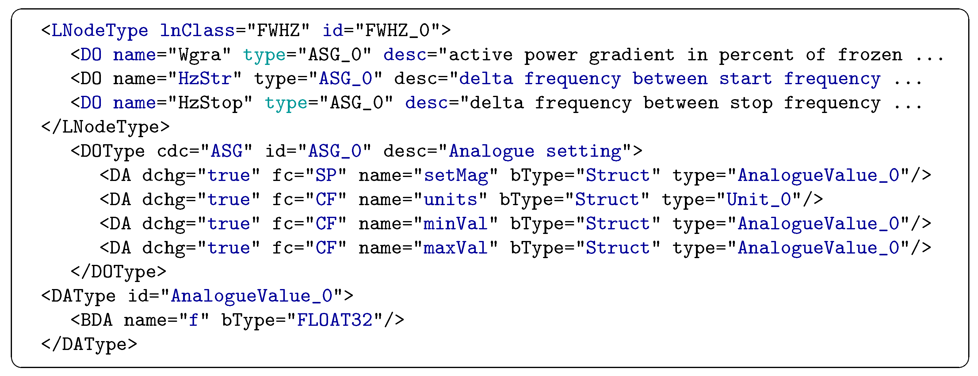
4.4.5. Action 5: Mapping Between IEC 61850 an EMS-DM

The IEC 61850 approach is object-oriented and has been lately used in power system domain to improve interoperability between IEDs. The abstraction of services provided by an IED begins with a Logical Node (LN), which models services for protection, measurement, control, etc. Each LN is defined as a class within the IEC 61850-7-4 specification [41]. Data Objects (DO) refine the definition of a LN, they are specified by Common Data Classes (CDC) in IEC 61850-7-3 [42].
On the other hand, IEC 61850 defines a language to configure IEDs under the name of System Configuration Language (SCL) in IEC 61850-7-6. An SCL specifies the capabilities of an IED by LN classes, which are of type LNodeType. Each of them contains DOs of type DOType which in turns contain DAs of type DAType. A LNodeType should correspond to a LN as well as a DOType to a CDC.
The instantiation of the mentioned classes is exemplified by the LNodeType: M M X U , see Figure 8. This notation (class:individual) is employed to assign an individual to a class. The mentioned LNodeType represents a calculation of current, voltage, frequency, etc. Thereby, it contains among others the DO: H z for frequency measurement. This DO contains DA: m a g to abstract the mean value of the frequency.
On the basis of SCL representation, the mapping between EMS-DM and IEC 61850 is carried out as follows: a LNodeType is transformed into a UC and a DO into a Variable. The type of Variable (i.e., Feedback, Control, etc.) to be generated is obtained from the attribute c d c within DOType. Hence, a  M V (Measured Value) results in a Status assigned with a Numeric value. The DAs elements of a DOType (i.e., t, mag, units, etc.) are mapped into the attributes of Numeric (i.e., hasTimeStamp, hasAnaValue, hasUnits, etc.). Those mappings are referenced by color match in Figure 8.
In the previous example a DO: H z representing a MV resulted in a Status. However, a DO may belong to the other types such ASG (Analogue Setting) or SPS (Single Point Status) among others. Depending on that, a generation of either a Setpoint or Status, etc. is performed. It is worth highlighting that not all the DAs of a DOType can be mapped into the EMS-DM. For instance, the DA: q that represents the quality of the information is not mapped. To accomplish that, an extension of attributes assigned to Variable is required. As a summary, any IED functionality defined within a LN is translated into a UC and upload into the repository.

4.4.6. Action 6: Generation of Inconsistency Reports

The identification of certain inconsistencies may require the extension of the EMS- T B o x as well as definition of new rules and queries besides adjustments to the EMS-templates. However, the fulfillment of R5 and R8 requires just the elaboration of new queries, those are addressed as follows. In the scope of R5, constraints on a BESS are analyzed. The active power value of a battery is limited as shown in Equation [4]. The identification of services that attempt to control P b a t with values that exceed the technical limits requires the modeling of P m a x . Besides this, the power demanded by a service is also needed ( B e s s S i z e ). Those concepts were already included in the EMS- T B o x .
A formalization of competency questions is achieved by DL or SPARQL queries [43]. This depends on the type of question, usually elaborated questions need the expressivity of SPARQL syntax. In turn, simple questions can be formulated by DL. On that basis, R5 implies DL queries to answer questions about BESS’s restrictions and UC’s parameters, see Table 10.
P min < P b a t < P max
On the other hand, since R8 investigates misconfigured units, an analysis of the information flow is required. An information flow is conformed by a source and a target. A source can be of type Control and Output. In turn, a target is of type Setpoint and Feedback. Units of the source should match the units configured at the target. Enough information is already provided within the EMS-templates to conclude mistaken units. The SPARQL query in Table 11 investigates and compares units within a Setpoint and Control.

4.4.7. Action 7: Software Artifacts Generation

This section tackles the issues exposed in R4 and R6. Therefore, an automatic generation of configuration files and software artifacts compliant with IEC 61499 is pursued.
The achievement of a configuration file from EMS-templates is carried out by M2T transformations. Hence, the model source is given by EMS-DM and the text target is defined by control engineer’s practice. As an example, a MATLAB script that supports the proof-of-concept of CEMS is sought. Such script should expose parameters within a HLUC. Hence, a M2T is implemented by Acceleo templates, an open source framework for code generation, see Figure 9. That Acceleo template investigate all HLUCs (i.e., functions) included within an EMS. Afterwards, the parameters (Param) assigned to the identified HLUCs are extracted and customized.
The proof-of-concept of CEMS is also supported by generation of MATLAB/simulink models. A generation of MATLAB/Simulink applications from EMS-templates is based on M2M transformation where the PIM is given by EMS-DM and the PSM by a MATLAB/Simulink model. As first step, a conception of MATLAB/Simulink model should be reached, this model is proposed within the MATLAB Simulink Integration Framework for Eclipse (MASSIF) project [44]. The root of that model is SimulinkModel, which contains Block and SubSystem. A SubSystem is characterized by properties and ports of type Outport and InPort. Those ports may be related to a SingleConnection. This configuration is quite similar to EMS-DM structure. Hence, the concepts: Application E M S and UC E M S are transformed into SubSystem S i m , Input E M S into InPort S i m , InformationFlow E M S into SingleConnection S i m and so on, as shown in Table 12. To increase the understanding of classes transformation the syntax class M o d e l is used.
An automatic generation of IEC 61499 applications from EMS-templates requires a model representing IEC 61499 applications. A UML class representation of it is reached from an analysis of the standard IEC 61499 [45], see Figure 10. As it can be noticed the depicted model share many similarities with the EMS-DM, thus a matching between them is possible as shown in Table 12. A  UC E M S is mapped to a FB 61499 , which is defined by a FBType 61499 . The FBType can take the form of one single block (BasicFB) or an arrangement of blocks (FBNetwork), see Figure 10. On the other hand, Application s E M S is converted into Application 61499 , Input s E M S into InputVars s 61499 and so on.
Model-to-model transformation across MATLAB/Simulink, IEC 61499 and EMS-DM can be implemented by following the mappings referenced in Table 12. This gives a flexibility to transform EMD-DM instances (i.e., EMS-templates) into specific platforms important to the proof-of-concept and implementation phases. Transformation rules are carried out using ATL Transformation Language (ATL), a M2M transformation language that implements unidirectional transformations within the Eclipse platform [46]. To illustrate this, the rules to transform UC E M S into FBType 61499 are shown in Figure 11. Where a navigation through the components of FBType (i.e., InputVars, OutputVars, InternalVars) enables a match to EMS-DM elements (i.e., Input, Output, Param).

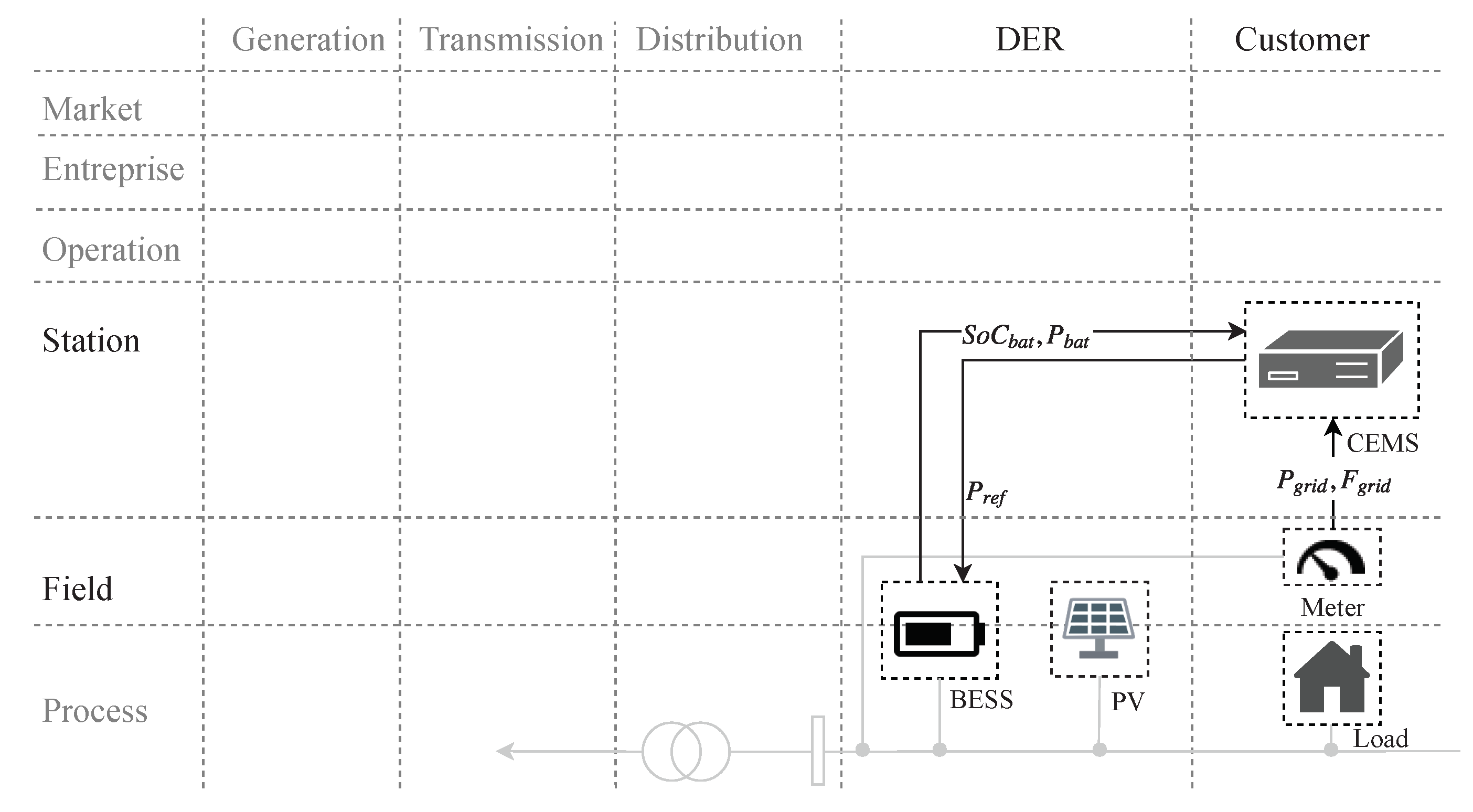
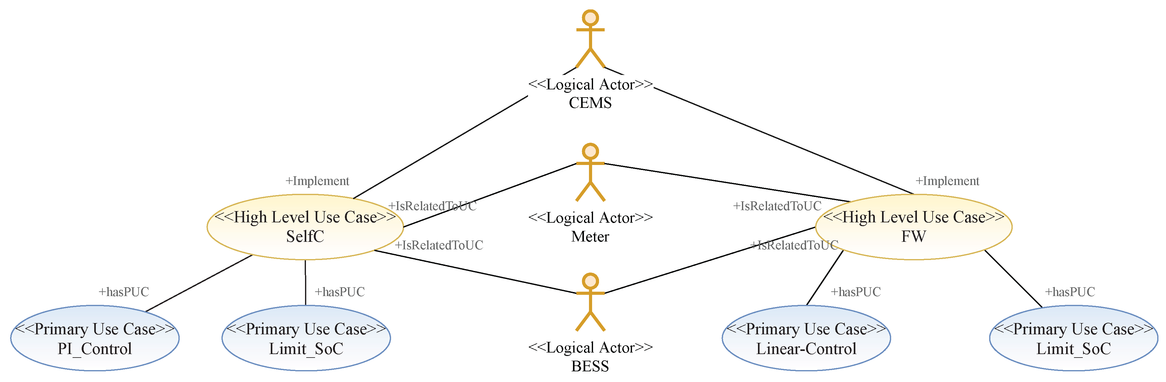
5. CEMS Implemented with the Extended EMSOnto

This section shows how the above presented improvements of the EMSOnto are used by control engineers during the realization of a CEMS.

5.1. EMS-Templates

The previously introduced CEMS is specified using SGAM-TB, which is available as an extension of the design tool Sparx Systems EA, thus UML and SysML support the CEMS design. Hence, the structure of the CEMS is specified under UML use case diagrams, the resulting model is depicted in Figure 12. From such a representation it is deduced that the CEMS implements S e l f C and F W , which are associated with a M e t e r and a B E S S . Moreover, S e l f C implements the functions P I _ C o n t r o l and L i m i t _ S o C just as F W implements L i n a r - C o n t r o l and L i m i t _ S o C . All those details define the CEMS structure and should be considered at the design phase. To support this, an automatic transfer of information from SGAM models to EMS-templates is executed. This involves UML use case, sequence, and activity diagrams. The resulted EMS-template from a use case diagram is shown in Table 13. This represents a first version of the EMS- A B o x and the starting point of the design process.

5.2. UC and IED Repository

At the design phase, ICD files provided by the IED’s manufacturer are available to the control engineers. Selected ICD files are imported into the UC repository to benefit from IED and UC models.
A reduced model of an ICD file containing the LN: F W H Z is illustrated in Figure 13. A detail description of that LN is available in IEC 61850-90-7 [47]. The XML file shows variables within the LN: F W H Z , which are represented as DO elements. Attributes of those variables are contained within the DOType identified under A S G _ 0 . Those attributes are of type A n a l o g o g u e V a l u e _ 0 and own values of type F L O A T 32 . With that in mind, it is understood that LN: F W H Z contains the variables W g r a , H z S t r and H z S t o p . Each of them owns a series of attributes: s e t M a g , u n i t s , m i n V a l and m a x V a l which are of type F L O A T 32 . The exposed LN: F W H Z is transformed into PUC( F W H Z ), afterward this PUC is load into the UC & IED repository, thus accessible to control engineers.
Since the operation followed by the LN: F W H Z is similar to PUC( L i n e a r - C o n t r o l ), it is worth setting the PUC’s type to F W H Z . As a result, all the variables related to LN: F W H Z are imported within L i n e a r - C o n t r o l , see Table 14. However not all the attributes’ values are collected (e.g., min, max, unit), this is because those values are set during real-time operation of IEDs.

5.3. Constraints of the CEMS

The inference of CEMS’s constraints entails a collection of technical limitations regarding the process to be controlled (i.e., DERs, IEDs). This means that IED’s constraints are documented within the extended EMS-templates. Once this process is complete, IED models are upload to the repository and CEMS’s constraints are automatically resolved.
As an example the BESS’s constraints are inferred. The BESS model is built by control engineers, see Table 15. As it can be noticed, the BESS owns the variables active power ( P b a t ) and apparent power ( S b a t ). The active power is set by Setpoint( s p _ P r e f ). This statement is exemplified by the role IsAssignedBy. Moreover, constraints on the BESS are detailed. Hence, C 1 represents a constraint on P b a t and C 2 a constraint on S b a t . Since S b a t and P b a t are constrained by P b a t 2 + Q b a t 2 S b a t 2 the relation IsConsLinkCons( C 1 , C 2 ) is established. The resulted BESS is upload to the repository. Next, a reasoner engine is executed, and new knowledge is provided to the control engineers. One of those results corresponds to PUC( L i m i t _ S o C ) being limited by the constraints C 1 and C 2 . This implicit data is highlight with blue color in Table 16. The role IsAssignedTo is the inverse of IsAssignedBy.

5.4. Inconsistencies Report

Inconsistencies reports are generated from querying the CEMS’s inferred data. The original EMSOnto already supports reports of conflicts between UCs [8]. On top of that, the extended EMSOnto allows the identification of further inconsistencies such as BESS mismatching a service ( I I ) and misconfigured units ( I I I ). During the design process the report shown in Table 17 was provided to control engineers. The report shows I I I as an identified mismatch, which led to a correction of the unit configured within Control( c t _ P r e f ), a control signal targeting the setpoint ( s p _ P r e f ) of the BESS.

5.5. SoC Estimator Function

Since F W and S e l f C are controlling the BESS they need to estimate how much power was delivered by the BESS. This is reached by instantiating the function S o C _ e s t i m a t o r and attaching those instances to HLUC{ F W , S e l f C }. EMSOnto provides an automatic creation of PUC( F W _ S o C ) and PUC( S e l f C _ S o C ) as shown in Table 18. The PUCs are instances of S o C _ e s t i m a t o r and therefore share the same attributes (e.g., C A h _ U C , I). This new information is highlighted by blue color.

5.6. Software Artifacts Generation

An automatic generation of the MATLAB script shown in Figure 14 is performed. Only the parameters’ values are generated. Other attributes such as format and unit are dismissed. Moreover, a refinement of the code was not necessary and it was used as it was generated. This script supports the proof-of-concept of the CEMS simulated within a MATLAB/Simulink platform [8].
On the other hand, the validated CEMS is transformed into IEC 61499 models, the ensemble of function blocks focused on HLUC( F W ) is shown in Figure 15. A refinement of the obtained model consisting on the replacement of function blocks is carried out. Furthermore, two clients simulating the communication with real BESS and meters are generated but not configured ( B E S S and M e t e r ).

5.7. Evaluation of Requirements and Open Issues

This section exposes how the open issues stated in Section 2.4 are addressed by analyzing the implementation of the selected use case example (CEMS).
Documents available at design phase are exploited: The previous experiments regarding the CEMS demonstrate an automatic processing of documents intended to support the CEMS design. In other words, knowledge structured under information models (IEC 61850) and specification approaches (SGAM) are collected to populate EMS-templates.
SGAM models provide a high amount of information regarding the specification of an EMS. Since the design should implement a solution according to EMS specifications, SGAM models were imported within EMS-templates. As a result, at the design phase control engineers starts with a design totally aligned with the requirements defined by stakeholders. Another benefit of this, is that potential manual errors, susceptible to be introduced by manual input of EMS-templates, are avoided. Furthermore, it has been demonstrated that by model-driven engineering techniques it is possible to employ SGAM models in a computerized way to support the whole engineering process. This corresponds to the use of SGAM knowledge for the generation of software artifacts. Nevertheless, the presented experiments did not consider other specification approaches such as Intelligrid and UML. Getting information derived from such approaches would imply to carry out a formal data representation as well as transformation rules and maybe extensions on the EMS- T B o x as it was done with SGAM. The fact of proving an alignment between SGAM and EMSOnto sets the basis for other possible alignments.
Another executed experiment corresponds to the import of IEC 61850 SCL files into the IED and UC repository. IEC 61850 suggests not only power system components but also IED functionality. In that regard, the PUC( L i n e a r - C o n t r o l ) is successfully generated from the LN  F W H Z . Only the LN’s attributes required by engineers were covered in the experiments. However, since the EMS- T B o x does not contain all the classes and attributes defined within IEC 61850 a full import of the LN’s attributes would involve a further extension of the EMS- T B o x .
The successful import of SCL files attempts to demonstrate that power utility information models can be used to feed the UC and IED repository. This means that the same mechanisms used to import IEC 61850 models are expected for other models such as energy market communication models formalized in IEC 62325 and also smart meter models defined within IEC 62056 among others [48].
Enlargement of inferred knowledge: Inferences provided by EMSOnto were extended. The inferences performed in this work support control engineers by deducing the constraints to be respected. Besides this, the identification of inconsistencies that may harm the correct operation of control applications was carried out. On top of that, new functions ( S o C _ E s t i m a t o r ) were created to accelerate and support the design of control applications.
Since different sort of inferences were achieved this may lead to think that EMSOnto is flexible to implement any kind of inference. However, this strictly depends on the expressivity provided by the ontology ( S R O I Q ( D ) ) and also the rules. Although S R O I Q ( D ) is well defined, the expressivity for rules is determined by rule languages. In this work, SWRL and SPARQL were enough to address the control engineer’s requirements. Nevertheless, other requirements may need to use the Rule Interchange Format (RIF), which provides the means to insert primary logic programming languages [37], or even to extend ontologies with probabilistic inference and temporal logic [49].
Flexible generation of software artifacts: CEMS experiments demonstrate that generated code and models support control engineers not only in the proof-of-concept but also during the implementation phase. To make this possible, mappings between a power system emulator (MATLAB/Simulink), a controller platform (IEC 61499 platform) and Emsonto are conceived as well as text templates for code generation (MATLAB script). This evaluation lays the groundwork for implementations to other specific platforms (IEC 61131-3, PowerFactory).
The final realization of control applications requires the participation of engineers for the customization of generated models as well as the definition of the control algorithm’s behavior. In the use case example, communication interfaces were generated ( B E S S and M e t e r clients), although not configured. Consequently, the generation of a full control application ready to be tested is not fully automated. Indeed, other approaches cover those gaps. For instance, PSAL supports the design and implementation of communication and component layers [10]. Therefore, the cooperation between different engineering and development approaches is encouraged.

6. Conclusions

In the near future, a high integration of BESS within the distribution grid may very well become a reality since they can provide a broad range of services. Those services are likely to be deployed within an EMS which in turn will control the active and reactive power of a BESS. In that context, this work seeks an automated and adaptable approach that would support the engineering process of such EMS. Therefore, available engineering approaches are studied to realize what are the open issues to be addressed. Among the studied approaches, EMSOnto—a holistic approach for multi-functional BESS—is selected as the reference methodology.
The identified open issues are handled by the EMSOnto expert, whose main role is the customization of the EMSOnto according to control engineer’s requirements. As a solution, the expert proposes a set of actions based on model-driven engineering techniques and ontologies. Those are summarized as the extension of the EMS- T B o x , setting up of new rules and queries, extension of EMS-templates, and finally the conception of data models and transformation rules. All those actions are exemplified by a selected use case example showing the realization of a CEMS, which encapsulates a series of control engineering requirements. The realization of the CEMS allows to evaluate the efficacy and limitations of the proposed solutions. The experiments were tied to specific tools and standards (MATLAB/Simulink, IEC 61850, IEC 61499, SGAM) to show the EMSOnto expert’s actions. These experiments set foundations for further customizations of EMSOnto with the aim of encompassing other standards and tools. An analysis of the tasks performed by the EMSOnto expert, after collecting and understanding the control engineer’s requirements, is outlined, and discussed:
  • Define an ontology/data model of the EMS under study
  • Integrate rules and queries to the ontology
  • Propose a methodology to gather knowledge from the EMS
  • Design data models for specific software platforms, IEDs, DERs, etc.
  • Elaborate transformation rules for code/text and model generation
From the abovementioned steps, only steps 4 and 5 should be carried out to exploit information sources available at the specification stage. This is demonstrated by the CEMS example, where EMS-templates are fed with SGAM models. Hence, a consistency between specification and design phases was reached. Similarly, the abovementioned steps can also be applied to other specification and design approaches such as IntelliGrid, PSAL, etc. On the other hand, by following steps 1, 2 and 3 the inference of implicit knowledge is achieved. It was demonstrated by detecting inconsistencies within multi-functional BESS (e.g., misconfigured units) and by deducing functions at the design time (e.g., S o C _ e s t i m a t o r ). The proposed methodology can enable inference within other modern approaches (e.g., PSAL) as well. Besides this, a customized generation of software artifacts is achieved by performing steps 1, 4 and 5. As a result, EMSOnto is now able to support the implementation stage with generated code aligned to a controller platform (IEC 61499). In the same way, other approaches can also benefit from the referred steps to achieve compatibility with different specific platforms.
From the CEMS use case example, it is worth noticing that limitations of inferences depend on the expressivity of the ontology (e.g., OWL ontology) and the intelligence provided by rule languages. Consequently, it is encouraged to choose the right ontology language for the handling of the knowledge to be inferred. Moreover, the validation of EMS involves a dynamic process. Therefore, the identification of certain inconsistencies at that stage would require the time notion, which in a future work can be achieved by extending the expressiveness provided by ontologies with temporal logic [50]. On the other hand, with the current approaches, it is common to document the planned design (e.g., PSAL, SGAM, EMSOnto). Modifications to the stipulated design occurs often during proof-of-concept and implementations stages. However, since the modified information is not tracked then the generated software artifacts would not be aligned with the final validated design. To handle that issue, reverse engineering along the engineering process is encouraged [51]. Moreover, the validation of multi-functional BESS applications often involves tools such as communication networks and co-simulation frameworks. This means that the communication and component domains should be considered by the selected approach. However, this is not always the case since the mentioned domains are not modeled within EMSOnto. Thereby, as future work it is encouraged to combine different approaches, for instance, combining EMSOnto with PSAL where a formal semantic for communication interfaces and components is addressed.

Author Contributions

C.Z. wrote the paper and carried out the conceptualization, investigation and validation of the work. F.P.A. and T.I.S. participated in the conceptualization of the proposed approach and reviewed the final manuscript. T.I.S. supervised the overall work.

Funding

This work is partly supported by the Austrian Ministry for Transport, Innovation and Technology (bmvit) and the Austrian Research Promotion Agency (FFG) under the ICT of the Future Programme in the MESSE project (FFG No. 861265).

Conflicts of Interest

The authors declare no conflict of interest.

References

  1. Alizadeh, M.; Parsa Moghaddam, M.; Amjady, N.; Siano, P.; Sheikh-El-Eslami, M. Flexibility in Future Power Systems with High Renewable Penetration: A Review. Renew. Sustain. Energy Rev. 2016, 57, 1186–1193. [Google Scholar] [CrossRef]
  2. Koller, M.; Borsche, T.; Ulbig, A.; Andersson, G. Review of Grid Applications with the Zurich 1MW Battery Energy Storage System. Electr. Power Syst. Res. 2015, 120, 128–135. [Google Scholar] [CrossRef]
  3. EERA Joint Programme on Smart Grids-Sub-Programme 4-Electrical Energy Technologies; Technical Report D4.3 Integration of Storage Resources to Smart Grids: Possible Services, D4.4 Control Algorithms for Storage Applications in Smart Grid; EERA: Brussels, Belgium, 2014.
  4. Zanabria, C.; Pröstl Andrén, F.; Strasser, T.I. Comparing Specification and Design Approaches for Power Systems Applications. In Proceedings of the 2018 IEEE PES Transmission and Distribution Conference and Exhibition—Latin America, Lima, Peru, 18–21 September 2018; p. 5. [Google Scholar]
  5. Santodomingo, R.; Uslar, M.; Goring, A.; Gottschalk, M.; Nordstrom, L.; Saleem, A.; Chenine, M. SGAM-Based Methodology to Analyse Smart Grid Solutions in DISCERN European Research Project. In Proceedings of the 2014 IEEE International Energy Conference (ENERGYCON), Dubrovnik, Croatia, 13–16 May 2014; pp. 751–758. [Google Scholar] [CrossRef]
  6. Working Group Sustainable Processes (SG-CG/SP). CEN-CENELEC-ETSI Smart Grid Coordination GroupSustainableProcesses; Technical Report; CEN-CENELEC-ETSI: Brussels, Belgium, 2012. [Google Scholar]
  7. International Electrotechnical Commission (IEC). IEC 62559-2 Use Case Methodology-Part2: Definition of the Templates for Use Cases, Actor List and Requirement List; IEC: Geneva, Switzerland, 2015. [Google Scholar]
  8. Zanabria, C.; Pröstl Andrén, F.; Kathan, J.; Strasser, T.I. Rapid Prototyping of Multi-Functional Battery Energy Storage System Applications. Appl. Sci. 2018, 8, 1326. [Google Scholar] [CrossRef]
  9. Zanabria, C.; Pröstl Andrén, F.; Kathan, J.; Strasser, T. Approach for Handling Controller Conflicts within Multi-Functional Energy Storage Systems. In Proceedings of the CIRED-Open Access Proceedings Journal, Glasgow, UK, 12–15 June 2017; pp. 1575–1578. [Google Scholar]
  10. Andrén, F.P.; Strasser, T.I.; Kastner, W. Engineering Smart Grids: Applying Model-Driven Development from Use Case Design to Deployment. Energies 2017, 10, 374. [Google Scholar] [CrossRef]
  11. Tayyebi, A.; Bletterie, B.; Kupzog, F. Primary Control Reserve and Self-Sufficiency Provision with Central Battery Energy Storage Systens. In Proceedings of the NEIS Conference, Hamburg, Germany, 21–22 September 2017; pp. 21–22. [Google Scholar]
  12. Riffonneau, Y.; Bacha, S.; Barruel, F.; Ploix, S. Optimal Power Flow Management for Grid Connected PV Systems with Batteries. IEEE Trans. Sustain. Energy 2011, 2, 309–320. [Google Scholar] [CrossRef]
  13. Boehm, B.; Turner, R. Balancing Agility and Discipline: A Guide for the Perplexed, Portable Documents; Addison-Wesley Professional: Boston, MA, USA, 2003. [Google Scholar]
  14. Andrén, F.; Lehfuss, F.; Strasser, T. A Development and Validation Environment for Real-Time Controller-Hardware-in-the-Loop Experiments in Smart Grids. Int. J. Distrib. Energy Resour. Smart Grids 2013, 9, 27–50. [Google Scholar]
  15. Gottschalk, M.; Uslar, M.; Delfs, C. The Use Case and Smart Grid Architecture Model Approach: The IEC 62559-2 Use Case Template and the SGAM Applied in Various Domains; Springer: New York, NY, USA, 2017. [Google Scholar]
  16. Weilkiens, T. Systems Engineering with SysML/UML: Modeling, Analysis, Design; Elsevier: Amsterdam, The Netherlands, 2011. [Google Scholar]
  17. Tornelli, C.; Radaelli, L.; Rikos, E.; Uslar, M. WP 4 Fully Interoperable Systems Deliverable R4.1: Description of the Methodology for the Detailed Functional Specification of the ELECTRA Solutions; Technical Report. ELECTRA IRP, 2015. Available online: http://www.electrairp.eu/index.php?option=com_attachments&task=download&id=441 (accessed on 12 March 2017).
  18. Dänekas, C.; Neureiter, C.; Rohjans, S.; Uslar, M.; Engel, D. Towards a Model-Driven-Architecture Process for Smart Grid Projects. In Digital Enterprise Design & Management; Springer: New York, NY, USA, 2014; pp. 47–58. [Google Scholar]
  19. Higgins, N.; Vyatkin, V.; Nair, N.K.C.; Schwarz, K. Distributed Power System Automation With IEC 61850, IEC 61499, and Intelligent Control. IEEE Trans. Syst. Man Cybern. Part C 2011, 41, 81–92. [Google Scholar] [CrossRef]
  20. Zhabelova, G.; Vyatkin, V.; Dubinin, V. Towards Industrially Usable Agent Technology for Smart Grid Automation. IEEE Trans. Ind. Electron. 2014, 62, 2629–2641. [Google Scholar] [CrossRef]
  21. Schütte, S.; Scherfke, S.; Sonnenschein, M. MOSAIK—Smart Grid simulation API—Toward a Semantic Based Standard for Interchanging Smart Grid Simulations. In Proceedings of the 1st International Conference on Smart Grids and Green IT Systems, Porto, Portugal, 21 April 2012; SciTePress—Science and Technology Publications: Porto, Portugal, 2012; pp. 14–24. [Google Scholar] [CrossRef]
  22. Bhor, D.; Angappan, K.; Sivalingam, K.M. Network and Power-Grid Co-Simulation Framework for Smart Grid Wide-Area Monitoring Networks. J. Netw. Comput. Appl. 2016, 59, 274–284. [Google Scholar] [CrossRef]
  23. Kroetzsch, M.; Simancik, F.; Horrocks, I. A Description Logic Primer. arXiv, 2013; arXiv:1201.4089. [Google Scholar]
  24. Brambilla, M.; Cabot, J.; Wimmer, M. Model-Driven Software Engineering in Practice. Synth. Lect. Softw. Eng. 2012, 1, 1–182. [Google Scholar] [CrossRef]
  25. Andrén, F.; Strasser, T.; Kastner, W. Model-Driven Engineering Applied to Smart Grid Automation Using IEC 61850 and IEC 61499. In Proceedings of the Power Systems Computation Conference, Wroclaw, Poland, 18–22 August 2014; pp. 1–7. [Google Scholar]
  26. Zanabria, C.; Pröstl Andrén, F.; Kathan, J.; Strasser, T. Towards an Integrated Development of Control Applications for Multi-Functional Energy Storages. In Proceedings of the IEEE 21st International Conference on Emerging Technologies and Factory Automation (ETFA), Berlin, Germany, 6–9 September 2016; pp. 1–4. [Google Scholar]
  27. Morales-Trujillo, M.E.; Oktaba, H.; Piattini, M. The making of an OMG standard. Comput. Stand. Interfaces 2015, 42, 84–94. [Google Scholar] [CrossRef]
  28. Horrocks, I.; Kutz, O.; Sattler, U. The Even More Irresistible SROIQ. Kr 2006, 6, 57–67. [Google Scholar]
  29. Brockmans, S.; Volz, R.; Eberhart, A.; Löffler, P. Visual modeling of OWL DL ontologies using UML. In Proceeding of the International Semantic Web Conference, Hiroshima, Japan, 7–11 November 2004; Springer: Berlin/Heidelberg, Germany, 2004; pp. 198–213. [Google Scholar]
  30. Andren, F.; Brundlinger, R.; Strasser, T. IEC 61850/61499 Control of Distributed Energy Resources: Concept, Guidelines, and Implementation. IEEE Trans. Energy Convers. 2014, 29, 1008–1017. [Google Scholar] [CrossRef]
  31. Franke, R.; Wiesmann, H. Flexible Modeling of Electrical Power Systems—The Modelica PowerSystems Library. In Proceedings of the 10th International Modelica Conference, Lund, Sweden, 10–12 March 2014; pp. 515–522. [Google Scholar] [CrossRef]
  32. Buscher, M.; Kube, M.; Piech, K.; Lehnhoff, S.; Rohjans, S.; Fischer, L. Towards Smart Grid-Ready Substations: A Standard-Compliant Protection System. In Proceedings of the 2016 Power Systems Computation Conference (PSCC), Genoa, Italy, 20–24 June 2016; pp. 1–6. [Google Scholar] [CrossRef]
  33. Fiaschetti, L.; Antunez, M.; Trapani, E.; Valenzuela, L.; Rubiales, A.; Risso, M.; Boroni, G. Monitoring and Controlling Energy Distribution: Implementation of a Distribution Management System Based on Common Information Model. Int. J. Electr. Power Energy Syst. 2018, 94, 67–76. [Google Scholar] [CrossRef]
  34. Divya, K.; Østergaard, J. Battery Energy Storage Technology for Power Systems—An Overview. Electr. Power Syst. Res. 2009, 79, 511–520. [Google Scholar] [CrossRef]
  35. Braam, F.; Diazgranados, L.M.; Hollinger, R.; Engel, B.; Bopp, G.; Erge, T. Distributed Solar Battery Systems Providing Primary Control Reserve. IET Renew. Power Gen. 2016, 10, 63–70. [Google Scholar] [CrossRef]
  36. Slimani, T. Ontology Development: A Comparing Study on Tools, Languages and Formalisms. Indian J. Sci. Technol. 2015, 8. [Google Scholar] [CrossRef]
  37. Hitzler, P.; Krotzsch, M.; Rudolph, S. Foundations of Semantic Web Technologies; CRC Press: Boca Raton, FL, USA, 2009. [Google Scholar]
  38. Neureiter, C.; Uslar, M.; Engel, D.; Lastro, G. A Standards-Based Approach for Domain Specific Modelling of Smart Grid System Architectures. In Proceedings of the 2016 11th System of Systems Engineering Conference (SoSE), Kongsberg, Norway, 12–16 June 2016; pp. 1–6. [Google Scholar] [CrossRef]
  39. Horrocks, I.; Patel-Schneider, P.F.; Boley, H.; Tabet, S.; Grosof, B. SWRL: A Semantic Web Rule Language Combining OWL and RuleML. W3C Member Submission, 21 May 2004; 79. [Google Scholar]
  40. Paul, G.; Alexandre, P.; Axel, P. SPARQL 1.1 Update; W3C: Cambridge, MA, USA, 2013; Volume 21. [Google Scholar]
  41. IEC. Communication Networks and Systems for Power Utility Automation. Part 7-4: Basic Communication Structure—Compatible Logical Node Classes and Data Object Classes; IEC: Geneva, Switzerland, 2010. [Google Scholar]
  42. IEC. Communication Networks and Systems for Power Utility Automation. Part 7-3: Basic Communication Structure-Common Data Classes; IEC: Geneva, Switzerland, 2011. [Google Scholar]
  43. Gearon, P.; Passant, A.; Polleres, A. SPARQL 1.1 Query Language; W3C Recommendation; W3C: Cambridge, MA, USA, 2013; Volume 21. [Google Scholar]
  44. Massif: MATLAB Simulink Integration Framework for Eclipse. 2016. Available online: https://github.com/viatra/massif (accessed on 12 March 2017).
  45. International Electrotechnical Commission. IEC 61499-1/Ed.2: Function Blocks—Part 1: Architecture; Standard; IEC: Geneva, Switzerland, 2012. [Google Scholar]
  46. Van Amstel, M.; Bosems, S.; Kurtev, I.; Ferreira Pires, L. Performance in Model Transformations: Experiments with ATL and QVT. In Theory and Practice of Model Transformations; Lecture Notes in Computer Science; Springer: Berlin/Heidelberg, Germany; Zurich, Switzerland, 2011; pp. 198–212. [Google Scholar]
  47. International Electrotechnical Commission (IEC). IEC/TR 61850-90-7—Communication Networks and Systems for Power Utility Automation—Part 90-7: Object Models for Power Converters in Distributed Energy Resources (DER) Systems; IEC: Geneva, Switzerland, 2013. [Google Scholar]
  48. Uslar, M.; Specht, M.; Dänekas, C.; Trefke, J.; Rohjans, S.; González, J.M.; Rosinger, C.; Bleiker, R. Standardization in Smart Grids; Power Systems; Springer: Berlin/Heidelberg, Germany, 2013. [Google Scholar]
  49. Gayathri, K.; Easwarakumar, K.; Elias, S. Probabilistic Ontology Based Activity Recognition in Smart Homes Using Markov Logic Network. Knowl. Based Syst. 2017, 121, 173–184. [Google Scholar] [CrossRef]
  50. Baader, F.; Borgwardt, S.; Lippmann, M. Temporal query entailment in the description logic SHQ. Web Semant. 2015, 33, 71–93. [Google Scholar] [CrossRef]
  51. Brunelière, H.; Cabot, J.; Dupé, G.; Madiot, F. MoDisco: A Model Driven Reverse Engineering Framework. Inf. Softw. Technol. 2014, 56, 1012–1032. [Google Scholar] [CrossRef] [Green Version]
Figure 1. Framework of the BESS control applications.
Sustainability 10 04164 g001
Figure 2. EMSOnto in practice by control engineers.
Sustainability 10 04164 g002
Figure 3. Tasks to be performed by EMSOnto expert.
Sustainability 10 04164 g003
Figure 4. UML class diagram representing the EMS- T B o x (reduced model).
Sustainability 10 04164 g004
Figure 5. SGAM information layer representation of the CEMS (UC example) [8].
Sustainability 10 04164 g005
Figure 6. Design and Implementation of CEMS UC— automated by EMSOnto expert.
Sustainability 10 04164 g006
Figure 7. Proposed foundations to achieve a mapping between SGAM-TB and EMS-DM. (a) UML class diagram of SGAM-TB; (b) matching between SGAM-TB and EMS-DM.
Sustainability 10 04164 g007
Figure 8. Mapping between IEC 61850 (LN) and EMS-DM (UC).
Sustainability 10 04164 g008
Figure 9. Acceleo template to generate configuration file of HLUCs.
Sustainability 10 04164 g009
Figure 10. UML class diagram representation of IEC 61499 (PSM).
Sustainability 10 04164 g010
Figure 11. ATL rule transformation from UC E M S into FBType 61499 (reduced model).
Sustainability 10 04164 g011
Figure 12. CEMS’s structure represented by a UML use case diagram.
Sustainability 10 04164 g012
Figure 13. ICD file containing a reduced model of LN: F W H Z .
Sustainability 10 04164 g013
Figure 14. Script generated to configure HLUC( F W ) presented in a MATLAB/Simulink model.
Sustainability 10 04164 g014
Figure 15. IEC 61499 model issued from EMS-templates (only F W is represented).
Sustainability 10 04164 g015
Table 1. Matching between elements of S R O I Q ( D ) and UML metamodel.
DL ( SROIQ ( D ) )UML
conceptclass
concept subsumption (⊑)generalization
data typedatatype
roleassociation, composition, aggregation
concrete roleattribute
Table 2. Terminological axioms to align EMS-DM with SGAM model.
Concepts, Roles, OWL AxiomsDescription
U C h a s F l o w . I n f o r m a t i o n F l o w ,
I n f o r m a t i o n F l o w 1 h a s S o u r c e . O u t p u t
1 h a s T a r g e t . I n p u t h a s S o u r c e . O u t p u t
h a s T a r g e t . I n p u t
InformationFlow represents information exchanged between UCs. Hence, the role hasFlow relates the concepts UC and InformationFlow. InformationFlow owns one Output as source and one Input as target. A formal representation of this requires the use of qualified number restrictions constructor (≤ n R . C , R is a role and C is a concept) [23].
Table 3. Concepts, roles and axioms to infer CEMS’s constraints.
Concepts, Roles, OWL AxiomsDescription
C o n s t r a i n t h a s C o n s t V a r . V a r i a b l e
I s C o n s L i n k C o n s . C o n s t r a i n t ,
h a s V a r C o n s t h a s C o n s t V a r T ,
t r a n s ( I s C o n s L i n k C o n s )
A Constraint owns Variables, this relation is represented by hasConstVar. The inverse role of hasConstVar is given by hasVarConst. The role IsConsLinkCons relates Constraints and the transitivity property ( t r a n s ) is assigned to it.
V a r i a b l e h a s V a r C o n s t . C o n s t r a i n t ,
h a s V a r C o n s t I s C o n s L i n k C o n s h a s V a r C o n s t
A Variable belongs to a Constraint is represented by hasVarConst. A Variable can inherit Constraints from other Variables, this inference is achieved by complex role inclusion axioms ( R 1 R 2 R 3 , being R 1 , R 2 and R 3 roles).
Table 4. Extension of EMS- T B o x to generate S o C _ e s t i m a t o r function.
Concepts, Roles, OWL AxiomsDescription
V n o m S o C P I S t a t e Vnom and SoC represent a nominal voltage (e.g., V n o m ) and a state of charge (e.g., S o C h l u c ) respectively. P models an active power (e.g., P b a t ) and I a current value (e.g., I b a t ).
S o C i n i C A h P a r a m D e v i c e SoCini represents an initial SoC (e.g., S o C i n i ), CAh models the full capacity of an energy storage device (e.g., Q b a t ).
C A h _ U C P a r a m U C Capacity assigned to a UC is represented by CAh_UC (e.g., Q h l u c ).
A p p l i c a t i o n I s C o n n e c t e d T o . A p p l i c a t i o n ,
H L U C C o n t r o l B E S S . B E S S
The role IsConnectedTo relates two applications and the role ControlBESS relates a HLUC that is connected to a BESS.
h a s I _ O k e y f o r I n t e r n a l hasI_O gathers information about whether or not a variable of type Internal is assigned to an Input or Output. Thereby, variables affected by this role are those subsumed by Internal (Param, State, …).
Table 5. Rules to infer CEMS’s constraints.
SWRL RulesDescription
r1: C o n t r o l ( ? x 1 ) I s A s s i g n e d T o ( ? x 1 , ? s ) S e t p o i n t ( ? s )
h a s V a r C o n s t ( ? s , ? c 1 ) C o n s t r a i n t ( ? c 1 ) hasVarConst ( ? x 1 , ? c 1 ) r
A Control inherits constraints assigned to the Setpoint that it targets. A setpoint variable ? s owns the constraint ? c 1 , if ? s is controlled by ? x 1 , then ?x1 inherits the constraint ? c 1 .
r2: C o n s t r a i n t ( ? c 1 ) h a s C o n s t V a r ( ? c 1 , ? x 1 ) I s V a r L i n k V a r ( ? x 1 , ? x 2 )
V a r i a b l e ( ? x 1 ) V a r i a b l e ( ? x 2 ) h a s V a r C o n s t ( ? x 2 , ? c 2 )
IsConsLinkCons ( ? c 1 , ? c 2 )
The role IsConsLinkCons is established when a relation between Costraints is detected.
Table 6. Rules to support the inference of the function: S o C _ e s t i m a t o r .
SWRL Rules and SPARQL Update QueryDescription
r3: EMS(?y) ∧ HLUC(?z) ∧ hasHLUC(?y,?z) ∧ BESS(?x)
∧ IsConnectedTo(?x,?y) ∧ hasControl(?z,?x1) ∧ Control(?x1)
∧ IsAssignedTo(?x1,?x2) ∧ P(?x2) ∧ hasVariable(?x,?x2)
ControlBESS(?z,?x)
If an EMS contains a HLUC that controls active power (P) of a BESS. Then, such HLUC and BESS are bound by ControlBESS.
r4: P R E F I X C E M S : < h t t p : / / / C E M S # >
I N S E R T {
    ? x 1 CEMS : hasPUC ? x 3 .
    ? x 3 r d f : t y p e C E M S : P U C .
    ? x 3 CEMS : hasType SoC _ estimator x s d : s t r i n g .
    ? x 3 C E M S : h a s N a m e ? x 3 N }
W H E R E {
    ? x 1 r d f : t y p e C E M S : H L U C .
    ? x 1 C E M S : C o n t r o l B E S S ? x 2 .
    ? x 1 C E M S : h a s N a m e ? x 1 N .
    B I N D ( U R I ( C O N C A T ( S o C _ , S T R ( ? x 1 ) ) ) a s ? x 3 ) .
    B I N D ( C O N C A T ( S T R ( ? x 1 N ) , _ S o C ) a s ? x 3 N ) }
A PUC of type S o C _ e s t i m a t o r is added to a HLUC that controls a BESS. The name assigned to the new PUC is a concatenation of HLUC’s name and the string _ S o C . For instance, a PUC called F W _ S o C is assigned to a HLUC( F W ) named F W .
r5: P R E F I X C E M S : < h t t p : / / / C E M S # >
I N S E R T {
    ? x 5 CEMS : IsAssignedTo ? x 4 . }
W H E R E {
    ? x 1 C E M S : C o n t r o l B E S S ? x 2 .
    ? x 1 C E M S : h a s P U C ? x 3 .
    ? x 3 C E M S : h a s T y p e S o C _ e s t i m a t o r x s d : s t r i n g .
    ? x 3 CEMS : hasFeedback ? x 4 .
    ? x 4 C E M S : h a s T y p e V n o m x s d : s t r i n g .
    ? x 2 CEMS : hasStatus ? x 5 .
    ? x 5 C E M S : h a s T y p e V n o m x s d : s t r i n g }
A BESS’s Status is assigned to a Feedback of the function PUC( S o C _ e s t i m a t o r ). For simplicity, only the inference of relations between BESS’s V n o m and PUC( S o C _ e s t i m a t o r ) are shown. Thus, since V n o m is needed to calculate S o C h l u c , a role IsAssignedTo representing the relation of Status( V n o m ) and PUC( S o C _ e s t i m a t o r )’s Feedback is established.
Table 7. Extension of EMS-templates to collect constrains of a variable.
UCVariableDescriptionTypeConst.Const_DescriptionIsConsLink.
sxvariables’s descriptionSetpointC 1 x min xx max C 2
Table 8. BESS and UC models concerned by UC ( S o C _ e s t i m a t o r ).
UCVariableDescriptionI_OTypeValueFormatUnit
BESSCAhtotal capacity of the batteryStatusCAh doubleAh
Vnomnominal voltage of the batteryStatusVnom doubleV
UC_genericSoCiniinitial SoC of the use caseStatusSoCini double%
CAhcapacity assigned to a UCStatusCAh_UC doubleAh
Table 9. Parameters and states relevant to UC( S o C _ e s t i m a t o r ).
UCVariableDescriptionI_OTypeValueFormatUnit
SoC_estimatorSoC_UCSoC of a UCStatusSoC double%
Icurrent charged into the batteryStatusI doubleA
U_batvoltage of the batteryFeedbackVnom doubleV
CAh_battotal capacity of a batteryFeedbackCAh doubleAh
P_UCactive power set by a UCFeedbackP doublekW
SoC_iniinitial SoC of the UCFeedbackSoCini double%
CAh_UCcapacity assigned to a UCFeedbackCAh_UC doubleAh
Table 10. Querying the EMS- A B o x to identify batteries mismatching services.
QueryQuestionDL Query
Q I What is the variable of type Pmax defined within a BESS ( b a t t e r y ) ? P m a x h a s P a r a m . B E S S { b a t t e r y }
Q I I What is the active power to be required by a service HLUC ( S e r v i c e n )? B e s s S i z e h a s P a r a m . H L U C { S e r v i c e n }
Table 11. SPARQL query to investigate misconfigured units.
QueryQuestionSPARQL Query
Q I I I What are the setpoints of a HLUC?
What is the unit configured within a setpoint ?
What is the unit of a control variable targeting
certain setpoint ?
What are the units that mismatch?
S E L E C T ? c o n t r o l ? s e t p o i n t ? u n i t _ c t ? u n i t _ s p
W H E R E {
    ? H L U C C E M S : h a s S e t p o i n t ? s e t p o i n t ;
                   r d f : t y p e C E M S : H L U C .
    ? s e t p o i n t C E M S : h a s U n i t ? u n i t _ s p .
    ? c o n t r o l C E M S : I s A s s i g n e d T o ? s e t p o i n t ;
                   r d f : t y p e C E M S : C o n t r o l ;
                   C E M S : h a s U n i t ? u n i t _ c t
    F I L T E R ( ! r e g e x ( S T R ( ? u n i t _ c t ) , S T R ( ? u n i t _ s p ) ) }
Table 12. Mapping between EMS, MATLAB/Simulink and IEC 61499 data models.
EMS-DMMATLAB/SimulinkIEC 61499
SystemSimulinkModelSystem
UC, HLUC, PUCSubSystemFB, FBType
ApplicationSubSystemApplication
InputInportInputVars
OutputOutportOutputVars
InformationFlowSingleConnectionConnection
ParamPropertyInternalVars
Table 13. Spreadsheet generated automatically from CEMS’s UC diagram.
SystemAppl.Application DescriptionTypeHLUCHLUC DescriptionPUC
SysCEMScustomer energy management system-SelfCpower from the grid is avoidedPI_Control
-FWactive power is injected to support frequency regulationLimit_SoC
BESSmodel of a BESSBESS---
Metersmart meter connected at PCC pointMeter---
Table 14. PUC ( L i n e a r - C o n t r o l ) generated automatically from repository’s models (LN: F W H Z ).
PUCVariabledescriptionTypeFormatMinMaxUnit
Linear-ControlWgraactive power gradient in percent of frozen active power value per HzSetpointFLOAT32
HzStrdelta frequency between start frequency and nominal frequencySetpointFLOAT32
HzStopdelta frequency between stop frequency and nominal frequencySetpointFLOAT32
Table 15. Extended BESS model apprised by control engineers.
UCVariableDescriptionTypeIsAssignedByConst.Const. DescriptionIsConsLink.
BESSPbatactive powerStatesp_PrefC1P min PP max C2
Sbatapparent powerState C2P 2 + Q 2 S 2 -
Table 16. Constraints allocated to the PUC ( L i m i t _ S o C ).
PUCVariableDescriptionTypeIsAssignedToConst.Const. Description
Limit_SoCct_Prefsignal to control the charging/discharging of the BESSControlsp_PrefC1P min PP max
C2P 2 + Q 2 S 2
Table 17. Inconsistencies reports handled to control engineers.
InconsistencyDetectedConclusion Derived from Queries.Control Engineer Analysis
Mismatches between a
BESS and a service/ I I
XThe technical limitations of the BESS are not violated.-
Units are
misconfigured/ I I I
The unit of the control variable ( c t _ P r e f ) is set to W and the unit configured in a setpoint ( s p _ P r e f ) is k W .Correction of the unit at the control level is required.
Table 18. SoC of the functions HLUC { F W , S e l f C } is estimated by adding new PUCs.
HLUCPUCDescriptionTypeVariableDescription
FWFW_SoCstate of charge of a HLUCSoC_estimatorCAh_UCcapacity assigned to a UC
SelfCSelfC_SoCstate of charge of a HLUCSoC_estimatorIcurrent charged into the battery

