Abstract
In 4D printing, structures with gradients in physical properties are 3D printed in order to dramatically increase deformation. For example, printing bilayer structures with passive and active layers has been proposed, however, these methods have the disadvantages that the material of each layer is mixed, and the modeling process is complicated. Herein, we present a method of creating gradient gels with different degrees of polymerization on the UV-exposed side and the other side using a single material by simply increasing the amount of initiator. This gel is the first example in which the differential swelling ratio between two sides causes the gradient to curl inward toward the UV-exposed side. The mechanical properties (swelling ratio and Young’s modulus) were measured at different material concentrations and structures, and the effects of each on deformation were analyzed and simulated. The results show that adding an initiator concentration of 0.2 (mol/L) or more causes deformation, that increasing the crosslinker concentration by a factor of three or more increases deformation, and that adding a hinge structure limits the gradient gel to deformation up to 90°. Thus, it was found that the maximum deformation can be predicted to some extent by simulation. In the future, we will be able to create complex structures while utilizing simulation.
1. Introduction
Four-dimensional (4D) printing is a new concept that was proposed by Skylar Tibbits in 2013, in which 3D modeling objects are given temporal deformation [,]. In conventional 3D modeling, the object itself is assumed not to be movable or deformable in the scene of use and is often treated like a rigid body. In contrast, since this event, various studies have been conducted as soft robotics []. Various studies inspired by Tibbits have been reported. The concept of 4D printing is now well established, in which 3D printed objects change shape, function, properties, and position “in time” in response to the surrounding environment [,,,,]. For example, 4D printing has been proposed in which a 3D printer model is placed in water and the model spontaneously deforms in the process of absorbing water and swelling []. The main components defined within 4D printing include 3D printing technology, smart and intelligent materials, external stimuli, deformation mechanisms, and deformation-controllable structures [,,,,,]. Among them, 3D printing technology is an important factor. It has a major impact on the choice of materials and the availability of structures []. Previous research on 3D printing technology includes direct ink writing technology and stereolithography (SLA) technology [,,]. In direct writing technology, gel-like materials are cured by UV light after the extraction, which is repeated to form layers. The accuracy of 3D printing depends on the thixotropy of materials. SLA technology is the method in which the container of gel solutions is cured by the laser. When the gel solution is scanned with a UV laser from one direction, the UV-exposed side polymerizes first. Subsequently, a gel is formed under the gel solution by laser transmission. Therefore, a gradient is formed such that the crosslink density of the UV-exposed side is higher than the other side. In this case, the printed modeling object when placed in water is deformed because of the mismatched swelling ratios between the UV-exposed and other side. The differential swelling ratio between the two sides cause the gradient to curl inward toward the UV-exposed side [,,,,].
Recently, however, we have found a case in the above SLA method where the gradient gel curls inward toward the other side, not the UV-exposed side. This is the first study of this direction of deformation, which is different from the conventional direction of deformation. In this paper, we investigated a single-material 4D printing method using originally developed 3D gel printer and Inter-Crosslinking Network (ICN) gel, one of the high-strength gels that have been actively studied since 2002 [,,,,]. The method is to increase the initiator concentration to create gels with different degrees of polymerization on the UV-exposed side and other side [,,] and to deform the gels by swelling based on the difference in swelling ratios. The advantage of this method is that it can deform by simply increasing the initiator concentration to the material, which allows for a much wider range of materials. In order to explore the factors important for actuation, the effects of different crosslinker concentration and thicknesses on deformation, as well as the effects of using a hinge structure on deformation, were investigated [,,,].
2. Concept and Design
The 4D printing concept is being developed using a stereolithography (SLA) technique and the gradient of gel polymerization. This development approach includes experiments to illustrate the mechanism.
2.1. 4D Printing Concept
In this 4D printing, the swelling ratio is varied by creating a polymerization degree gradient in the gel to create a difference in crosslink density. In the case of radical polymerization, it is possible to increase the polymerization speed of the gel by adjusting the initiator and crosslinker required for the reaction. The degree of polymerization can also be changed by UV scan time. A proprietary 3D gel printer was used to fabricate the gels. As shown in Figure 1a, a container filled with UV-curable hydrogel monomer solution was placed on the platform of the 3D gel printer and scanned by irradiating the laser from the top to form the desired shape. The container with the solution is constantly scanned from above with a laser. Therefore, the degree of polymerization at the top increases with the number of scans, and the cured area becomes larger and thicker. Layers with a high degree of polymerization and layers with a low degree of polymerization are also formed. The photoinitiator TPO used in this study precipitates white crystals at a certain degree of polymerization. Therefore, the UV-exposed side turns white first, and as the number of laser scans increases, the area of the white side increases. As shown in Figure 1b, it is also possible to intentionally design a thick molding (scanned five times, thickness: 5 mm) and a thin molding (scanned one time, thickness: 3 mm). In the hinge fabrication method, a 3D modeling object with a total length of 22 mm, a width of 5 mm, and a thickness of is initially created in one scan. Next, as the number of scans is increased from 2 to 5 times only at both ends of the hinge recess, the thickness increases to and (4 mm and 5 mm). The degree of polymerization also increases. The length of the hinge recess, , is 2 mm. The deformation of the gel after molding is driven by the difference in local swelling ratio and swelling ratio due to the difference in crosslink density of the gel according to the intensity of the scanned laser (scanning numbers). When a hydrogel sheet formed by the method shown in Figure 1a is placed in water, it deforms as shown in Figure 1c. As noted in the introduction, unlike the conventional method, the swelling ratio of the UV-exposed side is higher than that of the other side. As a result, deformation occurs so that the UV-exposed side covers the other side. Figure 1d shows a scanning electron microscope (SEM, JEOL JSM-7600FA) image in which the crosslink density is varied by a degree of polymerization gradient. Printing on the 3D gel printer was done using ICN gel with an initiator concentration of 0.02 (mol/L), dried at room temperature for 2 days, and then coated with Pt-Pb coating.
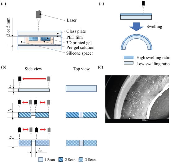
Figure 1.
The process of 3D printing of the ICN gels with the hinge structure. (a) The side cross sectional view of the silicone mold placed on the platform of GelPiPer. Pre-gel solution is sandwiched with the picture-flame shape of 2 mm or 5 mm thickness silicone spacer (outer size: 8 cm × 8 cm, inner size: 7 cm × 7 cm) in the couple of 2 mm thickness glass plates, whose surfaces are covered with 0.5 mm thickness PET films. (b) The molding process of the 3D printed bilayer hydrogels with hinge structure. The scanning numbers can be increased in some areas, and the areas where the scanning numbers are increased will increase in thickness, and polymerization will progress. (c) Deformation of printed modeling objects. The upper figure shows deformation before being placed in water, and the lower figure shows it after being placed in water. Gels with different swelling on the top and bottom layers were printed. (d) The SEM image of the cross section of the dried ICN gels indicates the existence of the bilayer structure. The left side, which seems white, is the UV-exposed side. This part is the upper, thinner layer. The right side is the lower, thicker layer, where the particles of photoinitiator TPO crystals precipitated during the 3D printing process are observed.
2.2. Materials
The structural formula of the ICN gel is shown in Figure 2. In the ICN gel, multiple polymers crosslink each other to form a three-dimensional network. The internal structure is a crosslinked network structure only between different polymers [,,,]. Therefore, the inter-polymer restraints are looser and more spreadable than those of conventional composites, resulting in greater strain in response to tension. In particular, crosslinking flexible and rigid gels can create gels that exhibit even higher ductility. In this study, gels with high strength and ductility and high maximum swelling ratio are preferred because of the tensile and compressive forces that occur when the gel is deformed. In addition, ICN gels was determined to be effective because of their proven track record in 3D gel printing.
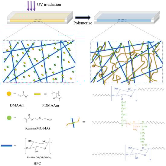
Figure 2.
Schematic illustration of fabrication process of the gradient ICN gels. When the ICN gel solution is scanned with the UV laser from one direction, the UV-exposed side has a higher crosslink density, and the other side has a lower crosslink density.
The material used for ICN gels is the hydrophilic monomer, DMAAm (N,N-dimethylacrylamide), purchased from Tokyo Kasei Kogyo Co (Tokyo, Japan). The polymer, HPC (hydroxypropylcellulose), was purchased from Wako Pure Chemical Industries, Ltd (Osaka, Japan). The crosslinker, KarenzMOI-EG (2-(2-methacryloyloxyethyl)ethyl isocyanate) was purchased from Showa Denko K.K (Tokyo, Japan). The hydrophobic initiator, TPO (diphenyl (2,4,6-trimethylbenzoyl)phosphine oxide) and hydrophilic initiator TPO (lithium phenyl (2,4,6- trimethylbenzoyl)phosphite) were purchased from Tokyo Kasei Co (Tokyo, Japan). The UV absorber AS150 (KAYAPHOR AS150) was purchased from Nippon Kayaku Co (Tokyo, Japan).
To synthesize the ICN gels, DMAAm was added to HPC and stirred for about 1 day to completely dissolve the HPC, then the crosslinking agent was added and stirred for 30 min. Next, purified water was added dropwise to stop the reaction. Finally, photoinitiator, absorbent, and purified water were added and stirred for 30 min. The 3D model was created using the 3D software Fusion360 (Autodesk). The maximum thickness depends on the thickness of the silicone spacer. The adjusted ICN gels were printed using the 3D gel printer under the following printing conditions: scanning speed 20 mm/s, modeling pitch 0.3 mm, spot diameter 0.3 mm, wavelength 405 nm, and UV intensity 10 mW.
3. Factors for Actuation
The composition of gel materials and structures are the key elements of the swelling soft actuators we have developed []. The degree of polymerization and physical properties of hydrogel sheets can be adjusted by changing the material composition. The degree of polymerization and deformation properties can be also adjusted by the structural parameters of the hydrogel sheets such as thickness and the hinge joint. In this experiment, we investigated the influence of the initiator concentration and crosslinker concentration on the material, the thickness of the structure (scanning numbers), and the hinge structure applied to it.
Three evaluation methods were used: swelling ratio measurement, Young’s modulus measurement, and deformation measurement. First, the method of swelling ratio measurement is explained. The test specimens used for the swelling ratio measurement were formed of cylindrical gels of 16 mm in diameter with different degrees of polymerization, with different numbers of laser scans. The gel sheets were immersed in water and weighed at regular intervals. The swelling ratio was then calculated from the ratio of the weight immediately after formation to the weight after swelling.
For the swelling ratio measurement, three samples each were measured and the average was calculated. The swelling ratio was determined by the following equation:
Here, , , and refer to the weight of gel per expansion time, weight of gel before swelling, and swelling ratio, respectively. Silicon spacers of 2 mm and 5 mm thicknesses were used to fill the solution used to create the modeling objects with the 3D gel printer.
Young’s modulus of the ICN gels was calculated from the compression test. The samples used for the test were cylindrical gels of 16 mm in diameter with different scans. The thickness of the sample depended on the thickness of the silicone spacer used. The tabletop material testing machine (Orientec Corporation, STA-1150) was used for compression testing. The speed of the compression test was set at 1 mm/min, and each sample was measured three times. Based on the measured results, Young’s modulus was calculated from the gradient up to a strain of 0.1, and the average value of three times each was obtained.
An important parameter for producing the desired 4D structure is the bending angle, , between the hydrogel sheet and the glass substrate at the time of deformation due to swelling behavior (Figure 3). The silicone spacer with a thickness of 5 mm was used to form a rectangular specimen with a width of 5 mm and a length of 22 mm. The thickness of the specimen depended on the scanning numbers and the initiator and crosslinker concentrations. A part of the specimen was glued to the bottom of the container so as not to interfere with the bending motion before the container was filled with water. The angle was determined from the images taken by a camera using image analysis software (ImageJ).
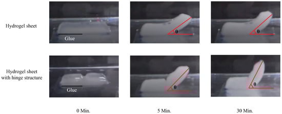
Figure 3.
The photos of 3D printed bilayer gels of the hydrogel sheet without/with the hinge structure during swelling process. The left half side of all the gels is bonded on glass plate. The right half side in not bonded and then can lift up in the swelling process. The red angles indicate the degree of bending deformation.
3.1. Materials Composition
3.1.1. Initiator Concentration
First, the effect of swelling ratio at different initiator concentrations was investigated. The specimens used to measure the swelling ratio were fixed to one and three laser scans, and two types of cylindrical gels (Table 1) with different degrees of polymerization were formed. In this experiment, the effect of the concentration of the photoinitiator TPO on the swelling ratio was investigated. The crosslinker concentration was fixed at 0.02 (mol/L), and cylindrical gels were formed with three solutions in which the initiator concentration was 0.005 (mol/L), 0.01 (mol/L), and 0.02 (mol/L) relative to the monomer. The silicon spacer with 2 mm thickness was used to fill the solutions. When the silicon spacer is 2 mm thick, it is possible to form a gel with no difference in the degree of polymerization between the top and bottom layers of the object because the hardening area that can be formed by one laser scan is shorter than the amount of laser light transmitted. Table 1 shows that at a TPO addition level of 0.01 (mol/L), the white area gradually appeared after three laser scans cycles, and at 0.02 (mol/L), the area turned completely white. Figure 4a also shows that for the initiator concentration of 0.005 (mol/L), the swelling ratio was higher with fewer laser scanning times, whereas for initiator concentrations of 0.01 (mol/L) and 0.02 (mol/L), the swelling ratio was higher with more laser scanning times. This indicates that the TPO crystals play a role in raising the swelling ratio. In addition, the results showed that initiator concentration of 0.01 (mol/L) resulted in highest swelling ratio of three initiator concentration after one and three scans.

Table 1.
Photographs of 3D printed one-layer gels in the various concentrations of the initiator TPO and in the one or three scanning numbers of UV irradiation in 3D printing.
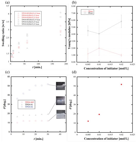
Figure 4.
(a) The swelling ratio measurement as a function of time, in the various concentrations of the initiator TPO and in the one or three scanning numbers of UV irradiation in 3D printing. (b) The Young’s modulus measurement as a function of the concentration of the initiator TPO in the one or three scanning numbers of UV irradiation in 3D printing. (c) The bending angle with the various concentrations of the initiator TPO. The inset photographs indicate the final states of deformation. (d) The bending angle vs. the concentration of the initiator TPO.
Next, the Young’s modulus of cylindrical gels at different initiator concentrations (0.005, 0.01, and 0.02 mol/L) was examined from compression tests. The samples to be measured were prepared immediately after printing one and three times of laser scanning. Any correlation of Young’s modulus with the initiator concentrations was not observed, as shown in Figure 4b, whereas the Young’s modulus increased with increasing laser scanning time.
Finally, deformation measurements were performed. The hydrogel sheets were 3D printed with three scans and with three different TPO concentrations: 0.005 (mol/L), 0.01 (mol/L), and 0.02 (mol/L). The results in Figure 4c,d show that increasing the initiator concentration increased the bending angle. In addition, the initiator concentration at 0.005 (mol/L) and 0.01 (mol/L) did not deform much, whereas the initiator concentration at 0.02 (mol/L) deformed more than twice as much, indicating that the initiator concentration has a significant effect on the deformation.
3.1.2. Crosslinker Concentration
First, we investigated the effect of different crosslinker concentrations on the ratio of swelling. The specimens used to measure the swelling ratio were fixed to one and three laser scans, and two types of cylindrical gels with different degrees of polymerization were formed with the silicone spacer thickness of 2 mm. In this experiment, the effect of crosslinker concentration on the swelling ratio was investigated. The initiator concentration was fixed at 0.02 (mol/L), and three crosslinker concentrations of 0.02 (mol/L), 0.1 (mol/L), and 0.2 (mol/L) were used with respect to the monomer to form cylindrical gels and measure swelling ratio. The samples were transparent after one scan and whitened after three scans with 0.02 (mol/L) and 0.1 (mol/L) of crosslinker and slightly whitened after one scan with 0.2 (mol/L) of crosslinker. Figure 5a shows that the swelling ratio was increasing with decreasing crosslinker concentrations. This indicates that the swelling ratio is higher when the crosslinking density is lower. In addition, the swelling ratio is higher for three scans than for one scan for any crosslinker concentration.
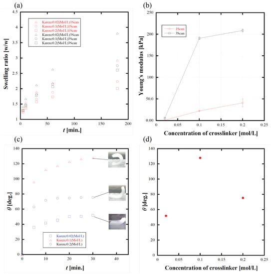
Figure 5.
(a) The swelling ratio measurement as a function of time, in the various crosslinker concentrations and in the one or three scanning numbers of UV irradiation in 3D printing. (b) Young’s modulus measurement as a function of the crosslinker concentration, in the one or three scanning numbers of UV irradiation in 3D printing. (c) The degree of deformation measurement as a function of time in the various crosslinker concentrations. The inset photographs indicate the final states of deformation. (d) The bending angle vs. the concentration of the crosslinker Karenz MOI-EG.
Next, the effect of Young’s modulus at different crosslinker concentrations was investigated. The cylindrical gels were printed for the swelling ratio measurement. From the results in Figure 5b, it can be seen that Young’s modulus is higher for three scans than for one scan. Young’s modulus increases with increasing crosslinker concentration. This indicates that Young’s modulus can be controllable by the crosslinker concentration.
Finally, deformation measurements were performed. All scanning numbers were fixed at three times. The results in Figure 5c,d show that the bending angle increased with increasing crosslinker concentration. It was also found that 0.1 (mol/L) of crosslinker addition caused the most deformation, whereas 0.02 (mol/L) caused the least deformation. From these results, it is considered that for three scans, the difference between the UV-exposed side and other side was the largest at a crosslinker concentration of 0.1 (mol/L). At 0.2 (mol/L), the polymerization was too strong, resulting in a low difference in the degree of polymerization between the top and bottom layers.
3.2. Structure
Thickness and Hinge Structure
First, the effect of swelling ratio on the thickness was investigated. The number of laser scans was varied from one, two, three, and five times to form a cylindrical gel structure. For the materials, the initiator concentration and crosslinker concentration was fixed at 0.02 (mol/L). The thickness of the silicon spacer was set to 5 mm. The transparent specimens of 3 mm and 4 mm thickness were made after one and two scans, respectively. In the case of three and five scans, the 5 mm thick gel was formed, including white and transparent layers. The white layer in five scans was thicker than in three scans. Figure 6a shows that the swelling ratio decreased with increasing scan number. However, the swelling ratio in five scans was higher than in three scans. From these results, it can be predicted that the swelling ratio is higher due to increasing white layer.
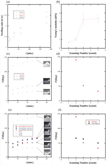
Figure 6.
(a) The swelling ratio measurement as a function of time, in the one, two, three, and five scanning numbers of UV irradiation in 3D printing. (b) Young’s modulus measurement as a function of the scanning number of UV irradiation in 3D printing. (c) The bending angle as a function of time, in the various scanning numbers, without hinge structure. The inset photographs indicate the final states of deformation. (d) The bending angle as a function of the scanning number, without hinge structure. (e) The bending angle as a function of time, in the various scanning numbers, with/without hinge structure. The inset photographs indicate the final states of deformation. (f) The bending angle as a function of the scanning number, with/without hinge structure.
Next, the effect of Young’s modulus was examined when the thickness was changed. The sample used was fixed at the silicone spacer thickness of 5 mm, and the same samples as for the swelling ratio measurement was prepared and measured. The results in Figure 6b show that Young’s modulus increases as the scanning numbers increases. Young’s modulus increased about three times when the scanning numbers increased from two to three, and Young’s modulus was close between three and five scans. From this result, it can be predicted that the Young’s modulus reaches its maximum around five scans under these conditions.
Finally, deformation measurements were performed. The specimens were scanned two, three, and five times. The results in Figure 6c,d show that the bending angle became lower as the scanning numbers increased. Comparing the three and five scans, the bending angle is larger in the three scans, indicating that the difference in crosslink density between the UV-exposed side and the other side and the ratio of each is important.
Based on the deformation measurement results, we attempted a deformation measurement of a hinge structure. This hinge has a structure with a concave part 2 mm length and 3 mm thick between convex parts 10 mm length and 5 mm thick (Figure 1b). The number of scans of the convex parts was changed to two three, and five times, whereas the number of scans of the concave part was fixed at one time. In addition, 10 mm of the convex part was glued, whereas the opposite convex part and the concave part between them were left free. Figure 6e,f show that the hinge structure was less deformed than the hydrogel sheet after two scans. This result is thought to be due to the fact that the concave part of the hinge structure was deformed roundly before the convex part, so that the bonded convex part and the free convex part collided and could not be deformed any further. It was also found that the hinge structure works to increase the bending angle when the material not deformed to 90° when it was hydrogel sheet, as in the case of three or five scan times. This result is thought to be because the concave part deforms before the convex part, thus combining the deformation of the convex part with the deformation of the concave part.
3.3. Important Factors
Table 2 summarizes the factors important for 4D printing from the above results. The initiator concentration is probably the most important factor for deformation, as low initiator concentration significantly reduces deformation. The crosslinker concentration increases the hardness of the material by a factor of nearly 40, which may help the material retain its shape when it is removed from the water. Adjusting the crosslinker concentration enables a wider range of deformation adjustment than changing the initiator concentration. Without the changing material compositions, the bending angle can be controlled by the thickness of the gel sheet that can be changed with the scanning number during 4D printing. In addition, the hinge structure can be applied to origami structures such as boxes because the deformation can be limited to 90° by the deformation irregularities.
Table 2.
Summary of important factors for 4D printing.
4. Application of Hinge Structure
Various shapes can be created by applying the above hydrogel sheets with/without a hinge structure. For example, in Figure 7a, a model of a jellyfish was created by rounding the entire layer using curvature drawing when the hinge structure is not included. This modeling is deformed only by the degree of overlapping gradient between the top and bottom layer. In Figure 7b, the hinge structure is created by using the concave part as the axis of deformation, and the hinge structure is used as the joint when the cube is unfolded. In Figure 7c, the deformation pattern was adjusted by changing the angle of the hinge structure, as shown in Figure 8. By changing the angle and shape of the hinge structure in this way, the type of deformation can also be increased. In Figure 7d, the method to deform the legs downward, the tail upward, and the scissors in the horizontal direction at the same time is based on separate printing for each direction to be deformed, as shown in Figure 9. By creating the body and tail at the beginning and sculpting the legs to be deformed in the opposite direction by flipping the container filled with solution, mountain folds and valley folds were the legs to be deformed in the opposite direction are formed by turning the container filled with the solution upside down. As for the scissors, the hinge structure was added to the triangle as shown in the red frame in Figure 9, which made it possible.
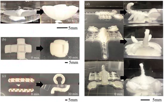
Figure 7.
The before and after photographs of 4D printing of hydrogels controlled by hinge structure and spatially gradient swelling at 0 min and 30 min. (a) Jellyfish model (without hinge structure). (b) Cubic origami. (c) Warm models with two different hinge structures. (d) Scorpion model.
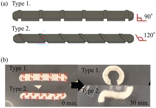
Figure 8.
The 4D printing of worm models with two different hinge structures. (a) The design of the two different hinge structures. Type 1 is a transverse hinge, whose angle between the hinge direction and the longitudinal direction of the worm is 90 degrees. Type 2 is a tilted hinge, whose angle between the hinge direction and the longitudinal direction of the worm is 120 degrees. (b) The before and after photographs of the two different worms. Type 1 is the transverse hinge bent until it came around. Type 2 is the tilted hinge twisted until it formed an S shape.
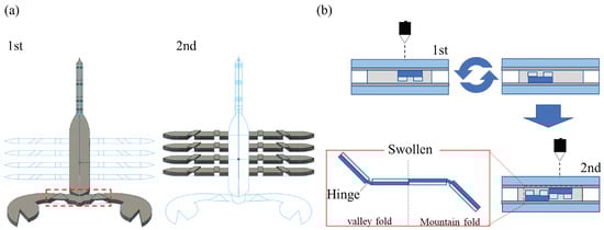
Figure 9.
The 4D printing of the scorpion model. (a) The two-step method of 3D printing of the scorpion. In the first step, the body and scissor parts are 3D printed. In the second step, the previously printed body and scissors are flipped over and then the eight legs are 3D printed. (b) The actual 3D printing process. After the first step of 3D printing, the silicone mold is turned over and the part to be made in the second step is 3D printed from the opposite side. This enables the 4D printing of both valley and mountain folds as in origami.
5. Simulation
To better understand the deformation of bilayer gels and predict the bending angle for design purposes, we developed finite element (FE) swelling models of bilayer gels using Abaqus (SIMULIA, Dassault System, MA). Two FE models with different layered structures were built. One has two identical layers with dimensions of 22 mm (L) × 5 mm (W) × 2.5 mm (H) for each layer. The other has the same geometry with the hinge at the middle, as shown in Figure 2. To simulate the gel swelling phenomenon, coupled-thermal displacement analysis was performed with thermal expansion coefficients as given in Figure 4a with TPO addition of 0.02 mol/L. The bilayered gels were bonded together using “tie” constraints, and half of the bottom layer was constrained to not have deformation in the Z—axis to simulate the boundary condition used in experiments. The FE model was meshed with 20-node tetrahedron elements (C3D20T) with a global mesh seed of 0.5 mm. As the gel experiences large deformation, geometric non-linearity was considered in the simulation.
Simulation results are shown in Figure 10. The bending angle was calculated as shown in Figure 10a with the dashed lines. The bending deformation experienced in different time periods is shown in Figure 10c. The largest bending angle is approximately 62, and the bending deformation is converging along with the time increase. Comparing with the experimental results shown in Figure 7 and Figure 8, FE simulation resulted in less bending deformation, especially in the model with the hinge structure. One possible reason might be the complex swell property during the scan, and a swelling gradient may exist. Nevertheless, we can simulate and predict gel bending deformation induced by swelling using FE simulation, and it could help the design of complex bending geometry.
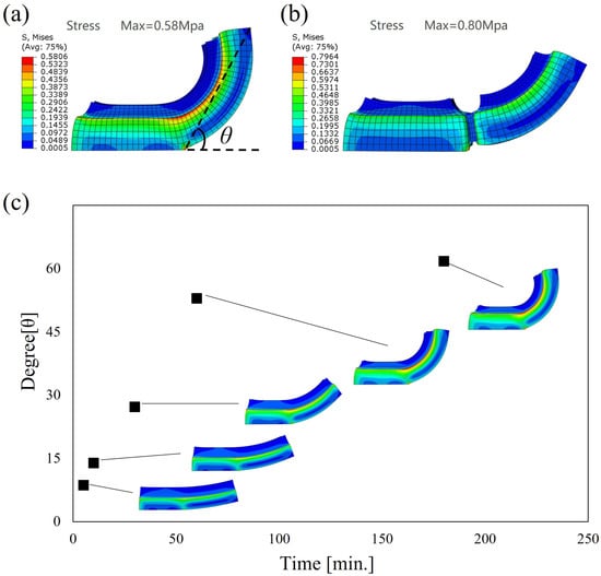
Figure 10.
FE simulation results of: (a) the two identical layer model, (b) the model with a hinge structure, and (c) the bending deformation in different time periods.
6. Conclusions
In this work, we developed self-folding 3D printed ICN gels that resemble a bilayer structure using SLA techniques. The UV-exposed side has the higher crosslinking density of the ICN gels than the other side because of higher concentration of free radicals on the UV-exposed side. Thus, the thickness and the crosslinking density gradient of the 3D gels along the thickness direction were adjusted by the material composition and the laser scan intensity. The existence of and crosslinking density gradient of the ICN gels were confirmed by SEM. When immersed into water, the originally flat sheet of the ICN gels curved up toward the UV-exposed side along the lateral axis into a U structure due to the high swelling ratio of the UV-exposed side. By controlling the composition of the ICN gels, the UV irradiance, and the shape (hinge structure), the bending angle can be programmed. In addition, FEM simulation for bending phenomena provides insights that the bending shape can be designed in cyberspace.
Author Contributions
Conceptualization, M.K. (Masanari Kameoka), Y.W., M.N.I.S. and H.F.; methodology, M.K. (Masanari Kameoka), Y.W., M.N.I.S. and M.K. (Masaru Kawakami); simulation, S.Z. and Z.W.; validation, Y.W., M.N.I.S., M.K. (Masaru Kawakami), H.F., S.Z. and Z.W.; investigation, M.K. (Masanari Kameoka), Y.W., M.N.I.S., M.K. (Masaru Kawakami), J.O., A.K., H.F., S.Z., S.H. and Z.W.; data curation, M.K. (Masanari Kameoka) and S.Z.; writing—original draft preparation, M.K. (Masanari Kameoka); writing—review and editing, Y.W., M.K. (Masaru Kawakami) and H.F.; visualization, M.K. (Masanari Kameoka), Y.W. and S.Z.; funding acquisition H.F., S.H. and Z.W.; supervision S.H.; project administration H.F. All authors have read and agreed to the published version of the manuscript.
Funding
This work was supported in part by JSPS KAKENHI Grant Number JP18H05471, JP19H01122, JP21H04936, JP21K14040, JP22K17972, JST-OPERA Program Grant Number JPMJOP1844, Moonshot Agriculture, Forestry and Fisheries Research and Development Program (MS508, Grant Number JPJ009237) and the Cabinet Office (CAO), Cross-ministerial Strategic Innovation Promotion Program (SIP), “An intelligent knowledge processing infrastructure, integrating physical and virtual domains”, ”Intensive Support for Young Promising Researchers”(funding agency: NEDO).
Data Availability Statement
Not applicable.
Conflicts of Interest
The authors declare no conflict of interest.
References
- Tibbits, S. 4D Printing: Multi-Material Shape Change. Archit. Des. 2014, 84, 116–121. [Google Scholar] [CrossRef]
- Tibbits, S.; McKnelly, C.; Olguin, C.; Dikovsky, D.; Hirsch, S. 4D printing and universal transformation. In Proceedings of the 34th Annual Conference of the Association for Computer Aided Design in Architecture (ACADIA 2014 Design Agency), Los Angeles, CA, USA, 23–25 October 2014; pp. 539–548. [Google Scholar]
- More Talent Literacy; Less Talent Management. Clearing the Way for Pivotal 21st-Century Innovation. Gift. Talent. 21st Century 2016, 10, 163–179. [Google Scholar]
- Ge1, Q.; Qi, H.J.; Dunn, M.L. Active materials by four-dimension printing. Appl. Phys. Lett. 2013, 103, 131901. [Google Scholar]
- Huang, L.; Jiang, R.; Wu, J.; Song, J.; Bai, H.; Li, B.; Zhao, Q.; Xie, T. Ultrafast digital printing toward 4D shape changing materials. Adv. Mater. 2017, 29, 1605390. [Google Scholar] [CrossRef]
- Kuang, X.; Roach, D.J.; Wu, J.; Hamel, C.M.; Ding, Z.; Wang, T.; Dunn, M.L.; Qi, H.J. Advances in 4D printing: Materials and applications. Adv. Funct. Mater. 2019, 29, 1805290. [Google Scholar] [CrossRef]
- Pei, E. 4D Printing: Dawn of an emerging technology cycle. Assem. Autom. 2014, 34, 310–314. [Google Scholar] [CrossRef]
- Khoo, Z.X.; Teoh, J.E.M.; Liu, Y.; Chua, C.K.; Yang, S.; An, J.; Leong, K.F.; Yeong, W.Y. 3D printing of smart materials: A review on recent progresses in 4D printing. Virtual Phys. Prototyp. 2015, 10, 103–122. [Google Scholar] [CrossRef]
- Raviv, D.; Zhao, W.; McKnelly, C.; Papadopoulou, A.; Kadambi, A.; Shi, B.; Hirsch, S.; Dikovsky, D.; Zyracki, M.; Olguin, C.; et al. Active printed materials for complex self-evolving deformations. Sci. Rep. 2014, 4, 7422. [Google Scholar] [CrossRef]
- Mao, Y.; Yu, K.; Isakov, M.S.; Wu, J.; Dunn, M.L.; Qi, H.J. Sequential Self-Folding Structures by 3D Printed Digital Shape Memory Polymers. Sci. Rep. 2016, 7, 163–179. [Google Scholar] [CrossRef]
- Kai, Y.; Dunn, M.L.; Qi, H.J. Digital manufacture of shape changing components. Extrem. Mech. Lett. 2015, 4, 9–17. [Google Scholar]
- Wu, J.; Yuan, C.; Ding, Z.; Isakov, M.; Mao, Y.; Wang, T.; Dunn, M.L.; Qi, H.J. Multi-shape active composites by 3D printing of digital shape memory polymers. Sci. Rep. 2016, 6, 24224. [Google Scholar] [CrossRef]
- Kuksenok, O.; Balazs, A.C. Stimuli-responsive behavior of composites integrating thermo-responsive gels with photo-responsive fibers. Mater. Horizons 2016, 3, 53–62. [Google Scholar] [CrossRef]
- Bakarich, S.E.; Gorkin, R., III; Panhuis, M.I.H.; Spinks, G.M. 4D printing with mechanically robust, thermally actuating hydrogels. Macromol. Rapid Commun. 2015, 36, 1211–1217. [Google Scholar] [CrossRef]
- Zhou, J.; Sheiko, S.S. Reversible shape-shifting in polymeric materials. Gift. Talent. 21st Century 2016, 54, 1365–1380. [Google Scholar] [CrossRef]
- Jeong, H.Y.; Woo, B.H.; Kim, N.; Jun, Y.C. Multicolor 4D printing of shape-memory polymers for light-induced selective heating and remote actuation. Sci. Rep. 2020, 10, 6258. [Google Scholar] [CrossRef]
- Lai, J.; Ye, X.; Liu, J.; Wang, C.; Li, J.; Wang, X.; Ma, M.; Wang, M. 4D printing of highly printable and shape morphing hydrogels composed of alginate and methylcellulose. Mater. Des. 2021, 205, 109699. [Google Scholar] [CrossRef]
- Rahmatabadi, D.; Aberoumand, M.; Soltanmohammadi, K.; Soleyman, E.; Ghasemi, I.; Baniassadi, M.; Abrinia, K.; Bodaghi, M. 4D Printing-Encapsulated Polycaprolactone–Thermoplastic Polyurethane with High Shape Memory Performances. Adv. Eng. Mater. 2022, 2201309. [Google Scholar] [CrossRef]
- Bodaghi, M.; Damanpack, A.R.; Liao, W.H. Adaptive metamaterials by functionally graded 4D printing. Mater. Des. 2017, 135, 26–36. [Google Scholar] [CrossRef]
- Song, Z.; Ren, L.; Zhao, C.; Liu, H.; Yu, Z.; Liu, Q.; Nonuniform, L.R.B. Dual-Stimuli Self-Morphing Enabled by Gradient Four-Dimensional Printing. ACS Appl. Mater. Interfaces 2020, 12, 6351–6361. [Google Scholar] [CrossRef]
- Ge, Q.; Sakhaei, A.H.; Lee, H.; Dunn, C.K.; Fang, N.X.; Dunn, M.L. Multimaterial 4D printing with tailorable shape memory polymers. Sci. Rep. 2016, 6, 31110. [Google Scholar] [CrossRef]
- Shiblee, M.N.I.; Ahmed, K.; Kawakami, M.; Furukawa, H. 4D Printing of Shape-Memory Hydrogels for Soft-Robotic Functions. Adv. Mater. Technol. 2019, 4, 1900071. [Google Scholar] [CrossRef]
- Shiblee, M.N.I.; Ahmed, K.; Khosl, A.; Kawakami, M.; Furukawa, H. 3D printing of shape memory hydrogels with tunable mechanical properties. Soft Matter 2018, 14, 7809–7817. [Google Scholar] [CrossRef]
- Rahmatabadi, D.; Aberoumand, M.; Soltanmohammadi, K.; Soleyman, E.; Ghasemi, I.; Baniassadi, M.; Abrinia, K.; Zolfagharian, A.; Bodaghi, M.; Baghani, M. A New Strategy for Achieving Shape Memory Effects in 4D Printed Two-Layer Composite Structures. Polymers 2022, 24, 5446. [Google Scholar] [CrossRef] [PubMed]
- Muroi, H.; Hidema, R.; Gong, J.; Furukawa, H. Development of optical 3D gel printer for fabricating free-form soft & wet industrial materials and evaluation of printed double-network gels. J. Solid Mech. Mater. Eng. 2013, 7, 163–168. [Google Scholar]
- Ota, T.; Saito, A.; Tase, T.; Sato, K.; Tanaka, M.; Yoshida, K.; Takamatsu, K.; Kawakami, M.; Furukawa, H. 3D Printing of Tough Gels Having Tunable Elastic Modulus from the Same Pre-Gel Solution. Macromol. Chem. Phys. 2019, 220, 1800498. [Google Scholar] [CrossRef]
- Okumura, Y.; Ito, K. The polyrotaxane gel: A topological gel by figure-of-eight cross-links. Adv. Mater. 2001, 13, 485–487. [Google Scholar] [CrossRef]
- Haraguchi, K.; Takehisa, T. TNanocomposite Hydrogels: A Unique Organic–Inorganic Network Structure with Extraordinary Mechanical, Optical, and Swelling/De-swelling Properties. Adv. Mater. 2002, 14, 1120–1124. [Google Scholar] [CrossRef]
- Gong, J.P.; Katsuyama, Y.; Kurokawa, T.; Osada, Y. Double-Network Hydrogels with Extremely High Mechanical Strength. Adv. Mater. 2003, 15, 1155–1158. [Google Scholar] [CrossRef]
- Yin, J.; Fan, W.; Xu, Z.; Duan, J.; Xia, Y.; Nie, Z.; Sui, K. Precisely defining local gradients of stimuli-responsive hydrogels for complex 2D-to-4D shape evolutions. Small 2022, 18, 2104440. [Google Scholar] [CrossRef]
- Kuksenok, O.; Yashin, V.V.; Kinoshita, M.; Sakai, T.; Yoshidab, R.; Balazs, A.C. Exploiting gradients in cross-link density to control the bending and self-propelled motion of active gels. J. Mater. Chem. 2011, 21, 8360–8371. [Google Scholar] [CrossRef]
- Fan, W.; Shan, C.; Guo, H.; Sang, J.; Wang, R.; Zheng, R.; Sui, K.; Nie, Z. Dual-gradient enabled ultrafast biomimetic snapping of hydrogel materials. Sci. Adv. 2019, 5, eaav7174. [Google Scholar] [CrossRef]
- Ge1, Q.; Dunn, C.K.; Qi, H.J.; Dunn, M.L. Active origami by 4D printing. SMart Mater. Struct. 2014, 23, 094007. [Google Scholar]
- Chalapat, K.; Chekurov, N.; Jiang, H.; Li, J.; Parviz, B.; Paraoanu, G.S. Self-Organized origami structures via Ion-Induced plastic strain. Adv. Mater. 2013, 25, 91–95. [Google Scholar] [CrossRef]
- Liu, Y.; Zhang, W.; Zhang, F.; Lan, X.; Leng, J.; Liu, S.; Jia, X.; Cotton, C.; Sun, B.; Bohong, G. Shape memory behavior and recovery force of 4D printed laminated Miura-origami structures subjected to compressive loading. Compos. Part Eng. 2018, 153, 233–242. [Google Scholar] [CrossRef]
- Jamal, M.; Kadam, S.S.; Xiao, R.; Jivan, F.; Onn, T.M.; Fernandes, R.; Nguyen, T.D.; Gracias, D.H. Bio-origami hydrogel scaffolds composed of photocrosslinked PEG bilayers. Adv. Healthc. Mater. 2015, 5, 1–12. [Google Scholar] [CrossRef]
- Takada, G.; Hidema, R.; Furukawa, H. Ultrahigh Ductile Gels Having Inter-Crosslinking Network (ICN) Structure. e-J. Surf. Sci. Nanotechnol. 2012, 10, 346–350. [Google Scholar] [CrossRef]
- Takada, G.; Hidema, R.; Furukawa, H. Ultrahigh ductile gels developed by inter cross-linking network (ICN). J. Solid Mech. Mater. Eng. 2012, 6, 169–177. [Google Scholar] [CrossRef]
- Watanabe, Y.; Inoue, S.; Saito, A.; Kawakawami, M.; Furukawa, H. 3D printable inter cross-linking network (ICN) gels for reversible transparency control with water content. Microsyst. Technol. 2022, 28, 167–171. [Google Scholar] [CrossRef]
- Yamazaki, Y.; Saito, A.; Yamazaki, M.; Watanabe, Y.; Shiblee, M.N.I.; Khosla, A.; Ogawa, J.; Kawakami, M.; Nango, J.; Furukawa, H. TheSimultaneous 3D Printing of White and Transparent Gels for Medical Models. ECS Trans. 2020, 98, 47. [Google Scholar] [CrossRef]
- Takishima, Y.; Yoshida, K.; Khosla, A.; Kawakami, M.; Furukawa, H. Fully 3D-printed hydrogel actuator for jellyfish soft robots. ECS J. Solid State Sci. Technol. 2021, 10, 037002. [Google Scholar] [CrossRef]


Disclaimer/Publisher’s Note: The statements, opinions and data contained in all publications are solely those of the individual author(s) and contributor(s) and not of MDPI and/or the editor(s). MDPI and/or the editor(s) disclaim responsibility for any injury to people or property resulting from any ideas, methods, instructions or products referred to in the content. |
© 2023 by the authors. Licensee MDPI, Basel, Switzerland. This article is an open access article distributed under the terms and conditions of the Creative Commons Attribution (CC BY) license (https://creativecommons.org/licenses/by/4.0/).