Article

Coordinated Feedback–Feedforward Control for Coupled Seat–Suspension Dynamics: A Ride Comfort Enhancement Strategy for In-Wheel-Motor Electric Vehicles

by
Magdy Abdullah Eissa
1,2,* and
Pingen Chen
3
1
Department of Engineering and Engineering Technology, University of Wisconsin–River Falls, River Falls, WI 54022, USA
2
Department of Mechanical Engineering, Faculty of Engineering, Capital University, Cairo 11795, Egypt
3
Department of Mechanical and Aerospace Engineering, The University of Tennessee, Knoxville, Knoxville, TN 37996, USA
*
Author to whom correspondence should be addressed.
World Electr. Veh. J. 2026, 17(7), 379; https://doi.org/10.3390/wevj17070379
Submission received: 11 May 2026 / Revised: 10 July 2026 / Accepted: 11 July 2026 / Published: 22 July 2026
(This article belongs to the Section Vehicle Control and Management)

Abstract

Electric vehicles equipped with in-wheel motors provide packaging, controllability, and drivetrain-simplification advantages; however, the increase in wheel-side unsprung mass can intensify vibration transmission to the chassis, seat, and occupant. This paper presents a coordinated active seat and active suspension control strategy for an integrated 8-DOF quarter-car model that includes an in-wheel motor, an active seat suspension, and a 4-DOF seated driver body model. The proposed controller combines a Harmony Search (HS)-optimized proportional–integral–derivative (PID) feedback baseline with a repeatable-disturbance feedforward compensation term. The HS-PID loop provides baseline transient attenuation, while the feedforward term compensates the repeatable component of the bump-induced disturbance transmitted through the coupled seat–vehicle system. The controller is evaluated against passive suspension, active-seat-only control, active-vehicle-suspension-only control, and an HS-PID baseline under repeated bump/shock excitation. The results show that coordinated actuation reduces occupant displacement and acceleration responses relative to the benchmark cases. The discussion explains the active-seat-only peak-acceleration amplification, the different magnitudes of displacement and acceleration improvements, and the practical implications of suspension stroke and actuator-force limits. The reported conclusions are therefore confined to the repeated bump/shock condition considered in this numerical study; broader ride-comfort generalization requires standardized whole-body vibration metrics, random-road validation, speed variation, parametric uncertainty analysis, and drivetrain energy evaluation.

1. Introduction

Electric vehicle (EV) development has accelerated because of the need to reduce transportation-related energy consumption and emissions [1,2]. Advanced EV propulsion architectures have become important for improving packaging efficiency, controllability, and vehicle-dynamics performance [3,4].
Among EV propulsion layouts, in-wheel-motor (IWM) systems are attractive because they eliminate conventional driveline components, enable independent wheel-torque control, and support direct integration with vehicle stability and ride-control systems [5,6]. However, locating the motor at the wheel increases the effective unsprung mass, which can modify wheel-hop dynamics, increase tire-force variation, and degrade both road holding and ride comfort [5,6,7]. Therefore, vibration suppression remains a central design requirement for practical IWM-EV implementation [8,9].
Vehicle suspension control is governed by a trade-off between ride comfort and road holding. A wide range of active and semi-active suspension controllers has been studied, including PID-based, robust, fuzzy, model-predictive, and learning-based methods [6,7,9]. Feedback controllers provide strong baseline attenuation for broadband transient disturbances, but they do not directly exploit repeatability when the vehicle encounters the same finite road feature multiple times. A feedforward compensation term based on repeatable disturbance information can therefore complement feedback control for repeated bump scenarios. This idea is rooted in the classical concept of iterative learning control [10], in which control actions can be improved over repeated finite-duration tasks. In this work, the iterative-learning concept is used only as a design motivation for the feedforward compensation term; the proposed controller is not presented as a demonstrated multi-iteration ILC implementation.
The seated occupant experiences vibration after it has propagated through the tire, suspension, chassis, seat frame, and cushion. Biodynamic driver models allow head, torso, and thigh responses to be evaluated directly [11,12,13]. This motivates an integrated vehicle–seat–driver formulation in which main-suspension and seat-suspension actuation are coordinated rather than controlled independently.
The specific research gap addressed in this study is the limited investigation of coordinated feedback–feedforward control for an integrated IWM-EV, active-seat, and seated-driver model. Previous work has often examined vehicle or seat suspension separately, whereas the present study evaluates their coordinated action in a coupled model.
Recent developments in higher-order intelligent control suggest promising extensions for adaptive vibration suppression. Type-3 adaptive neuro-fuzzy inference systems have been proposed for robust learning and uncertainty compensation under noisy conditions [14]. Such structures could be integrated in future seat–suspension controllers for online gain adaptation.
The main contributions are as follows. First, an 8-DOF IWM-seat-driver model is used to evaluate ride comfort at the occupant level. Second, main-suspension and seat-suspension actuation are coordinated. Third, an HS-PID feedback baseline is combined with repeatable feedforward compensation. Fourth, the results are interpreted physically, and the claims are limited to the repeated bump/shock excitation tested in this study.

2. System Description and Problem Formulation

2.1. Integrated Vehicle–Seat–Driver Model

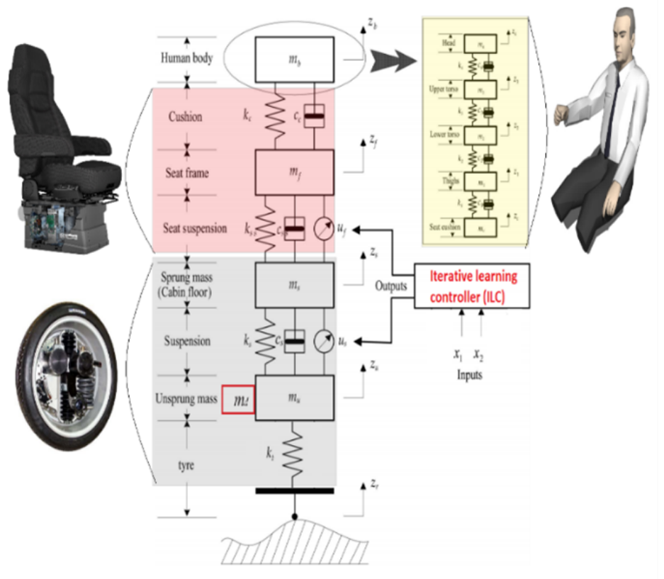
An integrated vertical dynamic model is considered, as illustrated in Figure 1. The model combines a quarter-car IWM-EV suspension, an active seat suspension, and a 4-DOF seated driver model.
The vertical equations of motion are
( m u + m d ) z ¨ u = k t ( z u z r ) c t ( z ˙ u z ˙ r ) + k s ( z s z u ) + c s ( z ˙ s z ˙ u ) + u s ,
m s z ¨ s = k s ( z s z u ) c s ( z ˙ s z ˙ u ) + k s s ( z f z s ) + c s s ( z ˙ f z ˙ s ) u s + u f ,
m f z ¨ f = k s s ( z f z s ) c s s ( z ˙ f z ˙ s ) + k c ( z c z f ) + c c ( z ˙ c z ˙ f ) u f ,
m c z ¨ c = k c ( z c z f ) c c ( z ˙ c z ˙ f ) + k 1 ( z 1 z c ) + c 1 ( z ˙ 1 z ˙ c ) ,
m i z ¨ i = k i ( z i z i 1 ) c i ( z ˙ i z ˙ i 1 ) + k i + 1 ( z i + 1 z i ) + c i + 1 ( z ˙ i + 1 z ˙ i ) , i = 1 , 2 , 3 ,
m 4 z ¨ 4 = k 4 ( z 4 z 3 ) c 4 ( z ˙ 4 z ˙ 3 ) .
Here, m s , m u , m d , m f , m c , and m 1 m 4 are the sprung, unsprung, IWM, seat-frame, cushion, and driver-body masses. The control forces u s and u f are generated by the active vehicle- and seat-suspension actuators.

2.2. State-Space Representation

x ˙ = A x + B u u ¯ + B w w , y = C s x ,
where w = z ˙ r and u ¯ = [ u ¯ s , u ¯ f ] T is the saturated actuator vector. The output matrix C s selects comfort-related occupant-body and suspension-deflection variables for feedback regulation. The desired regulated output is y d = 0 .
u ¯ i = sat ( u i ) = U lim , i , u i < U lim , i , u i , | u i | U lim , i , U lim , i , u i > U lim , i , i { s , f } .

2.3. Model Parameters

Table 1 lists the fixed mechanical plant parameters. Active behavior is produced by u s and u f . The tire damping c t = 0 represents the standard quarter-car simplification.

3. Controller Design

The controller is formulated as an HS-PID + Feedforward scheme. The HS-PID component provides the feedback baseline, while the feedforward component compensates the repeatable part of the bump-induced disturbance. The actuator command is
u ( t ) = K u 1 ( t ) + u 2 ( t ) ,
where K is the actuator-allocation matrix, u 1 ( t ) is the HS-PID feedback signal, and u 2 ( t ) is the feedforward compensation signal. The feedback signal is defined by
u 1 ( t ) = k p e ( t ) + k d e ˙ ( t ) + k i 0 t e ( τ ) d τ , e ( t ) = y ( t ) .
For a repeated finite road segment, the disturbance is decomposed as w ( t ) = w r ( t ) + w n ( t ) , where w r ( t ) is the repeatable component and w n ( t ) is bounded nonrepeatable variation. The feedforward term u 2 ( t ) compensates w r ( t ) , while the HS-PID loop handles both components in real time.

Simulation Setup and Reproducibility Parameters

Table 2 summarizes the numerical, road-input, and controller parameters used in the simulations. These parameters define the regulated output, actuator limits, road excitation, solver settings, and feedforward formulation required for reproducibility.

4. Results and Discussion

The controller was evaluated under repeated bump/shock excitation. The following results should therefore be interpreted as a repeated-shock numerical benchmark rather than as a general real-road validation. Generalization to real-world random-road conditions requires ISO 8608 road profiles [15], ISO 2631 frequency-weighted comfort metrics [16], multiple speeds, parametric uncertainty analysis, and energy assessment.

4.1. Human Body Response

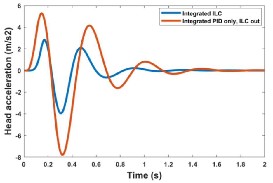
The HS-PID + Feedforward controller improves ride comfort under repeated bump excitation relative to all benchmark controllers. The HS-PID feedback loop attenuates the transient response, while the feedforward term reduces the repeatable component.
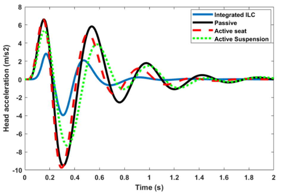
The active-seat-only controller slightly increases peak-to-peak head acceleration compared with the passive case. This is physically meaningful: when only the seat actuator is active, the vehicle body remains uncontrolled and the seat subsystem reacts to amplified chassis motion, locally increasing acceleration peaks through relative-motion dynamics and seat resonance. Coordinated control avoids this effect.
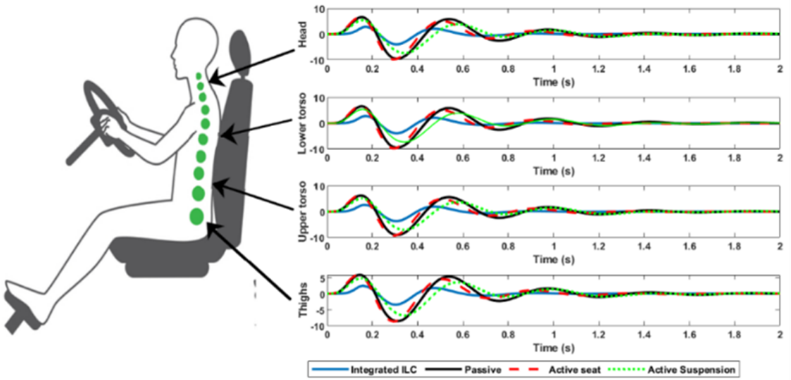
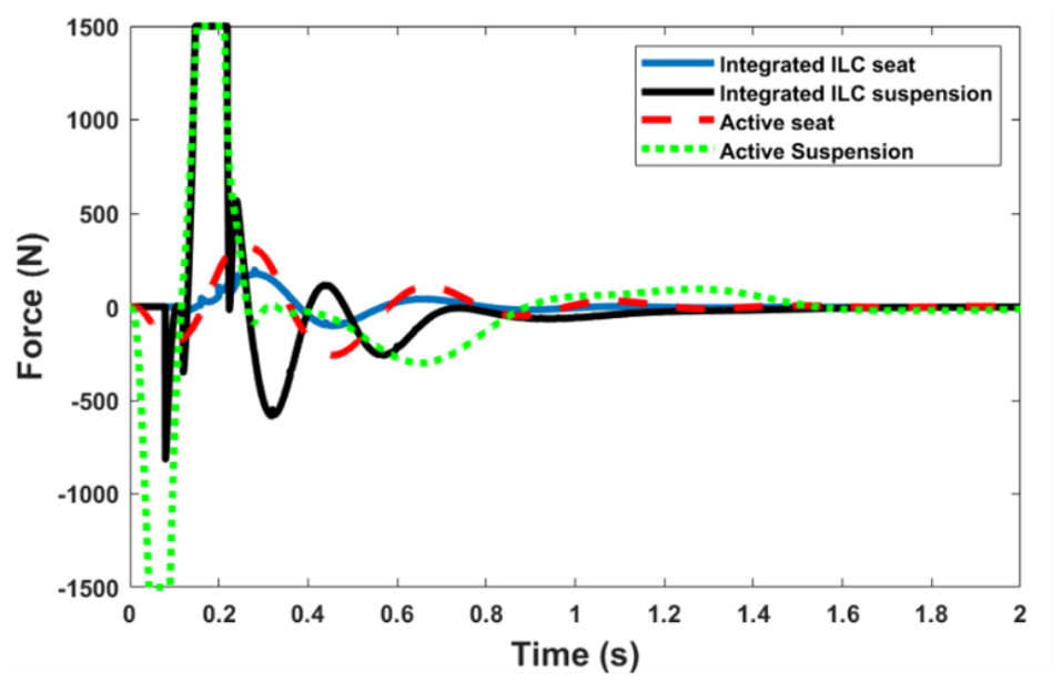
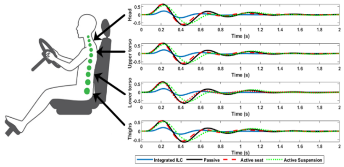
The driver-head acceleration responses are presented in Figure 2, the actuator forces in Figure 3, and the feedback–feedforward comparison in Figure 4. The segmental acceleration and displacement responses are shown in Figure 5 and Figure 6, respectively.
Compared with the passive case, the HS-PID + Feedforward controller reduces peak-to-peak head acceleration from 16.10 to 6.785 m / s 2 (≈57.9%) and RMS head acceleration from 3.007 to 1.058 m / s 2 (≈64.8%).

4.2. Vehicle Suspension Stroke and Seat Suspension Stroke Responses

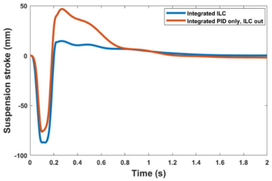
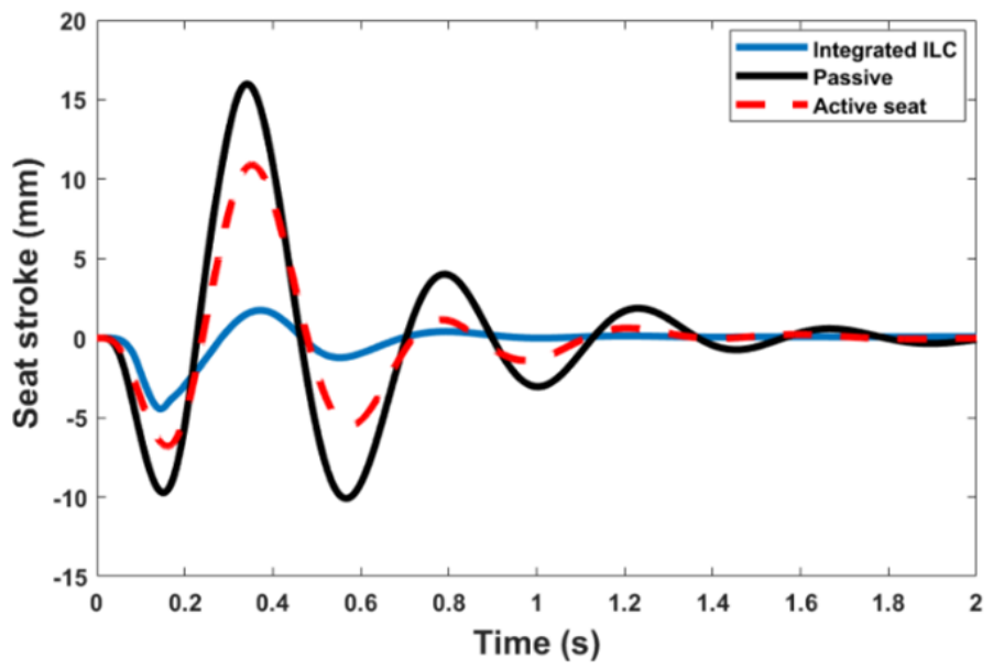
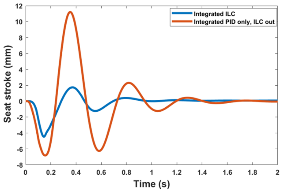
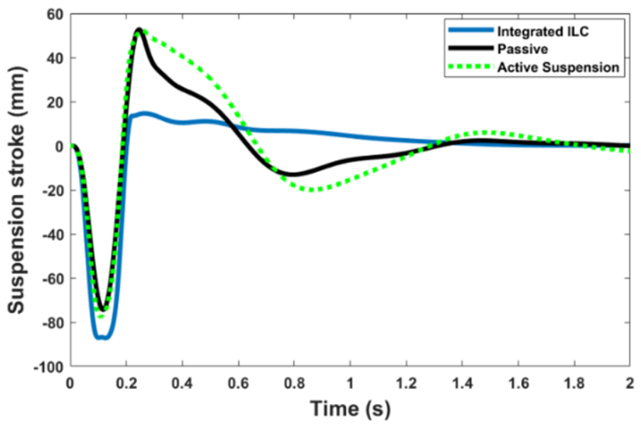
Figure 7, Figure 8, Figure 9 and Figure 10 distinguish the vehicle suspension stroke z s z u from the seat suspension stroke z f z s , with both quantities reported in meters. The captions, notation, and discussion are consistent with these physical definitions. Larger transient seat-suspension stroke during severe bump excitation is interpreted as an actuator-design consideration. The saturation limits in Equation (8) provide the framework for enforcing stroke and force constraints in practical implementation.

4.3. Ride-Quality Evaluation

All displacement and stroke quantities in Table 3, Table 4 and Table 5 are reported in meters, and all acceleration quantities are reported in m / s 2 . The proposed method is consistently labeled HS-PID + Feedforward.
The displacement reductions are larger than the acceleration reductions because the feedforward compensation primarily reduces low-frequency repeatable relative motion, whereas acceleration contains stronger high-frequency transient content from the bump impact. The present evaluation uses PTP and RMS measures appropriate for repeated bump/shock excitation. ISO 2631-1 [16] frequency-weighted acceleration and vibration dose value should be used in future work for broader road profiles.

5. Conclusions

This paper presented a coordinated HS-PID + Feedforward controller for an integrated IWM-EV seat–suspension–driver model. The feedforward term is motivated by the iterative learning control concept [10]; however, the reported numerical evidence does not constitute a demonstration of multi-iteration ILC convergence. The feedforward signal is treated as a fixed compensating term derived from the known repeatable bump response.
The HS-PID + Feedforward controller reduces occupant displacement and acceleration responses compared with passive, active-seat-only, active-suspension-only, and HS-PID-only baselines under repeated bump/shock excitation.
The conclusions are limited to the tested repeated bump scenario. More general claims require ISO 8608 random-road profiles [15], different vehicle speeds, parametric uncertainty studies, ISO 2631 frequency-weighted metrics [16], actuator-energy analysis, and hardware-in-the-loop validation. Advanced intelligent controllers, including type-3 fuzzy and neuro-fuzzy methods such as T3-ANFIS [14], may be integrated in future work for online uncertainty compensation and adaptive gain tuning.

Author Contributions

Conceptualization, M.A.E.; methodology, M.A.E.; software, M.A.E.; validation, M.A.E. and P.C.; formal analysis, M.A.E.; investigation, M.A.E.; writing—original draft preparation, M.A.E.; writing—review and editing, P.C.; supervision, P.C. All authors have read and agreed to the published version of the manuscript.

Funding

This research received no external funding.

Institutional Review Board Statement

Not applicable.

Informed Consent Statement

Not applicable.

Data Availability Statement

The original contributions presented in this study are included in the article. Further inquiries can be directed to the corresponding author.

Conflicts of Interest

The authors declare no conflicts of interest.

Abbreviations

The following abbreviations are used in this manuscript:
EVElectric vehicle
IWMIn-wheel motor
PIDProportional–integral–derivative
HSHarmony Search
ILCIterative learning control (used as feedforward-control motivation only)
HS-PID + FeedforwardProposed coordinated feedback–feedforward controller
RMSRoot mean square
PTPPeak-to-peak
VDVVibration Dose Value

References

  1. International Energy Agency. Transport–Energy System; IEA: Paris, France, 2023. [Google Scholar]
  2. Jacobson, M.Z.; Delucchi, M.A.; Bauer, Z.A.F.; Goodman, S.C.; Chapman, W.E.; Cameron, M.A.; Bozonnat, C.; Chobadi, L.; Clonts, H.A.; Enevoldsen, P.; et al. 100% Clean Energy Roadmaps for 139 Countries. Joule 2017, 1, 108–121. [Google Scholar]
  3. Li, W.; Long, R.; Chen, H.; Chen, F.; Zheng, X.; Yang, M. Policy Incentives for EV Uptake in China. Sustainability 2019, 11, 3323. [Google Scholar]
  4. International Energy Agency. Global EV Outlook 2025; IEA: Paris, France, 2025. [Google Scholar]
  5. Deepak, K.; Frikha, M.A.; Benômar, Y.; El Baghdadi, M.; Hegazy, O. In-Wheel Motor Drive Systems for EVs. Energies 2023, 16, 3121. [Google Scholar]
  6. Kim, Y.-J.; Sohn, Y.; Chang, S.; Choi, S.-B.; Oh, J.-S. Vibration Control for In-Wheel Motor Vehicles. Actuators 2024, 13, 80. [Google Scholar]
  7. Wang, Y.; Wang, C.; Zhao, S.; Guo, K. Deep RL Control for Active Suspension. Sensors 2023, 23, 7827. [Google Scholar] [CrossRef] [PubMed]
  8. Liu, M.; Zhang, Y.; Huang, J.; Zhang, C. Optimization Control for Dynamic Vibration Absorbers and Active Suspensions of In-Wheel-Motor-Driven Electric Vehicles. Proc. Inst. Mech. Eng. Part D J. Automob. Eng. 2020, 234, 2377–2392. [Google Scholar] [CrossRef]
  9. Samaroo, K.; Awan, A.W.; Islam, S. Semi-Active IWM Suspension. Machines 2025, 13, 47. [Google Scholar] [CrossRef]
  10. Arimoto, S.; Kawamura, S.; Miyazaki, F. Bettering Operation of Robots by Learning. J. Robot. Syst. 1984, 1, 123–140. [Google Scholar] [CrossRef]
  11. Heidarian, A.; Wang, X. Seat Suspension Technology Review. Appl. Sci. 2019, 9, 2834. [Google Scholar]
  12. Du, H.; Li, W.; Zhang, N. Integrated Seat and Suspension Control. IEEE Trans. Veh. Technol. 2012, 61, 3893–3908. [Google Scholar] [CrossRef]
  13. Jain, S.; Saboo, S.; Pruncu, C.I.; Unune, D.R. Quarter Car Semi-Active Seat Suspension. Appl. Sci. 2020, 10, 3185. [Google Scholar] [CrossRef]
  14. Mohammadzadeh, A.; Alattas, K.A.; Xie, W.-F.; Taghavifar, H.; Zhang, C.; Sakthivel, R. T3-ANFIS: Type-3 Adaptive Neuro-Fuzzy Inference System. IEEE Trans. Cybern. 2025, 55, 5387–5400. [Google Scholar] [CrossRef] [PubMed]
  15. ISO 8608:2016; Mechanical Vibration—Road Surface Profiles—Reporting of Measured Data. ISO: Geneva, Switzerland, 2016.
  16. ISO 2631-1; Evaluation of Human Exposure to Whole-Body Vibration. ISO: Geneva, Switzerland, 1997.
Figure 1. Integrated quarter-car, seat, and seated-driver model for the IWM-EV. The IWM is part of the wheel-side unsprung assembly.
Wevj 17 00379 g001
Figure 2. Bump responses of driver-head acceleration ( m / s 2 ). Controllers: Passive, Active seat, Active suspension, HS-PID, and HS-PID + Feedforward.
Wevj 17 00379 g002
Figure 3. Control forces u s and u f under bump excitation (N). HS-PID + Feedforward controller.
Wevj 17 00379 g003
Figure 4. Driver-head acceleration: HS-PID (feedforward disabled) versus HS-PID + Feedforward (feedforward enabled) ( m / s 2 ).
Wevj 17 00379 g004
Figure 5. Acceleration of human-body segments under bump excitation ( m / s 2 ): thighs m 1 , lower torso m 2 , upper torso m 3 , and head m 4 .
Wevj 17 00379 g005
Figure 6. Displacement of human-body segments under bump excitation (m): thighs m 1 , lower torso m 2 , upper torso m 3 , and head m 4 .
Wevj 17 00379 g006
Figure 7. Vehicle suspension stroke z s z u under bump excitation (m). Controllers: Passive, Active seat, Active suspension, HS-PID, and HS-PID + Feedforward.
Wevj 17 00379 g007
Figure 8. Vehicle suspension stroke z s z u : HS-PID (feedforward disabled) versus HS-PID + Feedforward (feedforward enabled) (m).
Wevj 17 00379 g008
Figure 9. Seat suspension stroke z f z s under bump excitation (m). Controllers: Passive, Active seat, Active suspension, HS-PID, and HS-PID + Feedforward.
Wevj 17 00379 g009
Figure 10. Seat suspension stroke z f z s : HS-PID (feedforward disabled) versus HS-PID + Feedforward (feedforward enabled) (m).
Wevj 17 00379 g010
Table 1. Mechanical parameters of the integrated IWM-seat-driver suspension model.
ParameterValueUnit
m u 20kg
m s 300kg
m f 15kg
m c 1kg
m 1 12.78kg
m 2 8.62kg
m 3 28.49kg
m 4 5.31kg
m d 10kg
c t 0N s/m
c s 2000N s/m
c s s 830N s/m
c c 200N s/m
c 1 2064N s/m
c 2 4585N s/m
c 3 4750N s/m
c 4 400N s/m
k t 180,000N/m
k s 10,000N/m
k s s 31,000N/m
k c 18,000N/m
k 1 90,000N/m
k 2 162,800N/m
k 3 183,000N/m
k 4 310,000N/m
Table 2. Simulation and controller parameters for reproducibility.
ItemValue/Description
Simulation softwareMATLAB/Simulink (R2021b or later)
Numerical solverode45 (Runge–Kutta 4/5), fixed step
Integration step Δ t = 1 × 10 4 s
Simulation duration T = 5 s
Initial conditionsAll states zero at t = 0
Bump profileHalf-sine, height 0.05 m, length 0.5 m, speed 20 km/h
Regulated output yDriver-head vertical acceleration ( m 4 )
Output matrix C s Selects head acceleration and suspension deflections
PID gains ( k p , k d , k i ) Tuned by Harmony Search minimizing RMS ( z ¨ 4 )
HS objective functionMinimize RMS ( z ¨ 4 ) subject to stroke and force limits
Actuator limits U lim , s = 3000 N, U lim , f = 1500 N
Allocation matrix KDiagonal; maps PID output to [ u s , u f ] T
Feedforward u 2 ( t ) Fixed signal derived from the repeatable bump response
Table 3. Peak-to-peak displacement under repeated bump excitation (m).
ControllerHeadImprove (%)Upper TorsoImprove (%)Lower TorsoImprove (%)ThighsImprove (%)
Passive1.30501.30001.26001.2080
Active seat1.24204.81.23704.81.19605.11.14305.4
Active suspension1.128013.61.125013.51.095013.11.059012.3
HS-PID1.049019.61.046019.51.016019.40.975619.2
HS-PID + Feedforward0.415568.20.413168.20.394068.70.369869.4
Table 4. Peak-to-peak acceleration under repeated bump excitation ( m / s 2 ).
ControllerHeadImprove (%)Upper TorsoImprove (%)Lower TorsoImprove (%)ThighsImprove (%)
Passive16.1016.0215.3114.42
Active seat16.40−1.916.30−1.715.50−1.214.50−0.6
Active suspension12.7420.912.6820.812.2220.211.6219.4
HS-PID13.0518.912.9819.012.4218.911.7418.6
HS-PID + Feedforward6.78557.96.70058.26.30158.85.89259.1
Table 5. RMS displacement under repeated bump excitation (m).
ControllerHeadImprove (%)Upper TorsoImprove (%)Lower TorsoImprove (%)ThighsImprove (%)
Passive0.22980.22920.22300.2148
Active seat0.20958.80.20898.90.20309.00.19539.1
Active suspension0.20948.90.20898.90.20478.20.19907.4
HS-PID0.185619.20.185119.20.180519.10.174318.9
HS-PID + Feedforward0.065571.50.065371.50.062871.80.059672.3
Disclaimer/Publisher’s Note: The statements, opinions and data contained in all publications are solely those of the individual author(s) and contributor(s) and not of MDPI and/or the editor(s). MDPI and/or the editor(s) disclaim responsibility for any injury to people or property resulting from any ideas, methods, instructions or products referred to in the content.