Article

Volvo SmartCell: A New Multilevel Battery Propulsion and Power Supply System †

by
Jonas Forssell
*,
Markus Ekström
,
Aditya Pratap Singh
*,
Torbjörn Larsson
and
Jonas Björkholtz
Volvo Car Corporation, 418 78 Gothenburg, Sweden
*
Authors to whom correspondence should be addressed.
This article is a revised and expanded version of a paper entitled “Volvo SmartCell: A New Multilevel Battery Propulsion and Power Supply System”, which was presented at EVS38, Gothenburg, Sweden, 15–18 June 2025.
World Electr. Veh. J. 2026, 17(4), 190; https://doi.org/10.3390/wevj17040190
Submission received: 25 February 2026 / Revised: 26 March 2026 / Accepted: 31 March 2026 / Published: 3 April 2026

Abstract

This research paper presents Volvo SmartCell, an AC battery technology that integrates modular multilevel converters and battery cells to form a unified system for electric vehicle propulsion and power supply. The research work addresses the broader challenge of reducing driveline cost and complexity by replacing traditional components such as inverters, onboard chargers, centralized DC/DC converters, vehicle control units and many more. SmartCell uses distributed Cluster Boards comprised of H-bridges which are controlled via wireless communication to generate AC voltage, deliver redundant low voltage power, and support cell level protection mechanisms. The prototype testing demonstrates that the system can supply traction power by engaging clusters according to the required voltage depending on motor speed, achieve AC grid charging by synthesizing sinusoidal voltages without a dedicated charger, and provide autonomous DC/DC operation through cluster level voltage regulation. Simulations further indicate that multilevel voltage generation can reduce switching losses and improve electric machine efficiency compared to conventional systems. Additional benefits include active cell balancing, support for mixed cell chemistries, and high redundancy through multiple independent power branches. Challenges remain in wireless bandwidth limitations and cost optimization of Cluster Boards. Ongoing development aims to enhance communication robustness and validate safety for non-isolated grid charging.

1. Introduction

Electric vehicles have demonstrated their viability as an attractive alternative to internal-combustion powertrains, driven by improved driving performance, reduced environmental impact, and increasing advancements in battery and power-electronic technologies and supply chain. Despite these benefits, widespread adoption still depends on lowering system cost, reducing architectural complexity and increasing reliability to ensure customers attain the true benefits of electrification. As the automotive industry transitions into the next generation of electrification, where cost and system integration are vital, there is a growing opportunity to rethink how propulsion, charging, and auxiliary power are integrated. Emerging trends include embedding inverters within electric machines, relocating charging and battery-monitoring electronics into the battery pack, and expanding auxiliary supply architectures through 48-V domains, all while exploring multilevel conversion techniques which are capable of delivering higher efficiency, reducing cost and complexity, scalable technology, high redundancy and robustness while saving weight and space [1,2]. Collectively, these developments indicate a clear technical trajectory: consolidating traditionally separate functions into unified, battery-integrated power-electronic systems. This research paper elucidates the design, functionality, and benefits of such an approach through Volvo SmartCell, a multilevel, cell-integrated propulsion and power-supply system combining modular multilevel converter concepts with distributed battery clusters to achieve a new class of AC battery architecture.
In parallel, the broader field of battery-integrated power electronics has gained significant momentum, with research on modular multilevel batteries (M2Bs), cascaded H-bridge (CHB) inverters, and battery-integrated modular multilevel converters (BI-MMCs) demonstrating that embedding power-electronic capability at the cell or module level can substantially improve system flexibility, efficiency, and redundancy. These architectures replace the traditional system where the battery is treated as a passive DC source supporting downstream converters, with highly modular, actively controlled distributed cluster systems which are capable of synthesizing multilevel AC waveforms directly from cell clusters. Prior investigations have shown that such multilevel topologies can reduce semiconductor switching losses, improve electric-machine efficiency through smoother waveforms, and enable advanced features including direct AC charging, intrinsic fault tolerance, mixed-chemistry operation, and active state-of-charge balancing. However, the same studies also highlight critical challenges, such as high component count, complex capacitor-voltage balancing, circulating-current suppression, and the need for tightly synchronized, low-latency communication across many distributed clusters [3].
Volvo SmartCell builds directly upon this evolving research landscape and extends it toward automotive industrialization. By combining a cascaded H-bridge architecture, per-cluster intelligence, wireless synchronized control, and integrated DC/DC supply within a single battery-embedded platform, SmartCell consolidates the traction inverter, onboard charger, centralized DC/DC converter, BMS, and power-distribution unit into one unified AC battery system. This approach not only reduces the number of high-voltage components but also leverages the natural advantages of multilevel voltage synthesis to improve efficiency, simplify thermal management, and create a highly redundant power architecture. Through system-level validation in propulsion, grid-connected AC charging, and auxiliary power generation, SmartCell demonstrates how battery-integrated multilevel conversion can transition from academic research to practical, scalable engineering applicable to next-generation electric vehicles [4].

2. SmartCell Concept Description

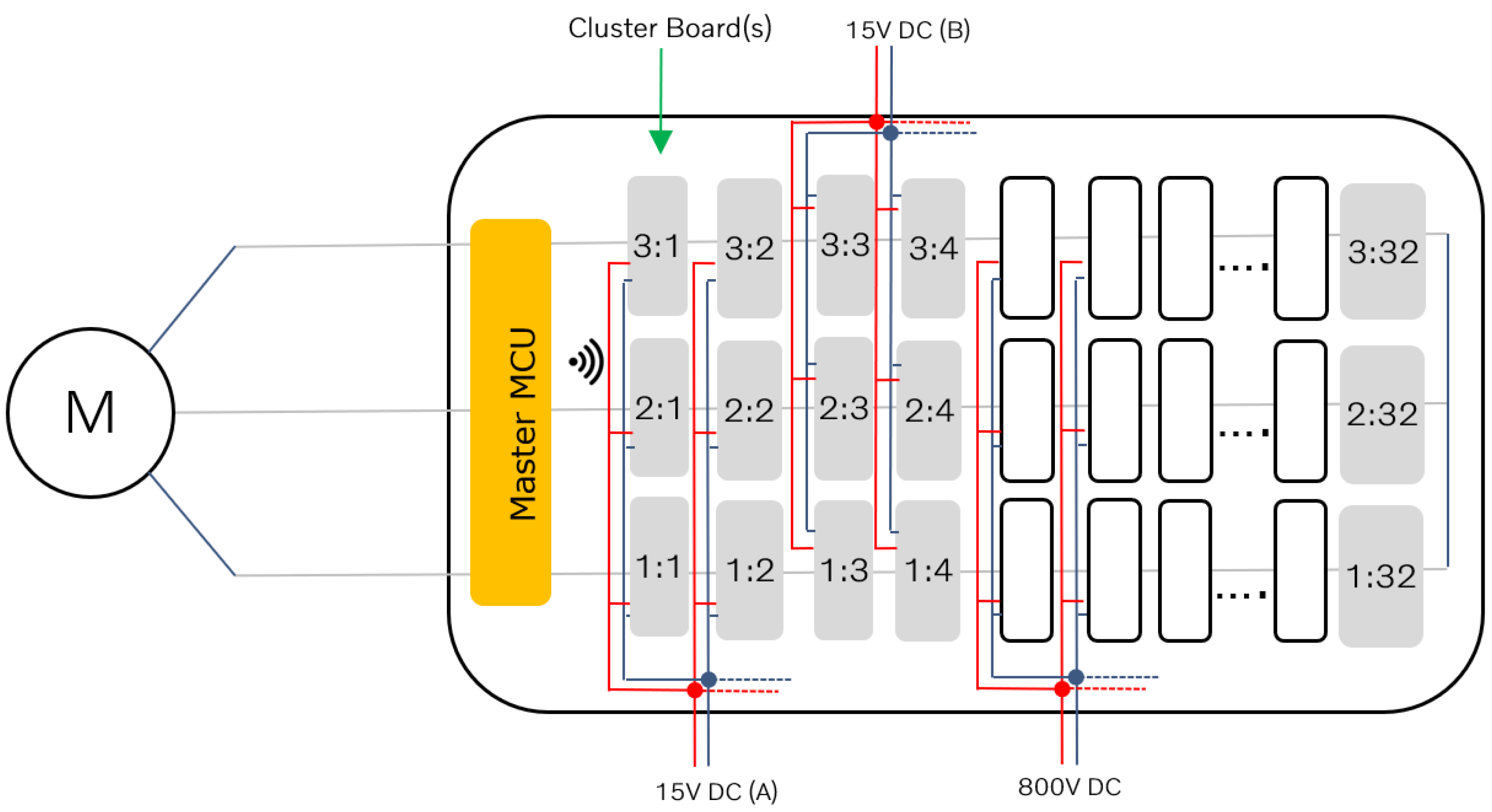
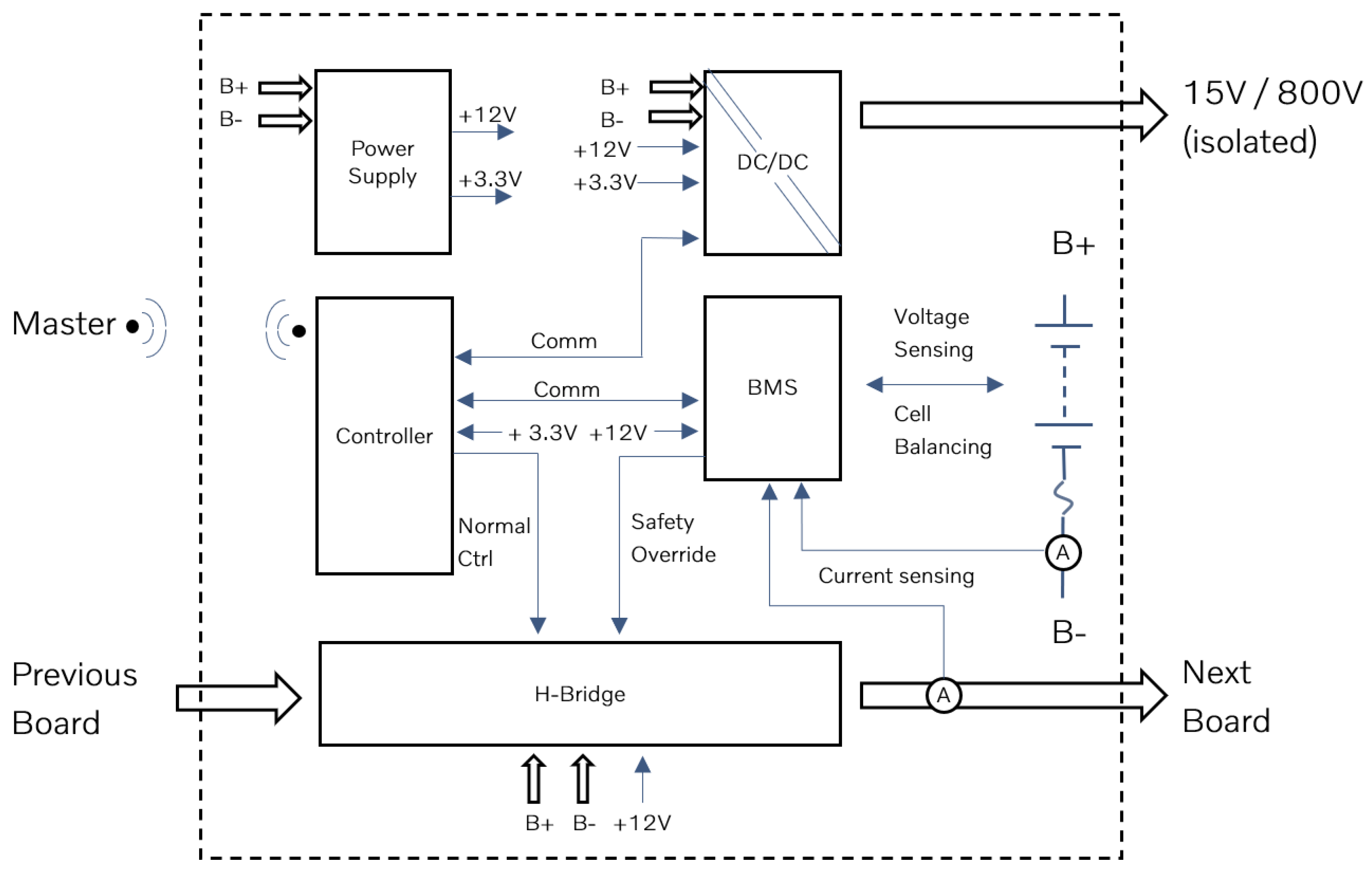
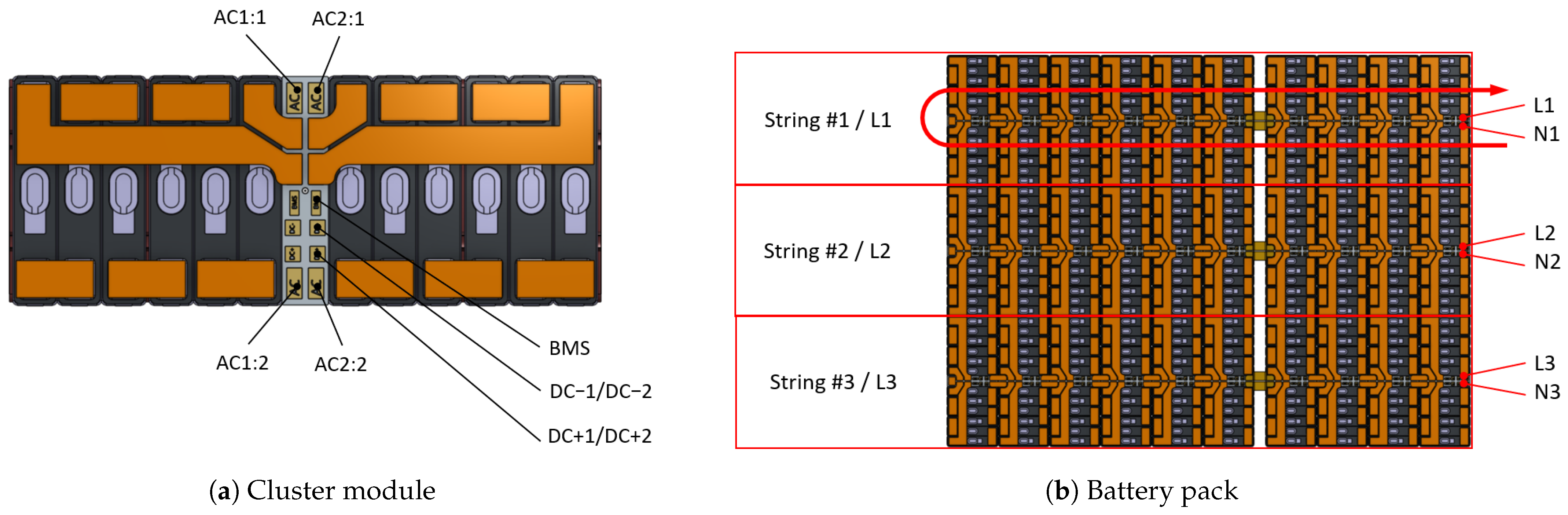
SmartCell is a cascaded H-bridge (CHB) battery system [5]. The main component is the Cluster Board which controls a group of battery cells referred to as a cluster and primarily includes the H-bridge and the DC/DC converter, as shown in Figure 1 and Figure 2. The Cluster Boards are in constant communication with a Master Board where the primary controller resides.

2.1. System Overview

SmartCell system comprises three independent parallel strings in which several Cluster Boards are connected in series as illustrated in Figure 1 and explained in Section 2.2. The cells through the Cluster Boards are connected to the electric machine to provide propulsion power. The Cluster Boards are connected in series in three independent phases X with each cluster having a unique identifier X:Y highlighted in Figure 1 (1:1, 2:2 and 3:3…). The output from the strings is routed via a Master Board where the total voltage and current for each string can be monitored. Radio transceivers are used for communication between Cluster Boards and Master Board.
The entire communication is based on radio up-link as it is cost-effective and robust. Also, because of the varying potential of the clusters, this communication is isolated. We have configured the up-link on existing wireless Battery Monitoring System (BMS) technology complemented with a customized protocol to achieve the required bandwidth and clock synchronization between the clusters. Each cluster also has a second output from the DC/DC converter on the Cluster Board. This is an isolated output of the peak power ≈ 400 W and is available in two options: The first is a 15 V output, which is used to power the vehicle auxiliaries such as onboard computer, lamps, steering power assist, etc. This output is available in two independent branches that comply with high Automotive Safety Integrity Level (ASIL) [6]. The second output option is an 800 V DC supply for power climate loads such as an AC compressor and heater. Since these loads are not classified for safety, there is no requirement for two independent branches for it. These loads are also predictable, which is not the case with 15 V loads. The DC/DC’s in each branch are connected in parallel and are controlled to balance the load between them.

2.2. Cluster Board

The Cluster Board is the heart of the system, and it is very critical that this component is cost-effective and highly efficient to provide the utmost advantages of the SmartCell system. In SmartCell a few cells are grouped together in series to form a cluster which is controlled by their respective Cluster Board. The formation of cluster allows to use high-current switches that are rated for low voltage in the H-bridge, and puts the stepping stone for more advanced, efficient and cost-effective electric driveline solution than traditional available systems. Figure 2 illustrates the electrical components and flow of communication between them inside the Cluster Board. The DC/DC converter is isolated and has its own controller for ASIL functionality. The controller monitors the DC/DC converter’s output voltage and turn-on the converter if its voltage drops below the requested voltage. The requested voltage can be set by the local controller block which helps to prevent turning on all the DC/DC’s at the same time if the load on the system is low. The BMS monitors the cluster’s voltage, current, and temperature and keeps constant communication with the Master Board through the wireless up-link in a so-called black channel. The BMS also has a strong safety override to the gate driver. This override can force the H-bridge into bypass mode and thereby disconnect the cluster from the main system during any hazard.
The controller is a traditional Main Controller Unit (MCU) with integrated wireless radio up-link. The controller runs the control firmware for the H-bridge which allows the clusters to generate an AC voltage via PWM switching. The H-bridge will control the connection of the cluster to the main system. The full H-bridge allows the cluster to connect the cells with positive or negative polarity and also to keep them in bypass mode.

2.3. Master Board

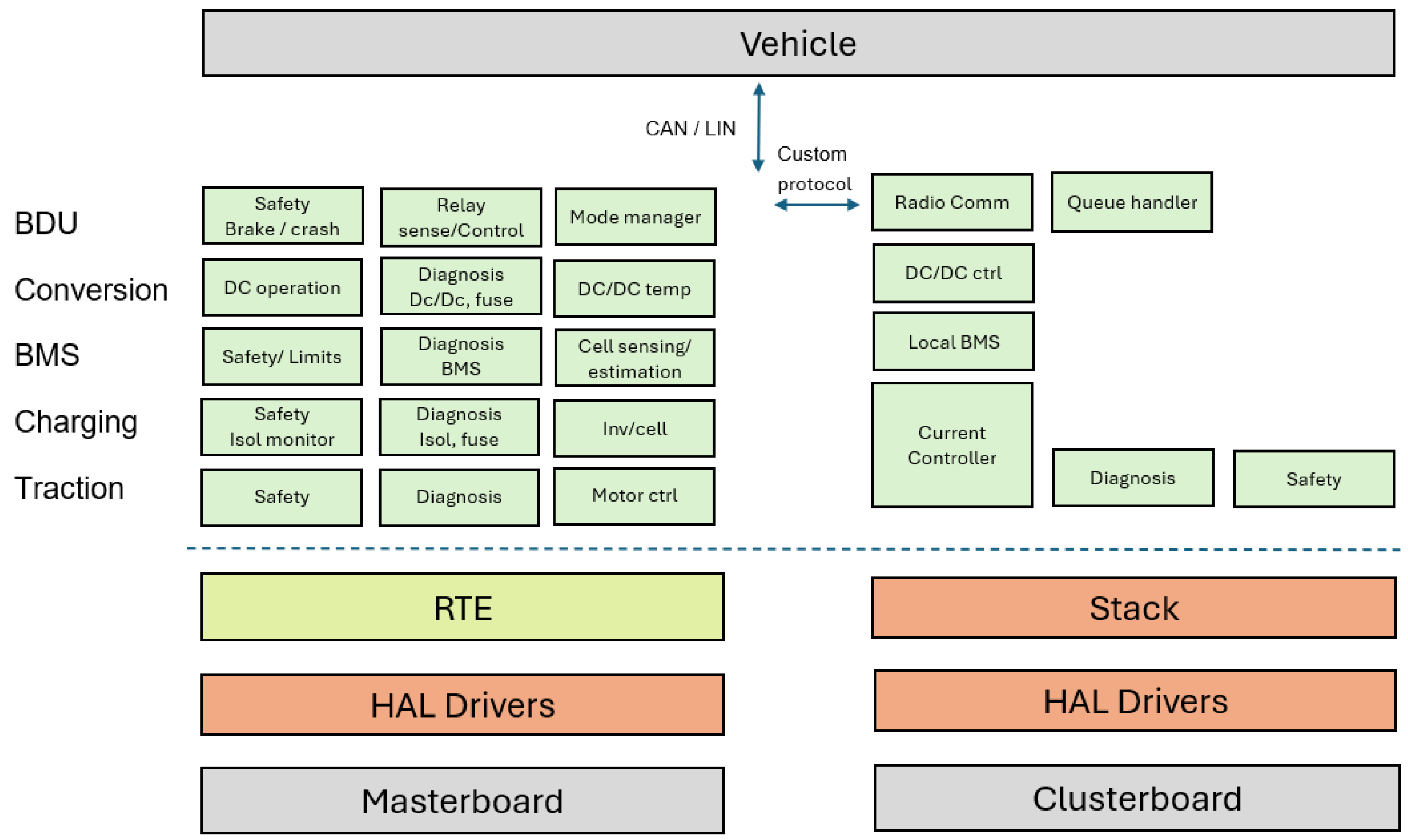
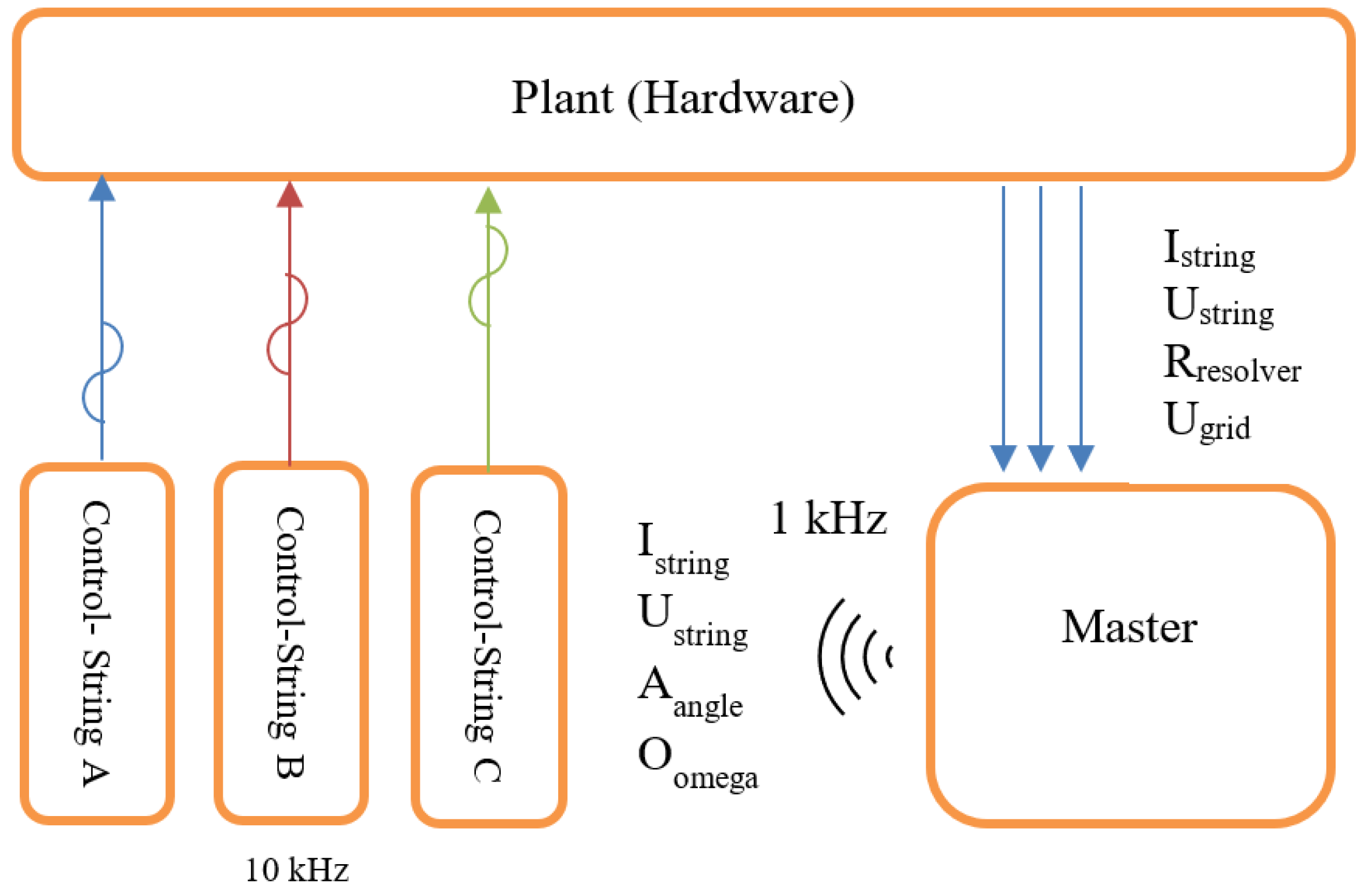
The Master Board in the SmartCell architecture functions as the central coordinator and safety-critical control unit of the entire system. As shown in the system Figure 3, the Master Board hosts the high-integrity software stack and manages all top-level propulsion, charging, and safety functions across the pack. It receives inputs such as phase currents, phase voltages, isolation measurements, relay states, temperature sensing, residual current detection, and CAN/LIN communication, and it processes these signals to generate synchronized switching commands for every Cluster Board. Master Board broadcasts resolver angle, resolver velocity, voltage requests, and torque-related control signals to all clusters, which enables precise AC voltage synthesis and coordinated multilevel control across the distributed H-bridges. The Master Board is also responsible for safety supervision, including monitoring HV isolation, enforcing ASIL-compliant dual-branch LV supplies, validating BMS data from each cluster, and commanding bypass or shutdown modes if a cluster exhibits over-temperature, over-current, or voltage anomalies. In essence, the Master Board operates as the brain of SmartCell which handles real-time computation, system safety, communication, and multi-phase power coordination, while the Cluster Boards serve as distributed actuators executing its commands. The Master Board integrates the function of BDU, hence eliminating the separate need of it.

3. SmartCell System for an Electric Vehicle

This chapter describes the primary advantages of the SmartCell system and its ability to significantly reduce the number of various components, enabling tighter integration of the remaining parts into a Master Board and several Cluster Boards. This integration allows for the incorporation of almost the entire propulsion system within the battery pack itself, resulting in a completely flat pack.

3.1. System Design

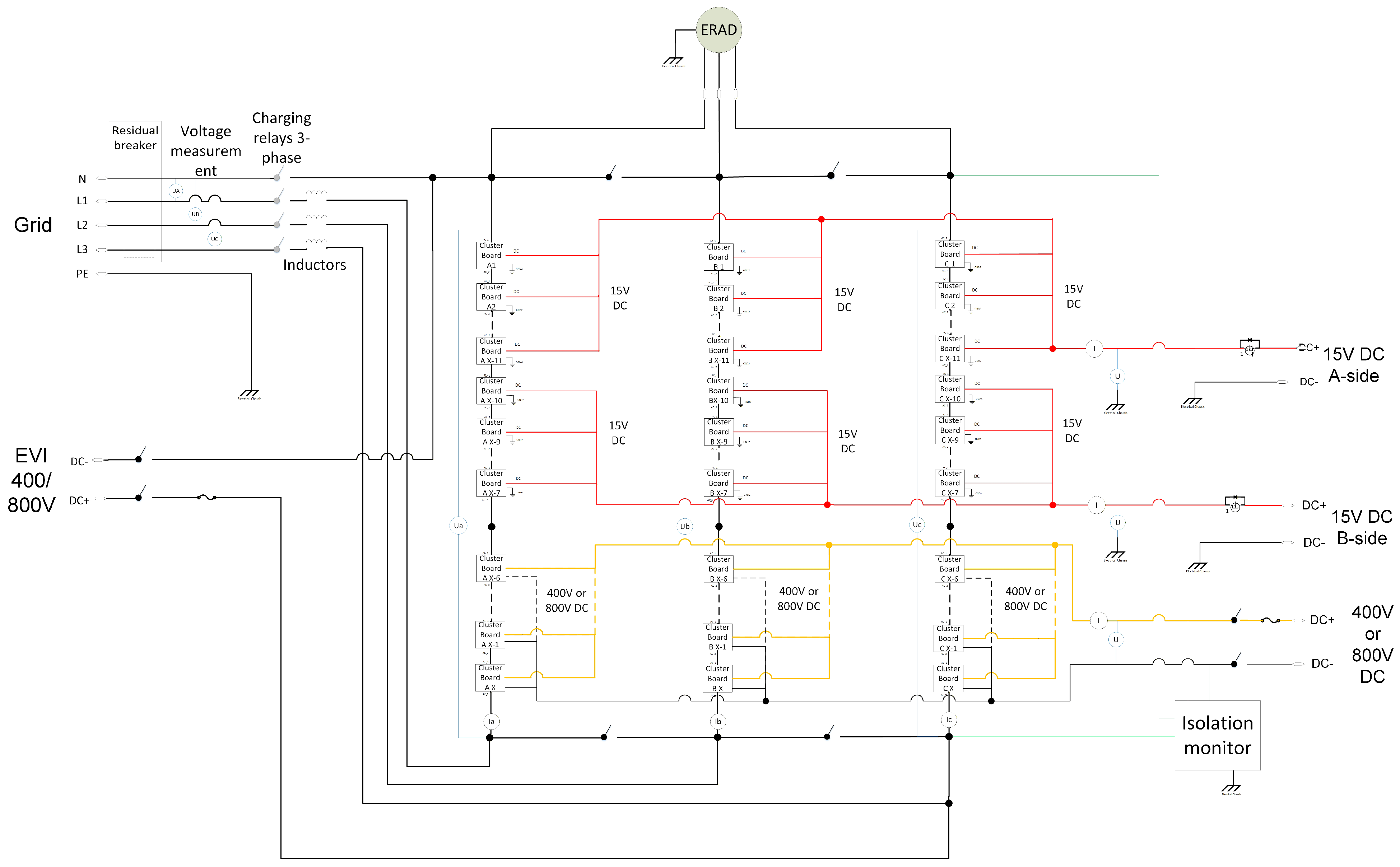
The core of the system comprises the Cluster Boards, which are connected to various ports as depicted in Figure 4. The AC charging input is located on the left, where each phase is connected to a separate string, and the neutral is connected to the common top side. Several auxiliary relays enable the synchronization of clusters with the grid prior to initiating charging. The system is capable of handling one-, two-, or three-phase AC charging using the same hardware. On the left, the DC-charging mode is illustrated, where the three strings operate in parallel and are configured to match the DC-charging voltage. If the battery pack is designed for 800 V per string and the vehicle is to be charged from a 400 V charger, the clusters can be adjusted to reduce the string voltage to match the charger voltage. The DC/DC converters output two independent low voltage supplies, indicated in red, while a high voltage supply which can be in range of 60 V to 1000 V in electric vehicle is shown in yellow. This high voltage supply is connected to the climate system and other non-safety-critical loads. Finally, isolation checks are performed at critical points, as indicated in green.

3.2. System Safety

It is imperative that the system complies to highest level of safety standards. Hence, system safety principles have been integrated from the start of the SmartCell concept. The highest requirements specify that cells operate within specified limits and maintain a stable and secure power supply to the vehicle, which is particularly crucial with the introduction of autonomous driving. The main processor is compliant with system safety standards and supports wireless communication. This wireless communication is secured through two redundant channels, ensuring fail-safe communication in the event of a failure in one channel. Additionally, the main phase current measurements are backed up by secondary current measurements on each Cluster Board. The clusters are programmable and can be shutdown via controls. However, as a backup, large current relays can be activated to disengage the clusters. Also, in order to enhance the system safety for non-isolated AC charging, continuous isolation monitoring, default by-pass, relays with fast release and bouncing time, ASIL D on main processor on the Master Board, redundant measurements for both Current and Voltage and shutdown capability through hardware-level safety have been added to prevent hazardous current paths during both traction and charging operations. The DCDC transformers are galvanically isolated to feed climate HV DC loads which are the second largest consumer of both energy and power after traction.
The SmartCell architecture incorporates a multilayered safety concept in which each cluster and each individual cell is continuously monitored and protected through both hardware-level and MCU-level mechanisms. The Cluster Board contains an integrated BMS and gate-driver safety override which are capable of pushing the H-bridge into bypass mode, thereby electrically isolating the cluster and through that all the cells on the cluster whenever over-voltage, under-voltage, over-current, or over-temperature conditions are detected. In the case of an event outside the defined operating window, the Cluster Board immediately blocks all the cells from participating in any activity, which avoids exposing the cell to high current stresses that could lead to short circuit, lithium plating, thermal runaway, or irreversible degradation. Instead of permitting further HV operation, the system transitions the affected cluster into a controlled recovery mode. SmartCell Cluster Board design ensures that cells inside cluster are operated in same way and active balancing is ensured at cluster level to maintain SOH, SOC and SOT [7].

3.2.1. Self-Protection

The H-bridge on each Cluster Board controls the connection of each cluster to the entire system. In the default mode, the H-bridge is disconnected to ensure no external voltage from the cluster. Many hazards can be addressed via the by-pass mode, for example, if any of the cells inside a cluster reaches a critical lower voltage during use, the cluster can take the decision to protect itself. This mechanism is hardwired to protect the cluster from over-voltage, under-voltage, over-current and over-temperature.

3.2.2. Separated Power Supplies

The power supply to the vehicle is achieved by two independent branches which complies with ISO 26262 and can support safety-relevant vehicle functions necessary for automated driving levels 3–5 [6]. The output of the DC/DC converter of each cluster is connected in parallel to the others. Since each branch consists of multiple DC/DC converters and each with its own independent power source, the redundancy becomes very high. Each DC/DC has its own controller with constant monitoring of the voltage in the system, which allows the DC/DC to continue running even if the communication to the master is interrupted or there is a hardware or software failure in the controller of the Cluster Board.

3.3. Reduction of AC Electromagnetic Interference (EMI)

The flow of current through a conductor induces a significant magnetic field around it. To mitigate the high AC magnetic fields generated by the SmartCell and comply with the relevant directives [8,9], the busbar layout is engineered to include a counteracting current path in close proximity. This design effectively cancels out the magnetic field around the conductor, as depicted in Figure 5. The same principle is used throughout the design to minimize EMI. In a normal DC battery this is not an issue, but since the SmartCell generates AC current in the battery itself, there are strict requirements on the allowed field and the SmartCell design fulfills these requirements.

3.4. Higher Degree of Freedom

SmartCell allows for individual control of the clusters in the system. This opens up for more degrees of freedom compared to a traditional system. The duty cycle of a cluster can be controlled in such a way that all the clusters are actively balanced, for example, if a cluster has a lower state-of-charge compared to the other clusters, then it can be actively balanced through charging via other clusters or by utilizing less during driving until its capacity is balanced. This active balancing can be made during driving, charging, or even in standby conditions. This active balancing can be taken one step further when combined with different cell characteristics. SmartCell empowers to use mixed cell size and chemistry according to the requirements. For example, the SmartCell system can utilize a cell having a chemistry with high energy but high internal resistance (low power capacity) during low power requirements and can use high-power cells with low resistance (low energy capacity) during the need of high instant power. Another possibility is to combine cells of different sizes in the same pack and enhance space utilization.

3.5. Cost Analysis

SmartCell introduces a larger number of low-voltage MOSFETs and distributed Cluster Boards, but still overall system economics remain favorable because the architecture replaces nearly the entire high-voltage power-electronics stack traditionally required in an electric vehicle. SmartCell is an 8-in-1 integrated platform, combining the traction inverter, front/rear inverters, DC/DC converter, onboard charger, BMS, BDU, vehicle control, and auxiliary power supply into a single system embedded inside the battery pack. This consolidation eliminates multiple high-cost and high-complexity subsystems which substantially reduces wiring, enclosures, control units, cooling hardware, and EMI filtering stages that conventional systems have to support. A distributed CHB-based architecture like SmartCell also leverages low-voltage MOSFETs, which are significantly cheaper than high-voltage SiC devices. Also, independent research by ref. [10] demonstrates that full-bridge BI-MMC topologies can exceed SiC two-level inverter efficiency, while benefiting from the drastically lower cost of commodity MOSFETs and economies of scale derived from repeating identical submodules. Thus, although the number of switches increases, the cost per functional unit decreases, and the system eliminates the inverter and OBC components that are among the highest-value and highest-cost items in the propulsion stack.
The SmartCell research paper explicitly acknowledges costs related to Cluster Boards but highlights that system-level simplification reduces the number of variants, interfaces, and assembly steps, with manufacturing becoming more modular and scalable. Also, another independent research by ref. [11] shows that Reconfigurable Cascaded Multilevel Converters (RCMCs) can perform direct AC charging without any dedicated charger, reducing hardware stages and enabling optimized charging algorithms that lower losses by up to 93% depending on switching patterns with lesser components than traditional system. Overall, external research and SmartCell’s system-level validation consistently demonstrate that the savings associated with eliminating the inverter, OBC, and centralized DC/DC converter outweigh the added costs of distributed MOSFET-based cluster electronics, establishing SmartCell as a cost- and efficiency-optimized next-generation EV powertrain architecture.

4. Communication and Control

One of the primary challenges with the SmartCell system was identifying a cost-effective, non-galvanic communication interface between the Master Board and the Cluster Boards. Various communication technologies were evaluated to determine the best fit for the interface requirements, which are complex due to the need to synchronize the Cluster Boards within a microsecond and continuously transfer critical data. Among the technologies considered, wireless communication was selected for its ability to meet the criteria of cost-effectiveness, non-galvanic properties, and high-speed communication. Additionally, wireless BMS have become widely available from several suppliers, aligning with SmartCell interface requirements. This section explains the wireless communication interface and control mechanisms between the Cluster Boards and the Master Board [12,13,14].

4.1. Wireless Communication Protocol

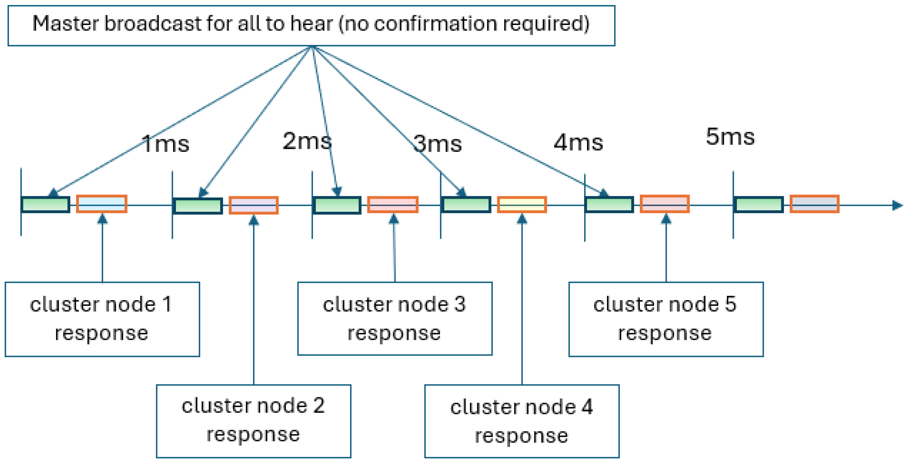
A dual broadcast interface protocol is developed through which the Master Board transmits at a fixed interval to all the Cluster Boards, as illustrated in Figure 6. The communication is strictly downstream and no confirmation is sent by the Cluster Boards about receiving the information from the Master Board. The Master Board broadcasts resolver angle, resolver velocity, and other critical parameters at 1 kHz to the Cluster Boards to generate the required voltage profile. The Cluster Board also sends data like state-of-charge to Master Board at 1 kHz, but one Cluster Board at a time. The consequence of this is that the upstream communication is significantly slower than the downstream and, directly related to the number of clusters in the system [15].
The Cluster Boards can extrapolate the next means of action based on earlier received data up to five consecutive transmissions during transmission failure. The Cluster Boards go into self-protection if they do not receive information from the Master Board even after five successive extrapolations and come to the active mode once the communication is restored.
The SmartCell communication protocol is designed to support up to 100 distributed clusters while guaranteeing deterministic, cyber-secure, and highly synchronized operation across the entire distributed system. In order to maintain coherent AC waveform generation, all nodes at the Master Board and every Cluster Board operate with synchronized clocks achieving <0.1 µs timing skew, which ensure that cluster-level H-bridge switching events remain phase-aligned. Each communication frame consists of a compact 50-byte payload (excluding protocol overhead), allowing high-frequency updates without saturating the wireless channel. To ensure high reliability, the system has a packet-delivery success rate requirement to be greater than 95%, and, critically, no cluster should miss more than five consecutive messages, preventing synchronization errors or unsafe behavior during traction or charging. In order to ensure real-time performance, end-to-end broadcast latency must remain below 1 ms, even in the presence of up to 100 receiving nodes. The cyber-security protections such as message authentication, integrity checking, and replay-attack prevention are mandatory to ensure that only valid and trusted control frames are executed by the clusters.

4.2. Power Control

In SmartCell a unified control principle for both AC charging and traction control has been developed, termed Power Control. The Master Board senses current, voltage, and resolver data, which serve as inputs to a Park–Clarke transformation to derive the direct and quadrature axis currents (Id and Iq). A proportional–integral (PI) regulator acts on these values to generate a voltage request for each string (Ustring), as depicted in Figure 7. This request is expressed in vector format to ensure consistency and predictability in wireless control values. The resolver angle, along with resolver velocity ( ω ), enables the clusters to predict future angles in the event of a communication message loss.
Each Cluster Board utilizes data from the Master Board to determine the precise timing for the generation of a sinusoidal voltage with the correct amplitude and frequency. This timing decision is based on an internal clock within each Cluster Board, synchronized with a common time reference. Additionally, each Cluster Board is equipped with internal current sensing for the string, which facilitates the operation of an internal closed-loop correction algorithm at a high frequency. The Power Control algorithm addresses deviations from the request from the Master Board and transient disturbances. As the same algorithm operates on each cluster and the sensed current is consistent throughout the string, all Cluster Boards reach the same conclusion simultaneously to ensure that corrective actions affect the entire string uniformly.

4.3. DC/DC Control

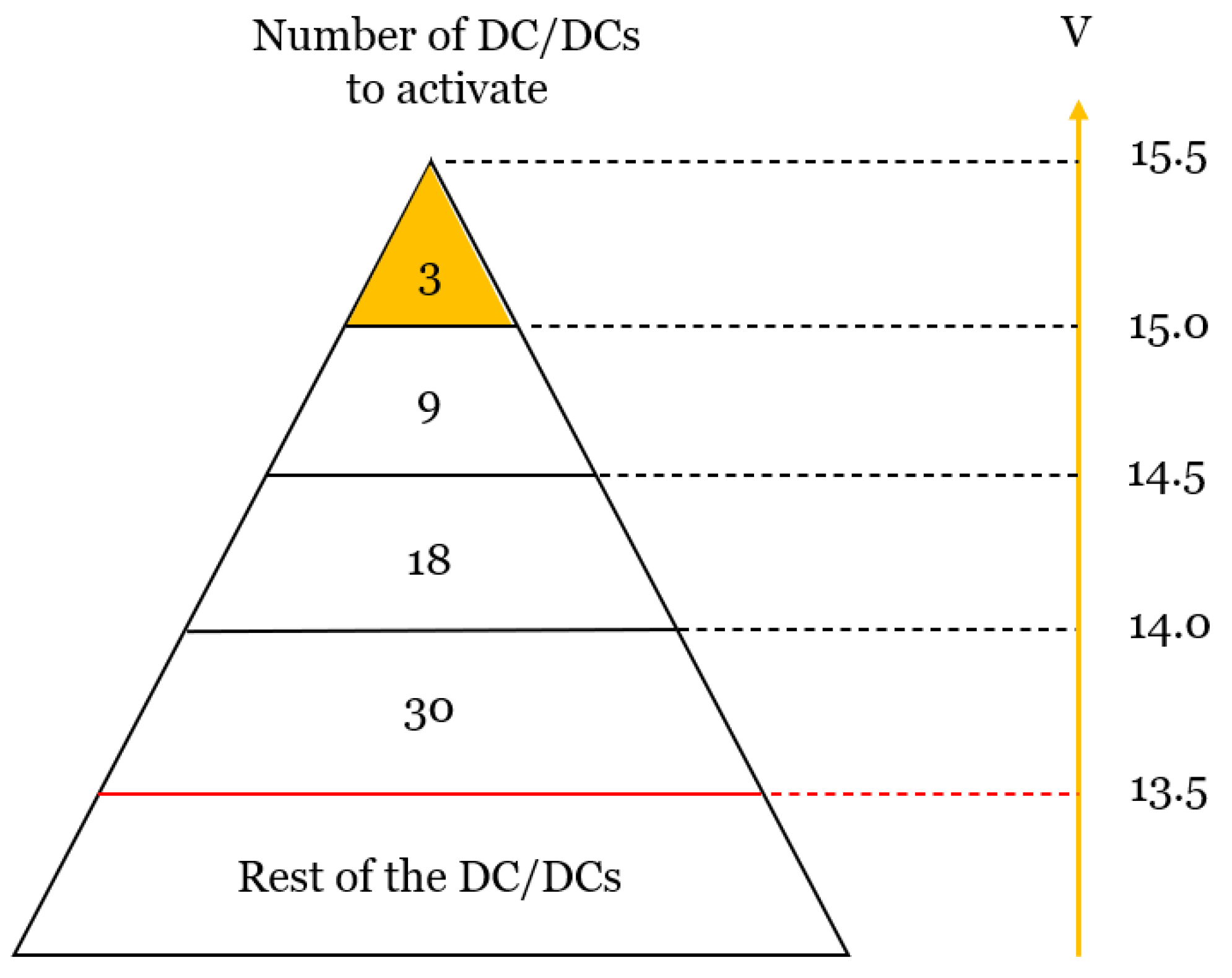
In order to fulfill system safety requirements, the DC/DC converter boarded on each Cluster Board operates on their own and has no communication between them. Each DC/DC converter has a target voltage and operates accordingly. The DC/DC converter maintains the requested voltage by increasing or decreasing its power output. Figure 8 illustrates the control logic to engage the right number of DC/DC converters by programming different target voltages to meet the vehicle load requirements. On the other end of the spectrum, when a vehicle is parked and in a low state of power consumption, only one or a few DC/DC converters are turned on to provide the needed power. The configuration on how to distribute the DC/DC target voltages is subjected to optimization because it is a trade-off between efficiency and transient response.

5. Results

SmartCell is a multilevel cell-based battery propulsion and power supply system. It leverages the full capabilities of various functionalities and components, such as H-bridges, wireless communication, and small, independent DC/DC converters, to meet all system requirements with high efficiency and enhanced control. The fundamental distinction between SmartCell and conventional systems lies in the operation and control of battery-pack voltage. SmartCell builds voltage by stacking the voltage of individual clusters according to the power (voltage) requirement, whereas traditional inverter-based systems operate on the full DC voltage to achieve the target voltage. The results of this innovative method of combining MMC and cells to simplify controls and eliminate the need for various components like an inverter, an on-board charger, and to enhance overall system efficiency are presented in this chapter.

5.1. Traction

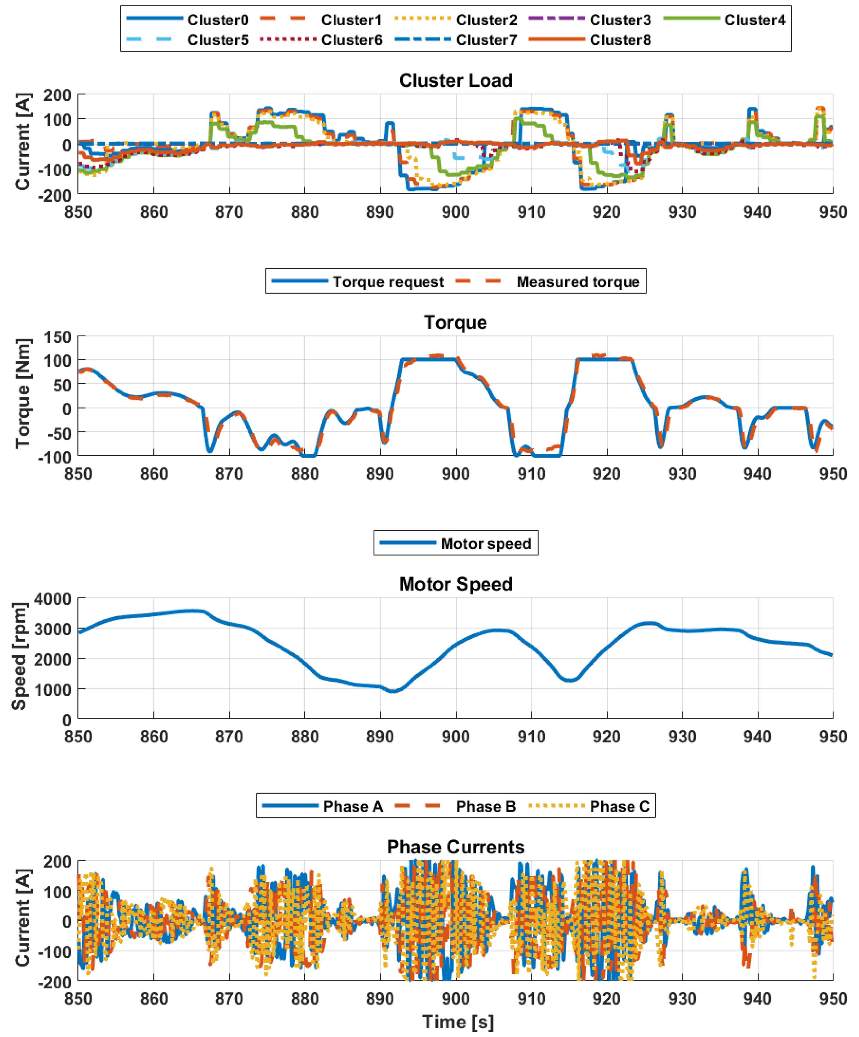
Figure 9 shows the test results for the utilization of clusters during a segment of the worldwide Harmonized Light Vehicle Test Cycles (WLTCs) drive cycle. The top graph shows the engagement of the clusters to supply current for the required torque, as highlighted in the second graph. The number of active clusters depends upon the requested voltage, which varies with electric machine speed as shown in third plot. The negative amplitude of the current illustrates the discharge of the clusters to achieve the requested propulsion torque whereas the positive amplitude of the current is depicted during regeneration, as shown in the first graph. The last graph represents the total phase current delivered to the electric machine, where the current frequency depends on the fundamental frequency of the electric machine.

5.2. Grid Charging

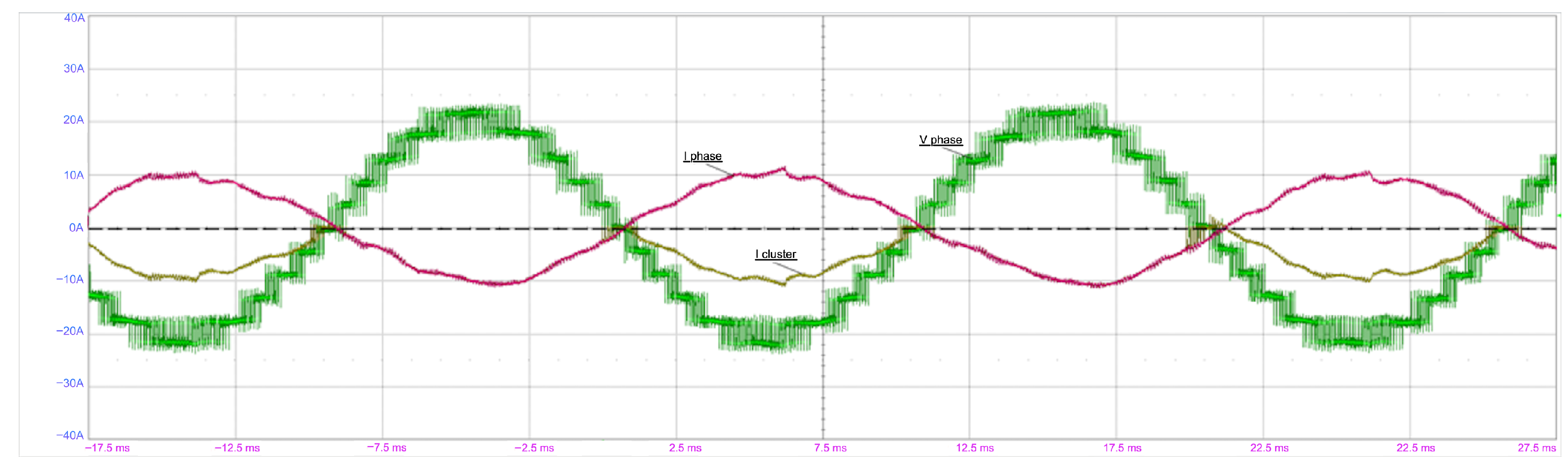
Figure 10 shows the test results for single-phase AC charging of the SmartCell clusters. The green line graph represents the incremental addition of SmartCell clusters in a stepwise manner, resulting in an increase in the charging voltage. The clusters create a partial voltage by the use of PWM. The pink line graph illustrates the sinusoidal phase charging current, which exhibits some disturbances originating from the grid, which the charging control system attempts to mitigate and provide a smooth current waveform. The cluster current, denoted as Icluster indicates the current from the first connected SmartCell cluster, which remains in phase with the charging voltage and has the same polarity all the time with no reactive power.

Non-Isolated AC Charging

Non-isolated AC charging is one of the key enablers of SmartCell as it eliminates the need for a conventional OBC, which helps to save cost, weight and increases charging efficiency. With so many benefits, it raises legitimate questions regarding ground leakage current, consumer safety, and compliance with EV charging standards [11]. SmartCell explicitly recognizes these concerns and incorporates architectural, control, and protection mechanisms designed to meet international leakage-current requirements. Primarily, the SmartCell system integrates per-cluster H-bridges for direct AC charging with internal safety overrides that can disconnect any cluster in case of abnormal electrical behavior. The design already includes continuous isolation monitoring, default by-pass, relays with fast release and bouncing time, ASIL D on main processor on the Master Board, redundant measurements for both Current and Voltage and shutdown capability through hardware-level safety overrides on each cluster’s gate drivers which are intended specifically to prevent hazardous current paths during both traction and charging operations.
The independent studies by ref. [16,17] confirms that non-isolated chargers can exhibit dangerous common-mode (CM) leakage currents if not managed. Ref. [17] shows that switching-frequency CM voltages can exceed UL 2202 touch-current limits (0.25 V-rms) at only 200 V DC link, demonstrating risks in grounding systems and potential nuisance tripping in the systems. Research by ref. [16] further demonstrate that raw non-isolated integrated chargers can produce leakage currents up to 3 A if no mitigation is applied.
However, SmartCell multilevel architecture provide effective mitigation strategies. Also, ref. [17] show that floating-filter networks combined with phase-interleaving modulation can suppress leakage by 70% and reduce touch current below 1 measurement indication unit (MIU), meeting IEC 61851-23 safety limits under all tested DC-link voltages and power levels [18]. Similarly, ref. [11] demonstrate that multilevel converters directly connected to the AC grid can maintain compliant leakage levels when appropriate inductive filtering and modulation are applied. SmartCell’s architecture inherently supports various mitigation techniques such as its multilevel CHB topology supports nearest-level modulation which naturally reduces dv/dt and CM voltage magnitude and also minimum parasitic capacitance to reduce the displacement leakage current.
Thus, when implemented together all hardware safety overrides, isolation monitoring, multilevel modulation, and CM-oriented filtering, low parasitic capacitance and advanced current controls, SmartCell becomes technically capable of meeting international leakage-current safety standards for consumer-grade charging infrastructure while retaining the efficiency benefits of non-isolated AC charging.
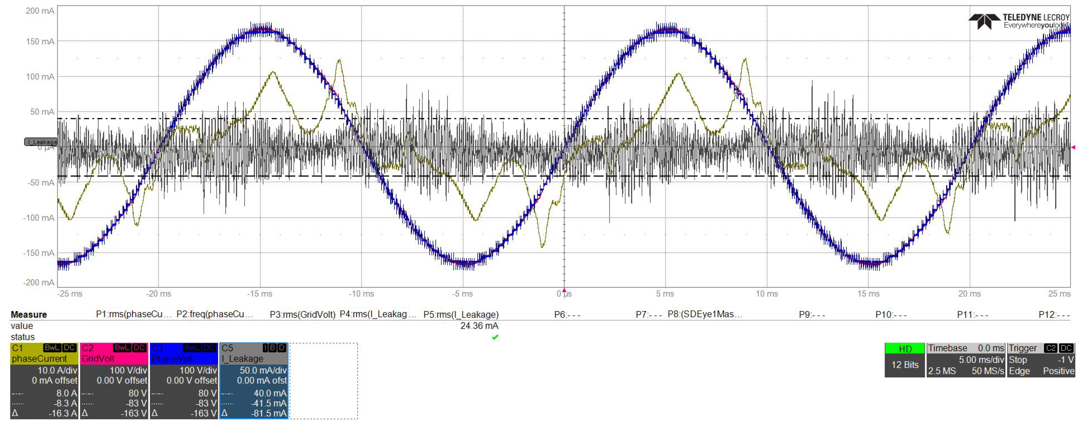
As illustrated in the Figure 11 below while performing non-isolated AC charging at grid in the industrial region with 400 Hz disturbances, the leakage current remained under 30 mA limit and did not trip the Residual Current Device (RCD). The grid voltage and phase voltage remained in sync and phase current and leakage current showed harmonics without any active control. Inclusion of active current control method will further help to handle the harmonics and improve charging efficiency.

5.3. DC/DC Operation According to Load Requirements

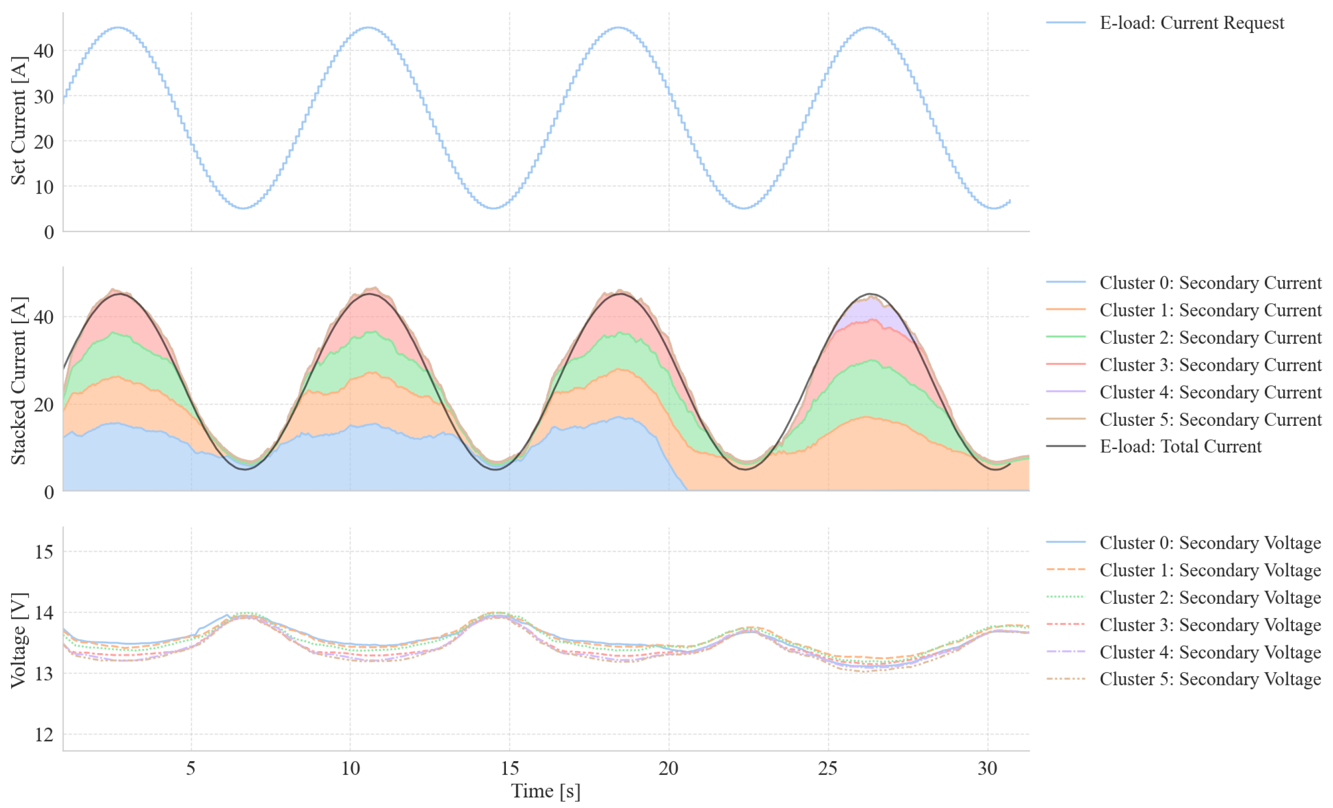
Figure 12 shows the test results for the operation of DC/DC converters subjected to a sinusoidal load. The Cluster Boards are programmed with different target voltages, where cluster 0 has the highest target voltage. At the time of minimum load, only one DC/DC converter is active to deliver power. According to Figure 12, as load increases, more Cluster Boards are engaged to provide the requested power. Another interesting benefit of this approach can be seen in the last sinusoidal peak where cluster 0 is shutting down and is replaced by cluster 4 due to high voltage dip at that instance. The target voltages for the clusters can be adjusted to equally distribute the load to various DC/DC converters according to power requirements.

5.4. Impact of Various Frequencies on Cell Durability

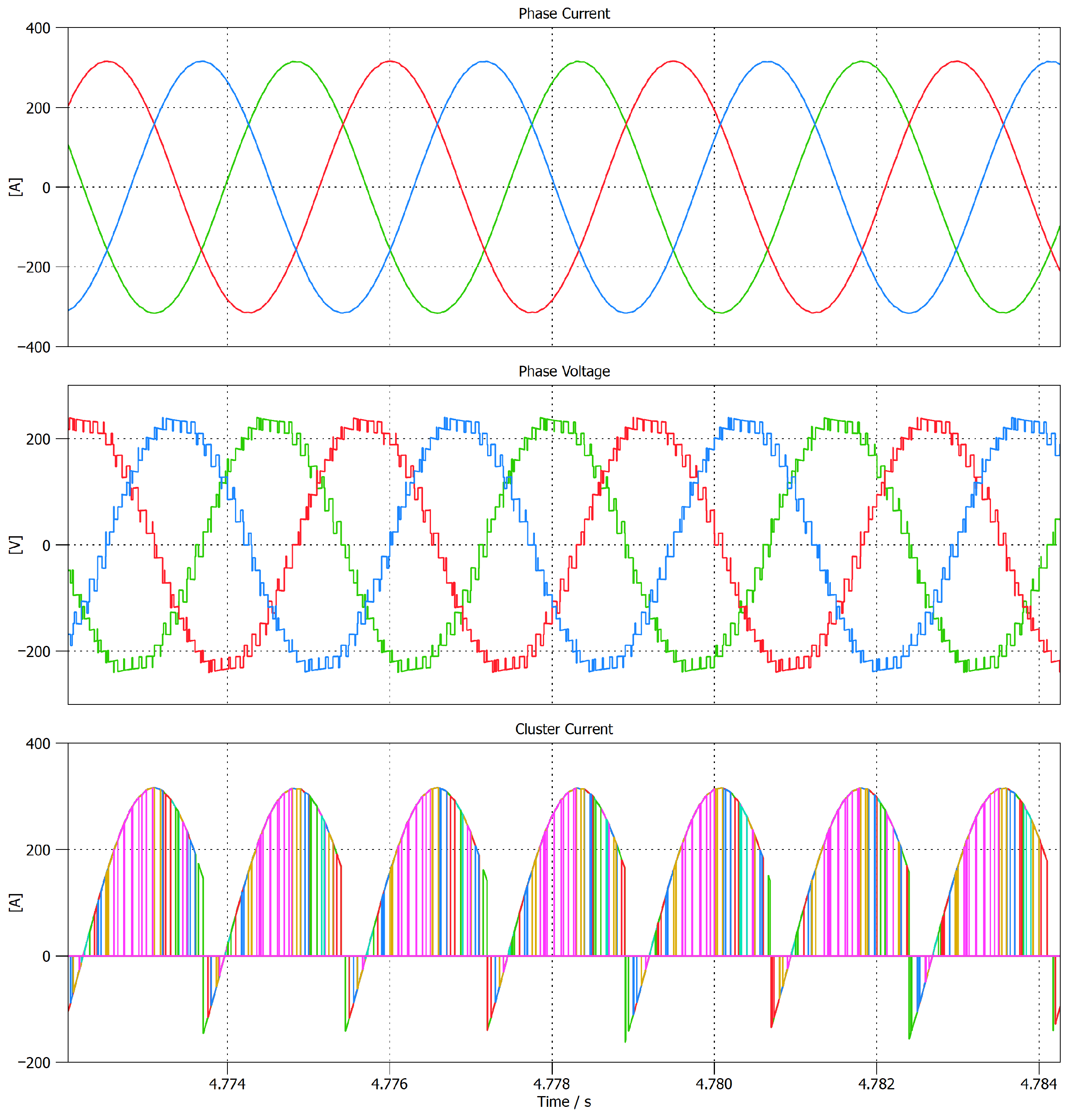
SmartCell CHB enables high-frequency pulses during both charging and traction as each cell is connected through a cascaded H-bridge multilevel inverter, allowing the pack to generate controlled pulse currents directly at the cluster level and sinusoidal phase current and voltage as shown in Figure 13. SmartCell can produce precise, high-frequency pulses and can maintain the sinusoidal shape through utilizing active switching techniques like symmetrical PWM unlike conventional EV batteries which require bulky chargers and inverters to synthesize pulsed currents. This capability allows SmartCell to apply pulse-charging profiles similar to those shown in ref. [19,20], where high-frequency pulses combined with rest intervals significantly mitigate lithium plating, reduce SEI thickening, and slow capacity fade. SmartCell research along ref. [20] demonstrates that pulse charging above 100 mHz improves durability, with some cases showing ≈38% higher capacity retention even after 300 cycles compared to constant-current charging. SmartCell can reproduce these beneficial profiles continuously during both charging and driving, enabling cells to experience the same stabilizing electrochemical conditions shown to reduce negative-electrode aging. As SmartCell switches each cell independently, it can implement optimized duty-cycles (e.g., 25%), which the study showed delivered up to 95% capacity retention, outperforming higher-duty cycles and all constant-current references. By embedding pulse-charging capability directly into the battery, SmartCell enhances cell life, safety, and fast-charging performance, while eliminating added complexity, weight, and cost from external power-electronics hardware.

5.5. System Efficiency

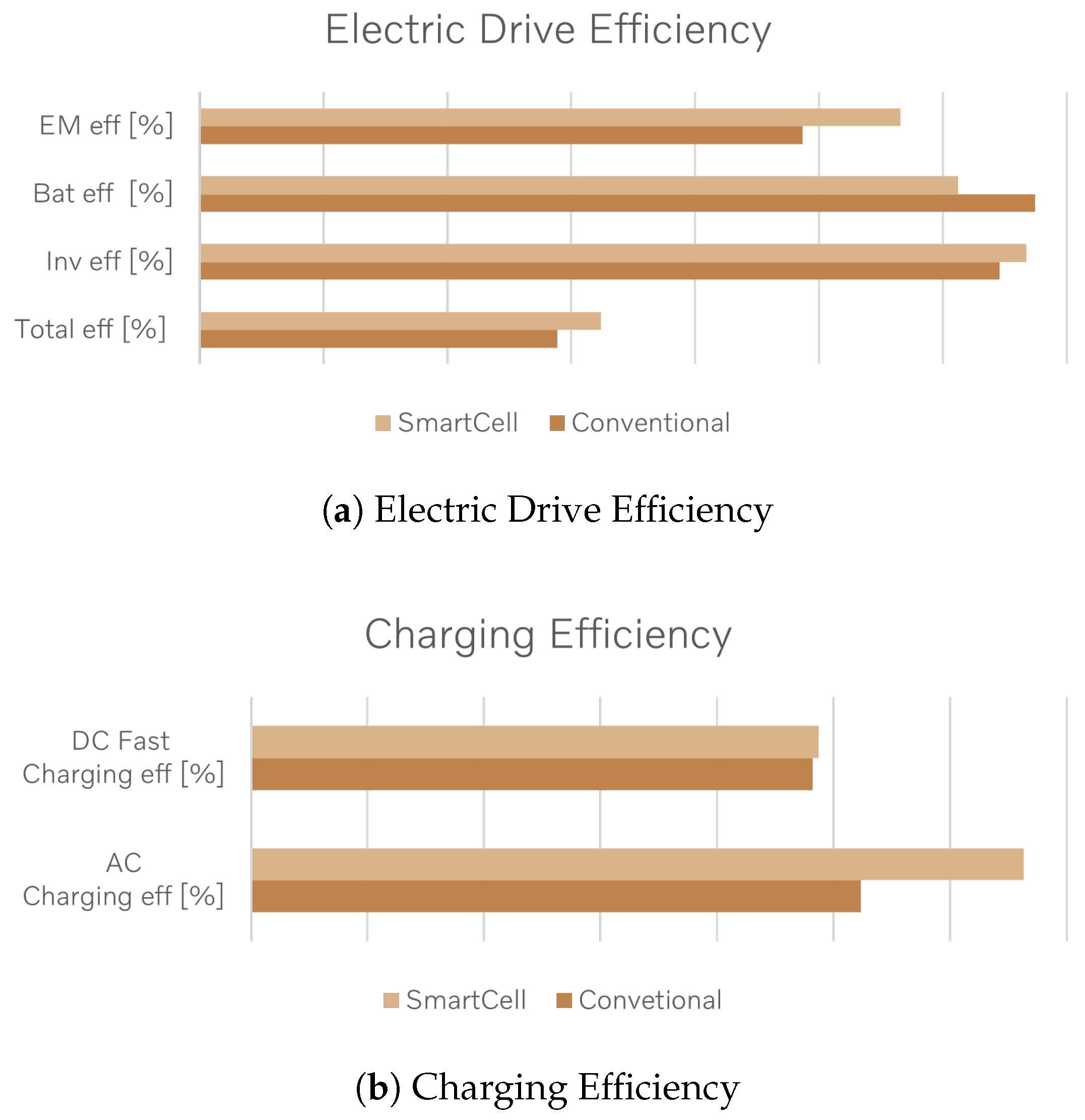
Extensive simulations have been conducted of the system to determine efficiency. It can be seen that the losses in the SmartCell system are distributed differently versus a traditional inverter-based propulsion system. Battery cell losses are increased due to higher AC currents through the cell. On the other hand, the CHB switching losses in SmartCell are reduced compared to the traditional inverter since the multi level approach allows the clusters to spend more time in pure conduction mode [21,22]. In addition, losses in electric machines are reduced due to the many conversion levels. This provides smoother AC excitation in comparison to the conventional system, which helps to reduce core losses in the electric machine and increase overall efficiency [23]. Figure 14 illustrates electric driveline efficiency simulated over WLTC for SmartCell and conventional electric driveline.
In a traditional system, there is an on-board charger which converts the AC in the grid to DC in order to charge the battery. These on-board chargers experience high losses primarily due to the inefficiencies inherent in the many stages in the AC to DC conversion process. Additionally, power factor correction (PFC) and filtering stages, which are essential for stabilizing the DC output, contribute to further inefficiencies. The SmartCell system allows connection of the battery cells directly to the grid which eliminates several stages of conversion and allows for higher efficiency than traditional system as illustrated in Figure 14.
SmartCell technology facilitates the utilization of the same switches for both traction and charging. This capability enables exceptionally high charging capacities, ranging from 100 to 200 kW, contingent upon the grid’s capacity. If cell-based multilevel systems become the automotive standard, a high-power AC infrastructure could be developed as a cost-effective complement to existing DC fast charging stations. Furthermore, SmartCell incorporates advanced current control mechanisms to internally heat the cells. This internal heating reduces the cells’ internal resistance, which typically increases as temperature decreases, thereby enhancing efficiency [24,25,26]. Traditionally, cells are heated by warming the battery coolant, which then transfers heat to the cells which is significantly less efficient due to substantial heat loss along the coolant path.

6. Discussion

The research on SmartCell-AC battery demonstrate a promising evolution in battery-integrated propulsion systems, aligning well with earlier explorations of multilevel converter topologies for electric vehicles while simultaneously extending their practical applicability towards industrialization. Previous works on modular multilevel battery (M2B) systems and cascaded H-bridge architectures have established the efficiency and scalability potential of converter-integrated batteries [27]. Volvo SmartCell confirms these theoretical expectations through system-level validation on functional hardware, particularly in propulsion, AC charging, and DC/DC operation scenarios. One of the key contributions of SmartCell is its demonstration that voltage generation through stacked clusters with CHB can effectively replace conventional inverters, onboard chargers, centralized DC/DC converters, BMS, BDU, vehicle control and power supply to its 8-in-1 solution [1]. This validates earlier hypotheses that modular multilevel topologies could unify traction and charging functionalities within the battery system [28]. The traction results show dynamic engagement of clusters based on required voltage and motor speed, reinforce the theoretical prediction that modular converters can enable finer voltage granularity and even reduce switching losses. Moreover, the improved electric machine performance attributable to multilevel excitation such as reduced core losses and smoother current waveforms, corresponds closely with observations in prior multilevel inverter studies.
The grid-charging experiments further support the hypothesis that AC charging can be performed without a dedicated onboard charger by leveraging the same CHB used for traction. The ability of clusters to synthesize sinusoidal voltages aligns with established MMC-based charger control principles. Notably, the system has high potential to achieve stable AC charging despite real-world grid disturbances, highlights robustness that theoretical models alone cannot fully capture. Similarly, the DC/DC control strategy, where converters autonomously regulate voltage based on load and target settings, showcases the redundancy and safety anticipated in distributed power conversion architectures. Such decentralized operation where each module remains functional despite communication interruptions strengthens the safety case for modularized EV powertrains [29]. The efficiency simulations illustrate that SmartCell can surpass conventional drivelines by reducing high voltage step and operating limited number of modules depending on speed and torque requirements. These findings echo previous conclusions that multilevel topologies inherently reduce switching losses. The additional observation that SmartCell enables direct, high-power AC charging introduces an important implication, hence enabling the opportunity for future charging infrastructures towards high-power AC systems if such multilevel battery architectures become widespread. SmartCell enables the use of mixed battery chemistries, allowing to balance cost and energy density by combining LFP and NMC cells within the same pack [30]. SmartCell also allows R&D work to be simplified by eliminating components, reducing interfaces and replacing hardware with software functions. Consequently, the manufacturing and assembly processes can also be simplified with fewer components and variants leading to overall shorter implementation lead-times [31,32,33].
Despite these advantages, the study identifies challenges consistent with earlier literature. The limitations in wireless communication bandwidth presents a significant challenge for real-time coordinated control of numerous distributed SmartCell clusters. Additionally, the dependency on cost-optimized Cluster Boards highlights the economic constraints associated with highly modular systems. This parallels the cost-scalability concerns previously documented in MMC-based EV architectures. Safety considerations especially regarding non-isolated AC grid charging also remain an important area requiring further validation. The system can witness capacitor-voltage ripple and circulating currents which might lead to over sizing of capacitors or inductors and increases converter volume and losses. The cells also witness higher losses due to high-frequency ripple currents compared to two-level inverters [34]. Future research includes investigation of enhanced wireless communication and control schemes such as integrating ultra-wideband or optical signalling for higher reliability and bandwidth [35]. The system safety and safe state evaluations are of high importance for further validation of the SmartCell. Finally, experimental validation in full-vehicle prototypes fleets will be essential to assess drivetrain NVH, thermal propagation, long-term durability, and homologation-related requirements.

7. Conclusions

SmartCell introduces a novel and efficient technology to control the electric propulsion system, with the potential to become an industry standard. It offers significant benefits to automotive companies by simplifying the driveline and reducing the number of components, streamlining the supply chain with large volumes of identical components, and providing customers with high driveline and charging efficiency at a lower cost. SmartCell provides further advantages to the customers such as extended range, faster and more efficient charging, high redundancy, increased space, and lighter vehicles. However, there are several challenges to be addressed or validated to harness all the advantages of this novel AC battery technology. The limited bandwidth of the wireless system can constrain control of the cluster which we are trying to eliminate through on-going development of an advanced control system. SmartCell’s ability to connect the high voltage system directly to the grid without intermediate isolation could lead to current leakage to the ground. Therefore, extensive simulation and physical testing are on-going to ensure no leakage current occurs with non-isolated grid charging. Despite the system’s simplicity in terms of number of different components, the cost of numerous Cluster Boards becomes a critical factor in the overall system cost. The cost of power MOSFETs, which constitute a significant portion of the Cluster Boards cost, must be further optimized along with the entire Cluster Board through innovation, simplification and integration. At Volvo, our purpose is to provide freedom to move in a personal, sustainable and safe way. Hence, keeping that in mind, we are working further to make SmartCell, the most sustainable, safe, efficient and cost-effective electric driveline solution.

8. Patents

The set of granted patents attributed to Volvo Cars inventors reflects a coherent technological trajectory toward integrated, intelligent, and multifunctional battery systems. The patent Intelligent Battery Device and Battery System introduce a battery cell capable of producing positive, negative, or zero output voltage via an integrated H-bridge and control electronics [36]. This transforms each cell into a controllable power-electronic unit, enabling functions normally performed by external traction inverters and DC/DC converters. The concept positions the battery itself as an active AC power source, forming the basis for multi-level conversion approaches consistent with the SmartCell methodology. The patents focus on cell-level intelligence and thermal conditioning, most notably Electric Vehicle Battery System Control Strategy Incorporating Active Cell Temperature Balancing [37]. This invention establishes a control protocol capable of selectively heating cold cells through controlled current circulation between cell subsets. The patent directly addresses long-standing battery management challenges, especially regarding cold-temperature performance and cell-to-cell variation.
The advancements extend further through patents describing enhanced power conversion autonomy. For example, Integrated Alternating Current and Direct Current Supply in a Battery and Active Balancing at Standstill Facilitating Direct Current Supply [38] reduce external converter dependencies by integrating both AC generation and DC supply capabilities directly at the cell or cluster level. These inventions advance the industry trend toward component consolidation, potentially reducing weight, cost, and conversion losses which are the key performance drivers in modern EV design. The patent Isolation resistance monitoring for high voltage systems presents a system that can measure insulation resistance between high-voltage components and the vehicle chassis for both the onboard SmartCell battery system and an external DC charging source [39]. This dual-monitoring capability increases safety, particularly during DC charging, when the vehicle and charger become galvanically connected. The system performs structured diagnostic sequences by selectively energizing buses at safe voltage levels and opening or closing specific contactor, allowing it to pinpoint faults in components such as harnesses, busbars, charging inlets, or traction motors. By identifying the exact fault location, the invention can block AC charging, DC charging, or drivetrain operation as needed, ensuring safe vehicle behavior and simplifying service diagnostics. Together, these patents contribute a layered architecture of intelligent power modulation, electric machine control [40], thermal and health-aware control, embedded AC/DC power conversion, and distributed auxiliary power pathways. The patent Intelligent Battery Cell describes SmartCell architecture that transforms individual or group of lithium ion cells into actively controlled power-electronic clusters [41]. Each SmartCell cluster integrates a dedicated circuit board, sensors, and a H-bridge to provide both AC and isolated DC power supply. This enables every cell to connect, disconnect, or reverse polarity on request. The invention enables load sharing, reactive charging protection, and PWM modulation at the cell level which improves efficiency, redundancy, and safety. Overall, the patent redefines the battery from a passive energy source into an active, modular inverter system capable of both energy storage and real time power conversion. Overall, the granted patents represent a foundational intellectual property framework for next-generation EV battery systems that integrate propulsion, charging, and power management into a unified and intelligent architecture.

Author Contributions

Conceptualization, J.F., M.E., A.P.S., J.B. and T.L.; Methodology, J.F. and A.P.S.; Validation, J.F.,A.P.S. and T.L.; Formal analysis, A.P.S.; Resources, T.L. and J.B.; Data curation, J.F., A.P.S., M.E., J.B. and T.L.; Writing—Original draft, J.F. and A.P.S.; Writing—review and editing, A.P.S., M.E., T.L. and J.B.; Discussion, A.P.S.; supervision, J.F. and T.L.; Project administration, J.F. All authors have read and agreed to the published version of the manuscript.

Funding

This research received no external funding.

Data Availability Statement

The original contributions are included in the article. More information can be found through the granted patents [36,37,38,39,40,41].

Acknowledgments

We acknowledge the contributions made by the SmartCell project team members and supporting contributors at Volvo Cars.

Conflicts of Interest

The authors are employed at Volvo Car Corporation and all research is done at the company. The authors declare no conflict of interest.

Abbreviations

The following abbreviations are used in this manuscript:
ACAlternating Current
ASILAutomotive Safety Integrity Level
BDUBattery Disconnect Unit
BMSBattery Monitoring System
CANController Area Network
CHBCascaded H-Bridge
CMCommon Mode
DCDirect Current
DC/DCDirect Current to Direct Current Converter
EMIElectromagnetic Interference
EVElectric Vehicle
HVHigh Voltage
LFPLithium Iron Phosphate
LINLocal Interconnect Network
M2BModular Multilevel Battery
MCUMain Controller Unit
MIUMeasurement Indication Unit
MMCModular Multilevel Converter
NMCNickel Manganese Cobalt
PWMPulse-Width Modulation
R&DResearch and Development
SOHState-of-Health
SOCState-of-Charge
WLTCWorldwide Harmonized Light Vehicle Test Cycle

References

  1. Forssell, J.; Ekström, M.; Singh, A.P.; Larsson, T.; Björkholtz, J. Volvo SmartCell: A New Multilevel Battery Propulsion and Power Supply System. In Proceedings of the 38th International Electric Vehicle Symposium and Exhibition (EVS38), Gothenburg, Sweden, 15–18 June 2025; WEVA: Washington, DC, USA, 2025; pp. 1–11. Available online: https://evs38-program.org/images/Proceedings (accessed on 1 April 2025).
  2. Eaker, M. 48V Automotive Systems: Why Now? Texas Instruments: Dallas, TX, USA, 2025; Available online: https://www.ti.com/lit/wp/slyy243/slyy243.pdf (accessed on 1 March 2025).
  3. Josefsson, O. Investigation of a Multilevel Inverter for Electric Vehicle Applications. Ph.D. Thesis, Chalmers University of Technology, Göteborg, Sweden, 2015. [Google Scholar]
  4. Helling, F.; Glück, J.; Singer, A.; Weyh, T. Modular multilevel battery (M2B) for electric vehicles. In 18th European Conference on Power Electronics and Applications (EPE’16 ECCE Europe), Karlsruhe, Germany, 5–9 September 2016; IEEE: New York, NY, USA, 2016; pp. 1–9. [Google Scholar] [CrossRef]
  5. Theliander, O.; Kersten, A.; Kuder, M.; Grunditz, E.; Thiringer, T. LiFePO4 Battery Modeling and Drive Cycle Loss Evaluation in Cascaded H-Bridge Inverters for Vehicles. In IEEE Transportation Electrification Conference and Expo (ITEC), Detroit, MI, USA, 19–21 June 2019; IEEE: New York, NY, USA, 2019; pp. 1–7. [Google Scholar] [CrossRef]
  6. Road Vehicles—Functional Safety—Part 1: Vocabulary. International Organization for Standardization: Geneva, Switzerland, 2018. Available online: https://www.iso.org/standard/43464.html (accessed on 5 March 2025).
  7. Xiao, Q.; Yu, H.; Jin, Y.; Jia, H.; Mu, Y.; Liu, H.; Li, W.; Teodorescu, R.; Blaabjerg, F. A Novel Fault-Tolerant Operation Approach for CHB Converter-Based Battery Energy Storage Systems to Avoid Overcharge. IEEE Trans. Ind. Electron. 2025, 72, 5497–5506. [Google Scholar] [CrossRef]
  8. Hu, J.; Ma, J.; Shah, A.; Hao, L.; Yang, J.; Tian, M.; Ismail, P.; Wei, H.; Ozturk, Y.; Shen, B.; et al. Impact of Magnetic Substrate on Dynamic Loss and Magnetization Loss of HTS Coated Conductors. IEEE Trans. Appl. Supercond. 2022, 32, 8200405. [Google Scholar] [CrossRef]
  9. United Nations Economic Commission for Europe. Uniform Provisions Concerning the Approval of Vehicles with Regard to Electromagnetic Compatibility; ECE Regulation No. 10, Revision 5, United Nations Economic Commission for Europe: Geneva, Switzerland, 2014. [Google Scholar]
  10. Balachandran, A. Design, Modulation, and Control of Battery-Integrated Modular Multilevel Converters for Automotive Applications; Linköping University: Linköping, Sweden, 2025. [Google Scholar] [CrossRef]
  11. Tresca, G.; Zanchetta, P. AC Direct Charging for Electric Vehicles via a Reconfigurable Cascaded Multilevel Converter. Energies 2024, 17, 2428. [Google Scholar] [CrossRef]
  12. Yang, S.; Zhou, X.; Zhou, S.; Gao, Z.; Cui, H.; Hua, Y.; Li, Q.; Chen, F. Advanced Wireless Battery Management System for Electric Vehicles: Design, Application and Perspective. Automot. Innov. 2025, 8, 421–442. [Google Scholar] [CrossRef]
  13. Cao, Z.; Gao, W.; Fu, Y.; Mi, C. Wireless Battery Management Systems: Innovations, Challenges, and Future Perspectives. Energies 2024, 17, 3277. [Google Scholar] [CrossRef]
  14. Xiao, L.; Johansson, M.; Hindi, H.; Boyd, S.; Goldsmith, A. Joint Optimization of Wireless Communication and Networked Control Systems. In Switching and Learning in Feedback Systems; Murray-Smith, R., Shorten, R., Eds.; Springer: Berlin/Heidelberg, Germany, 2005; Volume 3355, pp. 248–272. [Google Scholar]
  15. Mager, F.; Baumann, D.; Herrmann, C.; Trimpe, S.; Zimmerling, M. Scaling Beyond Bandwidth Limitations: Wireless Control with Stability Guarantees under Overload. ACM Trans. Cyber-Phys. Syst. 2022, 6, 1–30. [Google Scholar] [CrossRef]
  16. Shao, X.; Zhang, Q.; Wei, Z.; Li, H. A Method for Suppressing Leakage Current of Non-isolated Integrated On-board EV Battery Charger. Chin. J. Electr. Eng. 2024, 10, 47–59. [Google Scholar] [CrossRef]
  17. Zhang, X.; Yang, G.; He, X.; Elshaer, M.; Perdikakis, W.; Li, H.; Yao, C.; Wang, J.; Zou, K.; Xu, Z.; et al. Leakage Current Issue of Non-Isolated Integrated Chargers for Electric Vehicles. In 2018 IEEE Energy Conversion Congress and Exposition (ECCE); IEEE: New York, NY, USA, 2018. [Google Scholar] [CrossRef]
  18. IEC 61851-23:2014; Electric Vehicle Conductive Charging System—Part 23: DC Electric Vehicle Charging Station. IEC: Geneva, Switzerland, 2014.
  19. Frenander, K.; Thiringer, T. Low Frequency Influence on Degradation of Commercial Li-Ion Battery. Electrochim. Acta 2023, 462, 142760. [Google Scholar] [CrossRef]
  20. Frenander, K.; Jutsell Nilsson, D.; Thiringer, T. Extending Battery Lifetime by Pulsed Charging. npj Clean Energy 2026, 2, 4. [Google Scholar] [CrossRef]
  21. Chang, F.; Ilina, O.; Lienkamp, M.; Voss, L. Improving the Overall Efficiency of Automotive Inverters Using a Multilevel Converter Composed of Low Voltage Si MOSFETs. IEEE Trans. Power Electron. 2019, 34, 3586–3602. [Google Scholar] [CrossRef]
  22. Sachs, C.; Neuburger, M. A Data-Based Review of Battery Electric Vehicle and Traction Inverter Trends. In IECON 2025—51st Annual Conference of the IEEE Industrial Electronics Society; IEEE: New York, NY, USA, 2025. [Google Scholar] [CrossRef]
  23. Rasilo, P.; Salem, A.; Abdallh, A.; De Belie, F.; Dupré, L.; Melkebeek, J.A. Effect of Multilevel Inverter Supply on Core Losses in Magnetic Materials and Electrical Machines. IEEE Trans. Energy Convers. 2015, 30, 736–744. [Google Scholar] [CrossRef]
  24. Lemssaddak, S.; Hakam, Y.; Elmahjoub, A.A.; Tabaa, M.; Zegrari, M. Examining the Current Advancements in Intelligent Multilevel Inverters for Electric Vehicle Charging Applications. Sci. Afr. 2025, 29, e02799. [Google Scholar] [CrossRef]
  25. Ji, Y.; Wang, C.Y. Heating strategies for Li-ion batteries operated from subzero temperatures. Electrochim. Acta 2013, 107, 664–674. [Google Scholar] [CrossRef]
  26. Liu, Y.; Liao, Y.G.; Lai, M.-C. Effects of Depth-of-Discharge, Ambient Temperature, and Aging on the Internal Resistance of Lithium-Ion Battery Cells. In International Conference on Electrical, Computer and Energy Technologies (ICECET), Cape Town, South Africa, 9–10 December 2021; IEEE: New York, NY, USA, 2021; pp. 1–5. [Google Scholar] [CrossRef]
  27. Hren, A.; Truntić, M.; Mihalič, F. A Survey on the State-of-the-Art and Future Trends of Multilevel Inverters in BEVs. Electronics 2023, 12, 2993. [Google Scholar] [CrossRef]
  28. Shi, B.; Ramones, A.I.; Liu, Y.; Wang, H.; Li, Y.; Pischinger, S.; Andert, J.L. A Review of Silicon Carbide MOSFETs in Electrified Vehicles: Application, Challenges, and Future Development. IET Power Electron. 2023, 16, 2103–2120. [Google Scholar] [CrossRef]
  29. Poorfakhraei, A.; Narimani, M.; Emadi, A. A Review of Multilevel Inverter Topologies in Electric Vehicles: Current Status and Future Trends. IEEE Open J. Power Electron. 2021, 2, 155–170. [Google Scholar] [CrossRef]
  30. GM Authority. Mixed Chemistry EV Battery Packs (NMC + LFP). 2025. Available online: https://gmauthority.com/blog/2025/01/gm-is-working-on-mixed-chemistry-ev-battery-packs/ (accessed on 21 February 2026).
  31. Ronanki, D.; Williamson, S.S. Modular Multilevel Converters for Transportation Electrification: Challenges and Opportunities. IEEE Trans. Transp. Electrif. 2018, 4, 399–407. [Google Scholar] [CrossRef]
  32. Pongnot, G.; Mayet, C.; Labrousse, D. Loss Distribution in an Electric Vehicle Traction Chain using a Cascaded H-Bridge Inverter with Integrated Battery. In PCIM Europe 2023; International Exhibition and Conference for Power Electronics, Intelligent Motion, Renewable Energy and Energy Management, Nuremberg, Germany, 9–11 May 2023; VDE: Berlin, Germany, 2023. [Google Scholar] [CrossRef]
  33. McKinsey Center for Future Mobility. The Battery Chemistries Powering the Future of Electric Vehicles; McKinsey: Berlin, Germany, 2024; Available online: https://www.mckinsey.com/industries/automotive-and-assembly/our-insights/the-battery-chemistries-powering-the-future-of-electric-vehicles (accessed on 20 February 2026).
  34. Balachandran, A. Battery Integrated Modular Multilevel Converter Topologies for Automotive Applications; Linköping University: Linköping, Sweden, 2023. [Google Scholar] [CrossRef]
  35. Porsche Engineering. Multi-Level Inverter—Turning DC into AC (MMSPC). 2025. Available online: https://newsroom.porsche.com/en/2025/innovation/porsche-engineering-multi-level-inverter-dc-ac-38890.html (accessed on 30 March 2025).
  36. Forssell, J. Intelligent Battery Device and Battery System. U.S. Patent 11,874,331, 16 January 2024. [Google Scholar]
  37. Singh, A.P.; Forssell, J.; Ekström, M. Electric Vehicle Battery System Control Strategy Incorporating Active Cell Temperature Balancing. U.S. Patent 12,479,334, 25 November 2025. [Google Scholar]
  38. Forssell, J. Active Balancing at Standstill Facilitating Direct Current Supply. U.S. Patent 11,973,199, 30 April 2024. [Google Scholar]
  39. Al, F.; Larsson, T. Isolation Resistance Monitoring for High Voltage Systems. U.S. Patent 12,123,904 B2, 22 October 2024. [Google Scholar]
  40. Sjöstrand, S.; Koit, K.; Singh, A.P.; Thiringer, T.; Ekström, M. High Speed Control of Motor Current in a Distributed Inverter System. U.S. Patent 12,214,696 B1, 4 February 2025. [Google Scholar]
  41. Ekström, M. Intelligent Battery Cell. U.S. Patent 12,301,037 B2, 13 May 2025. [Google Scholar]
Figure 1. Overview of SmartCell battery pack.
Wevj 17 00190 g001
Figure 2. Main components of the Cluster Board.
Wevj 17 00190 g002
Figure 3. Master Board block diagram.
Wevj 17 00190 g003
Figure 4. SmartCell schematic.
Wevj 17 00190 g004
Figure 5. Current path used for canceling electromagnetic interference (EMI).
Wevj 17 00190 g005
Figure 6. Communication protocol.
Wevj 17 00190 g006
Figure 7. Power control interface.
Wevj 17 00190 g007
Figure 8. DCDC control.
Wevj 17 00190 g008
Figure 9. Cluster usage during traction.
Wevj 17 00190 g009
Figure 10. AC charging.
Wevj 17 00190 g010
Figure 11. SmartCell non-isolated AC Charging.
Wevj 17 00190 g011
Figure 12. DC/DC load response.
Wevj 17 00190 g012
Figure 13. SmartCell Cluster and Phase Output.
Wevj 17 00190 g013
Figure 14. SmartCell vs. conventional system simulated efficiency.
Wevj 17 00190 g014
Disclaimer/Publisher’s Note: The statements, opinions and data contained in all publications are solely those of the individual author(s) and contributor(s) and not of MDPI and/or the editor(s). MDPI and/or the editor(s) disclaim responsibility for any injury to people or property resulting from any ideas, methods, instructions or products referred to in the content.