1. Introduction
Insulation structures are widely used in the field of power equipment, and their performance significantly affects the safe and stable operation of motors [
1,
2]. In the field of electric vehicle (EV) drive, permanent magnet synchronous motors (PMSMs) and induction motors (IMs) are currently the two most widely used types of motors. The realization of their high performance and high reliability both rely on the integrity of the stator winding insulation system.
Permanent magnet synchronous motors, with their advantages of high power density and high efficiency, have become the mainstream choice for modern electric vehicles. To achieve higher performance, high slot fullness rate and short end winding designs represented by flat copper wire (hairpin type) windings are widely adopted. This design not only enhances efficiency but also, due to its rigid structure, subjects the end windings to higher periodic mechanical stress under the action of complex electromagnetic forces [
3,
4]. Meanwhile, induction motors still have a place in commercial vehicles and high-performance drive applications due to their robustness, durability and controllable cost. Its stator windings are also confronted with complex electrical and mechanical stress effects caused by high-frequency pulse width modulation (PWM) power supply, sudden load changes, and potential resonance [
5,
6]. In the process of manufacturing for stator insulation, process treatment and long-term service, it is inevitably to cause the initial damage in the insulation layer of stator end-windings. In addition, during the service of the motor, the end winding insulation system is frequently subjected to the complex multi-physical fields such as magnetic, electric, thermal and mechanic coupling stress. Due to aging, the internal crack defects of the ground insulation increase and gradually evolve, resulting in large damage, causing the dielectric properties of the insulation and reducing the residual breakdown voltage intensity, even producing insulation breakdown short circuit fault [
7,
8].
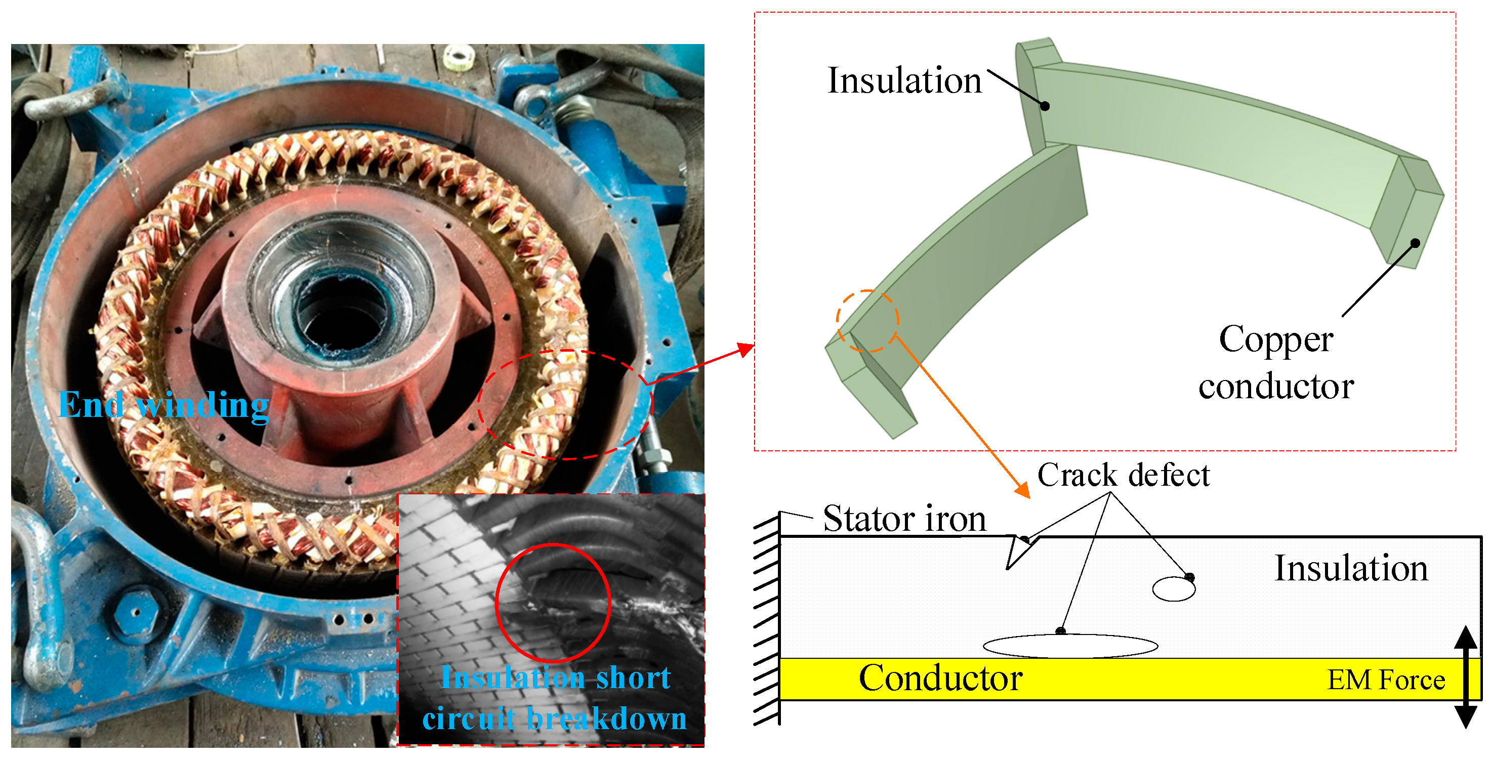
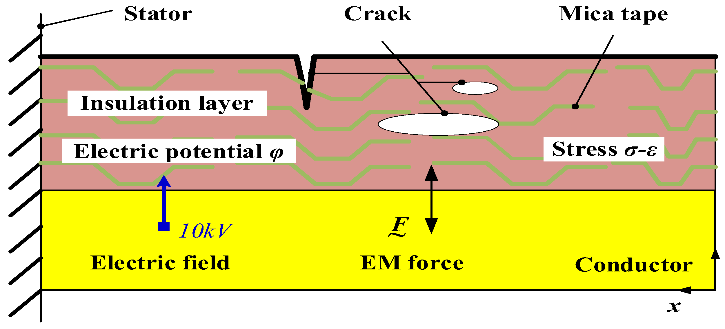
Figure 1 shows the stator end-winding and ground insulation with crack defects.
Most of the existing research focus on the electrical damage mechanism and variation characteristics of insulation [
9,
10,
11,
12,
13,
14,
15,
16], and there are few studies on the mechanical damage mechanism of ground insulation for motor end-winding. Despite the critical importance of end-winding insulation, current diagnostic and preventive approaches present significant limitations that this work aims to overcome. On the diagnosis front, established techniques such as partial discharge (PD) monitoring and vibration analysis are largely reactive or lack specificity. PD detection, while effective in identifying advanced internal defects, often provides a clear signal only after substantial electrical degradation has occurred, offering limited warning for incipient mechanical crack propagation. Similarly, global vibration monitoring often lacks the specificity to distinguish insulation cracking from other mechanical sources within the complex vibration spectrum of an operating motor.
On the design and prevention front, common practice relies heavily on empirical safety factors and material tests conducted under isolated stress conditions (e.g., pure electrical aging or mechanical fatigue). These approaches fail to capture the synergistic, coupled evolution of damage under the true multi-physical field environment in service. A pronounced gap exists in predictive tools capable of quantitatively simulating how a mechanical crack initiates and propagates, and how this process dynamically interacts with and distorts the local electric field to precipitate dielectric failure. This lack of mechanistic understanding hinders the transition from experience-based design to predictive design and accurate remaining life assessment for insulation systems, particularly under the demanding profiles of EV drive motors. Recently, in the field of mechanics, many scholars have conducted extensive research on crack propagation [
17,
18]. Also, the finite element method (FEM) is often used for simulating the initial crack propagation in welded joints [
19] and the interaction between cracks in brittle solids [
20]. Employing FEM may increase the complexity of the crack model. However, in the fracture phase field method, cracks are represented by continuous phase field variables, which makes the natural propagation and branching of cracks easier to handle.
In this paper, the insulation at the end region of the motor stator is equivalent to a cantilever beam model, where the fracture phase field theory is employed to derive the evolution equations of insulation damage. The distribution of stress and strain around the crack damage of insulation are calculated. The propagation behaviors of insulation crack damage under the dynamic electromagnetic forces from the winding conductors are analyzed, as well as the coupling changes in electric potential and electric damage are determined. This work provides a new theoretical framework and numerical tool for understanding the fundamental physics of insulation failure, which is expected to inform the development of mechanism-based condition assessment and contribute to the reliability-driven design of next-generation EV motor insulation systems.
2. Evolution Model of Electromechanical Damage
2.1. Variable Definition of Electromechanical Damage
Based on phase field theory, the development law of crack propagation in insulation can be obtained in space, and a phase field variable
d(
x) related to damage displacement [
21], given by
where
x is the current length of the crack damage,
is the initial length of the crack,
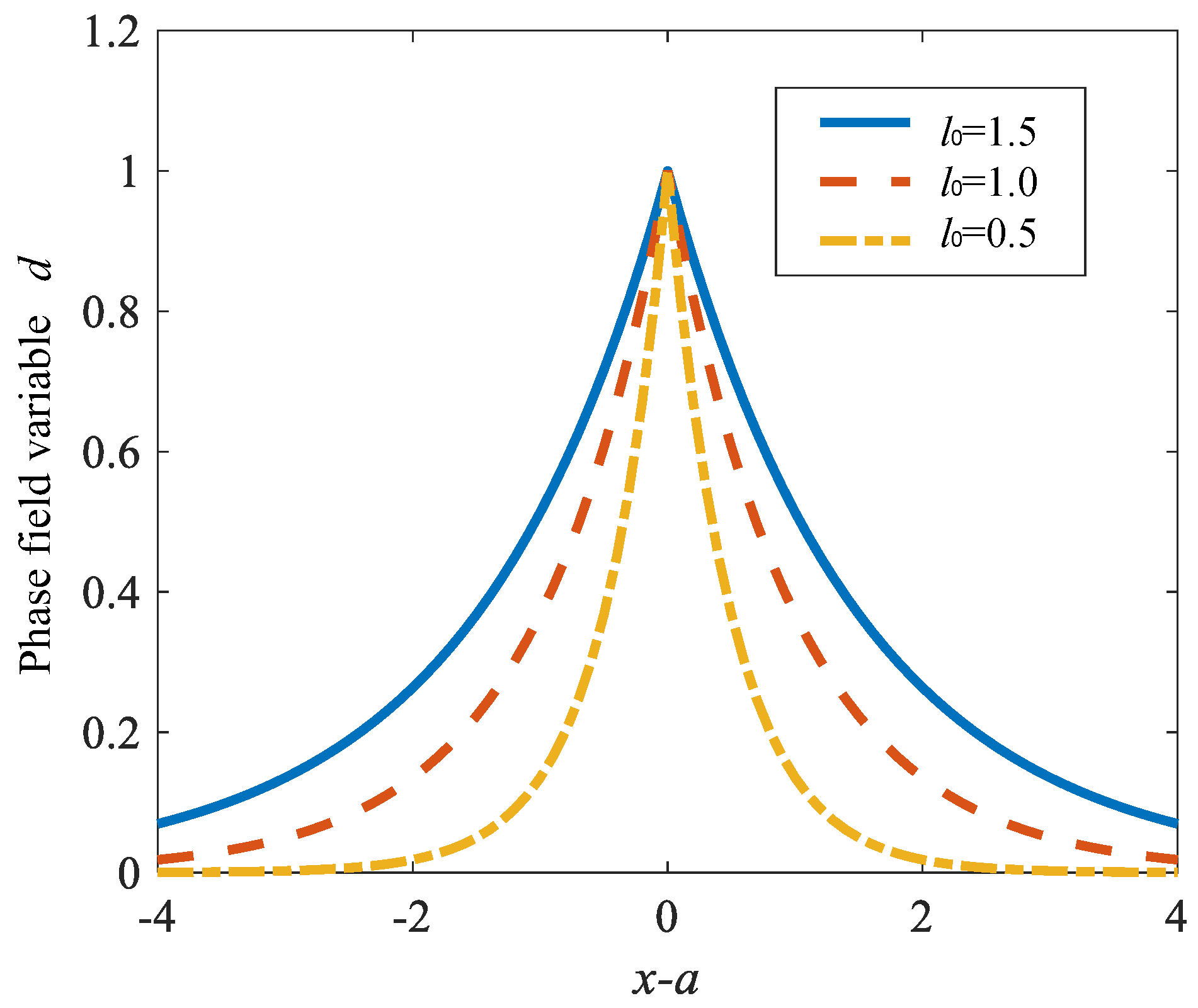
l0 is the parameter that controls the length of damage propagation and the degree of crack dispersion, where the larger the value, the larger the dispersion area of the crack.
Figure 2 shows the phase field values corresponding to different
l0.
The phase field variable
is a spatially continuous function. Its core concept is to regularize a sharp, discrete crack surface into a continuous damage field with a diffuse width [
21]. Here,
represents intact material, and
represents complete fracture. The exponential decay form given in Equation (1) is a common function satisfying the one-dimensional static crack solution in phase-field theory, where the characteristic length scale
controls the width of the damage diffusion zone [
22]. A smaller
leads to a more localized damage field, better approximating a sharp crack; however, its lower limit is constrained by the mesh size
, requiring
to ensure solution accuracy. The fundamental advantage of this regularization method is its natural handling of crack initiation, propagation, branching, and merging without the need to track complex crack geometry or perform remeshing. This is particularly suitable for analyzing potential complex crack networks in composite insulation.
For the ground insulation of motors, the crack propagation will change the distribution of electric potential in the insulation. Here, an electrical damage variable is defined to quantitatively describe the degree of deterioration of electrical properties of insulation, which is given by
where
φ0(
r) is the initial electric potential, and
φt(
r) is the deteriorated electric potential.
r is the coordinate vector.
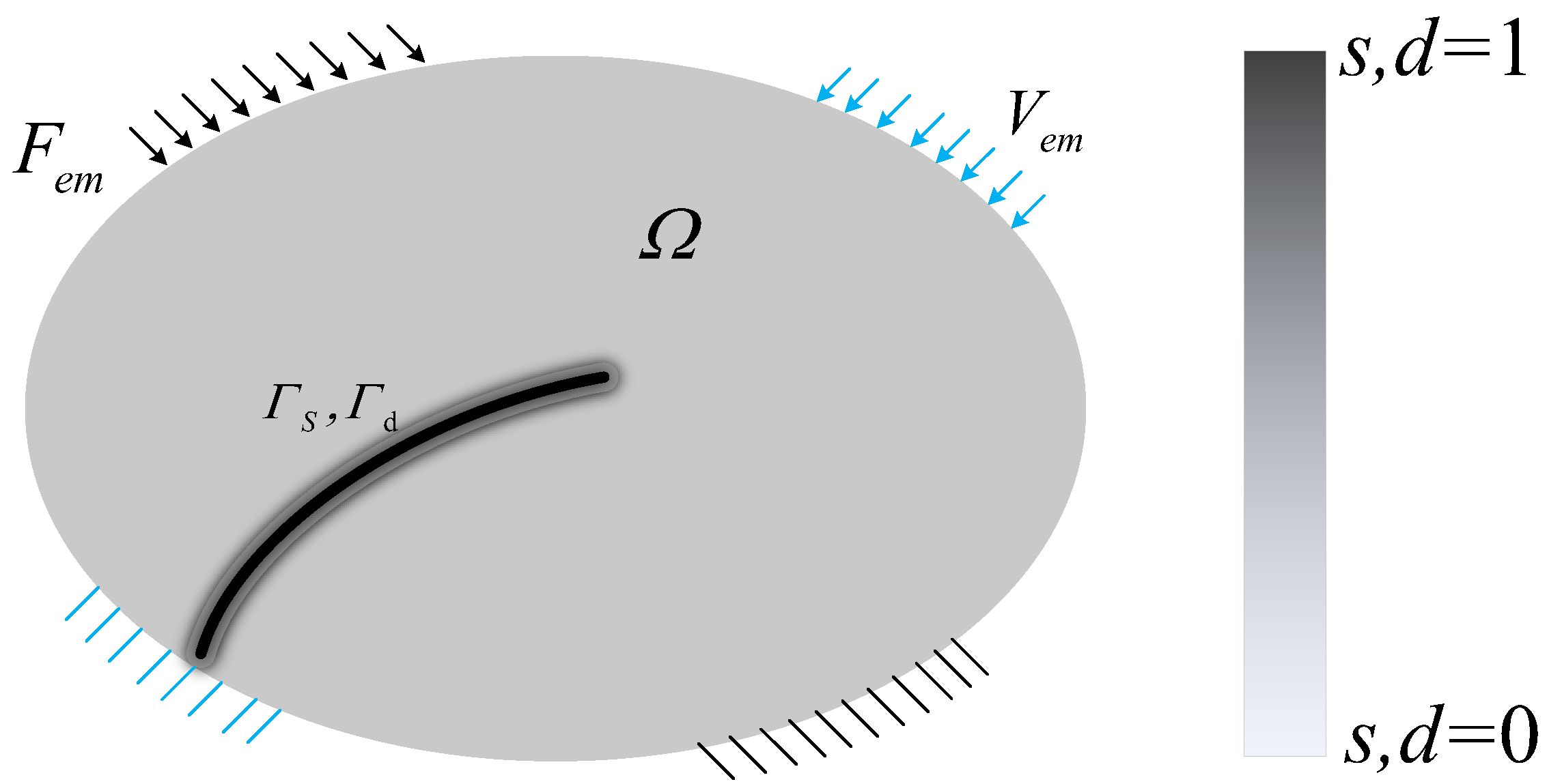
In fact, the change in phase field variables is related to the degree of damage caused by the propagation of insulation cracks in the motor, which can be obtained through the properties of the phase field model. Then, it can be understood that the insulation is health when the phase field variable
d(
x) is equal to 0, and the insulation layer is completely broken when the phase field variable
d(
x) is equal to 1. Similarly, when
s(
r) is equal to 1, the insulating layer is completely broken down, and when
s(
r) is equal to 0, the insulation is health, as shown in
Figure 3. The values between 0 and 1 indicate that the insulation is subjected to different degrees of electrical damage.
2.2. Fracture Energy of Insulation Damage
The Francfort–Marigo variation principle was originally proposed for the crack model, which is the basis of the phase field method. In this variation principle, the overall potential energy of the structure includes not only the strain potential energy, the external force potential energy and the fracture energy consumed by the crack surface. That is, the generation of the crack surface must be accompanied by certain energy dissipation. In the solution region with cracks, the total potential energy of the system is obtained as
where
is the strain potential energy of insulation,
is the external force potential energy, and
is the fracture energy.
The weak form of the governing equation of the external potential energy can be expressed as
where
u is the displacement field vector of insulation,
b is the body force density, and
h is the surface boundary traction force.
The fracture energy
Wd is the product of the critical energy release rate
GC and the discrete crack area function
A(
d) [
22], which is expressed as
The phase-field fracture model based on the Francfort–Marigo variational principle treats fracture as an energy minimization problem [
22]. The total potential energy
(Equation (3)) comprises the elastic strain energy
, the work of external forces, and the fracture energy
. The fracture energy density function
is a hallmark of the phase-field method, quantifying the energy required to create a unit crack area. The term
in Equation (5) integrates this density over the domain
, approximating the surface area of a discrete crack. The degradation function
in Equation (6) reduces the load-bearing stiffness of the material as damage evolves (
). The small parameter
prevents the global stiffness matrix from becoming singular, ensuring numerical stability.
Where
GC is the critical energy release rate. To reflect the reduction in strain energy caused by the existence of damage, the loss function
is introduced as
where
k is an additional parameter to avoid numerical singularity when
d(
x) = 1. Here,
k is far less than 1 (
k = 1 × 10
−6). In addition, in order to prevent the crack from self-healing, a historical variable
H is introduced to ensure that the strain energy density [
23], which is given by
where
ψ(
ω) is the strain energy density function,
ω is the strain and related to the displacement of the insulation. Then, the corresponding strain potential energy may be obtained as
where Ω is the solution domain as shown in
Figure 3.
2.3. Electric Potential Determination
The propagation of the crack may cause the distribution of the electric potential in the insulation to change. Here, the Poisson equation is used to calculate the change in the electric potential on the insulation during the crack propagation, which are given as
where
r is the position vector in the space,
ρ is the charge density function,
D is the electric flux density,
E is the electric field strength,
ε0 and
ε(
r) are the dielectric constants of air and insulation, respectively.
Crack propagation within insulating materials alters not only the mechanical fields but also the boundary conditions for the electric field distribution. In intact dielectric, the electric potential satisfies Laplace’s equation . When a crack forms, its interior can be treated as a cavity filled with air (dielectric constant ). To handle this abrupt change in material property within a unified phase-field framework, an interpolation method dependent on the phase-field variable is introduced. The effective dielectric constant is expressed as , where is a monotonically decreasing function, potentially similar to the mechanical degradation function . Consequently, Poisson’s equation in Equation (9) can be solved continuously over the entire domain (including the crack region), automatically capturing the electric field concentration and distortion at the crack tip and flanks due to the dielectric discontinuity. This forms the foundation for quantitatively studying how mechanical damage induces electrical degradation, such as the reduction in the inception field strength for partial discharge.
2.4. Solution of Phase Field Model
For the crack damage in insulation, the total potential energy function can be given as
The residual vector for element level stress balance should be in the following form with
W(
u,
d) = 0, which is expressed as
where
N is the shape function of the element corresponding to the node,
Biu is the usual strain matrix, and
Bid is the Cartesian derivative matrix. The stiffness corresponding to the element is expressed as
Finally, the formula for solving the displacement, electric potential and damage field variable matrix may be obtained as
where [
KG] is the global stiffness matrix, which contains the characteristics of insulation material (Epoxy resin and mica tape), {
δ} is the unknown variable, which contains the mechanic displacement, electric potential and damage field variable of each node, {
RG} is the force residual term, which contains all the external loads directly on the node force, such as the electromagnetic force from conductor.
Equation (10) defines the total potential energy functional of the system, where the displacement field
and the phase field
are the coupled unknowns. The governing equations in their weak form (11) are derived by seeking the stationary point of this functional (setting its first variation to zero). Spatial discretization via the finite element method leads to a system of nonlinear algebraic Equation (13) with coupled displacement and phase-field degrees of freedom. Due to the strong nonlinearity (arising from
and
), a staggered (alternating) solution scheme is employed [
23]: within each load increment, the phase field
is fixed to solve the mechanical equilibrium equation, updating
and the history field
; then, with
and
fixed, the phase-field equation is solved to update
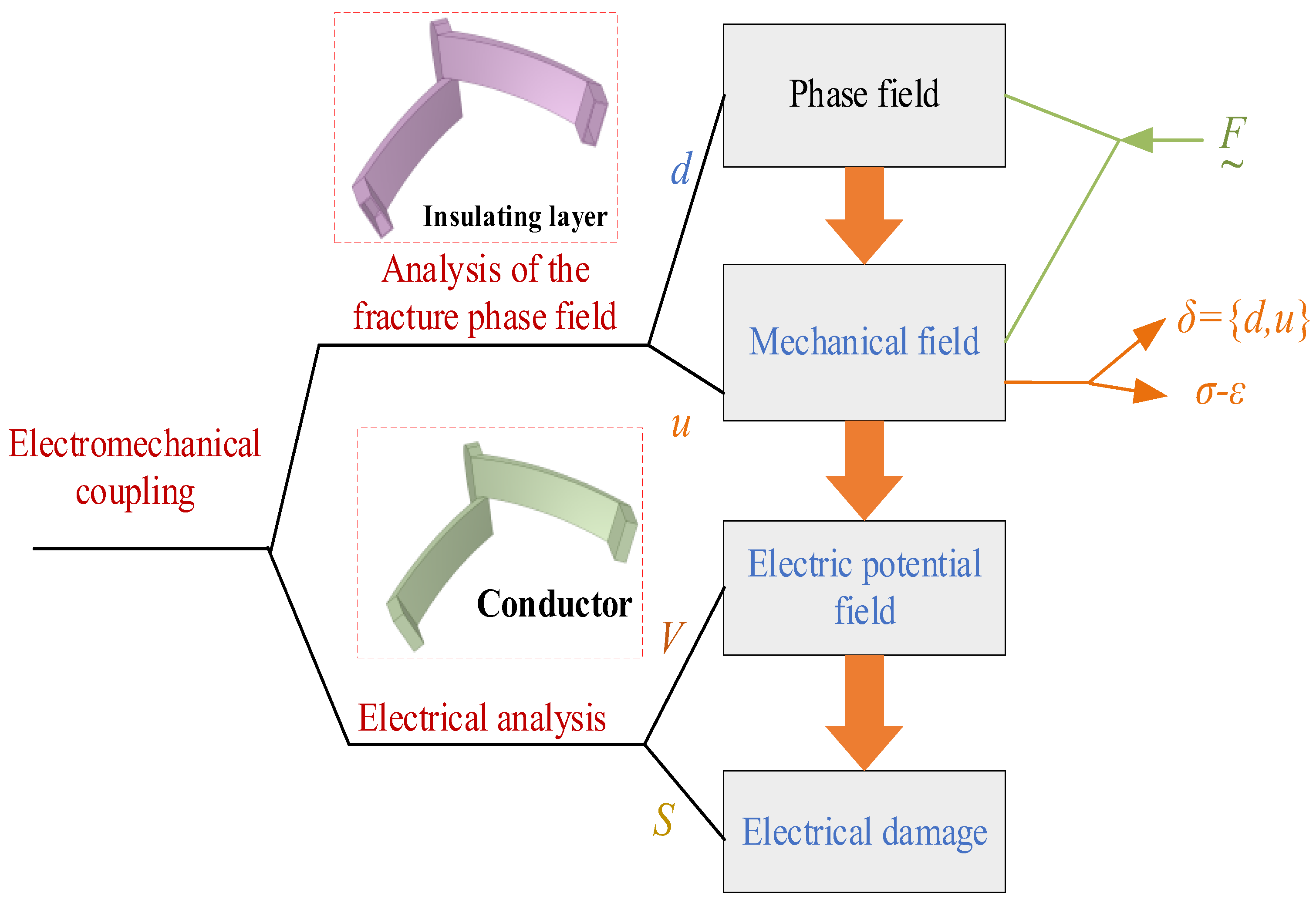
. This process iterates until convergence before proceeding to the next load step. The algorithm procedure illustrated in
Figure 4 embodies this “fix-solve-update” iterative logic. Although this decoupled strategy is an approximation, it significantly reduces computational complexity and has been widely proven sufficiently accurate and robust for most quasi-static fracture problems.
Figure 4 gives the algorithm procedure of electromechanical evolution in this paper. It mainly includes four variables, such as the phase field variable, displacement variable, electric potential variable, and electrical damage variable. The phase field and displacement field are directly coupled, and the electric potential field is the result of the joint calculation of the displacement field and phase field. Finally, the electrical damage is determined based on the current calculated potential and the defined electrical damage. It is noted that in this proposed evolution algorithm, the order of the fixed fields can be arbitrarily selected, which will not affect the calculation.
2.5. Model Parameters
The reliability of the simulation results of the electromechanical coupling phase field model established in this study is closely related to the input parameters.
Table 1 lists the key material property parameters of the epoxy resin-mica composite insulation adopted [
23]. In addition, the selection basis for the two core parameters specific to the phase field model: the characteristic length scale
l0 and the critical energy release rate
GC is explained as follows.
The two key parameters of the phase field model are selected based on the following: The characteristic length scale l0 is set to 0.05 mm. This value is determined through grid convergence analysis, aiming to ensure computational efficiency while accurately distinguishing the damage field at the crack tip. The critical energy release rate GC is taken as 300 J/m2. This value is based on the calibration results of the standard fracture mechanics experiments conducted on the VPI epoxy resin insulation system involved in this study, ensuring that the crack propagation driving force is consistent with the fracture toughness of the real material.
3. Example and Results Analysis
3.1. Equivalent Model of Ground Insulation
This paper takes a permanent magnet synchronous motor (PMSM) as an example and conducts crack propagation analysis by the equivalent insulation of the stator end winding to a two-dimensional cantilever beam model. The two-dimensional model is shown in
Figure 5. This simplified method, while maintaining the research pertinence and computational feasibility, also has certain idealized assumptions.
In actual operation, one end of the winding insulation is rigidly constrained by the stator core, while the other end bears the alternating electromagnetic force from the current-carrying conductor. The cantilever beam model is consistent with the mechanical state of the real structure in both the fixed end constraint and the free end dynamic load, and can effectively reflect the key characteristics of stress concentration and crack initiation at the insulation root. The core of this paper lies in revealing the propagation mechanism of cracks in the electromechanical coupling field, rather than precisely simulating the geometric details of specific insulation structures. The simplified model also retains key physical processes such as damage evolution and potential redistribution, and is suitable for parameter research and mechanism revelation of the phase field method. By introducing the material partitioning of mica tape and epoxy resin into this model, the influence of the composite material interface on the crack propagation path can also be effectively simulated, which is consistent with the layered structure characteristics of the actual insulation system.
However, the actual insulation is a three-dimensional curved surface structure. The two-dimensional plane assumption cannot reflect the stress state along the axial direction of the winding and the possible three-dimensional crack propagation mode, which may underestimate the stress complexity of the actual structure. This model uses uniform sinusoidal displacement loads to simulate electromagnetic force, but the actual spatial distribution of electromagnetic force is non-uniform and is affected by the coupling of thermal stress and structural vibration. The ideal rigid constraint at the fixed end also does not take into account the actual flexibility and damping characteristics of the supporting structure. In the model, it is assumed that the insulating layer is perfectly bonded to the conductor and the core, without considering the actual damage modes such as interface debonding and delamination. It may also ignore the important path of crack propagation along the interface.
The left end of the model is fully constrained to simulate the constraints provided by the stator, while the right end applies a sinusoidal displacement load to the insulation layer to characterize the influence of electromagnetic force. Set the size of the insulation domain to 2 5 × 4. Grid division is carried out using free quadrilateral elements. A total of 4000 elements and 4141 nodes were generated, and local refinement was carried out near the cracks to improve the calculation accuracy. This model also takes into account the influence of mica tape. The specific parameters of the materials used are detailed in
Section 2.5 and
Table 1, making it consistent with the actual insulation structure. The crack propagation results are shown in
Figure 5. The entire modeling, meshing and solution process is accomplished by a program written in MATLAB-R2023b.
3.2. Crack Propagation of Insulation Damage
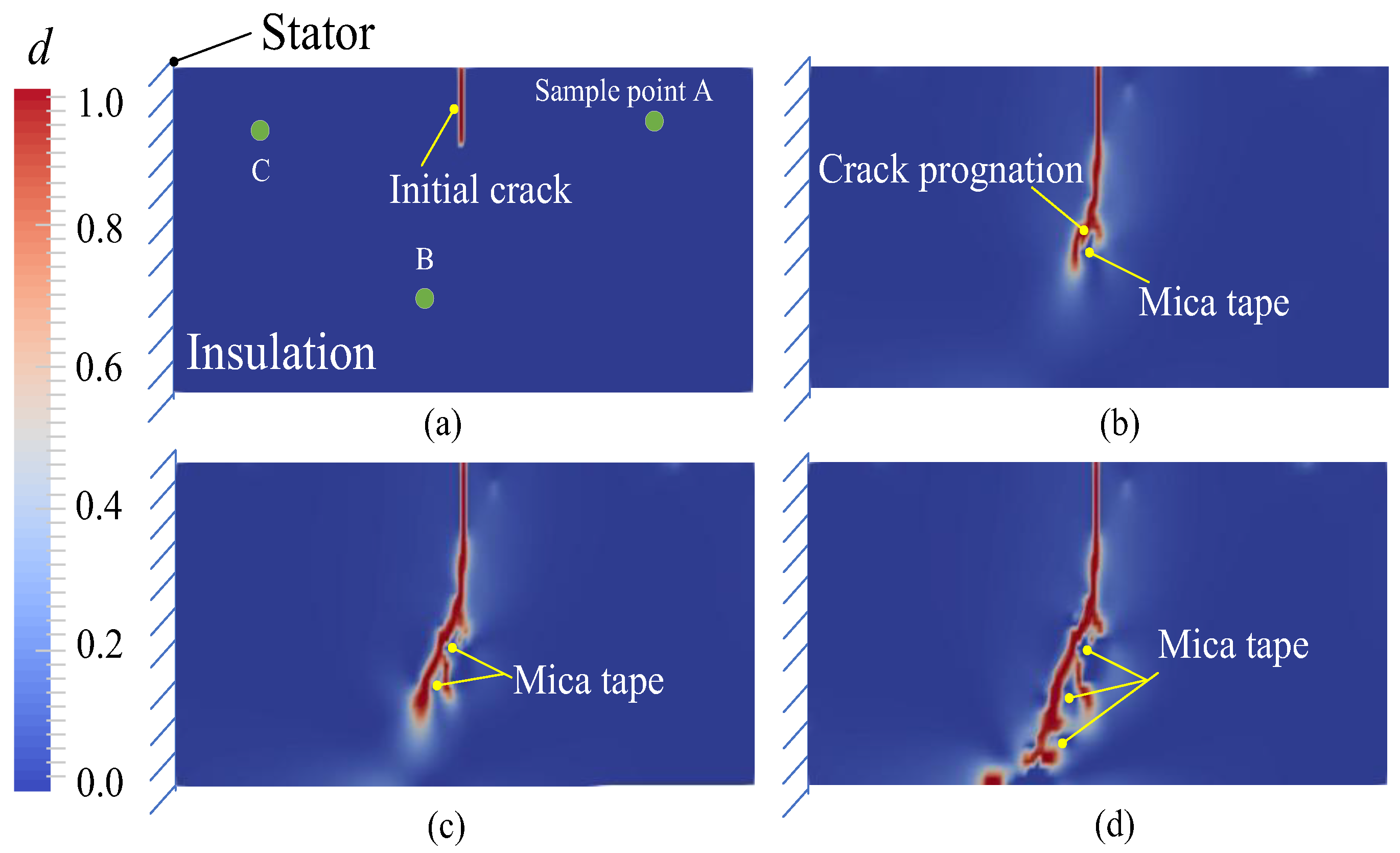
Figure 6 illustrates the gradual evolution of the insulation crack propagation along the corresponding phase field damage distribution in the continuous iteration step. Under the action of cyclic dynamic load, the cracks in the insulation layer gradually expand along the direction of principal stress, and the damage zone continues to expand. The phase field damage variable near the crack tip shows obvious spatial and temporal evolution characteristics, indicating that the model can accurately capture the dispersion fracture behavior characteristics of dynamic crack propagation.
Importantly, when the crack front is close to the mica band region, its propagation path bifurcates, which indicates that the inhomogeneity of the internal material has a strong influence on the crack evolution. The mica sheet has high stiffness and fracture toughness, which acts as a barrier to hinder the direct penetration of cracks. Therefore, the crack preferentially propagates through the epoxy resin matrix and forms a complex fracture mode near the mica interface. This behavior emphasizes the key role of the composite microstructure in guiding the crack trajectory in the insulating layer.
Overall, these findings indicate that the phase-field fracture method provides a robust prediction framework for capturing the coupling effects of material inhomogeneity and dynamic loads on crack propagation in composite insulation systems. These insights are crucial for understanding the damage mechanism of the end winding insulation of electric vehicle drive motors under operating electromagnetic stress, and can provide a reference for designing more reliable insulation structures.
To further investigate the influence of crack-induced damage on the internal stress–strain state of the insulation, three representative sample points (A, B, and C), as indicated in
Figure 6, were selected for transient mechanical field analysis.
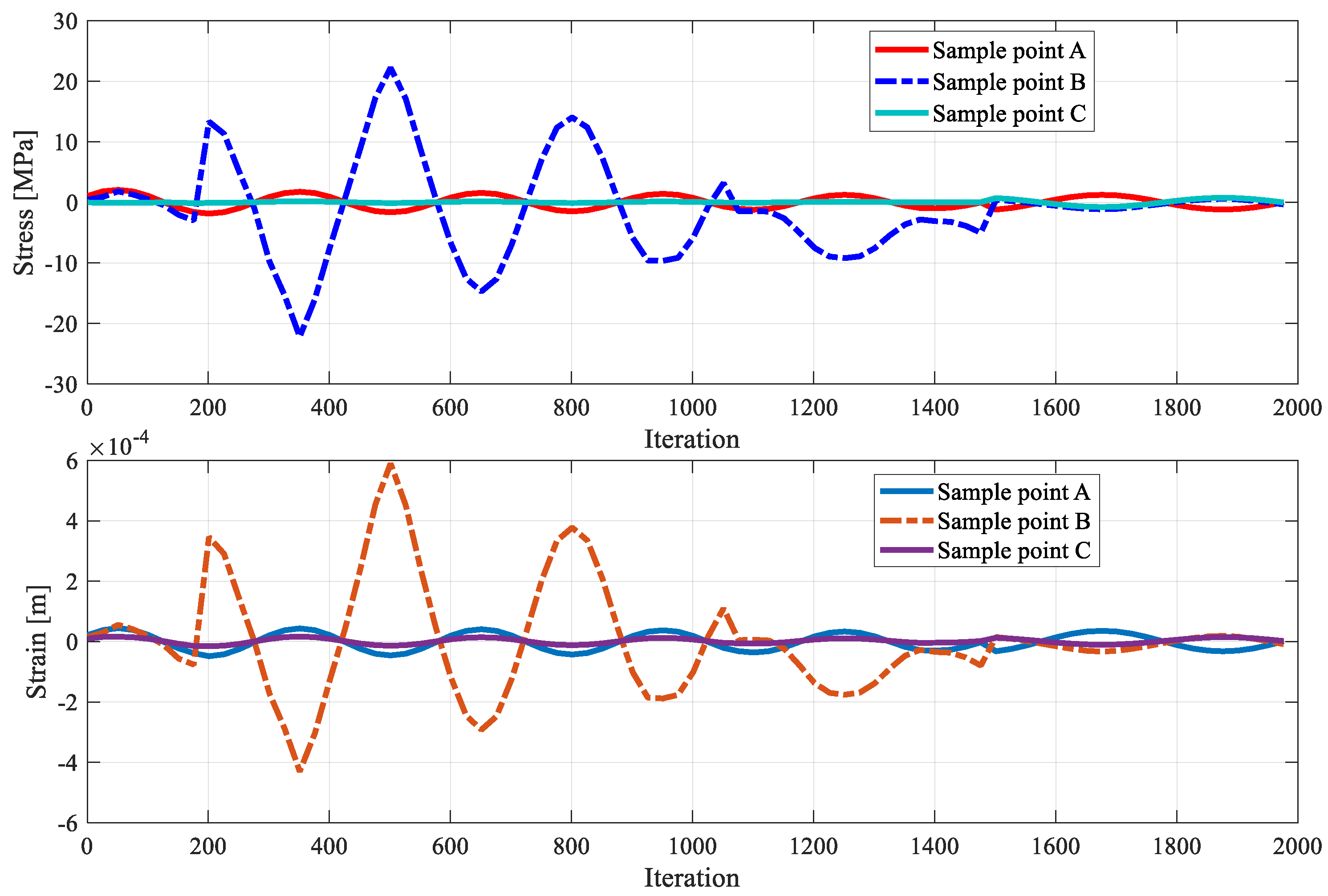
Figure 7 presents the dynamic evolution of stress and strain at these points, capturing the localized mechanical response associated with crack propagation.
The results indicate that points near the crack tip exhibit pronounced stress concentration and strain localization, reflecting the strong redistribution of mechanical fields induced by progressive damage. Point A, adjacent to the crack initiation zone, shows a rapid increase in stress and strain as the crack propagates. Point B, located near the crack tip, exhibits significantly higher stress and strain amplitudes compared with the other points. Notably, when the crack damage evolves to approximately 1400 iteration steps, point B becomes fully encompassed within the fracture zone, resulting in stress release and a rapid drop in local stress magnitude. Point C, situated farther from the crack path, shows relatively minor fluctuations, indicating that the influence of crack propagation diminishes with distance from the fracture zone.
These observations demonstrate that crack growth not only drives localized damage but also significantly alters the surrounding mechanical environment. The analysis provides detailed insight into the coupling between crack propagation and internal stress–strain redistribution in composite insulation systems, which is critical for assessing the structural integrity and operational reliability of electric vehicle drive motor end-winding insulation under electromagnetic loading.
3.3. Electrical Damage Analysis
Building upon the mechanical damage evolution of the insulation, the internal electric field distribution was analyzed under different crack propagation scenarios to evaluate the corresponding electrical degradation state.
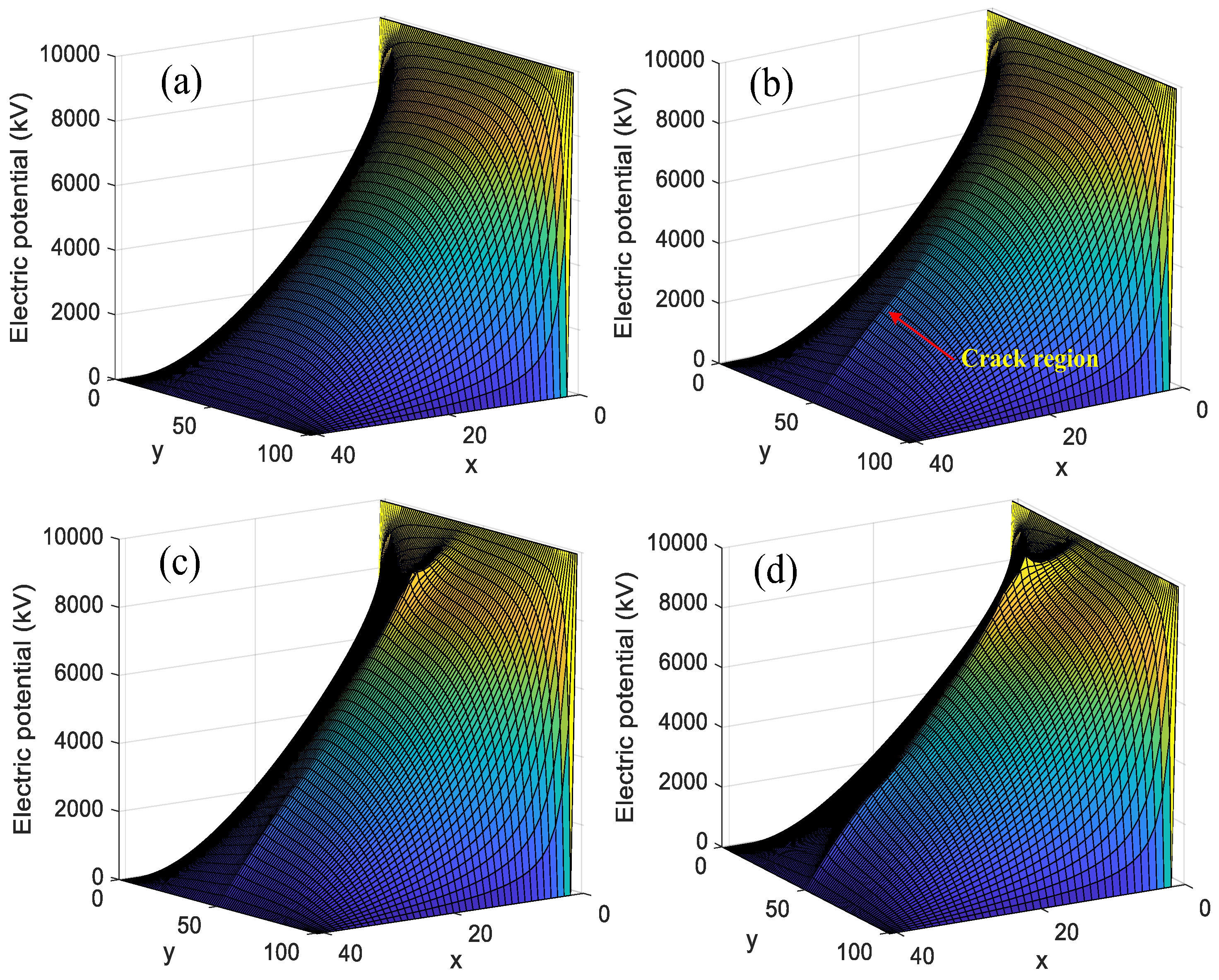
Figure 8 presents the spatial distribution of insulation potential at various iteration steps. The results demonstrate that as crack propagation progresses, the impact of mechanical damage on the potential distribution becomes increasingly significant, indicating a strong coupling between mechanical fracture and the local electric field.
Specifically, regions along the crack propagation path consistently exhibit higher electric potential compared with other areas of the insulation. This localized increase in potential can be attributed to the discontinuity introduced by the crack, which alters the electric field lines and enhances the local field intensity. The analysis reveals that crack growth not only modifies the mechanical environment but also substantially affects the internal electrostatic conditions, emphasizing the necessity of considering both mechanical and electrical interactions when assessing the degradation and reliability of composite insulation systems.
Figure 9 presents the evolution of the electrical damage variable in the insulation layer with crack propagation. The results show that as mechanical damage advances, electrical damage progressively increases, highlighting the coupled evolution of mechanical and electrical degradation. Mechanical crack growth alters local stress–strain fields and modifies the internal electric field, accelerating the accumulation of electrical damage in adjacent regions. This correlation emphasizes the importance of considering mechano-electrical interactions when assessing insulation reliability and provides insight into the synergistic degradation mechanisms of composite insulation materials.
The colored lines in the figure illustrate the progressive evolution process of the crack propagation path in the grounding insulation model under cyclic mechanical loading. Each color represents the position of the crack front in the numerical simulation at a specific iteration step, intuitively reflecting the development process of the damage over time: the sequence of colors from cool tones to warm tones (blue → green → yellow → orange → red) directly maps the expansion process of the crack over time, with warm tones representing later simulation times and greater cumulative damage. d(x), where values closer to 1 (red hues) correspond to fully fractured material and values near 0 (blue hues) indicate intact insulation.
4. Discussion
The electromechanical coupling phase field model established in this paper closely links the microstructure, damage evolution and macroscopic performance failure of insulating materials. Research shows that cracks propagate in the epoxy resin matrix and deflect or fork at the mica tape interface (
Figure 6), indicating that the material interface is a key controlling factor for crack propagation. This phenomenon is highly consistent with the results observed by Tanaka et al. [
14] after conducting mechanical fatigue experiments on epoxy-mica insulation systems. Their cross-sectional analysis indicated that the failure mainly occurred along the resin-mica interface or the resin matrix, rather than penetrating the mica sheet. Similarly, Zhang et al. [
9] also reported a similar pattern of crack propagation along the weak interface of the material in the fracture analysis of the insulation of the end winding of the traction motor. Moreover, the propagation of mechanical cracks leads to significant distortion of the local electric field and an increase in potential (
Figure 8), and the electrical damage variable also grows accordingly (
Figure 9), revealing the coupled evolution of electromechanical damage. A large number of experimental studies indirectly support this coupling relationship. For instance, Liu et al. [
15] observed in the composite insulation of wind turbine generators that the starting point of partial discharge (PD) activity was closely related to the location of material defects (which can be regarded as pre-damage). The aging study by Nair and Vishwanath [
16] also indicates that the dielectric performance degradation of insulation (such as an increase in loss factor) occurs simultaneously with the accumulation of internal microscopic damage. In addition, the phase field modeling framework adopted in this paper avoids the complexity of simulating fractures in traditional methods and has good universality and engineering application potential. By adjusting the model parameters and load conditions, it can directly serve the predictive design and weak link assessment of the insulation structure of electric vehicle drive motors (such as PMSM).
Based on the achievements and limitations of this study, future work can be further explored from the following aspects:
Introduce the thermal field for the full coupling analysis of heat, force and electricity. When the motor is running, the heating of the windings can cause the insulation material to soften, stress relaxation, and generate thermal stress, which has a crucial impact on the initiation and propagation of cracks.
Establish a three-dimensional fine model, taking into account the real spatial configuration of the end winding and the interaction of multiple cracks. At the same time, specialized experiments need to be designed (such as applying electromechanical composite stress to insulating specimens with pre-formed cracks) to quantitatively verify the crack propagation path, speed and final breakdown voltage predicted by the model.
By correlational the damage evolution laws revealed in this study with macroscopic performance degradation (such as a decrease in insulation resistance and an increase in partial discharge), a physics-based, electromechanical coupled insulation life prediction model is developed to provide a more scientific decision-making basis for the condition-based maintenance and health management of motors.
5. Conclusions
This paper investigates the electromechanical damage coupling in the ground insulation of electric vehicle drive motor stator end-windings. The propagation of initial cracks under dynamic mechanical loads and their influence on the internal electric potential distribution are analyzed. Transient simulations using a coupled phase-field and electromechanical model capture the progressive damage evolution in composite insulation materials, including epoxy resin and mica tape. The principal conclusions can be summarized as follows:
- (1)
Simulation shows that the crack propagates along the principal stress direction under dynamic loading and forks when encountering material interfaces such as mica tape. This explains mechanically the phenomenon observed in engineering that insulation failure often develops along the weak interfaces of materials, providing a direct basis for optimizing the material layout and process of insulation structures.
- (2)
The study captured the stress concentration in the crack tip area and the subsequent release process and simultaneously obtained a significant distortion of the local potential. This is the first time that the synchronous quantitative description of mechanical damage and electrical performance degradation (characterized by potential changes) has been achieved within a unified framework, laying the foundation for establishing insulation state assessment indicators based on physical field quantities.
- (3)
The proposed phase field model avoids the problem of mesh redivision in the traditional finite element method for simulating crack propagation, providing an efficient and practical numerical analysis tool for the reliability design of motor insulation systems. This framework can be directly used to evaluate the damage evolution trend under different winding forms (such as hairpin type or traditional winding type) and different insulation material formulations, serving the forward design and life prediction of products.
The value of the electromechanical coupling phase field model proposed in this study lies not only in revealing the mechanism but also in providing a transformative tool for industrial practice. At the condition monitoring level, the crack–electric field coupling law revealed by the model has laid a theoretical foundation for the development of early warning technologies based on new methods such as dielectric spectrum analysis and is expected to overcome the lag of traditional partial discharge monitoring. At the level of life prediction and reliability management, this model transforms insulation life assessment into a computable crack propagation dynamics problem, supporting the establishment of physics-based prediction models. This drives the design of motor insulation systems to shift from relying on empirical safety factors to predictive design based on simulation and provides core model support for achieving individualized digital twin health management.
Author Contributions
Conceptualization, Z.L.; data curation, Z.L.; funding acquisition, X.M.; investigation, Z.L.; methodology, Z.L., X.M. and X.W.; software, Z.L.; supervision, X.M. and H.W.; visualization, Z.L.; writing—original draft, Z.L.; writing—review and editing, X.M., X.W., H.W. and D.Z. All authors have read and agreed to the published version of the manuscript.
Funding
This work was supported by the National Natural Science Foundation of China (Grant Nos. 52472405), the Hubei Province Central Guiding Local Science and Technology Development Special Project (2024CSA081), the Natural Science Foundation of Hubei Province (Grant Nos. 2024AFB219, 2024AFD042, 2024AFD045), the Open Fund of Hubei Longzhong Laboratory (2024KF-22),and the Special Fund of Hubei Longzhong Laboratory of Xiangyang Science and Technology Plan (2024KF-22).
Data Availability Statement
The original contributions presented in this study are included in the article. Further inquiries can be directed to the corresponding author.
Conflicts of Interest
The authors declare no conflicts of interest.
References
- Lee, H.; Kim, H.; Jeong, J.; Lee, K.; Lee, S.B.; Stone, G. Inverter-embedded partial discharge testing for reliability enhancement of stator winding insulation in low voltage machines. IEEE Trans. Ind. Appl. 2022, 58, 2088–2096. [Google Scholar] [CrossRef]
- Li, L.; Fu, W.; Niu, S. Novel steel-bar starting cage line-start permanent magnet machine with spoke-type insulation layers. IEEE Trans. Magn. 2022, 58, 1–5. [Google Scholar]
- Yang, C.; Liu, W.; Niu, S.; Lyu, J.; Chau, K.T. Parameter-Tuning-Free Two-Step Identification of Mechanical Parameters for PMSM Drives. IEEE Trans. Ind. Electron. 2025, 72, 12378–12392. [Google Scholar] [CrossRef]
- Yang, C.; Liu, W.; Song, B.; Xie, X.; Niu, S.; Chau, K.T. Signal-Injection-Based Efficient Direct-Determination of Controller Gains and Nonlinear Friction Compensation Values in SPMSM Drives. IEEE Trans. Power Electron. 2025, 41, 1627–1633. [Google Scholar] [CrossRef]
- Guo, Y.; Xu, W.; Ge, J.; Xiao, H.; Tang, Y.; Shangguan, Y. A DSVM-Based MPC Strategy with Magnetizing Inductance Online Identification Method for Thrust Ripple Suppression in Linear Induction Machine. IEEE Trans. Power Electron. 2025, 40, 10746–10757. [Google Scholar] [CrossRef]
- Zhao, Z.; Jie, H.; Tao, M.; Li, H.; Sun, Q.; Gao, R.X.-K. High-Frequency Impedance Modeling of Induction Motors Using Adaptive Multistage RLC Circuit and Neural Network-Based Stagewise Parameter Identification. IEEE Trans. Ind. Electron. 2024, 72, 3357–3369. [Google Scholar] [CrossRef]
- Keller, M.; Petri, T.; Waldhof, M.; Schuller, F.; Maier, M.; Parspour, N. Modeling the dynamic voltage distribution in electric traction motor windings and its application on HV optimal winding design. IEEE Trans. Ind. Appl. 2024, 60, 3820–3829. [Google Scholar] [CrossRef]
- Zhang, H.; Zhang, B.; Cao, G.; Wang, S. Fatigue propagation characteristics of insulation crack failure in stator end-winding for large traction motor based on magnetic-thermal-mechanical coupling model. IEEE Trans. Dielectr. Electr. Insul. 2024, 31, 2111–2119. [Google Scholar] [CrossRef]
- Zhang, H.; Zhang, M.; Wang, X. Fracture failure analysis of insulation with initial crack defect for stator end-winding in in duction motor by using magnetic-structural coupling model. Eng. Fail. Anal. 2023, 149, 107239. [Google Scholar]
- Zhang, Z.; Wu, T.; Gu, M. Study on the performance of CFETR PF coil insulation system under the fatigue load at low temperature. J. Anhui Polytech. Univ. 2022, 37, 41–48. [Google Scholar]
- Lin, M.; Li, Z.; Li, Z. Application of molecular dynamics simulation in the study of damage and repair mechanism of cable insulation sheath materials. Guangdong Electr. Power 2024, 37, 102–110. [Google Scholar]
- Guo, Y.; Dong, Z.; Li, Q. Research advances in phase field simulation of dielectric properties of composite insulating materials. Adv. Technol. Electr. Eng. 2021, 40, 53–63. [Google Scholar]
- Tariq, M.A.; Kashif, S.A.R.; Rasool, A.; Ali, A. Torque Smoothness for a Modified W-Type Inverter-Fed Three-Phase Induction Motor with Finite Set Model Predictive Control for Electric Vehicles. World Electr. Veh. J. 2025, 16, 539. [Google Scholar]
- Tanaka, K.; Kojima, H.; Onoda, M.; Suzuki, K. Prediction of residual breakdown electrical field strength of epoxy-mica paper insulation systems for the stator winding of large generators. IEEE Trans. Dielectr. Electr. Insul. 2015, 22, 1118–1123. [Google Scholar] [CrossRef]
- Liu, X.; Wang, J.; Zhang, R.; Xue, C.; Chen, H.; Li, Y. Electrical tree characteristics under AC and repetitive pulse voltages in wind turbine generator composite insulation. IEEE Trans. Dielectr. Electr. Insul. 2020, 27, 1007–1014. [Google Scholar] [CrossRef]
- Nair, R.P.; Vishwanath, S.B. The applicability of very low frequency diagnostic testing in the evaluation of thermally aged stator coil. IEEE Trans. Dielectr. Electr. Insul. 2023, 30, 1223–1230. [Google Scholar] [CrossRef]
- Hayashi, M.; Kawakami, T.; Adachi, S.; Wang, J.; Sakai, K. Crack detection for welded joint with surface coating using unsaturated ac magnetic flux leakage. IEEE Trans. Magn. 2022, 58, 6201205. [Google Scholar] [CrossRef]
- Wang, W.; Huang, S.; Zhang, J.; Long, Y.; Wang, S.; Zhao, W. An approximate analytical model of surface cracks in ac field measurement technique. IEEE Trans. Magn. 2022, 58, 6200909. [Google Scholar] [CrossRef]
- Wang, L.; Yin, Z.-Y.; Chen, W. Characteristics of crack growth in brittle solids with the effects of material heterogeneity and multi-crack interaction. Int. J. Fract. 2024, 246, 77–99. [Google Scholar] [CrossRef]
- Zhu, M.X.; Li, J.C.; Song, H.G.; Chen, J.M. A phase field model for the propagation of electrical tree in nanocomposites. IEEE Trans. Dielectr. Electr. Insul. 2020, 27, 336–342. [Google Scholar] [CrossRef]
- Kang, Q.; Peng, D.; Xi, W.; Qu, Y. Fracture phase-field method-based circumferential surface crack propagation investigation of pipeline. Chin. J. Ship Res. 2024, 19, 302–309. [Google Scholar]
- Lo, Y.-S.; Borden, M.J.; Ravi-Chandar, K.; Landis, C.M. A phase field model for fatigue crack growth. J. Mech. Phys. Solids 2019, 132, 103684. [Google Scholar] [CrossRef]
- Kiran, R.; Nguyen-Thanh, N.; Yu, H.; Zhou, K. Adaptive isgeometric analysis-based phase-field modeling of interfacial fracture in piezoelectric composites. Eng. Fract. Mech. 2023, 288, 109181. [Google Scholar] [CrossRef]
| Disclaimer/Publisher’s Note: The statements, opinions and data contained in all publications are solely those of the individual author(s) and contributor(s) and not of MDPI and/or the editor(s). MDPI and/or the editor(s) disclaim responsibility for any injury to people or property resulting from any ideas, methods, instructions or products referred to in the content. |
© 2026 by the authors. Published by MDPI on behalf of the World Electric Vehicle Association. Licensee MDPI, Basel, Switzerland. This article is an open access article distributed under the terms and conditions of the Creative Commons Attribution (CC BY) license.