Abstract
Established hairpin stators for electric traction motors are made up of a large number of so-called hairpins. To produce these stators, the individual hairpins must first be pre-assembled into an auxiliary device in order to achieve the desired winding scheme. The resulting hairpin basket must then be picked up and transported to the lamination stack. Automated solutions for both processes are characterized by a high degree of complexity and low flexibility. Manual assembly, however, is prone to errors. The new approach presented in this paper is therefore based on the collaborative assembly of the hairpins and a flexible hairpin basket gripper. A cobot hands the hairpins in the correct sequence to the operator. The correct positioning of the hairpins in the auxiliary device is ensured by the use of a monitor located under it. The creation of the correct assembly sequence is partly automated by a collision detection program. In addition, a new and flexible hairpin basket gripping concept is presented. Tests show that the cycle times of both new processes are slow due to hardware limitations. This restricts their use to specific applications, such as complex winding patterns or very small quantities.
1. Introduction
Hairpin technology has become the predominant technology for stators in electric traction motors in recent years due to its advantages in terms of product and production. By using flat wires, higher slot fill factors can be achieved compared to round wire windings, which is reflected in a higher motor efficiency [1]. Furthermore, the production of hairpin stators is characterized by a high degree of automatability [2].
The winding of a hairpin stator consists of a large number of so-called hairpin coils (referred to simply as hairpins in the following), which are first bent into their typical U-shape from a wire coil and then assembled manually or automatically into the desired winding pattern. The assembled winding made up of all the hairpins is called the hairpin basket. This assembly process (also called pre-assembly) is particularly error-prone when performed manually, as it may lead to hairpins being damaged or incorrectly positioned. Due to high tolerance requirements and the complex structure of the hairpin basket, which consists of hundreds of hairpins, the assembly process can only be automated using highly specialized machinery. For this reason, a collaborative hairpin assembly process is presented below, which uses flexible, manual assembly, but makes it safer through the use of a cobot and visual support for the worker. The process was first presented and introduced in [3].
After the hairpin basket has been assembled, it must be gripped, lifted out of the auxiliary device, and threaded into the lamination stack. To do this, the hairpins in the gripper must be aligned very precisely. State-of-the-art grippers are complex and inflexible, which is why a new approach for gripping and aligning hairpin baskets in a more flexible way is being introduced.
2. Basics and State of the Art
2.1. Hairpin Technology
An example of a hairpin stator can be seen in Figure 1a. The winding can be divided into the part located in the lamination stack and the two winding heads. These can in turn be divided into the bending side and the twisting side, whose names derive from the production process explained later. Section view A-A (Figure 1b) can be used to explain the properties of the stator that are relevant for the subsequent pre-assembly process. In this example, there are 36 slots (slot number ) and 4 layers (number of layers ), which means that there are 4 hairpin legs in each slot. Two layers each form a so-called hairpin ring. With the exception of special hairpins, each regular hairpin has two legs in two different layers of one hairpin ring. The number of slots and layers results in a total hairpin number with for a typical hairpin stator. Typical values for the number of slots are 36 or 48, but significantly larger numbers such as 72 or 96 are also possible, depending on the electromagnetic design. The number of layers is typically between 4 and 10, which can result in a hairpin number of several hundred for stators. The connection of the stator is either on the bending or twisting side. Either the bending or twisting process is accordingly complex. In the stator shown, the connections are located on the bending side in the form of I-Pins, which are explained in more detail in Section 2.3.
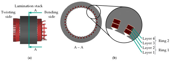
Figure 1.
(a) Typical hairpin stator design; (b) Section view showing the different layers and rings.
2.2. Process Chain of Hairpin Technology
The process chain for manufacturing hairpin stators has already been described extensively in previous works, such as [4,5]. The basic process steps shown in Figure 2 can be derived from this. Starting from a coil, the wire is unwound, straightened, stripped at defined points and finally bent into the desired three-dimensional shape. Due to mutual overlaps, it is usually not possible to insert the individual hairpins directly into the lamination stack, which is why they are first pre-assembled into an auxiliary device outside the lamination stack. The entirety of these hairpins is referred to as a hairpin basket. The hairpin basket is then gripped, transported over the lamination stack and inserted axially into it. To achieve the desired winding scheme, the hairpin legs protruding from the lamination stack are twisted and two of the previously stripped ends are contacted using a laser welding process. To improve the stator’s heat dissipation and robustness against external influences, it is often impregnated as a final step.
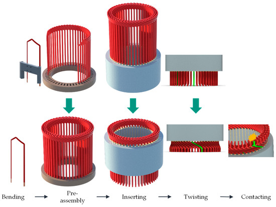
Figure 2.
Process chain for manufacturing of hairpin stators.
2.3. Classification of Hairpin Shapes, Types and Topologies
In order to better understand the pre-assembly process, existing hairpin shapes, hairpin types and topologies should first be analyzed. Due to the large number of different stator and winding designs, no claim is made to completeness of the hairpin types and topologies. For example, there are certainly stators whose winding scheme cannot be completely described with the help of the classification presented. Nevertheless, it helps to understand the influence of the winding scheme on the pre-assembly process.
The typical shape of a hairpin is shown in Figure 3. Important geometric properties to describe the shape of a hairpin are its leg length and pitch span. Furthermore, the radius of both legs and the angle between them can be used to describe the shape, which is particularly important for the gripper design in the pre-assembly process. The three-dimensional, complex shape of the hairpin crown will not be discussed in detail here, as hairpins are usually gripped by the legs.
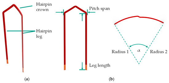
Figure 3.
(a) Typical hairpin shape; (b) Basic geometric parameters to describe a hairpin.
In addition to the geometric description of their shape, hairpins can also be divided into hairpin types according to their function in the winding scheme. There are different hairpin types within a stator, which result from the electromagnetic stator design respectively the winding scheme. Each hairpin type results in a different shape. The design of hairpin windings and rules for their design have already been published in detail, for example in [6,7,8,9,10]. Without claiming to be exhaustive, the most important types of hairpins are as follows.
First, there are the already mentioned regular hairpins, whose legs are in two different layers of one hairpin ring. These regular hairpins make up the majority of hairpins in a stator. As will be explained later, the number of regular hairpins with different shapes per hairpin ring is not limited to one. In certain winding schemes, two or more regular hairpins with different pitch spans can also occur within one hairpin ring. Due to the different diameters of each hairpin ring, regular hairpins of different hairpin rings also have different radii of their legs, see Figure 3b. The number of different regular hairpin shapes is therefore at least equal to the number of hairpin rings, but can also be greater. Since the regular hairpins are only arranged in one ring, additional hairpin types are required to connect the rings to each other. Accordingly, the legs of these so-called jumpers are located in different rings. For example, the legs are located in layers 2 and 3 to connect rings 1 and 2. Another type of hairpin is the so-called I-pin. These only have one leg and are used for subsequent interconnection. In addition, hairpins can be installed with both legs in the same layer (single-layer hairpins) or in layers that are not adjacent to each other. The number of special hairpins is usually significantly smaller than the number of regular hairpins. It is not always possible to distinguish hairpin shapes with the naked eye due to the slight geometric deviations between two shapes, which increases the susceptibility to errors in the pre-assembly process.
In addition to the shape respectively the geometric properties of an individual hairpin and its assignment to one of the hairpin types mentioned above, its location in relation to its neighbors is important for the pre-assembly process. This arrangement of two or more hairpins is referred to as topology in the following. To illustrate the topology of hairpins more clearly, the stator is mentally unwound as shown in Figure 4. The examples show a stator section with four layers and eight slots. The positions of the first and second legs of the hairpins in the stator are color-coded. Figure 4a,b show the most common topology, which is why it is referred to below as the standard topology. Here, both hairpins have the same span. Accordingly, both legs of the second hairpin are offset by one slot from those of the first hairpin. In the case of the standard topology combined with regular hairpins, the legs are in adjacent layers; in the case of single-layer hairpins, they are in the same layer. It is clear from this illustration that the standard topology with regular hairpins can be used to form an entire hairpin ring with—in the case of a stator with 36 slots—36 hairpins. This is not possible with single-layer hairpins because the second legs occupy the slots of the same layer. In the example shown, no further hairpin could be inserted in slot 7, as this slot is already occupied by the second leg of the hairpin with its first leg inserted in slot 1. For this reason, the standard topology with single-layer hairpins is only used for a certain number of hairpins, referred to below as a hairpin group. Such a hairpin group often consists of two or three hairpins, for example. Another common topology is the tangentially-stacked topology shown in Figure 4c,d. Again, it can consist of regular hairpins (c) or single-layer hairpins (d). In this case, both legs of one or more hairpins lie tangentially between the legs of an outer hairpin. The tangentially-stacked topology with regular hairpins is an example for two regular hairpins with different shapes within one hairpin ring. Finally, the radially-stacked topology is introduced in Figure 4e, which describes the position of two radially adjacent hairpins. Here, both legs of one or more hairpins lie radially between the legs of an outer hairpin. According to the hairpin types introduced above, this topology is only possible with special hairpins whose legs are in non-adjacent layers.
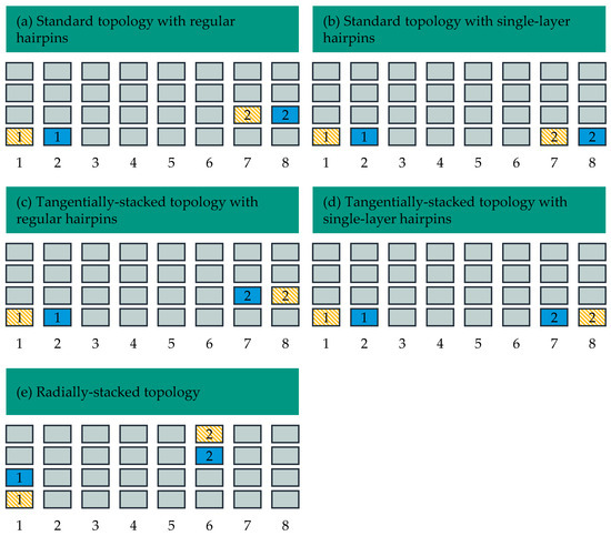
Figure 4.
Different topologies of hairpins. The positions of both legs of two hairpins relative to each other are shown in each subfigure. The two legs of a hairpin are the same color and are numbered 1 and 2.
Different topologies can be combined within a hairpin group. Two examples are given in Figure 5, each consisting of three hairpins. Within the group, the standard topology is combined with the tangentially-stacked topology with single-layer hairpins.
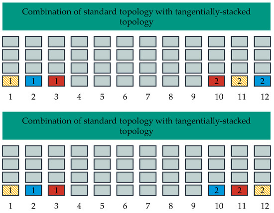
Figure 5.
Two examples for the combination of different topologies in a hairpin group of three hairpins. The positions of both legs of three hairpins relative to each other are shown in each subfigure. The two legs of a hairpin are the same color and are numbered 1 and 2.
2.4. Pre-Assembly of Hairpin Baskets
The hairpin types and topologies described in Section 2.3 generally result in mutually overlapping hairpins. For example, the standard topology with regular hairpins results in the overlapping shown in Figure 6a. It can be seen that the legs of the first hairpin lie above and below one leg of the second hairpin. This results in the problem that the hairpins cannot be pre-assembled purely axially in z-direction. Possible movements that allow the collision-free pre-assembly of two regular hairpins in theory are shown in Figure 6b, although no auxiliary devices that could further restrict the possible movements are yet included in these considerations. In practice, it is almost impossible to insert all hairpins directly into the lamination stack automatically, as the joining gap in the slot is too small to perform the required movement of the hairpin. Even though direct insertion by manual assembly may be possible by carefully bending already assembled hairpins to the side in order to assemble further hairpins, it is common practice to first pre-assemble the hairpins in an auxiliary device, both manually and automatically. Even in this case, however, it is essential to adhere to a winding design-specific assembly sequence that allows collision-free assembly.
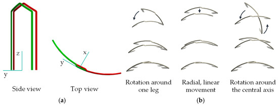
Figure 6.
(a) Overlapping of two hairpins; (b) Possible movements for collision-free pre-assembly.
During manual assembly, the hairpins in the auxiliary device generally have more play than in the stator slots, which means that hairpins that have already been assembled can be pushed to the side slightly in order to set the next hairpin. Care must be taken not to apply any plastic deformation to the hairpins. Due to the large number of hairpins and different hairpin shapes, long process times and a high susceptibility to errors are to be expected during manual assembly. For this reason, lookup-tables are required that specify the assembly sequence. Nevertheless, the risk of setting wrong hairpins or placing correct hairpins in the wrong positions is high.
Automated assembly is often robot-based (for scientific approaches, see [2,11]), whereby not all hairpins are necessarily placed directly into a single assembly device to form the entire hairpin basket. Instead, the hairpin basket respectively the assembly device is often separated into individual rings or segments, which are then joined together in further steps to form the entire hairpin basket. It may also be necessary to set individual special hairpins at a later stage. Separating the hairpin basket greatly reduces the complexity of the individual process steps to be carried out by a robot. Examples of the segmentation of the hairpin basket can be found in [12,13]. The pre-assembly of single rings is often implemented by first setting the hairpins into the auxiliary device in a spread-out position and then screwing in the hairpins. A schematic representation of the separation of the hairpin basket into rings or segments can be seen in Figure 7. In order to achieve satisfying cycle times in the automated assembly of hairpins, the corresponding systems are usually optimized for a defined winding design and are correspondingly complex and inflexible.
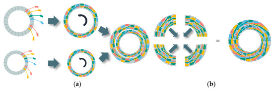
Figure 7.
Schematic representation of an automated assembly of hairpin baskets; (a) Pre-assembly of single hairpin rings; (b) Separation of the hairpin basket into several segments.
Regardless of the pre-assembly method and degree of automation, it is essential to follow the correct assembly sequence, as this is the only way to ensure simple assembly that is gentle on the hairpins. Improper handling of the hairpins may result in damage to their shape or insulation. The former primarily results in problems or errors in subsequent processes (assembly, insertion, twisting, and welding) or incorrect dimensions, e.g., of the winding head. The latter can lead to defective motors. Incorrect assembly, either due to an incorrect assembly sequence or incorrect positioning of the hairpins, also usually results in electrically incorrect and non-functional windings.
Figure 6 shows that when gripping the hairpins from the outside and using an assembly movement radially inwards (in x-direction), the red hairpin must be set first and the green hairpin second. For manual assembly, the correct assembly-sequence and hairpin position usually offer enough information for the worker to assemble the hairpin basket. In the case of automated assembly, however, the assembly sequence as well as the gripper movement must be coordinated in the form of an assembly instruction. For stators with several hundred hairpins, these assembly instructions can become complex and extensive depending on the complexity of the winding—especially the number of special hairpins—and require a great deal of experience on the part of the worker or work planner.
2.5. Hairpin Grippers
The options shown in Figure 6b for pre-assembling hairpins without collision often result in radial assembly movements from the outside inwards. This in turn results in grippers that can grip the hairpins from the outside, e.g., using electric or pneumatic parallel jaw grippers. Both legs are gripped to ensure a secure hold even at high speeds. Due to the different shapes of hairpins, different configurations of the gripper are required, which is why it can be equipped with several pneumatic or electric actuators that allow the parallel jaw grippers to be positioned flexibly in relation to each other. Such flexible grippers are on the one hand complex, expensive and time-consuming to manufacture. On the other hand, they are heavy due to the actuators installed, which makes relatively large robots necessary to handle the hairpins weighing only around 50 g.
2.6. Gripping and Insertion of the Hairpin Basket
Once all the hairpins have been assembled in the auxiliary device, the hairpin basket must be gripped and guided into the slots of the stator lamination stack. Due to the small joining gap between the slot and the hairpins, this process requires great precision. On the one hand, this can be achieved using an auxiliary device that is fed in radially over the front of the lamination stack before the joining process. This device has insertion chamfers that guide the legs of the hairpins safely into the slots. An additional function is to protect the slot insulation paper from damage or being drawn into the slot. On the other hand, the hairpins should be aligned as precisely as possible by the hairpin basket gripper itself so that the play in the auxiliary device is eliminated. A detailed description of the process can be found in [14]. A schematic representation of the hairpins in the auxiliary device with play can be seen in Figure 8a. The hairpins have no defined orientation and position. Figure 8b shows the aligned hairpins as they should be in the hairpin gripper. How this alignment is implemented technically can vary greatly.
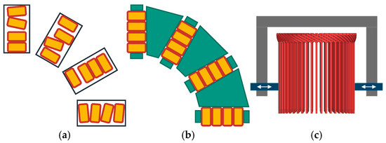
Figure 8.
Schematic representation of the alignment process of hairpin baskets; (a) Pre-assembled, non-aligned hairpins in an auxiliary device with play; (b) Aligned hairpins fixed in the hairpin basket gripper; (c) Basic structure of a hairpin basket gripper with adjustable fingers (blue color).
2.7. Hairpin Basket Grippers
Hairpin basket grippers usually have complex mechanical components to ensure both exact positioning and secure fixation of the hairpins. Radially feedable fingers, which move between the rows of hairpins, are often used to realize these functions. The number of fingers corresponds to the number of stator slots, which means that the mechanics can be extremely versatile. In addition, the gripper design is highly inflexible with regard to the stator design. As a result, extensive set-up work or new gripper designs are usually necessary if stator properties such as diameter, number of slots, number of layers or wire cross-section change. The basic structure of a hairpin basket gripper with adjustable fingers is shown in Figure 8c. The gripper is usually mounted on a gantry to lift the hairpin basket out of the auxiliary device and transport it to the lamination stack.
3. New Approaches for the Assembly and Gripping of Hairpin Baskets
In order to address the described disadvantages of manual and automated hairpin assembly as well as hairpin basket gripping, an approach for collaborative hairpin assembly and a new hairpin basket gripper design will be presented below. The collaborative hairpin assembly offers better support for the worker through the use of a cobot and visual representations, thus reducing the susceptibility to errors in the process while retaining the flexibility of manual assembly as much as possible. The new hairpin basket gripper design with a sequential alignment process provides greater flexibility in terms of stator design and significantly reduced mechanical set-up work. Both approaches have standard interfaces with upstream and downstream processes and could therefore be integrated into existing lines.
3.1. Vacuum Hairpin Gripper
In order to keep both the complexity and weight of the hairpin gripper low, an additively manufactured vacuum gripper is used for collaborative hairpin assembly (for more information see [15]). The 3D-printed base body has threaded inserts into which the suction cups can be screwed. The grippers presented here were made from PETG (polyethylene terephthalate glycol) on a standard FFF-printer (Fused Filament Fabrication). Alternatively, they can also be produced using a laser sintering process [15]. This provides even greater design freedom. For example, it enables an additively manufactured Venturi nozzle for vacuum generation to be printed directly into the gripper, or fibres to be integrated for reinforcement. For reasons of performance in terms of vacuum quality and simplicity, the laser sintering process was not used in this paper.
Vacuum grippers have a number of advantages. On the one hand, these grippers are cheap, lightweight (40 g [15]) and can be completed within a day on a regular 3D-printer. On the other hand, such a gripper poses little risk to the worker as it has no moving or clamping elements. It should be mentioned that if the compressed air fails, the vacuum breaks down and the workpiece can no longer be gripped securely by a vacuum gripper. However, this risk is considered to be low for hairpins for electric traction motors weighing around 50 g. The risk of premature failure of the vacuum gripper due to deformed hairpins or contamination is also considered to be low due to the high requirements for geometric tolerances of the hairpins, as well as cleanliness in stator production in general. One disadvantage is the properties of the suction cups. Very small suction cups are required for small wire cross-sections. However, these lose flexibility with decreasing size, so that slight deviations in position between the hairpin and the suction cups (e.g., an angular offset) can more easily lead to a vacuum leak. For this reason, it is important to ensure that the threaded inserts are inserted at right angles into the 3D-printed base body. In addition, the hairpins must be provided with great precision. In principle, aluminum base bodies could be used, which would better meet the requirements for precision. However, this would result in a higher weight compared to PETG (with an infill of 30% for the 3D-printed part approximately seven times) and increased manufacturing costs, particularly due to the complex installation of the vacuum channels. Grippers with base bodies made of aluminum were therefore not tested. The measures mentioned above ensured secure gripping using an additively manufactured vacuum gripper.
A dependence of the vacuum gripping force on the hairpin insulation, usually PEEK (polyether ether ketone), PI (polyimide) or PAI (polyamide-imide) [16], could not be determined. This is also consistent with investigations into the coefficient of friction of insulation materials, in which only slight differences were found between PEEK and PAI [17].
Due to their simple design, the vacuum grippers used here can only grip a single hairpin shape. This means that as many grippers are required per stator as there are hairpin shapes in the winding. This is acceptable due to the low costs of a few hundred euros and the short production time. The changeover can be automated using a quick-change system. In case of a new stator design with different wire, the suction cups may also need to be adapted to the wire cross-section. Figure 9b shows one of the vacuum grippers used here.
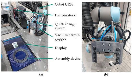
Figure 9.
(a) Test setup for collaborative assembly of hairpins; (b) Additively manufactured vacuum gripper.
3.2. Test Setup for Collaborative Hairpin Assembly
Figure 9a shows the entire test setup. A cobot UR3e (Teradyne Robotics (Germany) GmbH, München, Germany) with a quick-change system SWS-007 (SCHUNK SE & Co. KG, Lauffen/Neckar, Germany) is used, on which the vacuum gripper is mounted. The vacuum is generated with an ejector VN-10-H-T3-PQ2-VQ2-RO1 (Festo Vertrieb GmbH & Co., KG, Esslingen, Germany). A screen protected by a plexiglass panel is embedded in the assembly table and provides visual support for the worker. The cobot picks up the hairpins according to the assembly sequence and hands them to the worker for assembly. The assembly device, into which the hairpins are assembled manually, is located directly above the display on the table. The operator can confirm actions via a keyboard. The software for the visual display and for controlling the assembly sequence runs on a ThinkCentre with 32 GB RAM (Lenovo (Deutschland) GmbH, Stuttgart, Germany).
In the current test setup, two different hairpin shapes can be processed to keep complexity low. As is common in industrial applications, they are mounted on rods. In the case of an industrial production line, these rods could be refilled directly from the hairpin bending machine. Future expansion is easily possible within the range of the cobot arm.
3.3. Software for Visual Support
The software developed has two tasks in the new approach. Firstly, it supports the worker during the assembly process and ensures that the correct hairpins are placed in the correct position. Secondly, it can be used during commissioning of the process by supporting the worker in planning the correct assembly sequence for the hairpins. This is implemented by a collision analysis of the winding, see Section 3.4.
Visual support for the operator is provided by three sections with different illustrations, see Figure 10. The basis of the collaborative assembly is the bottom section (Section 1), which shows the correct slot and position of both legs of the hairpin to be assembled in color. The assembly device is in the centre of the illustration. By pressing the space bar on the connected keyboard, the display is updated to show the correct position for the hairpin to be placed and the vacuum is switched off so that the hairpin can be easily removed from the gripper. During the assembly process by the worker, the cobot fetches the next hairpin for assembly. In section two, there is a 3D-representation of the hairpin basket that has been set up to that point. The hairpin currently to be set is highlighted in color. The 3D-model can be rotated and zoomed in using a mouse if required. The third section contains a list of the last three hairpins set, the current hairpin and the next three hairpins.
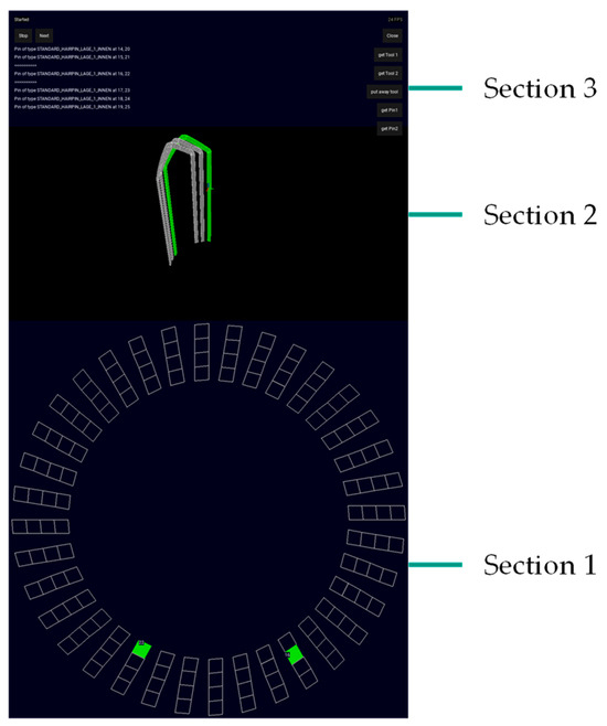
Figure 10.
Visual support for the pre-assembly of hairpins.
3.4. Software for Collision Detection
As already described, planning the assembly sequence is a complex process that also requires the planner’s experience. For this reason, an approach to automate the planning is being investigated. Based on a 3D-model of the complete hairpin basket, the winding scheme is first analyzed using collision detection. To do this, each hairpin is virtually pulled out of the 3D-model of the finished hairpin basket, and its collisions with other hairpins are detected and recorded. As the subsequent assembly movements by the worker will be either radially inwards or axially downwards, the hairpins are virtually pulled radially outwards and axially upwards. As an example, a section of a winding scheme is assumed in which layers 2 and 3 are occupied by special hairpins (e.g., jumpers, red), referred to as type A. Above these are special hairpins of type B whose legs are in layer 1 and layer 4 (blue). Top and side view of this section can be taken from Figure 11a. The radial collision analysis for the hairpins of type B shows a collision of the second leg in layer 1 with all other hairpins (type A and B) whose legs are in this slot. The axial collision analysis, on the other hand, only results in a collision with its neighboring hairpins of type B. No axial collision with type A is detected, which is a sign that type B can be assembled after type A in an axial way (axial collision analysis for type A results in detected collisions with type B). Radial assembly, on the other hand, is not possible for type B if type A is already assembled. However, as explained in Section 2.4, purely axial assembly is not possible due to mutual overlap of the type B hairpins. In this case, the rotation around the central axis (Figure 6b) offers a solution for collision-free assembling of the type B hairpins.
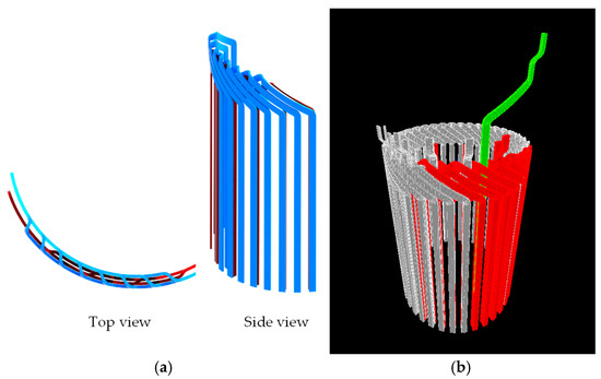
Figure 11.
(a) Winding scheme with special hairpins; (b) Screenshot of the collision detection program.
The collision analysis is carried out for each hairpin, resulting in an extensive table containing the collisions between all hairpins. In the current state, manual interventions are still necessary to determine the correct assembly sequence. However, the system can already be used as support for the assembly planer. The collision analysis is only used to determine possible assembly sequences. Collision monitoring of the entire process, including robots and workers, is not carried out.
Figure 11b shows a screenshot of the collision detection program. This illustration shows the collision of an I-pin during axial pullout. Based on the results of the collision analysis, the assembly sequence for collaborative assembly can be defined and recorded in a list. Based on this list, the robot feeds the correct hairpins, the exact position of which is shown on the display.
3.5. Hairpin Basket Gripper
The new hairpin basket gripper design is intended to significantly increase the flexibility of the gripper in terms of stator properties—particularly with regard to the number of slots. In addition, the set-up effort for new stator designs should be significantly reduced. For this reason, the concept presented does not use a large number of adjustable fingers to position the hairpins, as is the case with state-of-the-art grippers, see Section 2.7. Instead, the hairpins are fixed exclusively by radial clamping. As shown in Figure 12, there are two concepts to ensure the necessary precise tangential positioning of the hairpins. In both concepts, radial positioning is performed by the gripper.
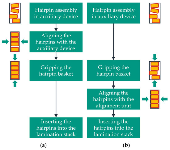
Figure 12.
Two concepts for gripping and aligning hairpin baskets with exclusively radial clamping: (a) Aligning the hairpins with the auxiliary device; (b) Aligning the hairpins with an alignment unit.
For the first concept, an auxiliary device can be designed for hairpin assembly, which allows the hairpins to be tangentially aligned once the hairpin basket has been correctly assembled, see Figure 12a. Three coaxially arranged rings with overlapping slots for mounting the hairpins would be conceivable, see Figure 13a. After assembly, the legs of the hairpins can be precisely aligned tangentially by turning the middle ring, see Figure 13b, before the hairpin basket is gripped, aligned radially and inserted into the lamination stack by the basket gripper. The corresponding hairpin basket gripper would be a mechanically simpler form of the gripper described below for concept (b) with only one gripping unit consisting of 6 gripper jaws. Since the aim of this work was to use an auxiliary device that was as simple as possible, this concept was not developed further.
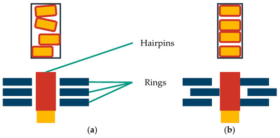
Figure 13.
Possible device for tangentially aligning the hairpin basket. (a) Slot before alignment; (b) Slot after alignment.
For the second concept, no special assembly device is required, see Figure 12b. Instead, a separate alignment unit is required in which each slot can be sequentially aligned in tangential direction. The concept is explained in detail in [14]. The hairpin basket gripper for this concept is based on two ring-shaped gripping units that can be rotated against each other. A gripping unit consists of six gripper jaws that can be adjusted radially and clamp the hairpins from the outside against an internal cylinder. This cylinder defines the inner radius of the hairpin basket. While all slots of the hairpin basket can be clamped by the upper gripping unit, one gripper jaw of the lower gripping unit has a recess so that the corresponding slot is not clamped. This particular slot is now guided into an alignment unit so that the hairpins are correctly aligned. All slots including the aligned slot are then clamped again by the upper gripping unit and the aligned slot is moved out of the alignment unit again. The entire hairpin basket gripper is then indexed forward by one slot (360°/N) and the lower gripping unit is indexed back accordingly. In this way, the hairpins of all slots are aligned one after the other in order to be inserted into the lamination stack afterwards. The hairpin basket gripper is attached to a robot that can move the hairpin basket in the alignment unit one slot after the other. The test setup is shown in Figure 14. The alignment unit is a metal 3D-print.
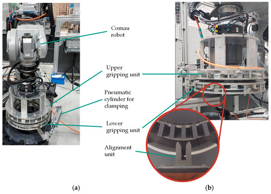
Figure 14.
(a) Test setup of the new hairpin basket gripper and sequential alignment; (b) Alignment unit and 3D-printed dummy hairpin basket seen from below.
The entire process chain is summarized again below and illustrated in Figure 15 using a 3D-printed dummy winding. The gripper and the hairpin basket are viewed from below.
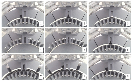
Figure 15.
Process chain for gripping and sequential alignment of the hairpin basket. The numbers indicate the corresponding process step.
- ▪ Step 1: Upper and lower gripping unit are closed.
- ▪ Step 2: The entire gripper is indexed forward by one slot.
- ▪ Step 3: The upper gripping unit is opened.
- ▪ Step 4: The gripper moves into the alignment unit. One slot is aligned.
- ▪ Step 5: The upper gripping unit is closed.
- ▪ Step 6: The gripper moves out of the alignment unit.
- ▪ Step 7: The lower gripping unit is opened.
- ▪ Step 8: The lower gripping unit is indexed backwards by one slot.
- ▪ Step 9: The lower gripping unit is closed and the process starts at step 2 again.
4. Results and Discussion
4.1. Collaborative Hairpin Assembly
Initial tests show that the presented concept of a collaborative hairpin assembly works in principle. Storing the hairpins on rods and gripping and handing the hairpins using the cobot and vacuum gripper are also possible. Communication between the Computer and the UR3e controller enables the cobot to respond flexibly to inputs via the keyboard. Figure 16 shows the collaborative hairpin assembly process. First, the cobot picks up the correct hairpin gripper (a). It then picks up a hairpin from the rod (b) and hands it to the worker (c). The worker takes the hairpin and places it in the auxiliary device according to the visual guidance (d).
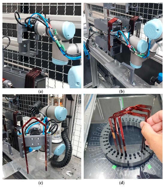
Figure 16.
Collaborative hairpin assembly process: (a) Picking up the correct hairpin gripper; (b) Picking up a hairpin; (c) Handing the hairpin to the worker; (d) Visually guided assembly of the hairpin.
At the moment the cycle time of the cobot to feed a new hairpin is 17 s, which is slower than the assembly process by the worker, especially at the start of the assembly, as there are only a few hairpins already set that need to be taken into account. The process time for an entire stator scales with the number of its hairpins. For a stator with 48 slots and 6 layers, and therefore at least 144 hairpins, this results in a process time of more than 40 min, which is unacceptable for an industrial use. As there has been no focus on optimising cycle times to date, a series of measures will be implemented in the future to significantly reduce them. Firstly, the speed of the cobot can be increased further, but it is important to ensure that the hairpin can still be gripped securely and that safety aspects relating to the worker are considered. Secondly, the cobot’s trajectory can be improved, for example by smoothing the robot path. In addition, the layout can be adjusted to optimize moving distances. However, the greatest potential for savings is seen in speeding up the gripping process itself, since this has accounted for a significant part of the total processing time. To ensure that individual hairpins can be gripped and removed safely from the rod, this process has been very slow up to now. A more efficient way of providing and gripping the hairpins therefore has great potential, but also means a lot of changes and improvements that may also affect the upstream process of hairpin bending in industrial applications. The described changes should cut the cycle time by at least half.
In addition to the current long cycle times, changeover times for the gripper must be taken into account, which are also in the range of approximately 20 s. The number of necessary changes is at least equal to the number of different hairpin shapes in the stator winding and increases if not all hairpins of one shape are assembled one after the other in the assembly sequence. A significant improvement in cycle time would be achieved by using a second robot, which would affect both the feeding of new hairpins and the tool change. In addition to increasing costs for the robot and a second tool set, the increasing complexity and space requirements are the main arguments against this option.
Even with the measures described above to reduce the cycle time, it is unlikely that the speed of the worker during the first, easy-to-assemble hairpins will be reached. Nevertheless, there are application scenarios in which collaborative assembly can be useful: The first scenario is the assembly of complex stator designs with many special hairpins. Automated solutions for this are complex, expensive, time-consuming and inflexible. Manual assembly is error-prone. In the second scenario, the standard hairpins of the winding are first assembled in an automated, fast process, as they are easy to assemble. The more complex and time-consuming assembly steps, usually involving the special hairpins, would then be carried out by the collaborative assembly process, completing the winding. Both application scenarios are particularly conceivable for small quantities and a wide variety of stator variants for which an automated solution is not worthwhile and manual assembly is error-prone.
Experimental tests have shown that the operability of the current system is acceptable and intuitive, but mouse and keyboard are impractical for industrial use. Instead of the keyboard, a simple switch is to be used in future to enable the assembly program to be continued. Using the 3D-model in the middle of the display is particularly useful for better orientation when training new employees or new winding patterns. Active use of the model (in the sense of rotating and zooming) during the ongoing production process is also rather unlikely for time reasons, which is why the mouse can be retained but does not have to be permanently available to the worker. Errors, e.g., if the worker accidentally drops or bends a hairpin during assembly, are not yet taken into account in the system. However, implementing a corresponding response from the system, e.g., supplying the worker with another hairpin of the same type, is considered feasible.
The display supports the worker during the assembly process, as he does not have to determine the assembly sequence and hairpin shape to be assembled himself using lookup-tables. The correct assignment of hairpin shape and position of the two legs is clearly indicated by the software, the cobot and the display. Even if the system does not currently detect incorrect placement of the hairpin, this significantly reduces the number of possible errors.
The collision detection approach shows promising results, which have already been tested for some hairpin topologies and winding schemes. The collision detection algorithm itself works in both the radial and axial directions. The correct assembly sequence can then be derived from the results of the collision analysis for certain, simply structured sections of the hairpin basket. An example is given in Section 3.4. However, it can currently only be used to support the operator in the planning process and not to automatically generate the entire assembly sequence, especially in case of complex winding schemes. For example, the first hairpin to be assembled must be specified by the user, and optimized planning, in which different assembly sequences are tested, has not been implemented. So far there is also no additional information about the correct movement required to assemble the hairpin collision-free (see Figure 6b). This information is particularly lacking for the last hairpins to be set in complex winding schemes, where it would be useful to support the operator.
Table 1 summarizes the final evaluation of the approach in comparison to manual and automated assembly. As described, the new approach can reduce the susceptibility to errors compared to manual assembly, while the cycle time in particular still needs to be improved. Flexibility is slightly reduced compared to manual assembly, as the grippers must be replaced for new stator designs, for example. The costs can only be estimated qualitatively for manual and automated assembly. Provided that the cycle time is reduced in the future, the approach presented is therefore particularly useful for complex winding schemes, small quantities, and a high degree of variant diversity. In these scenarios, the disadvantages in terms of flexibility and cycle time can be offset by a lower susceptibility to errors thanks to visual support for the operator. For highly complex winding patterns, the cycle time can even be improved compared to manual assembly, as there is no need for time-consuming assembly based on lookup tables.

Table 1.
Comparison of the new collaborative assembly with the manual and automated process.
4.2. Hairpin Basket Gripper and Sequential Alignment
The new approach for gripping hairpin baskets and aligning the hairpins in a sequential process was tested using a stator with 48 slots and 6 layers. Even though the concept works in principle, it still has some issues to deal with. Especially if the hairpin basket has a lot of play in the assembly device, the initial position of the hairpins in the basket gripper is already so poor that sequential alignment is hardly possible, see Figure 17a–c. Nevertheless, the hairpin basket is gripped securely even in this case and the hairpins do not move axially. If the play in the assembly device is reduced, the initial position of the hairpin legs is also significantly better (see Figure 17d) and they can be moved securely into the alignment unit. For this reason, it is conceivable to combine an auxiliary device that can align the hairpins tangentially (Figure 12a) with a gripper consisting of only one gripping unit with 6 gripper jaws. Sequential alignment would not be necessary in this case.
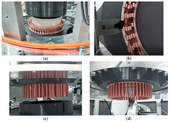
Figure 17.
(a) Winding head of a gripped hairpin basket with low positional accuracy; (b) Hairpin legs of a gripped hairpin basket with low positional accuracy (from below); (c) Hairpin legs of a gripped hairpin basket with low positional accuracy (side view); (d) Hairpin legs of a gripped hairpin basket with high positional accuracy (side view).
It was found in the tests that the hairpins partially slip back into their original position before alignment as soon as they leave the alignment unit. The 3D-printed gripper jaws were identified as a possible cause, as they tilt slightly downwards when closing under high pressure, so that instead of surface pressure there is only line load.
Table 2 compares the novel approach with state-of-the-art grippers. Flexibility was increased as desired. The gripper is independent of the number of slots and wire geometry. If the stator diameter changes, only 12 gripper jaws need to be replaced instead of a number of fingers corresponding to the number of slots, e.g., 72. As described above, the approach is still very error-prone, especially if the hairpins in the auxiliary device have a lot of play. Unlike the cycle time for state-of-the-art grippers, it depends directly on the number of slots. With several seconds per slot alignment, this currently results in a cycle time of several minutes to pick up the hairpin basket, align every slot and transport it to the lamination stack. The cost of the novel gripper is approximately €15,000, which is considered to be significantly lower than state-of-the-art grippers, even though exact figures are not available. This does not include the robot currently in use, which is significantly more expensive than the linear axes normally used. Since the robot can also be used for further steps, such as sequential twisting [18], this is not considered here. Due to the low number of parts that need to be replaced, the setup costs for changing to a new stator design are also significantly lower.
Table 2.
Comparison of the new gripper design with state-of-the-art grippers.
5. Conclusions
The manual and automated assembly of hairpins into a hairpin basket both have advantages and disadvantages. While manual assembly is flexible due to the use of workers, it is very prone to errors. Automated assembly, on the other hand, can offer short cycle times and a high level of safety, but it is inflexible at the same time. The collaborative assembly presented here is intended to combine the advantages of both approaches and avoid the disadvantages. For this purpose, a cobot is used to hand the worker the correct hairpins. Visual support on a display located under the assembly device shows the worker the correct position of the hairpin. Tests have shown that collaborative assembly is possible and significantly reduces the susceptibility to errors. However, the current cycle time of 17 s is problematic. Creating an assembly sequence can be facilitated by the presented analysis using collision detection. At present, however, this is only a planner’s aid; a complete assembly sequence cannot yet be derived from it.
The basic functionality of the hairpin basket gripper with a sequential alignment process was successfully tested. The kinematics and the alignment unit worked as intended. However, there are still challenges to be solved, particularly when it comes to correctly clamping the hairpins so that they keep their aligned position. To solve this problem, the additively manufactured gripper jaws will be replaced with ones made of aluminum. Right now the process can only be used under the condition that the hairpins are already well aligned in the assembly device before gripping. A combination of an auxiliary device that can align the hairpins tangentially with a gripper consisting of only one gripping unit is conceivable; see Section 3.5 concept (a). Due to the solely radial gripping and the low number of moving parts (only six gripper jaws), there would be an even bigger advantage over state-of-the-art grippers with a large number of gripper fingers—particularly in terms of flexibility and set-up time. The disadvantage of this concept is the more complex mechanical auxiliary device for hairpin assembly, which is why it was not examined in detail in this study. Further tests and design adjustments to stiffen the mechanics are planned in order to make the process more robust.
In conclusion, it can be said that both approaches have clear weaknesses in terms of cycle time, but significantly improve error susceptibility (collaborative assembly) and flexibility (basket gripper). For this reason, they are particularly suitable for use in prototype construction or small series production.
Author Contributions
Conceptualization, F.F.; Data curation, F.F., J.L. and D.R.; Formal analysis, F.F. and J.L.; Funding acquisition, J.F.; Investigation, F.F. and J.L.; Methodology, F.F. and J.L.; Software, P.D., J.L. and D.R.; Supervision, J.F.; Validation, F.F. and J.L.; Visualization, F.F.; Writing—original draft, F.F.; Writing—review & editing, F.K. and J.F. All authors have read and agreed to the published version of the manuscript.
Funding
The authors gratefully acknowledge financial funding from the German Federal Ministry of Economic Affairs and Climate Action and the European Union (grant no. 13IK003H) as well as organizational support by the VDI Technologiezentrum GmbH.
Data Availability Statement
The datasets presented in this article are not readily available because the data are part of an ongoing study. Requests to access the datasets should be directed to the corresponding author.
Conflicts of Interest
The authors declare no conflicts of interest. The funders had no role in the design of the study; in the collection, analyses, or interpretation of data; in the writing of the manuscript; or in the decision to publish the results.
Abbreviations
The following abbreviations are used in this manuscript:
| N | Number of slots |
| L | Number of layers |
References
- Berardi, G.; Nategh, S.; Bianchi, N.; Thioliere, Y. A Comparison Between Random and Hairpin Winding in E-mobility Applications. In Proceedings of the IECON 2020 the 46th Annual Conference of the IEEE Industrial Electronics Society, Singapore, 18–21 October 2020; pp. 815–820. [Google Scholar] [CrossRef]
- Kuehl, A.; Riedel, A.; Vogel, A.; Hartl, S.; Glaessel, T.; Masuch, M.; Franke, J. Robot-based Production of Electric Motors with Hairpin Winding Technology. In Proceedings of the International Conference on Intelligent Automation and Robotics (ICIAR’19), San Francisco, CA, USA, 22–24 October 2019; pp. 257–262. [Google Scholar]
- Fraider, F.; Dreher, P.; Reichl, D.; Kößler, F.; Fleischer, J. Collaborative Assembly of Hairpin Coils. In Proceedings of the EVS37 Symposium, Seoul, Republic of Korea, 23–26 April 2024. [Google Scholar]
- Riedel, A.; Masuch, M.; Weigelt, M.; Gläßel, T.; Kühl, A.; Reinstein, S.; Franke, J. Challenges of the Hairpin Technology for Production Techniques. In Proceedings of the 2018 21st International Conference on Electrical Machines and Systems (ICEMS), Jeju, Republic of Korea, 7–10 October 2018; pp. 2471–2476. [Google Scholar] [CrossRef]
- Kampker, A.; Heimes, H.; Kawollek, S.; Treichel, P.; Kraus, A. Production Process of a Hairpin Stator, 2nd ed.; PEM of RWTH Aachen University and VDMA own print: Frankfurt am Main, Germany, 2020. [Google Scholar]
- Berardi, G.; Bianchi, N. Design Guideline of an AC Hairpin Winding. In Proceedings of the 2018 XIII International Conference on Electrical Machines (ICEM), Alexandroupoli, Greece, 3–6 September 2018; pp. 2444–2450. [Google Scholar] [CrossRef]
- Zou, T.; Gerada, D.; La Rocca, A.; Moslemin, M.; Cairns, A.; Cui, M.; Bardalai, A.; Zhang, F.; Gerada, C. A Comprehensive Design Guideline of Hairpin Windings for High Power Density Electric Vehicle Traction Motors. IEEE Trans. Transp. Electrif. 2022, 8, 3578–3593. [Google Scholar] [CrossRef]
- Zhao, Y.; Li, D.; Pei, T.; Qu, R. Overview of the rectangular wire windings AC electrical machine. CES Trans. Electr. Mach. Syst. 2019, 3, 160–169. [Google Scholar] [CrossRef]
- Dannier, A.; Di Bruno, F.; Fiume, F.; Fedele, E.; Brando, G. Hairpin Winding Technology for Electric Traction Motors: Design, Prototyping, and Connection Rules. In Proceedings of the 2022 International Conference on Electrical Machines (ICEM), Valencia, Spain, 5–8 September 2022; pp. 1170–1175. [Google Scholar] [CrossRef]
- Zhang, W.; Wu, Z.; Hua, W. Design of n-Layer Flat Wire Winding in Permanent Magnet Machine for Electric Vehicles. IEEE Trans. Transp. Electrif. 2025, 11, 7798–7810. [Google Scholar] [CrossRef]
- Mahr, A.; Mayr, A.; Jung, T.; Franke, J. Robot-assisted concept for assembling form coils in laminated stator cores of large electric motors. Procedia Manuf. 2019, 38, 866–875. [Google Scholar] [CrossRef]
- Hüttner, T.; Scheeff, S. Device, Machine and Method for Producing a Final Configuration of Conductor Elements. WO 2023/061664 A1, 20 April 2023. [Google Scholar]
- Okuda, S.; Ohno, K.; Omagari, K. Alignment Method and Apparatus for Electric Conductors. U.S. Patent 10923993 B2, 16 February 2021. [Google Scholar]
- Fraider, F.; Wustmann, E.; Fleischer, J. Approach for Flexible Gripping and Sequential Alignment of Hairpin Baskets. In Proceedings of the 2023 13th International Electric Drives Production Conference (EDPC), Regensburg, Germany, 29–30 November 2023; pp. 1–7. [Google Scholar] [CrossRef]
- Fraider, F.; Baranowski, M.; Gerner, J.; Cassiani, C.; Geis, P.; Wirth, F.; Fleischer, J. Additively manufactured vacuum grippers for the flexible handling and assembly of hairpin coils in electric motor production. Procedia CIRP 2024, 127, 8–13. [Google Scholar] [CrossRef]
- Cavallini, A. High Power Density Motors for Transport Electrification: State-of-the-Art and Challenges. In Proceedings of the 2024 10th International Conference on Condition Monitoring and Diagnosis (CMD), Gangneung, Republic of Korea, 20–24 October 2024; pp. 238–241. [Google Scholar] [CrossRef]
- Fraider, F.; Koessler, F.; Fleischer, J.; Dreher, P.; Gerstner, A. Investigation of the Influence Parameters on the Joining Force of the Hairpin Coil Insertion Process. In Proceedings of the 2024 14th International Electric Drives Production Conference (EDPC), Regensburg, Germany, 26–27 November 2024; pp. 1–7. [Google Scholar] [CrossRef]
- Hausmann, L.; Wirth, F.; Fleischer, J. Flexible Twisting Process of Stators with Hairpin Winding. In Proceedings of the 2022 12th International Electric Drives Production Conference (EDPC), Regensburg, Germany, 29–30 November 2022; pp. 1–9. [Google Scholar] [CrossRef]


Disclaimer/Publisher’s Note: The statements, opinions and data contained in all publications are solely those of the individual author(s) and contributor(s) and not of MDPI and/or the editor(s). MDPI and/or the editor(s) disclaim responsibility for any injury to people or property resulting from any ideas, methods, instructions or products referred to in the content. |
© 2025 by the authors. Published by MDPI on behalf of the World Electric Vehicle Association. Licensee MDPI, Basel, Switzerland. This article is an open access article distributed under the terms and conditions of the Creative Commons Attribution (CC BY) license (https://creativecommons.org/licenses/by/4.0/).