Article

Design and Implementation of a Teaching Model for EESM Using a Modified Automotive Starter-Generator

Department of Mechatronics and Electronics, FEIT, University of Žilina, 010 26 Žilina, Slovakia
*
Author to whom correspondence should be addressed.
World Electr. Veh. J. 2025, 16(9), 480; https://doi.org/10.3390/wevj16090480
Submission received: 23 July 2025 / Revised: 20 August 2025 / Accepted: 20 August 2025 / Published: 22 August 2025

Abstract

This project presents the development of an open-source educational platform based on an automotive Electrically Excited Synchronous Machine (EESM) repurposed from a KIA Sportage mild-hybrid vehicle. The introduction provides an overview of hybrid drive systems and the primary configurations employed in automotive applications, including classifications based on power flow and the placement of electric motors. The focus is placed on the parallel hybrid configuration, where a belt-driven starter-generator assists the internal combustion engine (ICE). Due to the proprietary nature of the original control system, the unit was disassembled, and a custom control board was designed using a Texas Instruments C2000 Digital Signal Processor (DSP). The motor features a six-phase dual three-phase stator, offering improved torque smoothness, fault tolerance, and reduced current per phase. A compact Anisotropic Magneto Resistive (AMR) position sensor was implemented for position and speed measurements. Current sensing was achieved using both direct and magnetic field-based methods. The control algorithm was verified on a modified six-phase inverter under simulated vehicle conditions utilizing a dynamometer. Results confirmed reliable operation and validated the control approach. Future work will involve complete hardware testing with the new control board to finalize the platform as a flexible, open-source tool for research and education in hybrid drive technologies.

1. Introduction

In recent decades, global warming has become a serious problem [1,2]. The solution to this problem is the reduction of CO2 and other greenhouse gases. Global targets for reducing CO2 emissions are designed to keep global warming below 1.5 °C [3,4]. To achieve this, emissions must be cut by 45% from 2010 levels by 2030, reduced by 90% by 2040, and reach net-zero by 2050. To achieve these goals, greenhouse gas emissions must be reduced in several key segments. One significant contributor to greenhouse gas emissions is transportation, which accounts for approximately a quarter of total emissions [5]. Reducing the production of greenhouse gases in transportation through the use of electric vehicles and hybrid electric vehicles is crucial. Hybrid cars have gained popularity due to their lower fuel consumption and improved performance compared to ICE. One disadvantage of hybrid electric vehicles is the higher price of the car. Additionally, grid infrastructure has not yet been scaled to accommodate the rapid growth of electric vehicles, although some charging algorithms have been developed to address this issue [6].
There are several types of hybrid electric vehicles, which can be categorized by the flow of energy or placement of the electric motor, as shown in Figure 1 [7,8].
The flow of power means that the power of the internal combustion engine and the electrical motor work together. In a parallel configuration, for vehicle drive, both an electrical motor and an internal combustion engine are used [8,9]. Based on the placement of the electric motor, each type of drive can be used individually, allowing the long drive range of the ICE to be utilized. In a series hybrid, the combustion engine powers the first electric motor, which in turn charges the batteries. The second electric machine, powered by batteries, is used for vehicle propulsion [8]. The advantage of downsized ICE is that it is used only for charging batteries and can operate over a range of rotations per minute (RPM), producing the lowest greenhouse gas emissions and consumption. The last configuration is a combination of the previous configurations [10]. The advantage of this configuration is the potential for the most efficient control of the hybrid driveline; however, the drawback is its mechanical complexity.
The second criterion of division is the placement of the electric motor in a parallel hybrid. There are five main categories, but their combinations are also possible [9,10]. The available placement of the electric motor is shown in the block diagram of Figure 2.
Table 1 shows the features of every hybrid type according to the electric motor placement in the system:
The first type is P0, where an electric motor is used as a starter-generator with a combustion engine. The disadvantage of this type is that the electric motor is always mechanically connected to the combustion engine; thus, pure electric drive is not possible. The advantage is that an electric motor can deliver peak power and torque, allowing the combustion engine to be downsized [10,11]. The second type is P1, where the electric motor is placed directly on the crankshaft of the combustion engine. The advantage of P1 is similar to that of P0, but this configuration has one additional disadvantage. Between motor and engine, there is no gearing; thus, the speeds of the engine and the electric motor are the same. The next type, type P2, features an electric motor positioned after the clutch of the ICE, allowing for electric drive without using the ICE. In the Fourth type, type P3, the electric motor is placed after the transmission, allowing for a pure electric drive. However, the motor must be designed to drive the prop shaft or driveshaft. The type, P4 and P5, powers the axle or wheels directly. These types are also called hybrid through-road because the mechanical connection between the ICE and the electric motor is with the wheels [11,12]. That means that the most significant advantage is a 4 × 4 drive.
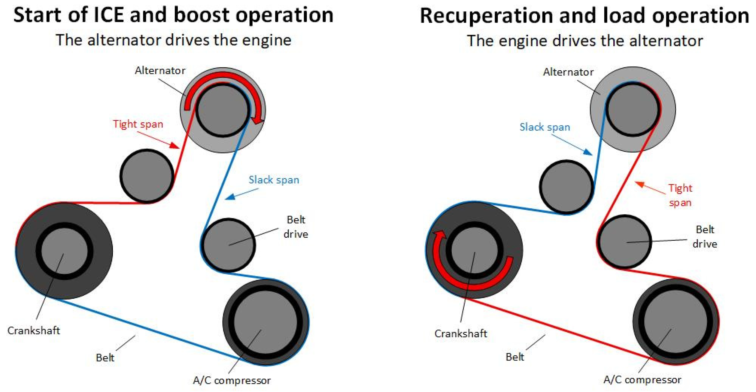
In this paper, we focus on the parallel hybrid in configuration P0, specifically a belt-driven starter-generator. This type of hybrid is most common because it is the easiest to implement, as shown in Figure 3. A Standard alternator, which is used for charging a 12 V battery, is replaced with a machine that can work as both a generator for charging the battery and a motor. Motoric mode is used during the start of ICE and rapid vehicle acceleration. The power of the electric machine is limited by the slip of the belt that is used for powering. During operation, based on the mode of the electric machine, the belt must be tensioned in the direction of torque, as also demonstrated in Figure 3 [13,14,15].
Due to the relatively high power—around 10 kW—for these starter generators, a 48 V system is used to reduce the current. A 48 V system can be utilized in other systems, such as adaptive suspension, electric turbochargers, and other vehicle systems that require high power. For starter generators, two types of electric machines can be used: Electrically Excited Synchronous Machines (EESM) and Permanent Magnet Synchronous Machines (PMSM) [16,17]. EESMs are gaining significant attention in recent years as viable alternatives to PMSM and Induction Machines (IM). They can be more advantageous in applications where precise control, field weakening, and cost-effective scalability are required [18,19,20,21,22].
In this project, the authors repurposed an automotive starter-generator, which was initially equipped with its control board. Due to the lack of documentation and interface support, the authors removed the original control electronics and designed a custom control board that directly interfaces with the power transistors. The goal of this project is to develop an educational EESM Starter-Generator (SG) model that demonstrates key principles of excitation control and energy conversion in conjunction with the combustion engine. The SG is mounted on the ICE and connected to the motor output using a V-belt. This connection enables the SG to operate dynamically in both modes—generator or motor—depending on the actual system requirements. During the engine’s start-up, the SG serves as a motor, delivering the required torque to crank the ICE. Once the engine is running, SG can operate as a generator, converting mechanical energy to electrical and storing this energy for later use, or can be operated as a motor, where it can help the ICE in particular conditions, such as low RPM drive, boosting the ICE operation, or lowering the emissions of the engine. This dual functionality makes the SG a key component in mild hybrid systems with start-stop technology, where seamless mode switching is essential. The use of the V-belt enables a flexible mechanical coupling, allowing for the simple integration of the system into existing engine layouts.

2. EESM Background

EESMs are a class of synchronous machines where the magnetic field required for the operation is generated by a field winding of the rotor, rather than by permanent magnets [18,21]. The rotor winding is typically supplied with Direct Current (DC) power via slip rings and brushes, enabling the creation of a controllable magnetic field. This field can interact with the stator’s rotating magnetic field produced by the Alternating Current (AC) supply. The key advantage of the EESM lies in the ability to actively control rotor excitation, which is crucial in start-stop applications. Field control enables variable flux operation of the machines, making it more suitable for a wider operating range, including the mentioned field weakening regions. Compared to the PMSM, EESM offers several benefits:
-
It is cost-effective because it has no reliance on rare-earth materials
-
Because of no magnets, EESM is better in high-temperature environments
-
Field weakening is easier to achieve due to active field control
However, these mentioned benefits come at the cost of added system complexity, primarily due to the need for a separate excitation system and slip ring maintenance. But in a global view, advances in power electronics and digital control have made EESMs more practical and accessible for the everyday user of hybrid vehicles [22,23,24,25].

3. Proprietary EESM System

EESM used in this project originates from the KIA Sportage Mild-Hybrid and is manufactured for KIA by VALEO [26,27].
This unit is part of a tightly integrated closed system shown in Figure 4, optimized for seamless communication with the Engine Control Unit (ECU). Unfortunately, no technical documentation, communication protocols, or control interfaces were made publicly available. The car manufacturer cannot share this information due to intellectual property protection. Another way to gain control of the EESM unit was to listen to the Controlled Area Network (CAN) communication of the car and attempt to reverse-engineer the EESM communication protocol.
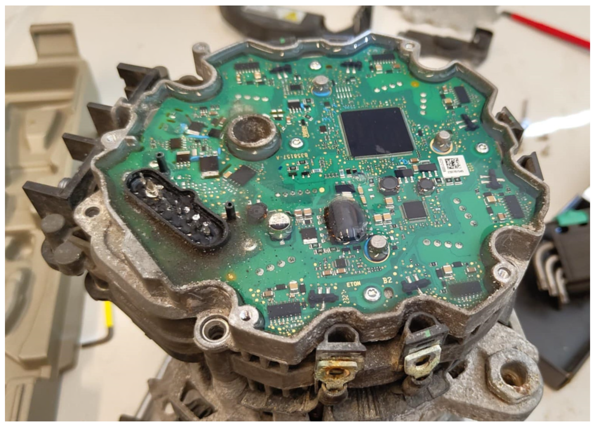
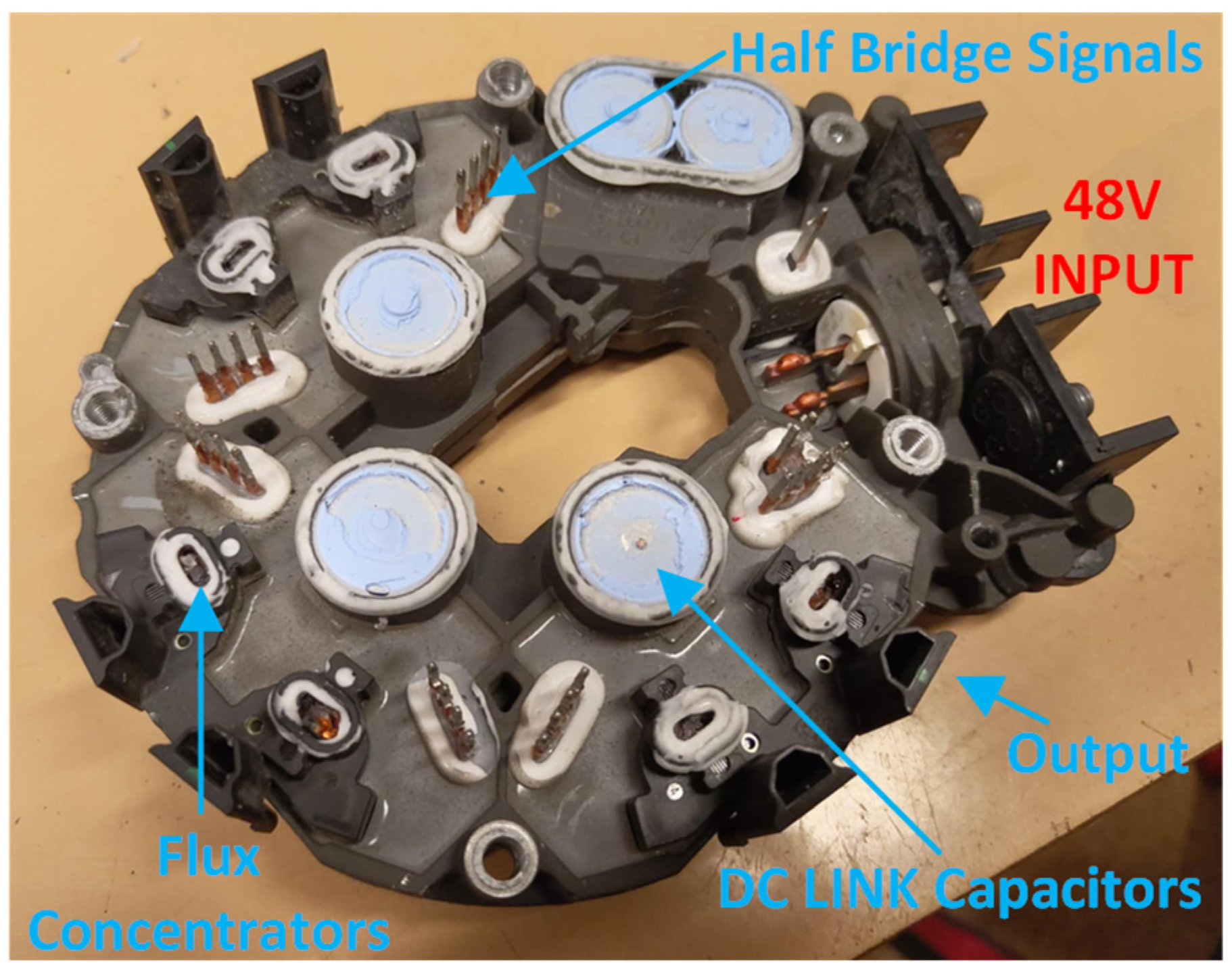
This would involve capturing CAN messages exchanged during the various operating states (starting, idling, charging, motor boosting, and so on). However, this method is highly time-consuming and complex, as multiple ECUs communicate simultaneously. Therefore, each operating scenario needs to be studied separately. Decoding the meaning of the frames without documentation is a laborious process, and communication could be encrypted due to Intellectual Property (IP) protection. Given these constraints, a more direct and flexible solution was chosen. Physically disassemble the unit and remove the factory-installed control board, as shown in Figure 5.
This allows access to the machine power stage, primarily control signals of the output transistors, and enables the design of a custom control system based on the system we know. By passing the original electronics, control over rotor excitation and stator currents was gained, transforming the EESM into an open platform for educational and experimental purposes. It is essential to notice that the mentioned EESM from the KIA is a 6-phase motor. The configuration is dual three-phase stator winding mechanically shifted by 30°, as shown in Figure 6. The six-phase motor comes with a more complex control system, but it offers some significant advantages:
-
Increased fault tolerance: In the event of failure in one of the three-phase subsystems, the motor can still be operational, but with reduced power [28].
-
Lower per-phase current: Due to the dual three-phase configuration, phase current can be significantly lower while maintaining the same overall torque output.
-
Smoother torque production: The 30° shift between three-phase systems contributes to the smoother torque production, reducing torque ripple. This reduces stress on the mechanical components, thereby increasing the system’s performance and lifespan.
The primary objectives of the design are to create a new control board that can interface with the existing power stage on the EESM. The new control board will be based on the Texas Instruments C2000 platform due to the extensive knowledge of their DSPs. Another challenge in synchronous motor control is position sensing. Because the Field Oriented Control (FOC) will be used, the position of the rotor must be known. The system had a built-in encoder, but it lacked a serial number, and the sensor was unidentified. This leads to another challenge: designing a new position-sensing technique.

3.1. Rotor Position Sensor Design

As mentioned before, the rotor position is essential for motor control. There are multiple ways to sense rotor position, but in general, there are two categories:
-
Encoders: Output pulses according to the resolution of the sensor. This sensor is relatively cheap and can be interfaced directly by counting pulses and calculating the time between pulses [29,30]. The disadvantage is that the encoder does not know the absolute position of the rotor, and this position must be detected after every system power-up.
-
Resolvers: A more complex solution for position sensing, but it offers absolute rotor position. There are many types of resolvers based on their principle of operation [30].
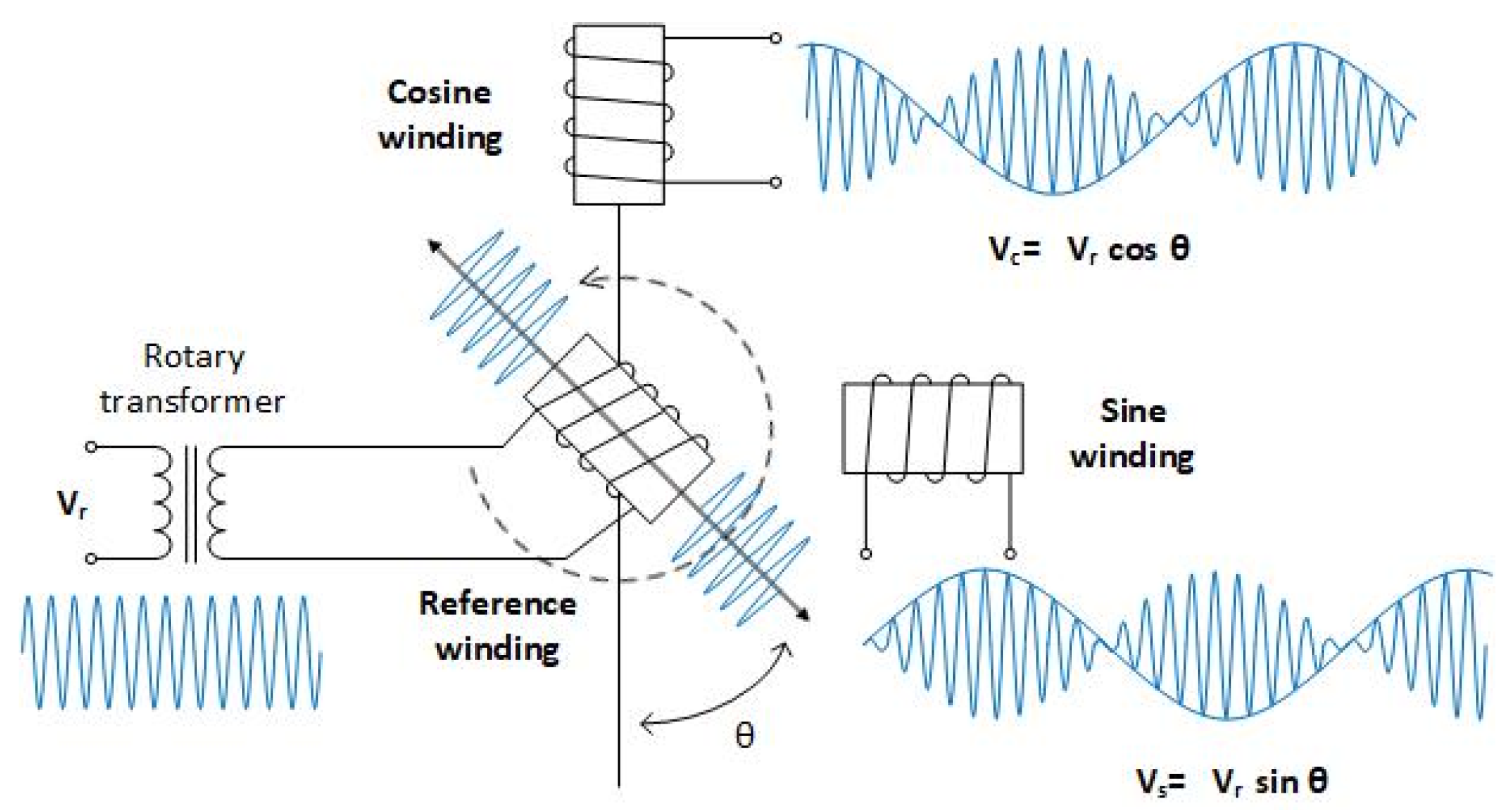
Aligning the motor rotor after every start-up with the use of the encoder can introduce unwanted disturbances to the system. Due to this limitation, the resolver was selected as the position sensor for this application. Standard resolvers, based on the transformer principle of operation, are the most common. There are three windings, excitation, and two sensing windings known as Sine and Cosine, due to their output shape as shown in Figure 7. This type of resolver requires relatively complex excitation circuits to inject a high-frequency sine wave into the excitation winding. Similarly, the variable reluctance resolver, now commonly used in most electric vehicles, is another option. However, due to their complex excitation system and physical dimensions, these types of sensors were ruled out as a possible solution.
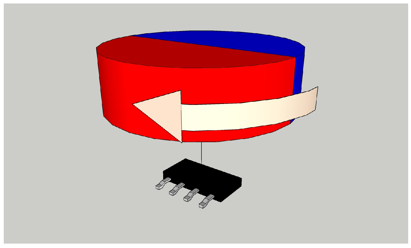
Due to improvements in the field of Anisotropic Magneto-Resistive (AMR) technology, new methods of position sensing are now available. In this solution, a high-precision magnetic angle sensor was employed. This technology utilizes diagonally magnetized neodymium magnets in conjunction with a suitable sensor. The sensor uses two AMR sensors, positioned 45° apart, which can generate sine and cosine outputs based on the magnet’s position [30]. A significant advantage of this solution is its compact dimensions and absence of excitation circuits, which significantly reduce the design complexity. The principle of position sensing using the AMR sensor is shown in Figure 8.
The used part is Texas Instruments TMAG6180 [31], available in a small TSSOP-8 package, which can be directly mounted on the control board. Then, a magnet needs to be mounted on the rotor shaft and positioned close to the sensor to properly measure the magnetic fields, as shown in Figure 9. The Sensor outputs two signals, sine and cosine, which are measured using the ADC of the DSP. From these values, the position of the rotor and its speed are calculated.
The sensor function and behavior were tested in parallel with the design of the new control PCB. This allows for a change in the sensor design if some errors arise during testing. For the initial motor testing, the inverter from the previous project was used [32]. The inverter is designed as a 6-phase T-type Neutral Point Clamped (TNPC) inverter with an output power of 100 kW. For this application, the middle transistors in the inverter were not used, and the inverter was configured as a standard 6-phase half-bridge inverter. Again, testing on this inverter was selected to verify the control algorithm before the new board is manufactured, to prevent some mistakes that can arise during the testing phase.

3.2. New Control PCB Design

For the proper control of the EESM, the new control board must contain the following subsystems:
-
6× Half Bridge drivers
-
1× Half-bridge driver for excitation winding
-
Isolated CAN communication
-
Implemented AMR position sensor
-
Control DSP
-
6× Current measurement for each phase
-
Voltage and temperature measurement
All these systems, together with the control DSP, must be implemented in a PCB with a fixed layout and dimensions. This is because we are fitting a PCB to the existing inverter; thus, the position of the control signals for the transistors must be preserved. Figure 10 shows the existing inverter assembly:
In the original design, the half-bridge drivers used a bootstrap driving method for the high-side drivers. This is a highly efficient and cost-effective solution for powering up high-side drivers, but it presents some challenges in the control circuit. Due to these challenges and the fact that this is a demonstration PCB, isolated DC/DC converters were used to power the high-side drivers. This is an expensive solution, but it serves the purpose well. Together, six half-bridge drivers are designed for the output phases, and one is designed for the rotor exciter winding; thus, this design requires seven isolated power supplies.
Another challenge in this design is measuring the phase currents. The phase currents can easily reach values of 100 ARMS per phase during the engine’s start-up. This current needs to be measured to ensure good regulation in FOC. This board is designed with two types of current measurement in mind:
-
Physical current sensor: The Board has an interface to measure current using a physical HALL current sensor. The sensor is capable of measuring a current of 120 A RMS. The disadvantage of this method is the size and the fact that the sensor is SMD, and all the current must flow through the dedicated PCB of the sensor.
-
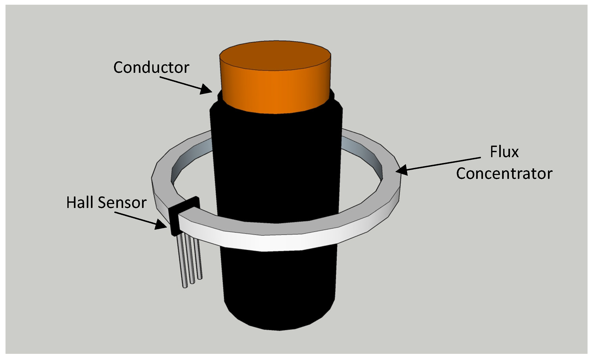
Ratiometric HALL Effect Sensor: Another ready solution is using a hall sensor with ratio-metric output. This sensor is put directly on the output phase conductor and measures the magnetic field. This value can be directly calculated for the following current. To further increase precision and sensitivity, the output phases have flux concentrators mounted on them, which improves the deployment of this measurement technique [33].
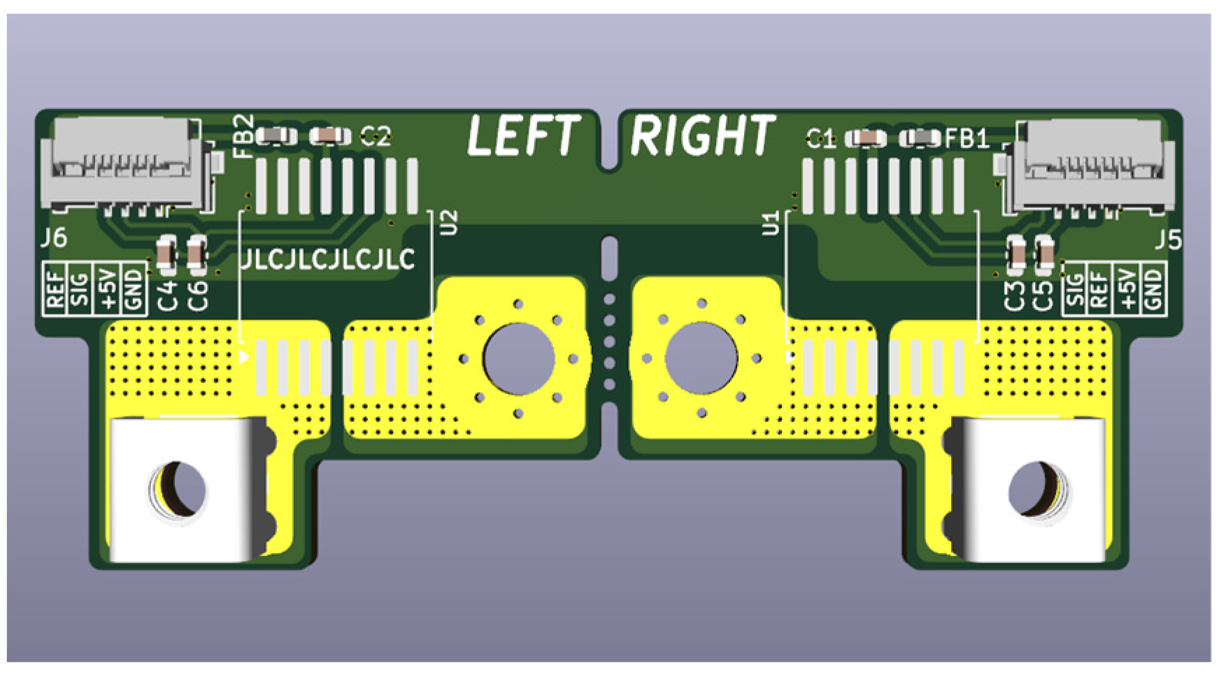
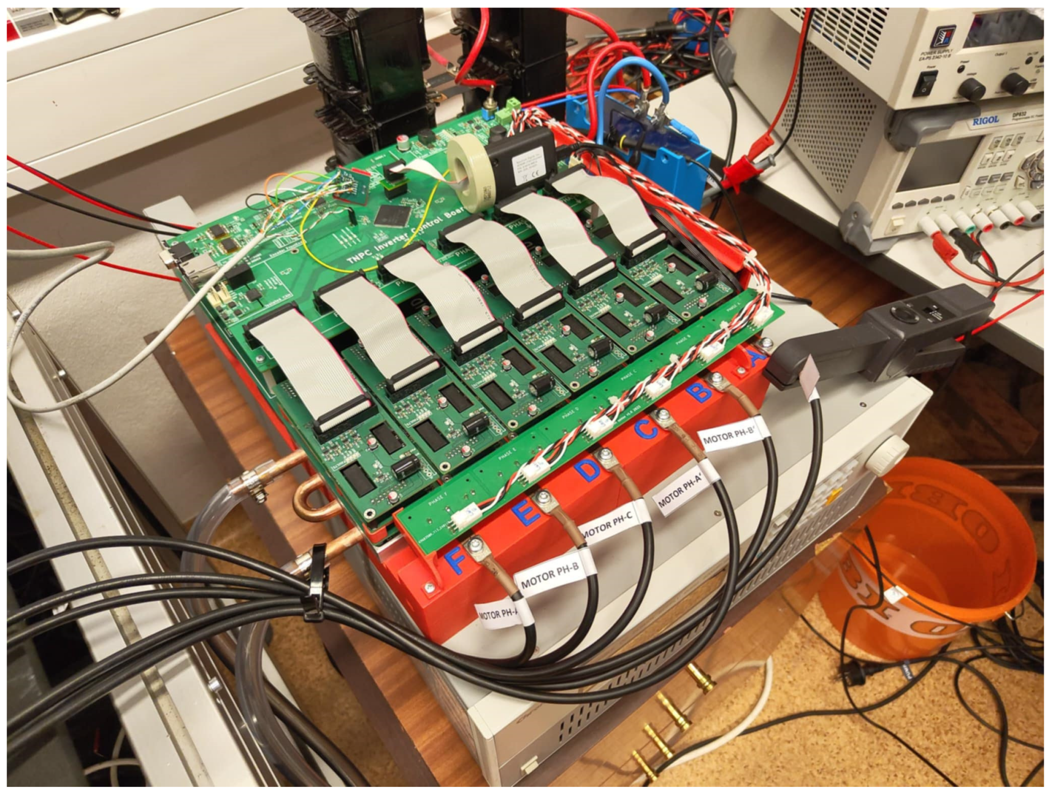
Two methods are designed on this board to demonstrate the possibilities of current measurement. The first solution shown in Figure 11 is relatively easy to implement; however, it places a significant amount of stress on the PCB and components. The second solution is exquisite, but it comes with its challenges, as shown in Figure 12.
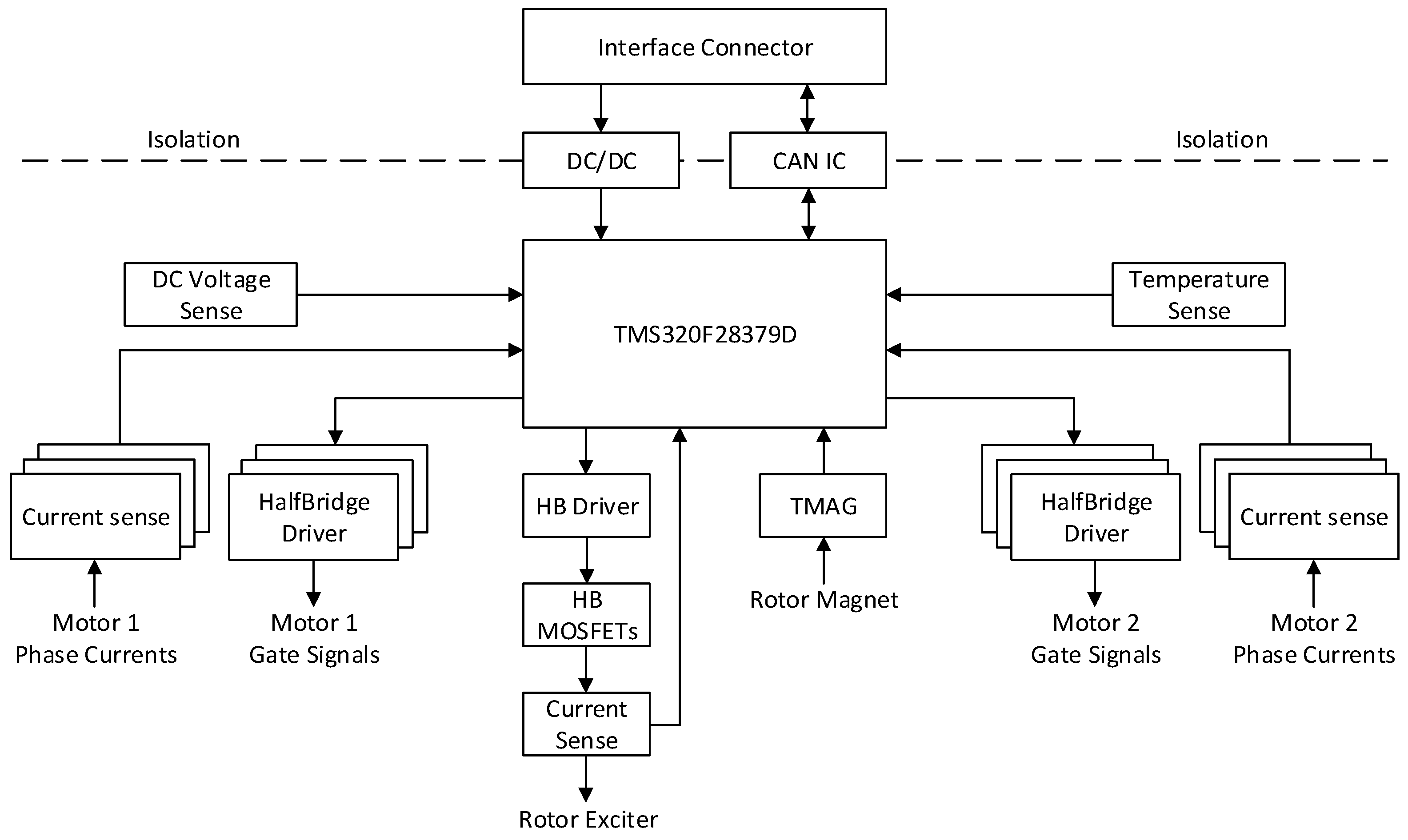
The block diagram in Figure 13 illustrates simplified components of the designed control board. The board comprises all the necessary circuits to control the dual three-phase windings of the EESM.
As mentioned before, the control PCB has a fixed layout and position of the signals, so components must be carefully selected to fit the available space. For easier debugging and implementation, most of the components are located at the top of the PCB. At the bottom, only passive components are located. For the control of the entire inverter, a dual-core DSP from Texas Instruments, the TMS320F28379D, was selected. This DPS offers a significant amount of computational power and a second core, which will be utilized for communication with the ICE ECU. The Top and Bottom sides of the designed PCB are shown in Figure 14:
The PCB is designed as a 6-layer PCB. This stack-up was selected due to the routing complexity and the large number of signals in the design. The bottom view of the PCB shows only passive components and the AMR sensor located in the middle of the PCB to interact with the magnet. Together with the position sensor, the six ratio metric sensors are positioned here to fit inside the flux concentrators in the inverter assembly.

4. EESM Verification with Another Inverter

During the design process, as mentioned earlier, the TNPC inverter, modified for our purposes, was used (Figure 15). This inverter is designed for high-voltage applications. It is capable of 950 VDC/100 ARMS/100 kW. For purposes of this project, the inverter was supplied by the 48 V power supply and was used to supply EESM. The first limitation of this inverter is the current sensors, which are designed only for 100 A RMS (141 A peak). The second limitation is power transistors. Because the inverter was initially designed for high-voltage applications, the SiC transistors are used. They have relatively high channel resistance (RDSON), which limits the inverter’s usage in high-current regions due to high power losses. Due to this limitation, monitoring the inverter’s temperature is crucial to avoid overloading the power modules.
The inverter utilizes the same control DSP, TMS320F28379D, as the newly designed control board. Thus, implementing the control algorithm will be significantly easier for the new control board, given the same DSP. The inverter assembly for testing is shown in Figure 16.
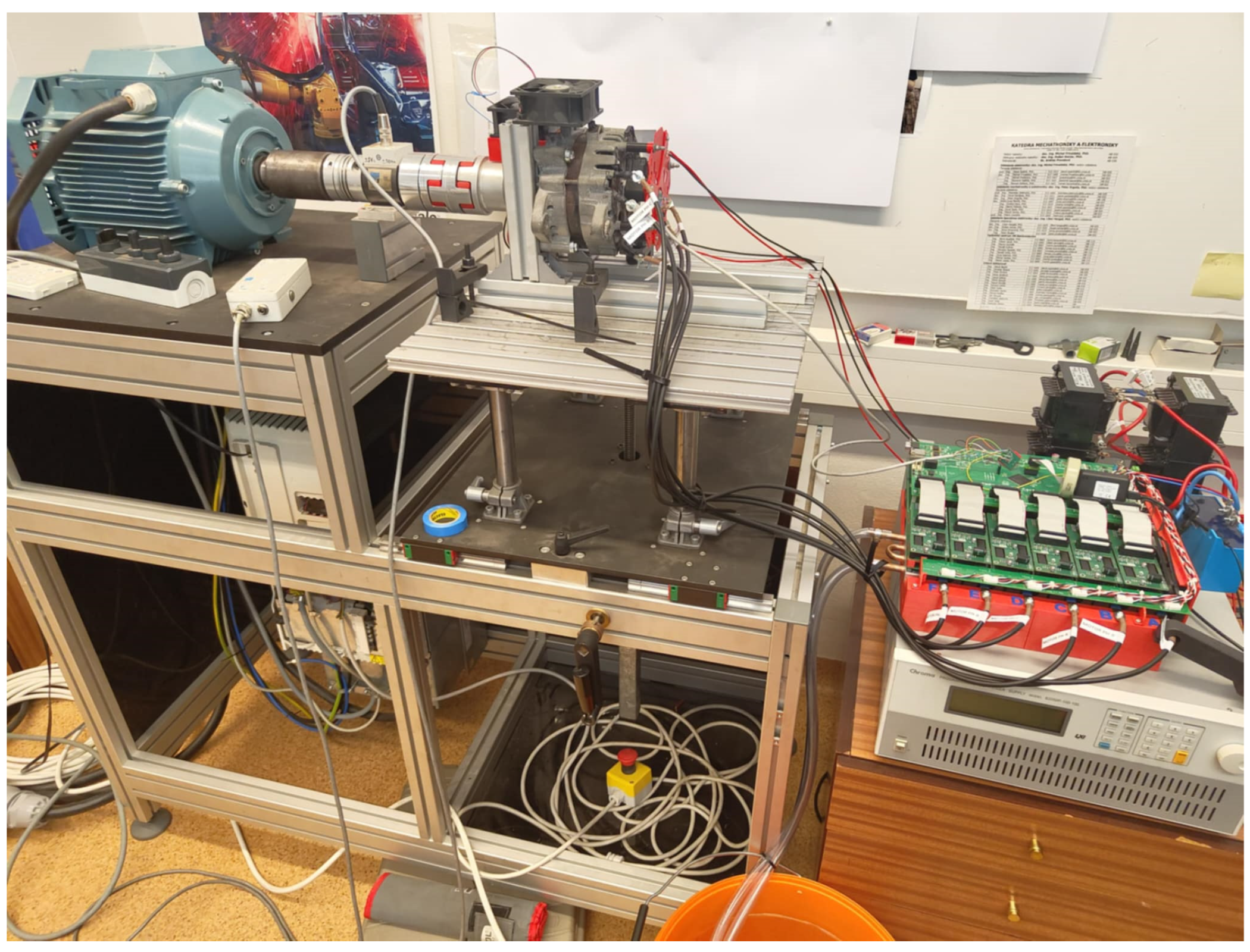
Due to the excessive heat produced when conducting high currents, the water cooling must be connected to the inverter. For the proper EESM testing, the load must be connected to the EESM shaft. For this purpose, a dynamometer with an output power of 7500 W was used. The dynamometer is capable of loading EESM with constant torque, which is suitable for our testing. The test setup is shown in Figure 17.
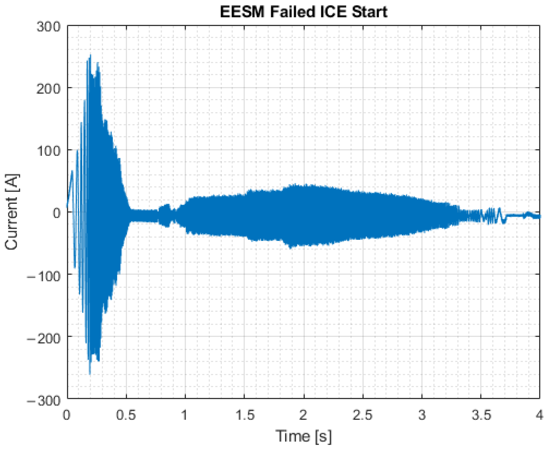
For the proper testing of the EESM in motor operation, the measurement of the behavior of the EESM on a real car must be conducted. For this, another car with the same EESM was measured during the ICE’s start procedure. Current waveforms of the EESM were measured from which the current and RPM of the SG can be determined. The waveform from the measurement is shown in Figure 18. During this test, the injectors were disconnected, allowing us to observe the behavior of the EESM when it is unable to start the engine properly.
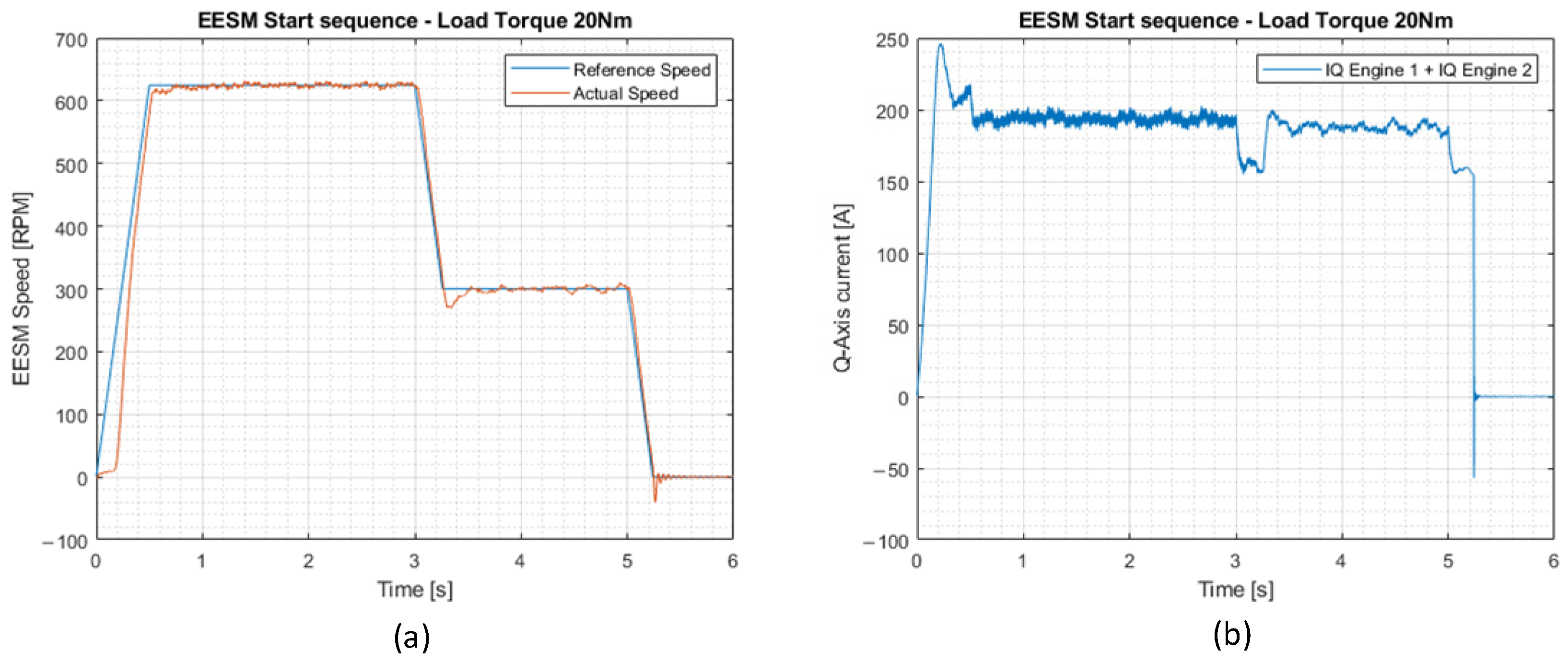
As shown in Figure 18, from 0 to 0.5 s, the current is very high because EESM must overcome the static resistance of the engine. The measured static torque of the engine is approximately 37 Nm. The SG is connected to the engine via a V-belt, utilizing pulleys. Total gear ratio ICE: SG is 1:2.5. At the beginning of the start, the SG has approximately 625 RPM (ICE has 250). After some time, when the engine is not starting, the RPM of the SG drops approximately to half (from 300 RPM at 1 s to 3 s) due to the excessive load on the SG. If the start is not successful, the SG shuts down after 3.5 s of operation. During EESM testing with our inverter, we attempted to replicate this behavior to verify that our designed control algorithm is correct. The static torque on the dynamometer was set to 20 Nm. EESM is directly connected to the dynamometer. Thus, if we set the speed to 625 RPM, the EESM has similar conditions to those in a practical application due to the gear ratio. If the EESM were connected to the motor through a V-belt, the resulting ICE speed would be 250 RPM, and the produced torque would be 50 Nm. The inverter is supplied from a single-quadrant 5.5 kW Chroma power supply. The control algorithm was programmed to spin up EESM to 625 RPM, hold this speed for 3 s, then lower the speed to 300 RPM, and then shut down. The result from measuring is shown in Figure 19.
Figure 19 shows the measured parameters of the test. In the left image, speed is shown, where the blue waveform represents the reference speed and the red waveform represents the actual speed measured by the TMAG6180. The speed reaches 90% of the requested speed within 480 ms at a static load of 20 Nm. The regulators were set to prevent overshoot at the start. The steady-state error in speed is −0.24%, where the requested speed is 625 RPM and the actual speed, as measured by the sensor, is 623.5 RPM. The efficiency of the inverter was not elaborated in this experiment, because this inverter will not be used in the final application.
Figure 19b shows Q-Axis currents of a six-phase motor. The waveform is the sum of the currents for both motors. As can be seen, the initial peak jumps to approximately 246 A during start-up (123 A per motor). Steady state current is held at approximately 194 A during the 625 RPM request and approximately 187 A during the 300 RPM request. There are no significant overshoots or undershoots. Turn-off undershoot (t = 5.1 s) is caused by the dynamometer itself.
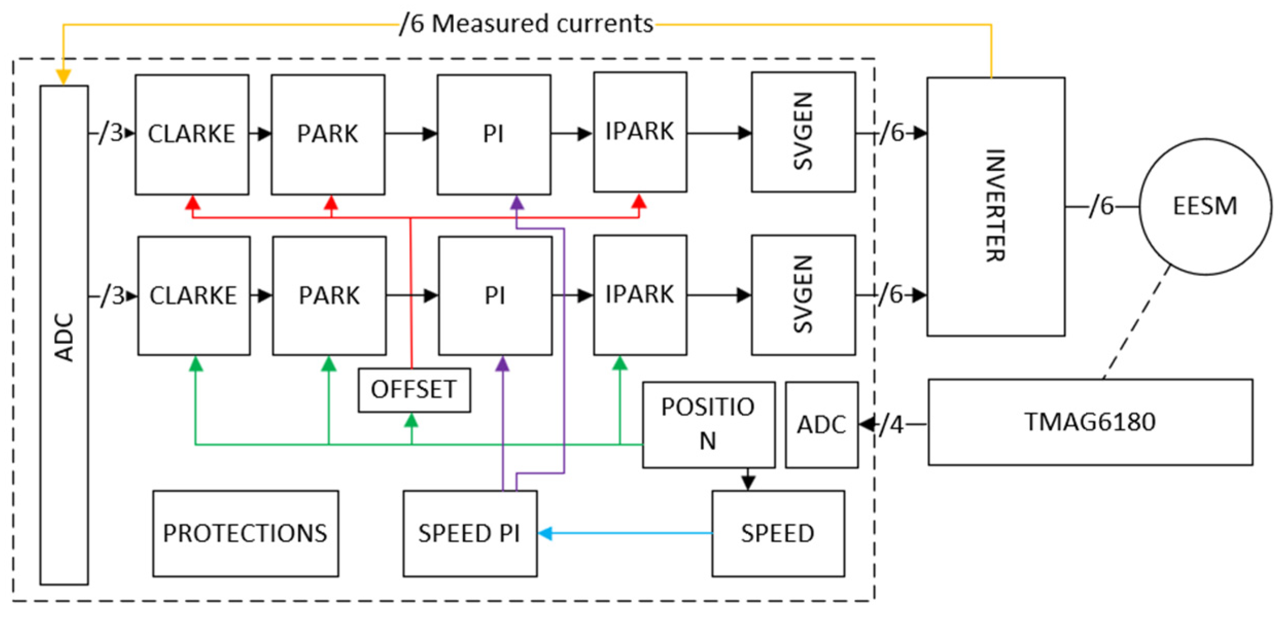
Because the evaluated EESM is a 6-phase machine with independent windings (each 3-phase machine has its own star point), a dual FOC algorithm was programmed, as shown in Figure 20. In short, every 3-phase machine is controlled separately by its own FOC algorithm. As a result, the 6-Phase EESM produces torque as a sum of individual torques from both machines. The sensor is aligned along the D axis of Engine 1, and an offset of 30° is added to the control algorithm for Engine 2, as only one sensor is used.
One core is executing the control algorithm for both machines. Together, 10 ADC values are measured, and the switching frequency of the inverter is set to 10 kHz. The current control loop execution period is 100 µs, and speed control loop execution is set to 1 ms. Protection block monitors the inverter status and reacts if one of the following events occurs:
-
Undervoltage protection: If the voltage on the DC bus drops significantly, the TRIP event is triggered, and all ePWMs are turned off to protect the power transistors.
-
Overtemperature protection: If the measured temperature of the power modules exceeds 60 °C, the inverter is turned off to prevent transistor destruction.
-
Overspeed protection: If the speed of the motor exceeds the set threshold, the inverter is disabled. This protection will safeguard the engine in the event of dynamometer failure or sudden torque drop, preventing RPM from reaching dangerous values.
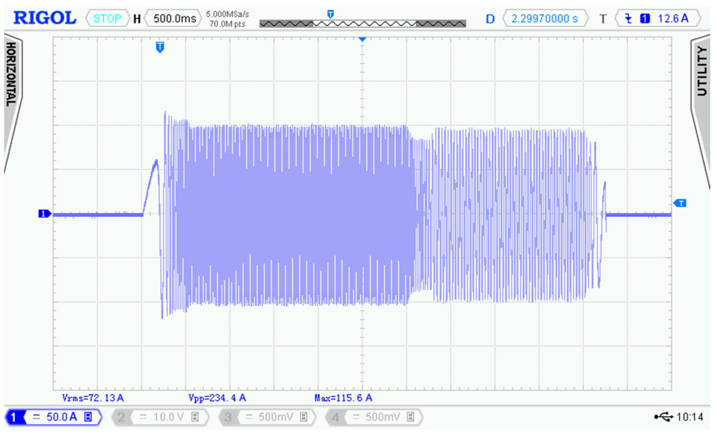
Because the used inverter is not ready for excitation winding, the excitation current was supplied from a second power supply and was held constant during the measurements. The excitation current was set to 4 A. The new control PCB features an excitation circuit that can be dynamically adjusted during EESG operation. The current waveform of Phase A of the EESM is shown in Figure 21.
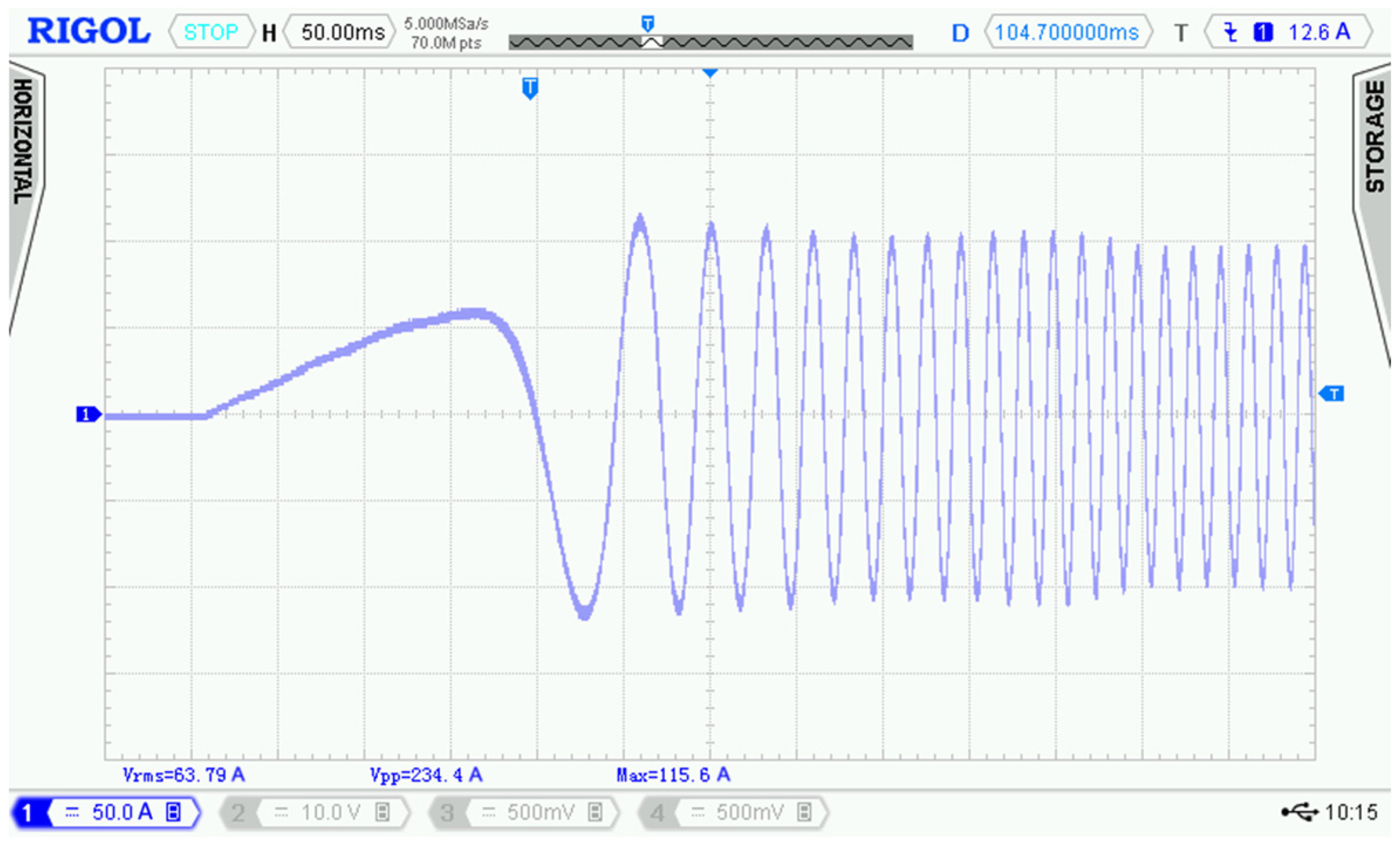
The primary difference between the measured waveform in the car and the simulated one is that the dynamometer continuously loads the EESM. In a real application, when the motor is spinning, the torque is lower, resulting in lower current. The target of this test was not to perfectly emulate the car’s measured waveform, but to verify that our designed control algorithm can handle the start of the SG without issues. The peak-peak current of the waveform is 234 A, and the RMS current is 72 A. Figure 22 shows a detail of the start of the SG.
As shown in Figure 21 and Figure 22, the speed regulator is set to achieve a nominal speed of 625 RPM in less than 500 ms, matching the performance of the measured EESM in the car. The starting current reaches 115 A, which already limits the usage of this modified TNPC inverter for further testing due to the current sensors’ limitations. The inverter was not designed to handle such high currents; thus, the following tests will be performed on the designed control board.
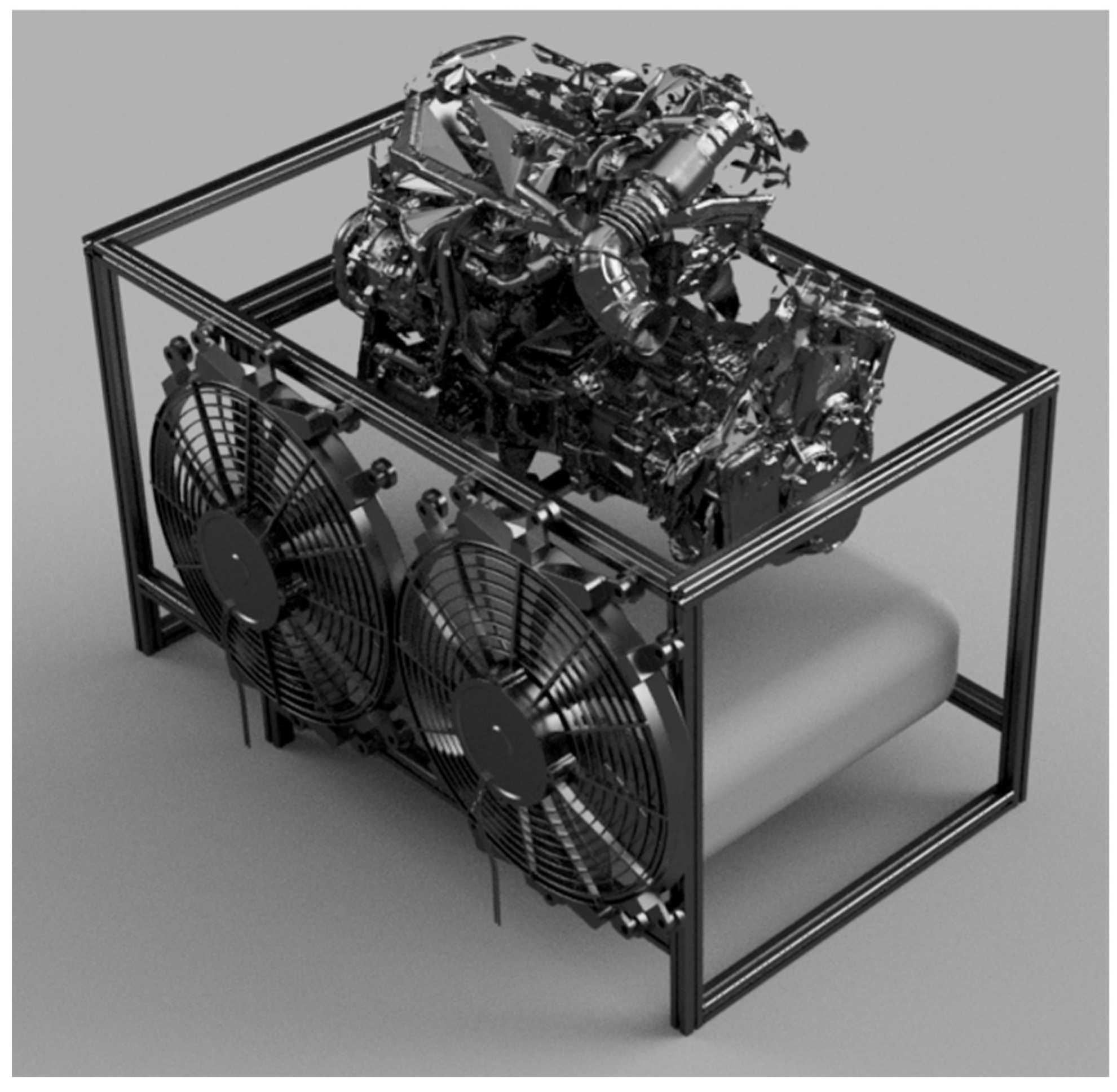
This designed control board, together with EESM, will be part of the teaching model for demonstrating a hybrid vehicle system. This system will consist of a functional ICE with SG mounted, a 48 V on-board battery, and an induction motor for loading the ICE to simulate drive profiles. The 3D designed model of the stand with motor and gas tank mounted is shown in Figure 23.
In this model, the operation of a mild hybrid engine can be demonstrated to students, and students can also develop their control algorithms for a proper EESM drive.

5. Conclusions

This paper demonstrates the potential to transform an automotive Electrically Excited Synchronous Machine (EESM) into an experimental and research environment by replacing its proprietary original control unit with a custom-designed controller. The EESM was an enclosed solution, but no documentation was provided, and direct reuse was not possible. By dismantling the drive and communicating directly with the power stage, we circumvented these limitations, achieving complete control over the rotor excitation and stator currents. The introduction of a six-phase EESM based on dual three-phase stator windings complicated the control approach but also delivered substantive benefits, including improved fault tolerance, reduced torque ripple, and improved thermal distribution. These characteristics make six-phase machines highly attractive for advanced instructional purposes and experimental validation of state-of-the-art control methods. The practical part of the control algorithm verification shows excellent results and a close approximation to the measured starting waveform of the car. The qualitative parameters exhibit no overshoots and swift regulation times, which are crucial for smooth EESM operation in conjunction with ICE. The provided platform can be utilized as a flexible testbed to test and develop excitation control strategies, available current control approaches, and fault-tolerant drive techniques. Augmenting the system with theoretical modeling, dynamic performance analysis, and field-weakening control techniques will be the focus of future studies to further enhance its position as a comprehensive research and teaching device.

6. Future Work

Although the control concept for the Electrically Excited Synchronous Machine (EESM) has been successfully validated on a different inverter platform using the same C2000 microcontroller, the custom-designed control board is still in production and has not yet undergone physical testing. The next significant step will involve assembling and validating the final hardware with the actual EESM unit. The long-term goal is to establish a reliable, open-source educational platform that demonstrates not only basic motor operation but also advanced control strategies suitable for modern automotive and industrial applications.

Author Contributions

Conceptualization, P.R. and M.D.; methodology, P.R.; software, P.R.; validation, P.R., M.P. and M.D.; formal analysis, M.D.; investigation, M.D.; resources, M.P.; data curation, P.R.; writing—original draft preparation, P.R.; writing—review and editing, P.R., M.P. and M.D.; visualization, M.P.; supervision, P.R.; project administration, M.D.; funding acquisition, P.R. All authors have read and agreed to the published version of the manuscript.

Funding

This research was funded by the EU NextGenerationEU through the Recovery and Resilience Plan for Slovakia under the project No. 09I03-03-V05-00002.

Acknowledgments

This article was supported by infrastructure from project 09I03-03-V06-00117.

Conflicts of Interest

The authors declare no conflicts of interest.

References

  1. Reddy, M.P.; Aneesh, A.; Praneetha, K.; Vijay, S. Global Warming Analysis and Prediction Using Data Science. In Proceedings of the Fifth International Conference on I-SMAC (IoT in Social, Mobile, Analytics and Cloud) (I-SMAC), Palladam, India, 11–13 November 2021; pp. 1055–1059. [Google Scholar] [CrossRef]
  2. Abu-Rub, H.; Malinowski, M.; Al-Haddad, K. Energy, Global Warming and Impact of Power Electronics in the Present Century. In Power Electronics for Renewable Energy Systems, Transportation and Industrial Applications; John Wiley & Sons: Hoboken, NJ, USA, 2014; pp. 1–26. [Google Scholar] [CrossRef]
  3. The Intergovernmental Panel on Climate Change (IPCC). Global Warming of 1.5 °C. Available online: https://www.ipcc.ch/sr15 (accessed on 23 July 2025).
  4. Zhai, Q.; Cao, H.; Zhao, X.; Yuan, C. Reducing Greenhouse Gas emissions of global automotive manufacturing through clean energy supply: Cost benefit analysis. In Proceedings of the 2011 IEEE International Symposium on Sustainable Systems and Technology, Chicago, IL, USA, 16–18 May 2011; p. 1. [Google Scholar] [CrossRef]
  5. DeCicco, J. Factor Analysis of Greenhouse Gas Emissions from Automobiles. 26 December 2012. Available online: https://papers.ssrn.com/sol3/papers.cfm?abstract_id=2205144 (accessed on 23 July 2025).
  6. Zaid, S.A.; Albalawi, H.; Alatwi, A.M.; Elemary, A. Performance Improvement of an Electric Vehicle Charging Station Using Brain Emotional Learning-Based Intelligent Control. Processes 2024, 12, 1014. [Google Scholar] [CrossRef]
  7. Valeo. 48 Volts Mild Hybrid System, the Affordable Electrification. Available online: https://www.valeo.com/en/48-volts-affordable-electrification/ (accessed on 23 July 2025).
  8. Liu, J.; Peng, H. Modeling and Control of a Power-Split Hybrid Vehicle. Control Systems Technology. IEEE Trans. Ind. Appl. 2008, 16, 1242–1251. [Google Scholar] [CrossRef]
  9. Audi Media Center. Drive System. Available online: https://www.audi-mediacenter.com/en/audi-technology-lexicon-7180/drive-system-7227 (accessed on 23 July 2025).
  10. Ruzimov, S.; Mavlonov, J.; Mukhitdinov, A. Analysis of the Powertrain Component Size of Electrified Vehicles Commercially Available on the Market. Commun. Sci. Lett. Univ. Zilina 2022, 24, B74–B86. [Google Scholar] [CrossRef]
  11. Pielecha, I.; Cieslik, W.; Szwajca, F. Energy Flow and Electric Drive Mode Efficiency Evaluation of Different Generations of Hybrid Vehicles under Di-versified Urban Traffic Conditions. Energies 2023, 16, 794. [Google Scholar] [CrossRef]
  12. Electronic Specifier. What Is a Belt or Integrated Starter Generator? Available online: https://www.electronicspecifier.com/industries/automotive/what-is-a-belt-or-integrated-starter-generator (accessed on 23 July 2025).
  13. Pels, T.; Reitz, D.; Lázló; Vestgård, B.; DevoTek, K. Small starter generator—Big Impact. In Proceedings of the 7th LuK Symposium, Bühl, Germany, 11–12 April 2002. [Google Scholar]
  14. Viorel, I.A.; Szabo, L.; Löwenstein, L.; Stet, C. Integrated Starter-Generators for Automotive Applications. Acta Electroteh. 2004, 45, 255–260. [Google Scholar]
  15. Stuffer, A.; Heinrich, D.; Hauck, C.; Schmidt, T.; Stief, H. Introduction of 48 V Belt Drive System: New tensioner and decoupler solutions for belt driven mild hybrid systems. In Proceedings of the 10th Schaeffler Symposium, Baden-Baden, Germany, 3–4 April 2014. [Google Scholar]
  16. Jacques, D.; Allegro MicroSystems. Common Driver Platform for 12 V and 48 V Systems. Available online: https://www.allegromicro.com/en/insights-and-innovations/technical-documents/12v-48v-bsg (accessed on 23 July 2025).
  17. Valeo Technical Bulletin, iBSG—Starter Alternator, TSB-VES-202301-1181-VSIN-en. February 2023. Available online: https://api.techassist.valeoservice.systems/sites/default/files/technical-document/assets/TSB-VES-202301-1181-VSIN-en.pdf (accessed on 23 July 2025).
  18. Nøland, J.K.; Nuzzo, S.; Tessarolo, A.; Alves, E.F. Excitation System Technologies for Wound-Field Synchronous Machines: Survey of Solutions and Evolving Trends. IEEE Access 2019, 7, 109699–109718. [Google Scholar] [CrossRef]
  19. James; Widmer, D.; Martin, R.; Kimiabeigi, M. Electric vehicle traction motors without rare earth magnets. Sustain. Mater. Technol. 2015, 3, 7–13. [Google Scholar] [CrossRef]
  20. Graffeo, F.; Vaschetto, S.; Cossale, M.; Kerschbaumer, M.; Bortoni, E.C.; Cavagnino, A. Cylindrical Wound-Rotor Synchronous Machines for Traction Applications. In Proceedings of the International Conference on Electrical Machines (ICEM), Gothenburg, Sweden, 23–26 August 2020; pp. 1736–1742. [Google Scholar] [CrossRef]
  21. Tang, J.; Liu, Y.; Sharma, N. Modeling and Experimental Verification of High-Frequency Inductive Brushless Exciter for Electrically Excited Synchronous Machines. IEEE Trans. Ind. Appl. 2019, 55, 4613–4623. [Google Scholar] [CrossRef]
  22. Graffeo, F.; Stiscia, O.; Vaschetto, S.; Cavagnino, A.; Tenconi, A. Doubly Excitated Synchronous Machines for Traction Applications. In Proceedings of the IEEE 30th International Symposium on Industrial Electronics (ISIE), Kyoto, Japan, 20–23 June 2021; pp. 1–8. [Google Scholar] [CrossRef]
  23. Müller, S.; Maier, D.; Parspour, N. Inductive Electrically Excited Synchronous Machine for Electrical Vehicles—Design, Optimization and Measurement. Energies 2023, 16, 1657. [Google Scholar] [CrossRef]
  24. Rubino, S.; Bojoi, R.; Cavagnino, A.; Vaschetto, S. Asymmetrical twelve-phase in-duction starter/generator for more electric engine in aircraft. In Proceedings of the IEEE Energy Conversion Congress and Exposition (ECCE), Milwaukee, WI, USA, 18–22 September 2016; pp. 1–8. [Google Scholar] [CrossRef]
  25. Long, Q.; Zhou, Z.; Lin, X.; Liao, J. Investigation of a novel brushless electrically excited synchronous machine with arc-shaped rotor structure. Energy Rep. 2020, 6 (Suppl. 9), 608–617. [Google Scholar] [CrossRef]
  26. Valeo Service. 48 V Mild Hybrid Systems. Available online: https://www.valeoservice.com/en-com/48v-mild-hybrid-systems (accessed on 23 July 2025).
  27. Choi, K.-S. Method of Controlling Energy Regeneration for Mild Hybrid Vehicle. US Patent Number US10787163B2, 29 September 2020. [Google Scholar]
  28. Kellner, J.; Kaščák, S.; Praženica, M.; Resutík, P.; Ferková, Ž. Implementation of New Fault Tolerant Control for Five-Phase Induction Motor in Fault Operation. In Proceedings of the 2022 ELEKTRO, Krakow, Poland, 23–26 May 2022; pp. 1–6. [Google Scholar] [CrossRef]
  29. Kumar, A.S.A.; George, B.; Mukhopadhyay, S.C. Technologies and Applications of Angle Sensors: A Review. IEEE Sens. 2021, 21, 7195–7206. [Google Scholar] [CrossRef]
  30. Wang, S.; Ma, R.; Cao, F.; Luo, L.; Li, X. A Review: High-Precision Angle Measurement Technologies. Sensors 2024, 24, 1755. [Google Scholar] [CrossRef] [PubMed]
  31. Texas Instruments. TMAG6180-Q1 Automotive High-Precision Analog AMR 360° Angle Sensor Datasheet; Revised March 2024; Texas Instruments: Dallas, TX, USA, 2024; Available online: https://www.ti.com/lit/ds/symlink/tmag6180-q1.pdf?ts=1755612449953 (accessed on 23 July 2025).
  32. Resutík, P.; Praženica, M.; Kaščák, S. Design and Verification of Multiphase Multilevel Traction Inverter. Appl. Sci. 2024, 14, 10562. [Google Scholar] [CrossRef]
  33. Allegro Microsystems Application Information AN296245, Material Selection and Geometry Considerations for High Current Sensing Magnetic Flux Concentrator Designs. Available online: https://www.allegromicro.com/-/media/files/application-notes/an296245-high-current-sensing-flux-concentrator-design.pdf?sc_lang=en (accessed on 23 July 2025).
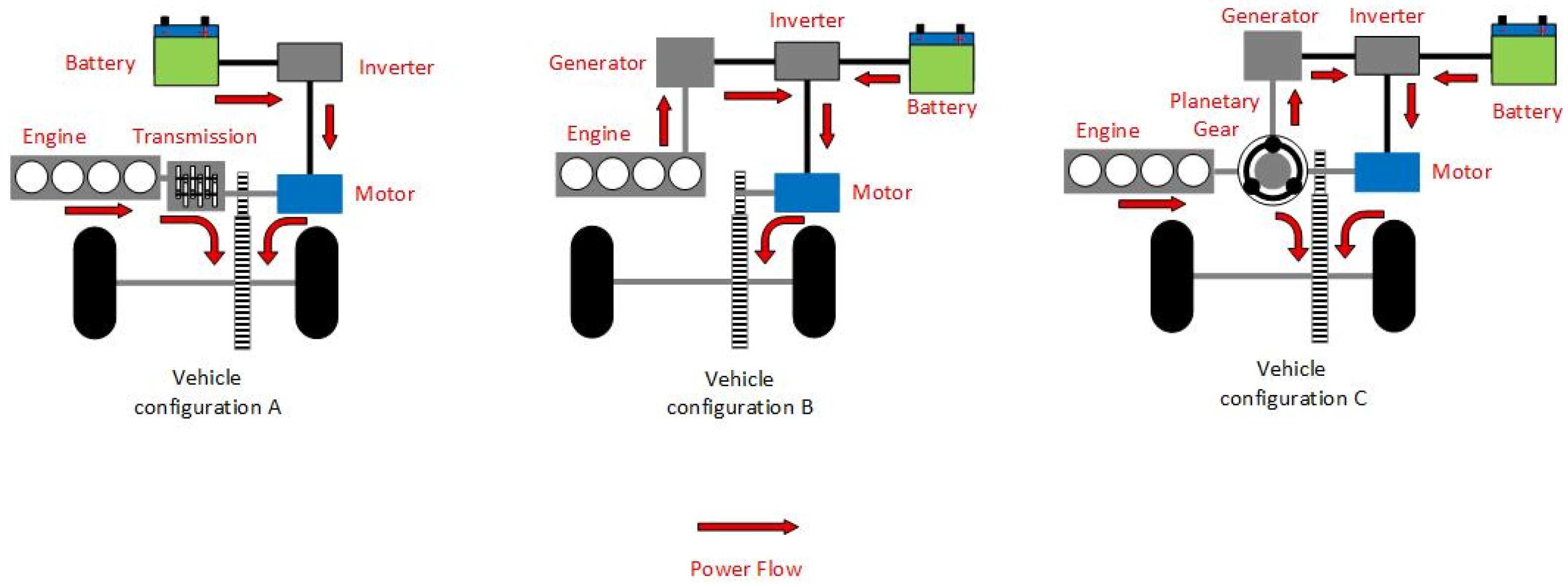
Figure 1. Types of hybrid electric vehicle configurations. Configuration A—Serial, Configuration B—Parallel, Configuration C—Series-Parallel.
Wevj 16 00480 g001
Figure 2. Placement of the electric motor in a parallel hybrid [10].
Wevj 16 00480 g002
Figure 3. Physical attachment of the SG to the ICE with the belt tensioner.
Wevj 16 00480 g003
Figure 4. SG mounted on the ICE using the belt.
Wevj 16 00480 g004
Figure 5. Original control board before disassembly.
Wevj 16 00480 g005
Figure 6. 6-phase engine (2 × 3-phase, with 30° shift).
Wevj 16 00480 g006
Figure 7. Physical resolver coil arrangement.
Wevj 16 00480 g007
Figure 8. AMR Sensor magnet position for position sensing.
Wevj 16 00480 g008
Figure 9. Magnet and sensor mounting on the EESM: (Left Image) Front view, (Right Image) Side view.
Wevj 16 00480 g009
Figure 10. Existing inverter assembly.
Wevj 16 00480 g010
Figure 11. Designed the current measurement PCBs for two phases.
Wevj 16 00480 g011
Figure 12. Principal current measurement using a flux concentrator and a Hall-effect sensor.
Wevj 16 00480 g012
Figure 13. Block diagram of the newly designed EESM control board.
Wevj 16 00480 g013
Figure 14. Newly designed control board for EESM. (Left) Top View; (Right) Bottom View.
Wevj 16 00480 g014
Figure 15. 6-phase inverter.
Wevj 16 00480 g015
Figure 16. EESM Test setup using modified TNPC inverter.
Wevj 16 00480 g016
Figure 17. EESM is connected to the dynamometer and a 6-phase inverter.
Wevj 16 00480 g017
Figure 18. Measured EESM current during failed start in the KIA Sportage.
Wevj 16 00480 g018
Figure 19. Emulated start sequence (a) EESM Speed, (b) EESM Q-Axis Currents.
Wevj 16 00480 g019
Figure 20. Simplified dual FOC of 6-phase EESM.
Wevj 16 00480 g020
Figure 21. Phase current during the engine start.
Wevj 16 00480 g021
Figure 22. Details of the EESM start from 0 RPM to 625 RPM.
Wevj 16 00480 g022
Figure 23. Three-dimensional model of the teaching stand.
Wevj 16 00480 g023
Table 1. Parallel hybrid car types and features.
PositionP0P1P2P3P4/P5
e-machine typeBSGISGBSG/ISGISGISG
Main functionsStart-Stop and Energy RecoveryStart-Stop and Energy RecoveryEnhanced
Start-Stop,
Improved Energy Recovery and Electric Drive
Enhanced
Start-Stop,
Improved Energy Recovery and Electric Drive
Enhanced
Start-Stop,
Improved Energy Recovery and Electric Drive
Powertrain
connection
Engine via
toothed belt
Engine to
Crankshaft
Transmission Input–either side connected Toothed Belt or
built-in Gear Mesh
Transmission
output via Gear Mesh
Rear Axle or
Differential via
Gear Mesh
Ability to disconnect
from ICE
NoNoYesYesYes
Integration CostLowMediumHighHighHigh
Braking energy recoveryGoodBetterBestBestBest
Energy recovery with engine offNoNoYesYesYes
Electric drive capabilityNoNoYesYesYes
Electric boost capabilityYesYesYesYesYes
Disclaimer/Publisher’s Note: The statements, opinions and data contained in all publications are solely those of the individual author(s) and contributor(s) and not of MDPI and/or the editor(s). MDPI and/or the editor(s) disclaim responsibility for any injury to people or property resulting from any ideas, methods, instructions or products referred to in the content.