Article

Energy-Efficient Battery Thermal Management in Electric Vehicles Using Artificial-Neural-Network-Based Model Predictive Control

School of Mechanical Engineering, Pusan National University, Busan 46241, Republic of Korea
*
Author to whom correspondence should be addressed.
World Electr. Veh. J. 2025, 16(5), 279; https://doi.org/10.3390/wevj16050279
Submission received: 27 February 2025 / Revised: 14 May 2025 / Accepted: 15 May 2025 / Published: 17 May 2025

Abstract

This study presents a Model Predictive Control (MPC) strategy for the Battery Thermal Management System (BTMS) in electric vehicles (EVs) to optimize energy efficiency while maintaining battery temperature within the optimal range. Due to the complexity of BTMS dynamics, a high-fidelity model was developed using MATLAB/Simscape (2021a), and an artificial neural network (ANN)-based model was designed to achieve high accuracy with reduced computational load. To mitigate oscillatory control inputs observed in conventional MPC, an infinity-horizon MPC framework was introduced, incorporating a value function that accounts for system behavior beyond the prediction horizon. The proposed controller was evaluated using a simulation environment against a conventional rule-based controller under varying ambient temperatures. Results demonstrated significant energy savings, including a 78.9% reduction in low-temperature conditions, a 36% reduction in moderate temperatures, and a 27.8% reduction in high-temperature environments. Additionally, the controller effectively stabilized actuator operation, improving system longevity. These findings highlight the potential of ANN-assisted MPC for enhancing BTMS performance while minimizing energy consumption in EVs.

1. Introduction

The growing electrification of vehicles and the tightening of environmental regulations have significantly increased interest in electric vehicles (EVs) [1,2]. However, concerns regarding driving range limitations and safety remain major challenges. Both issues are closely linked to the thermal management of electric and electronic components, particularly the battery. Lithium-ion batteries, widely used in EVs, operate optimally within a temperature range of 15 °C to 35 °C. Operating a battery outside of its optimal temperature range can significantly affect its performance and safety. At low temperatures, increased internal resistance and lithium plating on the anode can degrade performance. At high temperatures, accelerated electrochemical reactions at both electrodes compromise stability and reduce battery life. Moreover, excessive heat can lead to critical safety risks, such as thermal runaway or explosion [3,4,5,6,7]. In particular, thermal runaway in lithium-ion batteries typically begins near 65 °C with the decomposition of the SEI, making battery thermal management essential. Consequently, extensive studies have been conducted to enable efficient battery cooling within the battery pack to prevent thermal runaway. Various approaches have been proposed, including the integration of PCM with micro-channel plate cooling systems, hybrid PCM–metal foam and immersion cooling technologies, and the use of nanofluids with superior thermal conductivity [8,9,10,11].
To maintain battery temperature within the optimal range, EVs are equipped with Battery Thermal Management Systems (BTMSs). Various BTMS configurations have been developed, with the most common being air cooling, liquid cooling, and phase change material (PCM)-based systems.
Air cooling systems utilize ambient air to directly cool the battery modules. This method offers a simple structure and low cost; however, it suffers from low heat transfer efficiency and limited performance under high ambient temperatures. Liquid cooling systems, on the other hand, use a circulating coolant to absorb heat from the battery and release it through a radiator. While this method provides significantly improved thermal performance compared to air cooling, it comes with increased system complexity and higher implementation costs [12,13].
PCM-based thermal management has emerged as an alternative approach and is typically classified into two main types: direct and secondary loop systems. In the direct method, the PCM is in direct contact with the battery cells, offering the highest cooling performance due to efficient heat absorption during phase transition. However, this configuration is sensitive to PCM leakage, which poses reliability concerns [14].
The secondary loop approach addresses this issue by thermally decoupling the PCM from the battery. In this configuration, the PCM regulates the temperature of a coolant loop, which then indirectly cools the battery pack. Although the thermal efficiency is somewhat reduced and the system becomes more complex, this method eliminates the risk of PCM leakage and enables greater flexibility in system design. Specifically, the coolant loop can be extended to cool additional components, such as electric motors and inverters, allowing for integrated thermal management [15].
Due to these advantages, recent electric vehicles have adopted the PCM-based secondary loop BTMS. Accordingly, this study focuses on a BTMS that employs a PCM-based secondary loop configuration as its core cooling strategy.
However, operating BTMS components, such as the refrigeration cycle and coolant loop, consumes significant energy. Studies indicate that heating and cooling operations in EVs can reduce driving range by up to 50% [16]. Therefore, an effective control strategy is essential to minimize energy consumption while ensuring battery temperature remains within the optimal range.
Existing BTMS control strategies primarily rely on rule-based controllers, proportional–integral–derivative (PID) controllers [17,18], and fuzzy logic controllers [19,20]. These control strategies offer the advantage of ease of implementation and minimal computational burden, as complex mathematical models are not required. However, incorporating system constraints and adapting to dynamic driving conditions and external disturbances are challenging, making it difficult to derive optimal control inputs and ensure minimal energy consumption [21,22]. To address this limitation, optimal control-based approaches, such as Model Predictive Control (MPC), have been explored [23,24,25]. MPC predicts the future states of a system using a mathematical model and determines future control inputs by optimizing a cost function to achieve control objectives. In the case of a BTMS, MPC can predict future battery heat generation and regulate battery temperature while improving energy efficiency by designing a cost function that considers both battery temperature and energy consumption. However, its effectiveness depends on the accuracy of the control model and the length of the prediction horizon. Due to computational constraints, many BTMS studies employ simplified models, often at the cost of reduced accuracy.
Another promising approach is Stochastic Dynamic Programming (SDP) [26], which determines optimal control inputs for stochastic systems. In BTMS applications, SDP predicts probabilistic future heat generation based on vehicle driving conditions and adjusts control inputs accordingly. However, similarly to MPC, SDP’s performance depends on the accuracy of state transition probabilities. Although detailed models provide higher accuracy, they inherently increase the number of system states. In conventional optimization problems, computational complexity tends to grow proportionally to the cube of the number of states, making real-time operation challenging [27].
This study proposes an MPC-based control strategy utilizing a BTMS model designed to balance accuracy and computational efficiency. BTMS involves complex phenomena, such as fluid flow, two-phase heat transfer, and heat exchange, making numerical models computationally demanding and unsuitable for real-time control. To overcome this challenge, an artificial neural network (ANN) is employed to develop a high-accuracy, computationally efficient, optimization-oriented model. Using this ANN-based control model, an MPC framework is designed to minimize BTMS energy consumption while maintaining battery temperature within the optimal range. Furthermore, this study introduces an infinity-horizon MPC to mitigate control input oscillations, a common issue in conventional MPC implementations.
The remainder of this paper is organized as follows. Section 2 presents the optimization-oriented model design. Section 3 details the controller design. Section 4 validates the proposed controller. Finally, Section 5 concludes the study.

2. BTMS Control Model
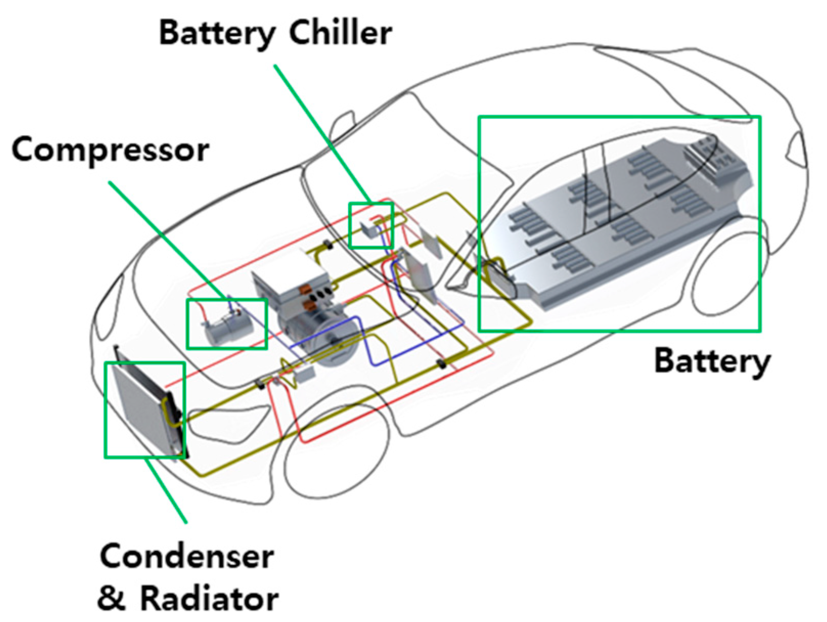
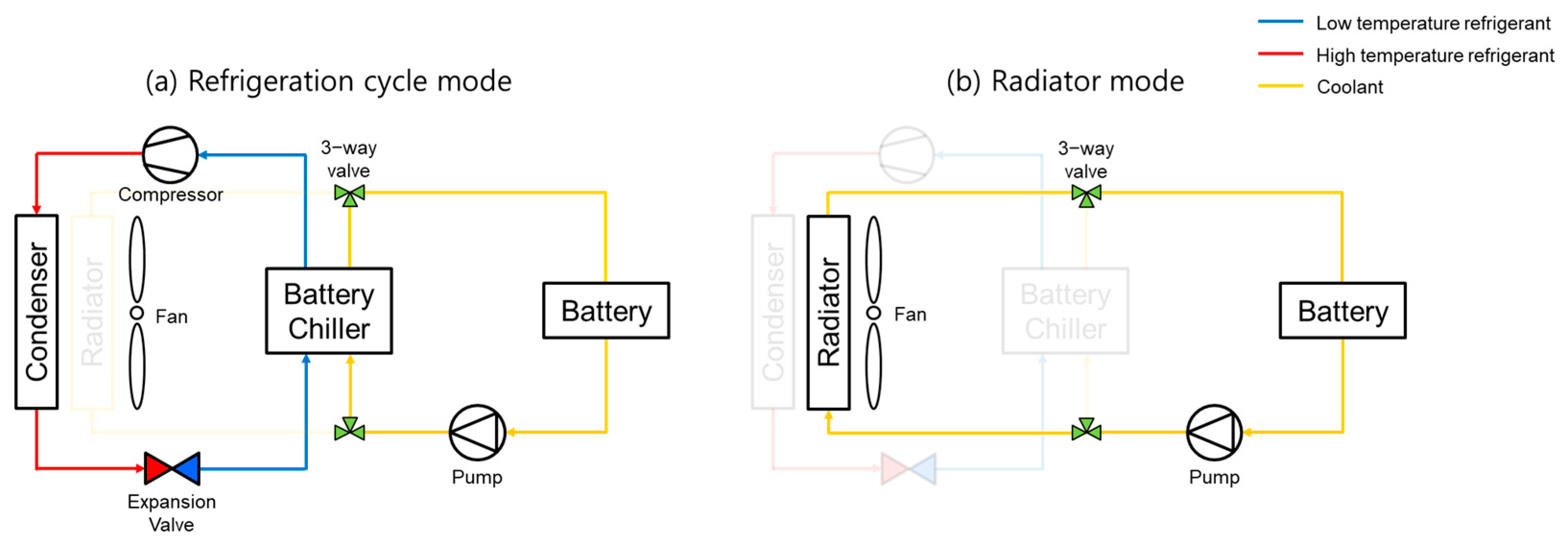
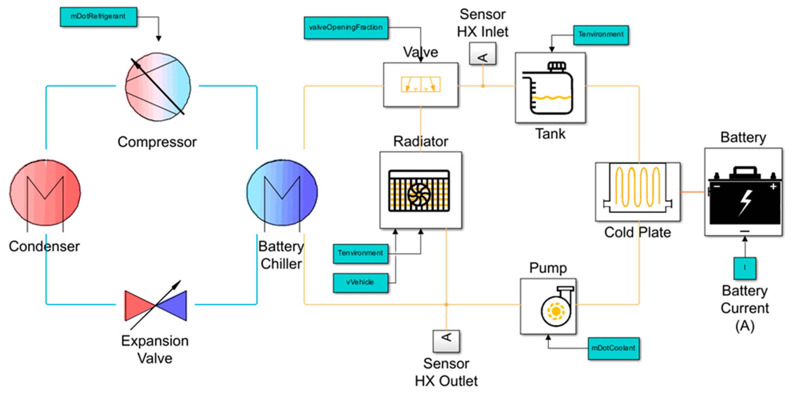
2.1. BTMS Operation

The BTMS in EVs consists of a coolant loop that regulates battery temperature and a refrigeration cycle that controls the coolant temperature, as illustrated in Figure 1. The system operates in two modes depending on how the coolant temperature is managed.
The first mode is the refrigeration cycle mode, shown schematically in Figure 2a. In this mode, the coolant temperature is reduced through heat exchange with a low-temperature refrigerant in the coolant chiller. This mode provides high cooling performance, making it suitable for scenarios where ambient temperatures are excessively high or the battery generates substantial heat. However, it requires significant energy consumption due to the operation of the refrigeration cycle. A previous study reported experimental results, with a significant driving range reduction up to 16.7% due to use of the refrigeration cycle for cooling [16].
The second mode is the radiator mode, depicted in Figure 2b. Here, the coolant temperature is controlled by ambient air through a radiator. While this mode offers lower cooling performance than the refrigeration cycle, it significantly reduces energy consumption.

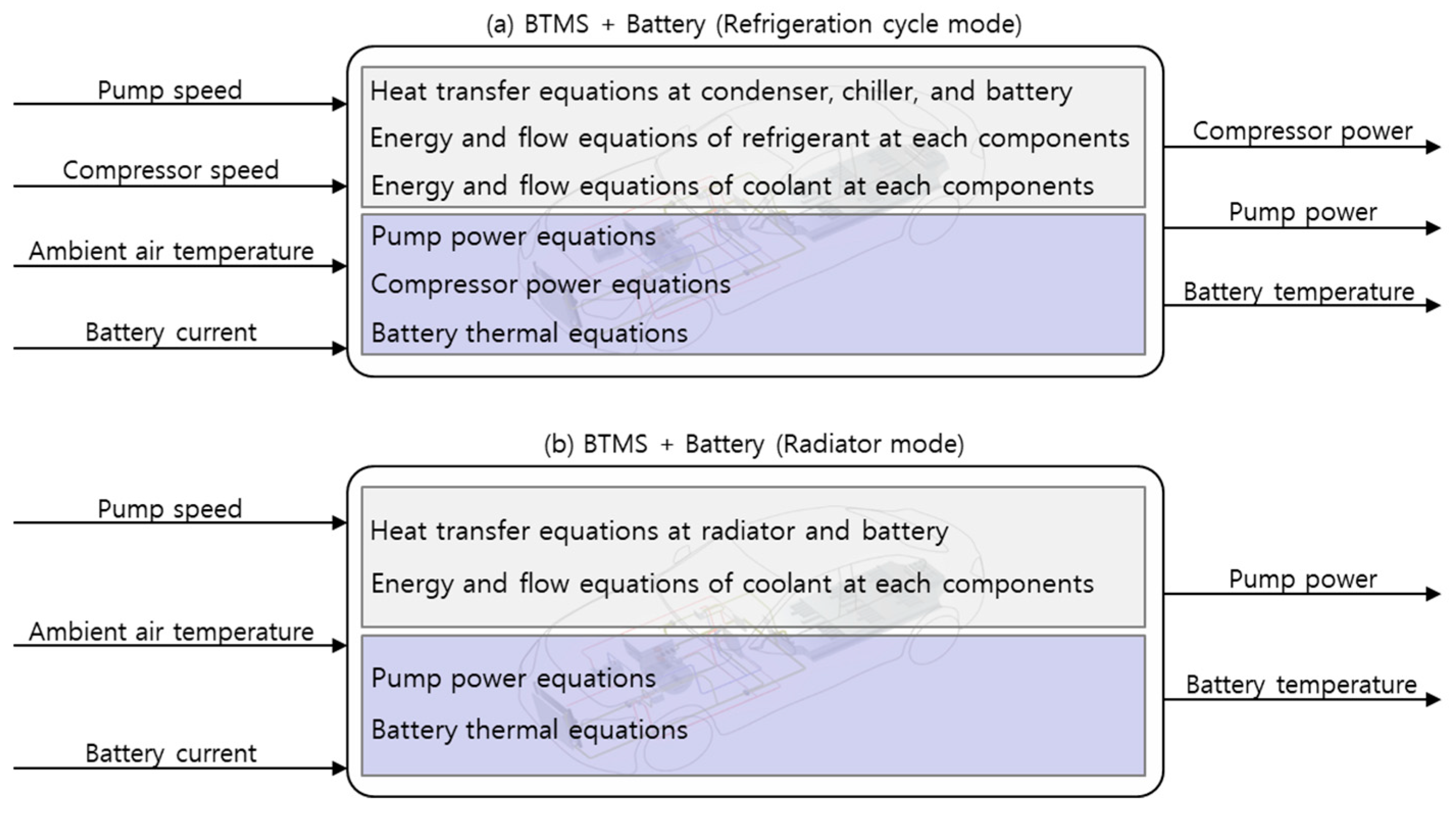
2.2. Model Structure

The BTMS is typically modeled by considering compressible and incompressible fluid flows, phase changes in two-phase fluids, and heat exchange processes within heat exchangers. Figure 3 presents the input/output signals and the internal computational functions associated with the BTMS control model. Notably, the gray-shaded regions in Figure 3a,b encapsulate the majority of the complex and nonlinear computational procedures inherent to the BTMS, as mentioned above. Obtaining numerical solutions within these regions requires iterative computations until convergence is achieved [28]. Moreover, due to the large number of parameters involved in this computation process, numerous assumptions are typically required, which can significantly compromise both the real-time performance and the overall accuracy of the control system.
To address these challenges, this study employs an artificial neural network (ANN)-based data-driven approach to model the BTMS. An ANN provides advantages, such as high-speed information processing, mapping capabilities, and fault tolerance [29,30,31]. To address this, the complex heat transfer and energy equations illustrated in the gray-shaded regions of Figure 3 were modeled using an ANN, as shown in the corresponding gray-shaded areas in Figure 4a,b. Additionally, other components, such as pump power, compressor power, and battery thermal dynamics, are modeled using mathematical equations with lookup tables, as shown in the light-blue-shaded region in Figure 4. To perform this calculation for the compressor, the compressor’s mass flow rate, isentropic efficiency, and power conversion efficiency are required. These parameters are provided in the form of lookup tables based on compressor speed, the pressure ratio, and torque, as illustrated in Figure 5. Similarly, for the pump, the coolant mass flow rate and mechanical power are given as functions of pump RPM, while the pump’s power conversion efficiency is represented as a function of pump RPM and torque, as shown in Figure 6.

2.3. Model for the Refrigeration Cycle with the Coolant Cycle

In refrigeration mode, an ANN is developed to approximate the refrigeration cycle’s characteristics, including heat exchange in the condenser, the battery chiller, and the battery, as shown in Figure 4a. The input signals of the ANN are the compressor speed, pump speed, battery temperature, and ambient temperature. The output signals of the ANN include the pressure and specific enthalpy at the compressor inlet/outlet and the temperature increase of the coolant passing through the battery. The ANN structure consists of two hidden layers with eight nodes each, using the ReLU activation function to balance computational efficiency and accuracy.

2.4. Model for the Coolant Cycle

In radiator mode, an ANN approximates heat exchange in the radiator and the battery, as indicated in Figure 4b. The input signals of the ANN are the battery temperature, ambient temperature, and pump speed. The output signal of the ANN is the coolant temperature increase at the battery inlet/outlet. The ANN structure mirrors that of the refrigeration cycle mode for consistency in computational efficiency and accuracy.

2.5. Battery Thermal Model

The battery thermal dynamics are expressed as follows:
T ˙ b a t t = Q ˙ b a t t , g e n Q ˙ c o o l m b a t t C b a t t
where T ˙ b a t t is the rate of battery temperature change, Q ˙ b a t t , g e n is the battery’s heat generation, Q ˙ c o o l is the cooling rate, mbatt is the battery’s thermal mass, and Cbatt is the battery’s specific heat capacity. The battery’s heat generation Q ˙ b a t t , g e n is given by
Q ˙ b a t t , g e n = I b a t t 2 R b a t t + I b a t t T b a t t d U o c v d T b a t t
where Ibatt is the battery’s current, Rbatt is the internal resistance of the battery, and Uocv is the open circuit voltage of the battery. The cooling rate Q ˙ c o o l is expressed as
Q ˙ c o o l = m ˙ c l n t C c l n t Δ T c l n t , b a t t ,
where m ˙ c l n t is the coolant mass flow rate, Cclnt is the coolant specific heat capacity, and ΔTclnt,batt represents the temperature increase of the coolant passing through the heated battery, which is one of the output signals from the ANN model in Figure 4a.

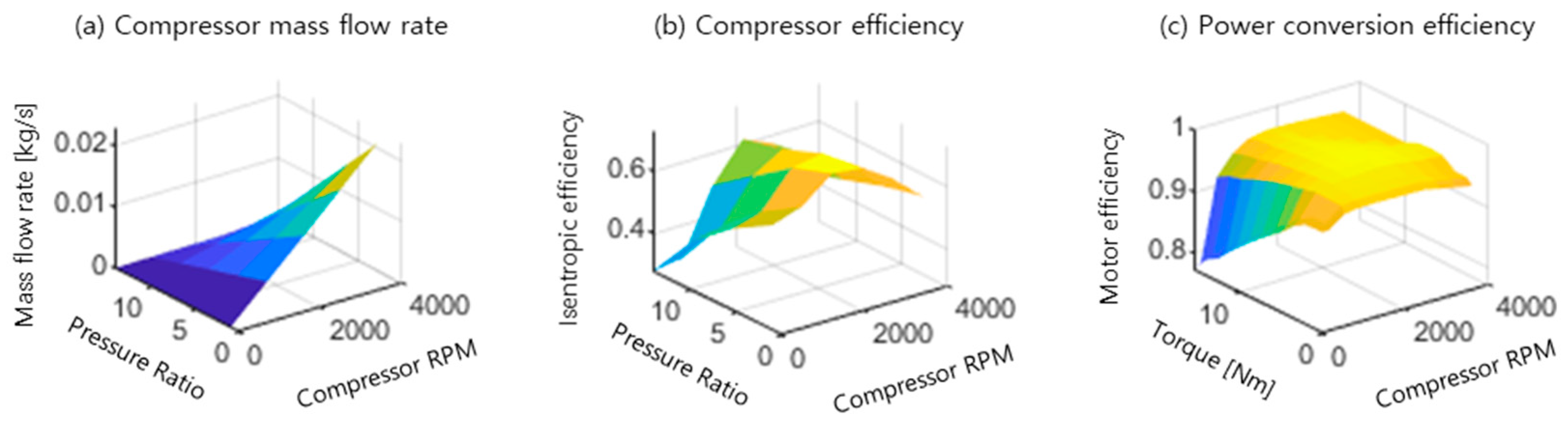
2.6. Compressor Power Model

The electric power consumption of the compressor, Pcomp, is given by
P c o m p = m ˙ r f g ( h c o m p , o u t h c o m p , i n ) η c o m p η m o t , c o m p ,
where hcomp,in and hcomp,out are the specific enthalpy values at the compressor inlet and outlet, respectively, which are also output signals of the ANN model in Figure 4a. m ˙ r f g is the refrigerant mass flow rate, determined as a function of the pressure ratio and the compressor speed (Figure 5a). The overall compressor efficiency ηcomp is the product of isentropic and volumetric efficiencies (Figure 5b), and ηmot,com is the power conversion efficiency of the compressor motor (Figure 5c).

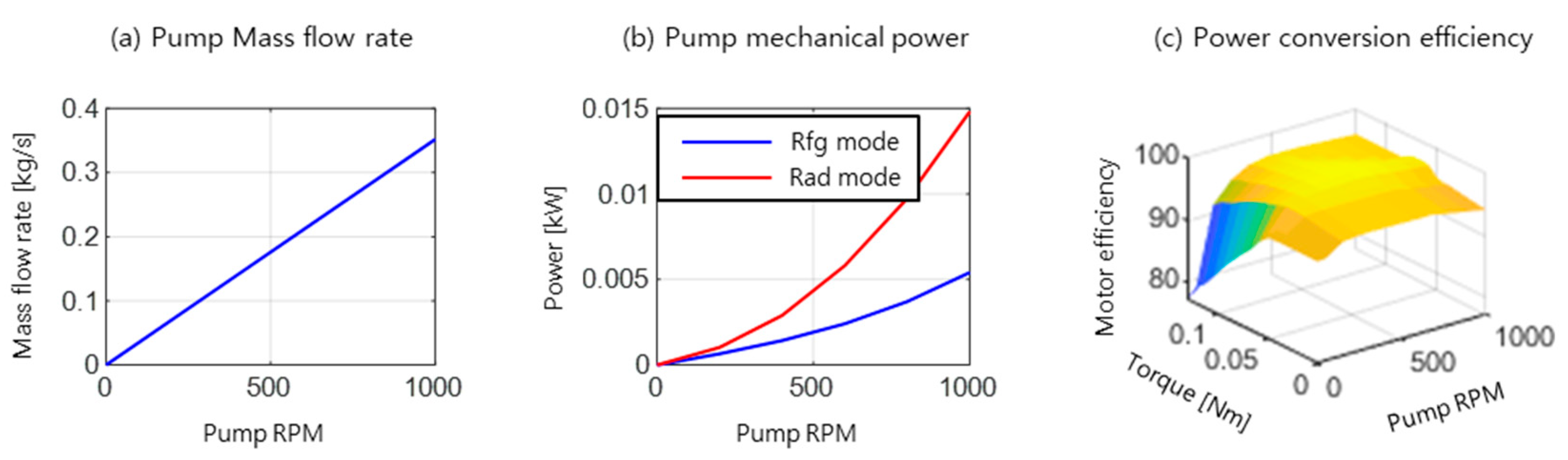
2.7. Pump Power Model

The electric power consumption of the pump, Ppump, is given by
P p u m p = P p u m p , m e c h η m o t , p u m p ,
where Ppump,mech represents the mechanical power of the pump, which is approximated as a function of the pump’s speed, as shown in Figure 6b. The pump motor’s efficiency, ηmot,pump, is shown in Figure 6c. Additionally, the coolant mass flow rate, m ˙ c l n t , used in Equation (3), is also dependent on pump speed, as illustrated in Figure 6a. The mechanical power varies across different operational modes due to variations in component configurations and fluid path lengths.

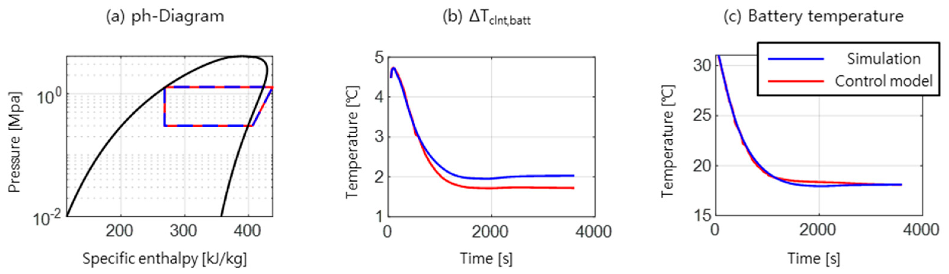
2.8. Model Training and Validation

A high-fidelity MATLAB/Simscape model (Figure 7) was developed for data collection using R-134a as the refrigerant and a 50–50 mixture of water and ethylene glycol as the coolant. Mode transitions were assumed to be ideally controlled by valves. Training data were generated from steady-state outputs by varying outdoor temperature, battery temperature, compressor speed, and pump speed.
Model validation involved comparing ANN-based model outputs with results from simulations. In refrigeration mode, validation was performed using a pressure–enthalpy diagram and by comparing coolant temperature differences at the battery inlet and outlet. Battery temperature predictions from the ANN-based model were also compared to MATLAB/Simscape results. In radiator mode, validation followed the same methodology.
Figure 8 and Figure 9 show validation results for both modes, where blue lines represent MATLAB/Simscape results and red lines denote ANN-based model results. In both modes, the battery temperatures predicted by the ANN model and those obtained from the MATLAB/Simscape simulations exhibited high accuracy, with RMSE values of 0.2150 for the refrigeration cycle mode and 0.0554 for radiator mode. Due to the greater complexity of the refrigeration cycle compared to the radiator cycle, the ANN model exhibited slightly higher prediction error in the former. Nevertheless, the accuracy achieved in both modes is sufficient for control applications. Moreover, the ANN-based models required only 0.004% of a single simulation step, confirming their suitability for model-based controller design in terms of accuracy and computational efficiency.

3. Controller Design

For MPC formulation, control model is expressed as
x ( k + 1 ) = f ( x ( k ) , u ( k ) , w ( k ) )
where x represents the state, u is the control input, and w denotes the system disturbance. The system states include battery temperature and the speeds of the pump and compressor from the previous time step. The control inputs consist of the mode change command and the time derivatives of the compressor and pump speeds. The disturbance is battery heat generation. The mathematical representations of the state, control input, and disturbance are as follows:
x ( k ) = T b a t t ( k ) ω c o m p ( k 1 ) ω p u m p ( k 1 ) , u ( k ) = m o d e ( k ) ω ˙ c o m p ( k ) ω ˙ p u m p ( k ) , w ( k ) = Q ˙ b a t t , g e n ( k ) .
The choice of time derivatives of compressor and pump speeds as control variables is motivated by the need to mitigate excessive speed fluctuations. By regulating acceleration rather than directly controlling speed, abrupt variations can be effectively attenuated, leading to smoother system operation.

3.1. Conventional MPC

A conventional MPC formulation for a dynamic system, such as (6), is defined by the following cost function J:
J x ( k ) , U ¯ ( k ) , k = i = k k + n 1 C x ( i ) , u ( i ) , w ( i ) , U ¯ ( k ) = u ( k ) , u ( k + 1 ) , , u ( k + n 1 ) ,
where C(·) represents the instantaneous cost, J is the total cost over the prediction horizon, and U ¯ ( k ) is the set of control inputs from time step k to k + n − 1. The objective is to determine the optimal sequence of control inputs that minimizes J. By employing a receding horizon approach, the optimal control sequence U ¯ ( k ) is obtained at each time step by solving the following optimization problem:
J x ( k ) , k = min U ¯ ( k ) J x ( k ) , U ¯ ( k ) , k , U ¯ ( k ) = arg min U ¯ ( k ) J x ( k ) , U ¯ ( k ) , k .
In this study, the control objective for BTMS is to maintain battery temperature within the optimal operating range while minimizing energy consumption. Consequently, the cost function comprises three components: the power consumption cost, the temperature cost, and the mode change cost. The BTMS operates in two distinct cooling modes—refrigeration cycle mode and radiator mode—where mode transitions involve compressor activation. Frequent mode switching can negatively impact system longevity; thus, the cost function incorporates a penalty for mode changes as follows:
C ( k ) = C P ( k ) + α C T ( k ) + β C m o d e ( k ) + γ C s p d r a t e ( k ) ,
where α, β, and γ are the weighting factors.
The power consumption cost, CP(k), represents the sum of electric power consumed by the compressor and the pump:
C P ( k ) = P c o m p ( k ) + P p u m p ( k ) .
The temperature cost, CT(k), is expressed as
C T ( k ) = T b a t t ( k ) 27 2 + ζ , T b a t t ( k ) < 27 , 0 , 27 T b a t t ( k ) 33 T b a t t ( k ) 33 2 + ζ , T b a t t ( k ) > 33 , ,
where ζ is a design parameter. Based on previous studies [33] and current industry practices, which typically regulate battery temperature around 30 °C, this study defines the optimal operating range as 27 °C and 33 °C. The mode change cost, Cmode(k), is defined as 0 when the mode remains unchanged from the previous step and 1 otherwise. The weighting factor β penalizes frequent mode transitions within the prediction horizon. The speed variation cost is represented by Cspd rate(k) and formulated as follows:
C s p d r a t e ( k ) = ω ˙ c o m p ( k ) 2 + ω ˙ p u m p ( k ) 2

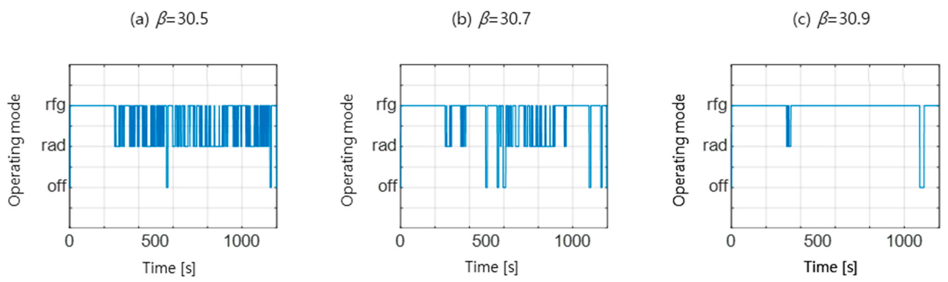
3.2. Mode Change Sensitivity in Conventional MPC

The prediction horizon cannot be arbitrarily extended due to computational complexity and the diminishing accuracy of long-term predictions. In this study, the prediction horizon is set to 60 s. Given that mode switching events are relatively infrequent over this duration, the penalty term β for excessive switching fails to effectively regulate mode transitions. Figure 10 illustrates the mode change behavior of conventional MPC for different values. The results indicate excessive sensitivity of mode change behavior to the weighting factor β, making it challenging to fine-tune the cost function. To address this issue, this study proposes an infinite-horizon MPC framework, which accounts for mode transitions over an extended horizon, improving stability and robustness.

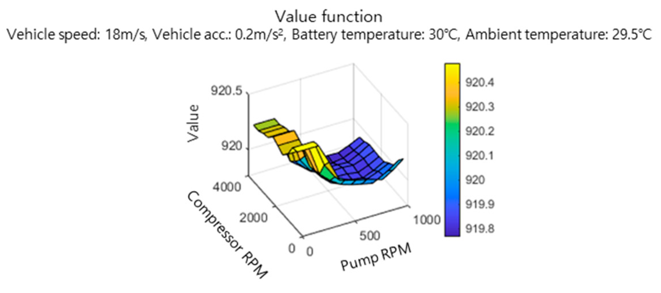
3.3. Infinity-Horizon MPC

The excessive sensitivity of mode change behavior in conventional MPC to control parameters arises from the low probability of a mode transition occurring within the prediction horizon. To mitigate the issue of overly frequent mode changes, we aim to design an MPC framework with an infinite horizon while maintaining minimal computational load.
The cost function for infinite-horizon MPC is defined as follows:
J x ( k ) , U ( k ) , k = i = k μ i k C x ( i ) , u ( i ) , w ( i ) , U ( k ) = u ( k ) , u ( k + 1 ) , ,
where C(k) is the cost function defined in (10) and μ is a discount factor that stabilizes the optimization by preventing the cost from increasing indefinitely.
The optimal cost and corresponding optimal control inputs are computed as follows:
J x ( k ) , k = min U ( k ) i = k μ i k C x ( i ) , u ( i ) , w ( i ) = min U ( k ) i = k k + n 1 μ i k C x ( i ) , u ( i ) , w ( i ) + i = k + n μ i k C x ( i ) , u ( i ) , w ( i ) = min U ¯ ( k ) i = k k + n 1 μ i k C x ( i ) , u ( i ) , w ( i ) + min U ( k + n ) i = k + n μ i k C x ( i ) , u ( i ) , w ( i ) = min U ¯ ( k ) i = k k + n 1 μ i k C x ( i ) , u ( i ) , w ( i ) + μ n min U ( 1 ) i = 1 μ i 1 C x ( i ) , u ( i ) , w ( i ) x ( 1 ) = x ( k + n ) ,
In this formulation, the first term in the bracket can be computed similarly to conventional MPC. However, the second term cannot be evaluated using the conventional approach. If statistical information about disturbances and system dynamics is available, the most probable value of the second term can be estimated in a statistical sense, i.e., as an expected value. This allows us to approximate the second term as follows:
V x 0 = min U ( 1 ) E w i = 1 μ i 1 C x ( i ) , u ( i ) , w ( i ) x ( 1 ) = x 0 .
This function represents the minimum expected cost from the current state x0 to an infinite time horizon, commonly referred to as the value function. The value function can be precomputed over the state space through a stochastic optimization process. One effective approach to such optimization is Stochastic Dynamic Programming (SDP). Within the SDP framework, the value function V(x) and the corresponding optimal policy are reformulated as
V ( x ) = min u C ( x , u , w ) + γ x X p x u , x V ( x ) ,
π ( x ) = arg min u C ( x , u , w ) + γ x X p x u , x V ( x ) ,
where x′ denotes the next state, X is the admissible state space, and pxu,x is the state transition probability from a state x to another state x′ under the control input u. The optimal policy can be obtained through the value iteration algorithm, as shown in Algorithm 1.
Algorithm 1 Value iteration
I n i t i a l i z e   V ( x )   t o   r a n d o m   v a l u e r e p e a t   u n t i l   δ < θ                 δ 0                 F o r   e a c h   s , a :                                 v V ( x )                                 V ( x ) min u x p x u , x [ C ( s , a ) + μ V ( x ) ]                                 δ min ( δ , | v V ( x ) | ) π ( x ) = arg min u x p x u , x [ C ( s , a ) + μ V ( x ) ]
An example of a value function obtained via SDP is illustrated in Figure 11. A more detailed explanation of this process can be found in the authors’ previous study [34]. Eventually, the optimal control problem can be expressed with a tractable function V(·) as follows:
J x ( k ) , k = min U ¯ ( k ) i = k k + n 1 μ i k C x ( i ) , u ( i ) , w ( i ) + μ n V x ( k + n ) .

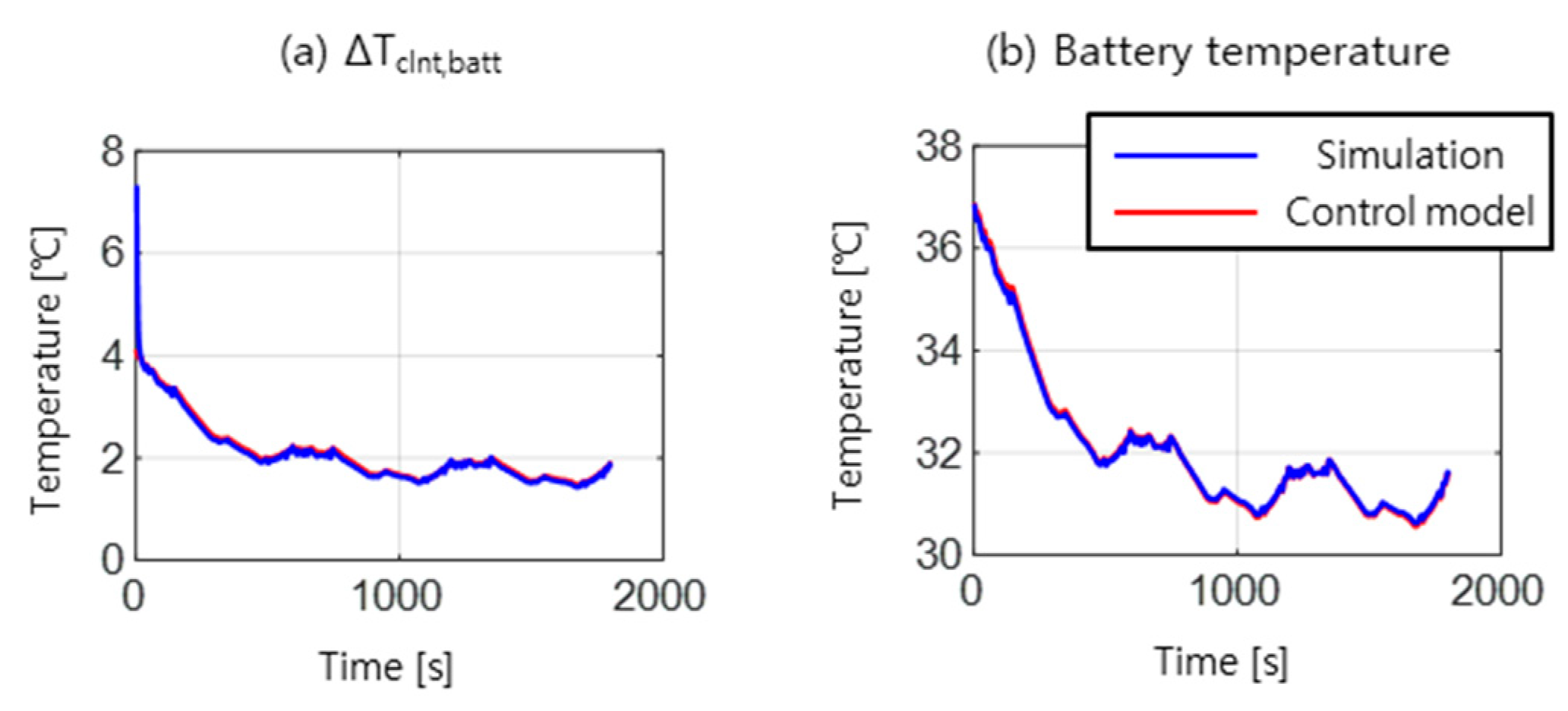
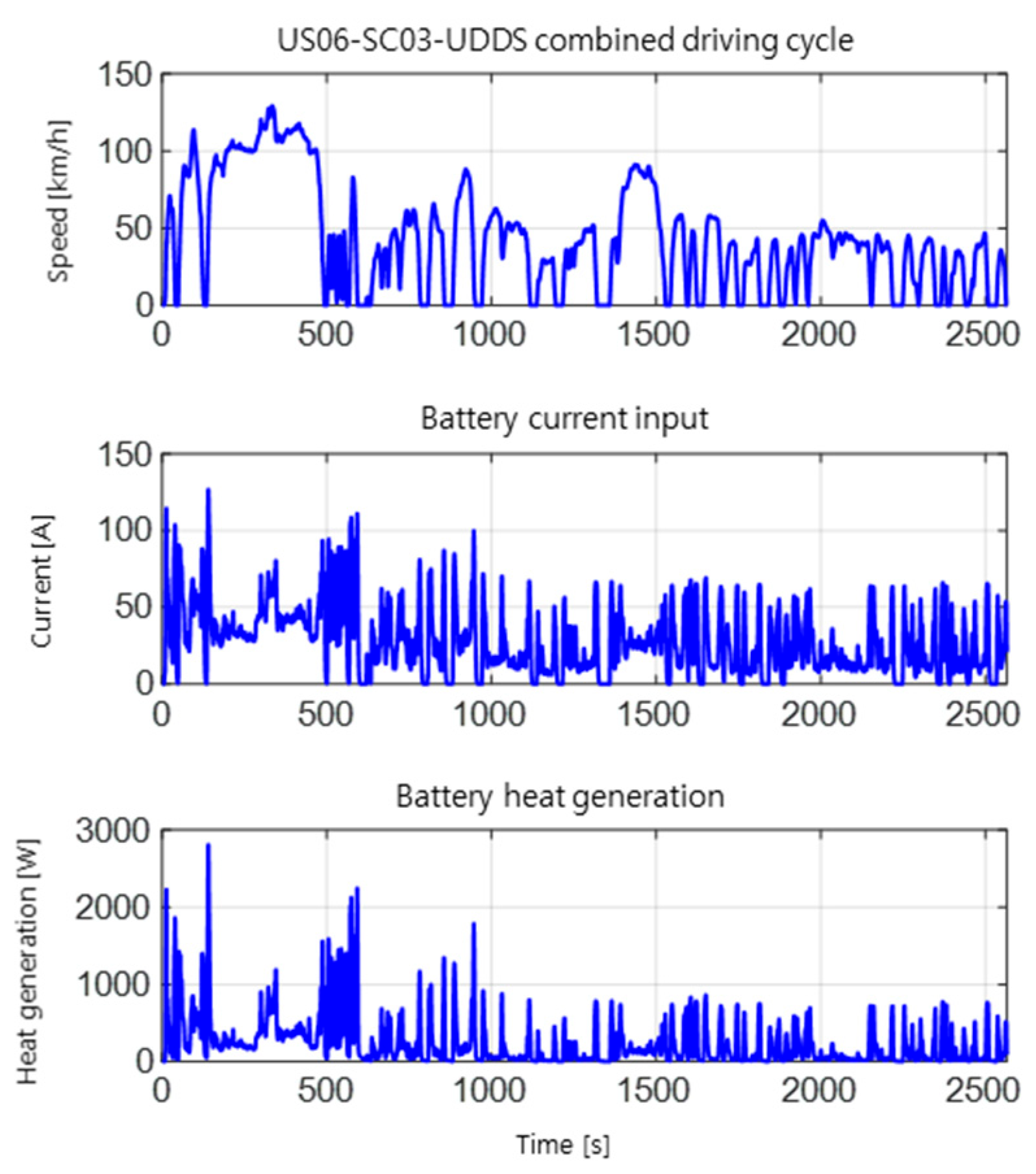
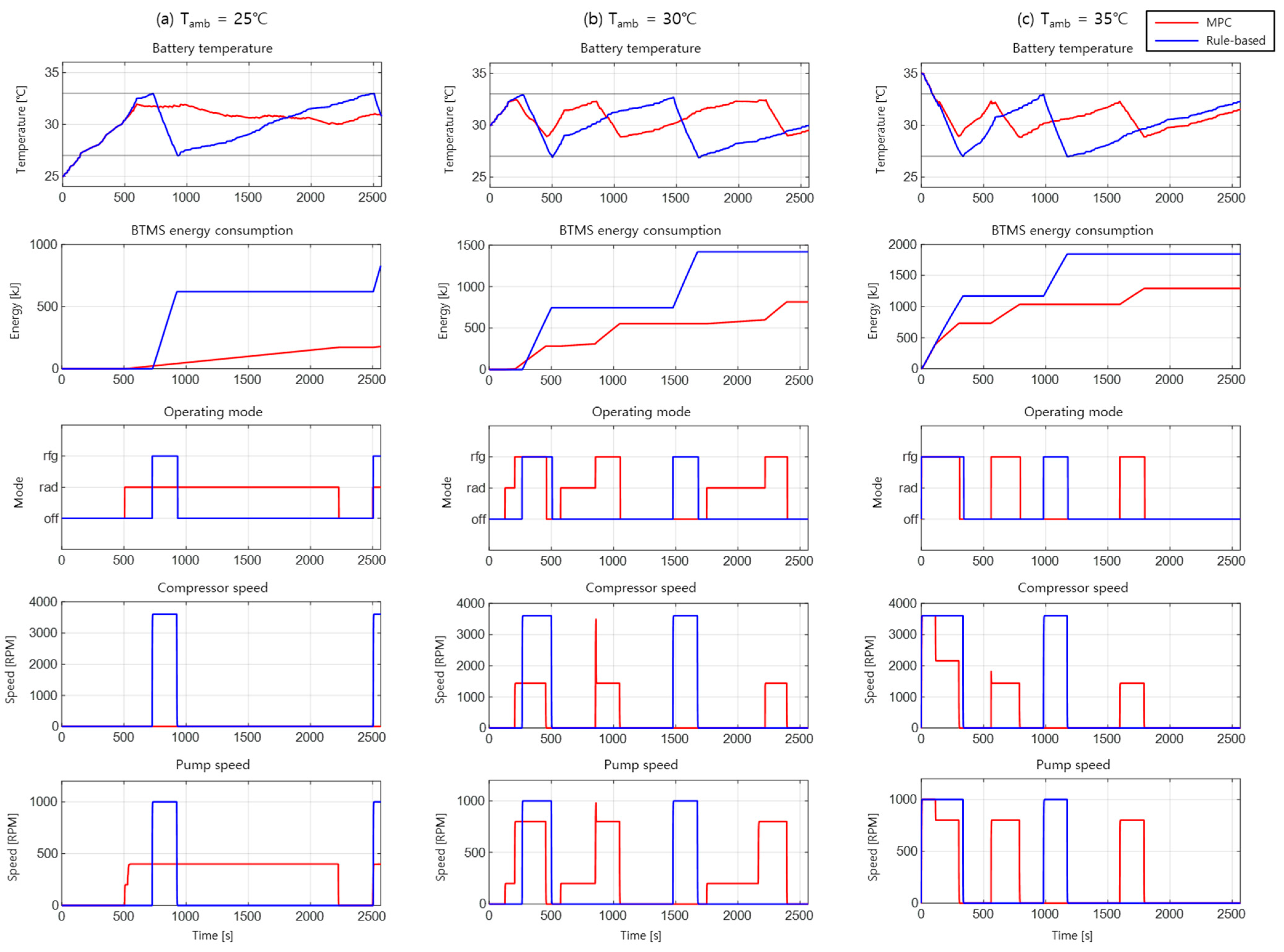
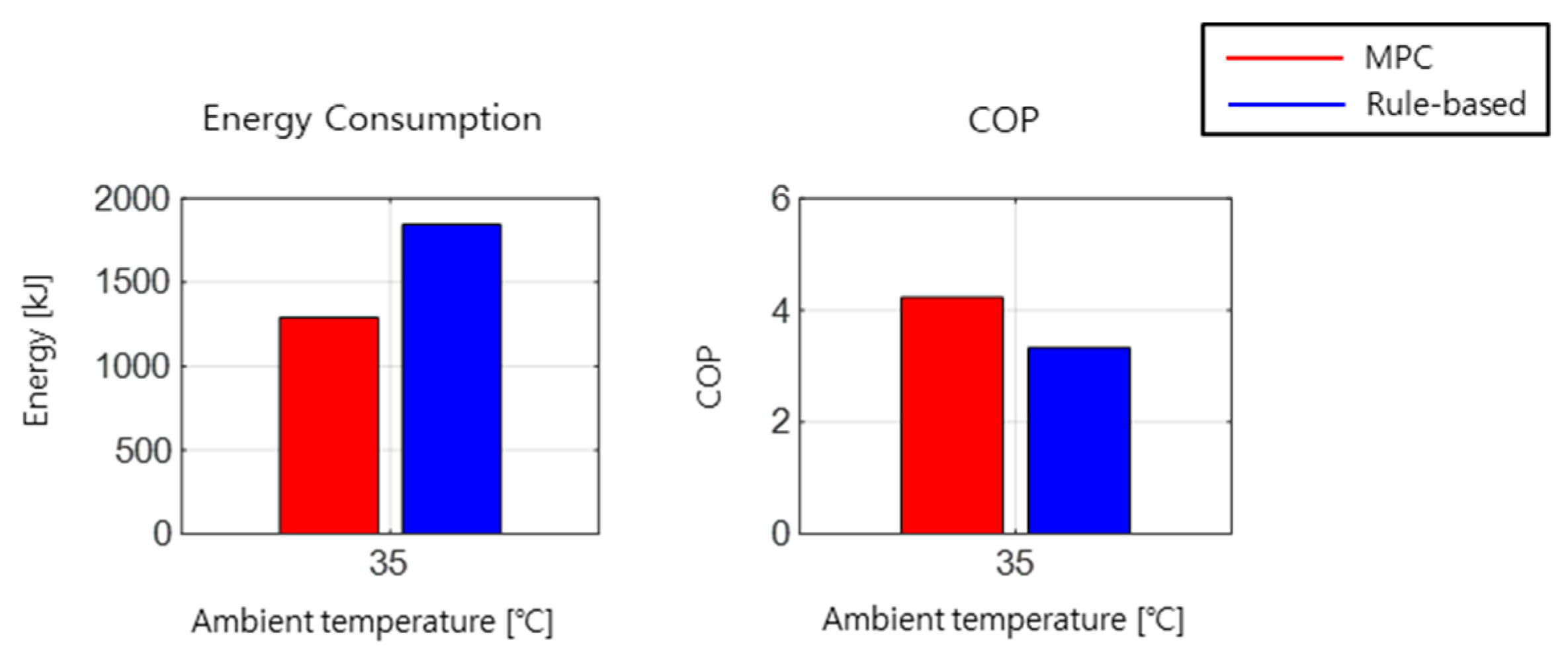
4. Controller Validation

To validate the performance of the proposed MPC, a comparative analysis was conducted against a conventional rule-based controller for the BTMS. The rule-based controller was configured to operate both actuators at maximum speed when the battery temperature exceeded the upper limit of the desired temperature range and to deactivate both actuators when the battery temperature dropped below the lower limit. Additionally, a minimum operating speed of 20% of the maximum speed was set for each actuator. The rule-based controller used for validation was designed as a hypothetical construct for the purpose of comparison.
For the simulation, a combined driving cycle consisting of US06, SC03, and UDDS cycles was used. The corresponding vehicle speed profile is depicted in the first graph of Figure 12. The second and third plots in Figure 12 depict the battery current and the heat generation of the battery under the given driving cycle. The control time step was set to 1 s and the prediction horizon for the proposed MPC was set to 60 s. Additionally, the disturbance or battery heat generation during prediction horizon was estimated using a zero-order-hold model.
Figure 13 presents the results for ambient temperatures of 25 °C, 30 °C, and 35 °C, respectively. In each figure, the red lines represent the results of the proposed controller, while the blue lines represent the results of the rule-based controller.
When the ambient temperature was 25 °C, the proposed controller actively utilized the radiator mode while avoiding the use of the refrigeration cycle mode. As a result, the proposed controller significantly reduced energy consumption compared to the rule-based controller while maintaining the battery temperature within the desired operating range.
When the ambient temperature was 30 °C, the proposed controller switched between the refrigeration cycle mode and the radiator mode based on battery heat generation and temperature conditions. This adaptive control strategy allowed the proposed controller to maintain the battery temperature within the desired operating range while reducing energy consumption by approximately 42.52% compared to the rule-based controller.
When the ambient temperature was 35 °C, neither the proposed controller nor the rule-based controller utilized the radiator mode due to the high ambient temperature. However, the optimized actuators in the proposed controller operated in more efficient regions compared to the rule-based controller. This is because the cost function of the proposed controller incorporates the power consumption characteristics of the actuators, allowing it to reflect and exploit their optimal efficiency ranges. As illustrated in Figure 14, the proposed control strategy achieves an average COP of 4.23 for the refrigeration cycle, whereas the rule-based control approach yields a COP of 3.33. This indicates that the proposed strategy operates the actuators within more energy-efficient regions of the cycle, thereby also reducing overall energy consumption. As a result, the proposed controller achieved a 30.05% reduction in energy consumption compared to the rule-based controller.
Additionally, a comparison of energy consumption with other studies employing different control strategies is presented in Table 1. Although a completely fair comparison is not possible due to differences in system specifications and simulation conditions, the effectiveness of the proposed method is evaluated by comparing the energy consumption reduction achieved under conditions as similar as possible. In particular, under the ambient temperature condition of 25 °C, the proposed control strategy effectively utilizes the radiator mode, which is not employed in other studies, resulting in a substantial reduction in BTMS energy consumption.
Figure 15 summarizes the validation results in terms of battery temperature regulation performance and energy consumption reduction. MPC regulates battery temperature in a tighter range while using less energy. Additionally, the third row of Figure 13 illustrates the mode change behavior of the EV BTMS under different ambient conditions. Compared to the mode change behavior of the conventional MPC shown in Figure 10, the proposed controller successfully suppressed unnecessary fluctuations in mode transitions. By reducing excessive mode changes, the proposed controller enhanced system stability and extended the lifespan of the BTMS components.

5. Conclusions

In this study, a Model Predictive Control (MPC) strategy for the Electric Vehicle Battery Thermal Management System (EV BTMS) was proposed to maintain the battery temperature within the optimal operating range while minimizing energy consumption. To ensure real-time performance and reliability, a high-fidelity model of the EV BTMS was developed using MATLAB/Simscape. Additionally, an artificial neural network (ANN)-based model was designed using data from the high-fidelity model. The ANN-based model was verified to accurately approximate the characteristics of the EV BTMS while maintaining a low computational load.
To address the issue of oscillatory control inputs observed in conventional MPC, a modified MPC framework was introduced. This framework incorporated a value function that captures the system’s characteristics beyond the prediction horizon, extending to an infinite time horizon.
The proposed controller was evaluated by comparing its performance with that of a conventional rule-based controller. The results demonstrated that under sufficiently low ambient temperatures, the proposed controller effectively utilized the radiator mode, leading to a 78.42% reduction in energy consumption compared to the rule-based controller. In scenarios where the ambient temperature was close to the battery temperature, the system dynamically adjusted its mode based on the battery’s heat generation and current temperature, resulting in a 42.52% reduction in energy consumption. Under high ambient temperatures, the proposed controller optimized actuator usage more efficiently than the rule-based controller, achieving a 30.05% reduction in energy consumption.
In all tested conditions, the proposed controller successfully maintained the battery temperature within the desired operating range. Additionally, the controller effectively suppressed unnecessary fluctuations in actuator operation, enhancing system stability and longevity.
This study aimed to achieve real-time operation by designing the controller with a reduced number of states while maintaining an acceptable level of model accuracy. For future work, we intend to improve control performance by incorporating a greater number of states into the MPC’s future cost by transitioning from an SDP-based value function to a learning-based value approximation approach.

Author Contributions

Conceptualization, K.N. and C.A.; methodology, C.A.; software, K.N.; validation, K.N.; formal analysis, K.N.; data curation, K.N.; writing—original draft preparation, K.N.; writing—review and editing, C.A.; visualization, K.N.; supervision, C.A.; project administration, C.A. All authors have read and agreed to the published version of the manuscript.

Funding

This research received no external funding.

Data Availability Statement

The raw data supporting the conclusions of this article will be made available by the authors upon request.

Conflicts of Interest

The authors declare no conflicts of interest.

References

  1. Millo, F.; Rolando, L.; Fuso, R.; Mallamo, F. Real CO2 emissions benefits and end user’s operating costs of a plug-in Hybrid Electric Vehicle. Appl. Energy 2014, 114, 563–571. [Google Scholar] [CrossRef]
  2. Kim, J.; Oh, J.; Lee, H. Review on battery thermal management system for electric vehicles. Appl. Therm. Eng. 2019, 149, 192–212. [Google Scholar] [CrossRef]
  3. Pesaran, A.A. Battery thermal management in EV and HEVs: Issues and solutions. Battery Man 2001, 43, 34–49. [Google Scholar]
  4. Arora, S.; Kapoor, A.; Shen, W. A novel thermal management system for improving discharge/charge performance of Li-ion battery packs under abuse. J. Power Sources 2018, 378, 759–775. [Google Scholar] [CrossRef]
  5. Lei, Z.; Zhang, Y.; Lei, X. Improving temperature uniformity of a lithium-ion battery by intermittent heating method in cold climate. Int. J. Heat Mass Transf. 2018, 121, 275–281. [Google Scholar] [CrossRef]
  6. Lu, M.; Zhang, X.; Ji, J.; Xu, X.; Zhang, Y. Research progress on power battery cooling technology for electric vehicles. J. Energy Storage 2020, 27, 101–155. [Google Scholar] [CrossRef]
  7. Xu, J.M.; Zhang, C.Z.; Wan, Z.M.; Chen, X.; Chan, S.H.; Tu, Z.K. Progress and perspectives of integrated thermal management systems in PEM fuel cell vehicles: A review. Renew. Sustain. Energy Rev. 2022, 155, 111908. [Google Scholar] [CrossRef]
  8. Feng, X.; Ouyang, M.; Liu, X.; Lu, L.; Xia, Y.; He, X. Thermal runaway mechanism of lithium ion battery for electric vehicles: A review. Energy Storage Mater. 2018, 10, 246–267. [Google Scholar] [CrossRef]
  9. Kshetrimayum, K.S.; Yoon, Y.-G.; Gye, H.-R.; Lee, C.-J. Preventing heat propagation and thermal runaway in electric vehicle battery modules using integrated PCM and micro-channel plate cooling system. Appl. Therm. Eng. 2019, 159, 113797. [Google Scholar] [CrossRef]
  10. Chavan, S.; Venkateswarlu, B.; Prabakaran, R.; Salman, M.; Joo, S.W.; Choi, G.S.; Kim, S.C. Thermal runaway and mitigation strategies for electric vehicle lithium-ion batteries using battery cooling approach: A review of the current status and challenges. J. Energy Storage 2023, 72, 108569. [Google Scholar] [CrossRef]
  11. Suresh, C.; Awasthi, A.; Kumar, B.; Im, S.-k.; Jeon, Y. Advances in battery thermal management for electric vehicles: A comprehensive review of hybrid PCM-metal foam and immersion cooling technologies. Renew. Sustain. Energy Rev. 2025, 208, 115021. [Google Scholar] [CrossRef]
  12. Akinlabi, A.A.H.; Solyali, D. Configuration, design, and optimization of air-cooled battery thermal management system for electric vehicles: A review. Renew. Sustain. Energy Rev. 2020, 125, 109815. [Google Scholar] [CrossRef]
  13. Xu, J.; Guo, Z.; Xu, Z.; Zhou, X.; Mei, X. A systematic review and comparison of liquid-based cooling system for lithium-ion batteries. eTransportation 2023, 17, 100242. [Google Scholar] [CrossRef]
  14. Luo, J.; Zou, D.; Wang, Y.; Wang, S.; Huang, L. Battery thermal management systems (BTMs) based on phase change material (PCM): A comprehensive review. Chem. Eng. J. 2022, 430, 132741. [Google Scholar] [CrossRef]
  15. Gharehghani, A.; Rabiei, M.; Mehranfar, S.; Saeedipour, S.; Mahmoudzadeh Andwari, A.; García, A.; Reche, C.M. Progress in battery thermal management systems technologies for electric vehicles. Renew. Sustain. Energy Rev. 2024, 202, 114654. [Google Scholar] [CrossRef]
  16. Lee, J.T.; Kwon, S.; Lim, Y.; Chon, M.S.; Kim, D. Effect of air-conditioning on driving range of electric vehicle for various driving modes; SAE Technical Paper 2013-01-0040. In Proceedings of the Asia Pacific Automotive Engineering Conference, Bangkok, Thailand, 1–3 April 2013. [Google Scholar] [CrossRef]
  17. Huang, G.; Wang, S.; Xu, X. A robust model predictive control strategy for improving the control performance of air-conditioning systems. Energy Convers. Manag. 2009, 50, 2650–2658. [Google Scholar] [CrossRef]
  18. Cen, J.; Jiang, F. Li-ion power battery temperature control by a battery thermal management and vehicle cabin air conditioning integrated system. Energy Sustain. Dev. 2020, 57, 141–148. [Google Scholar] [CrossRef]
  19. Aprea, C.; Mastrullo, R.; Renno, C. Fuzzy control of the compressor speed in a refrigeration plant. Int. J. Refrig. 2004, 27, 639–648. [Google Scholar] [CrossRef]
  20. Ma, Y.; Duan, P.; Sun, Y.; Chen, H. Equalization of Lithium-Ion Battery Pack Based on Fuzzy Logic Control in Electric Vehicle. IEEE Trans. Ind. Electron. 2018, 65, 6762–6771. [Google Scholar] [CrossRef]
  21. Zhou, H.; Jia, F.; Jing, H.; Liu, Z.; Güvenç, L. Coordinated Longitudinal and Lateral Motion Control for Four Wheel Independent Motor-Drive Electric Vehicle. IEEE Trans. Veh. Technol. 2018, 67, 3782–3790. [Google Scholar] [CrossRef]
  22. Behrooz, F.; Mariun, N.; Marhaban, M.H.; Mohd Radzi, M.A.; Ramli, A.R. Review of Control Techniques for HVAC Systems—Nonlinearity Approaches Based on Fuzzy Cognitive Maps. Energies 2018, 11, 495. [Google Scholar] [CrossRef]
  23. Liu, Y.; Zhang, J. Self-adapting J-type air-based battery thermal management system via model predictive control. Appl. Energy 2020, 263, 114640. [Google Scholar] [CrossRef]
  24. Ma, Y.; Ding, H.; Mou, H.; Gao, J. Battery thermal management strategy for electric vehicles based on nonlinear model predictive control. Measurement 2021, 186, 110115. [Google Scholar] [CrossRef]
  25. Park, S.; Ahn, C. Computationally Efficient Stochastic Model Predictive Controller for Battery Thermal Management of Electric Vehicle. IEEE Trans. Veh. Technol. 2020, 69, 8407–8419. [Google Scholar] [CrossRef]
  26. He, H.; Jia, H.; Huo, W.; Yan, M. Stochastic Dynamic Programming of Air Conditioning System for Electric Vehicles. Energy Procedia 2017, 105, 2518–2524. [Google Scholar] [CrossRef]
  27. Tang, W.; Zhang, Y.J. A Model Predictive Control Approach for Low-Complexity Electric Vehicle Charging Scheduling: Optimality and Scalability. IEEE Trans. Power Syst. 2017, 32, 1050–1063. [Google Scholar] [CrossRef]
  28. Tian, Z.; Gan, W.; Zhang, X.L.; Gu, B.; Yang, L. Investigation on an integrated thermal management system with battery cooling and motor waste heat recovery for electric vehicle. Appl. Therm. Eng. 2018, 136, 16–27. [Google Scholar] [CrossRef]
  29. Jani, D.B.; Mishra, M.; Sahoo, P.K. Application of artificial neural network for predicting performance of solid desiccant cooling systems—A review. Renew. Sustain. Energy Rev. 2017, 80, 352–366. [Google Scholar] [CrossRef]
  30. Al-Waeli, A.H.A.; Sopian, K.; Yousif, J.H.; Kazem, H.A.; Boland, J.; Chaichan, M.T. Artificial neural network modeling and analysis of photovoltaic/thermal system based on the experimental study. Energy Convers. Manag. 2019, 186, 368–379. [Google Scholar] [CrossRef]
  31. Elsheikh, A.H.; Sharshir, S.W.; Abd Elaziz, M.; Kabeel, A.E.; Wang, G.; Zhang, H. Modeling of solar energy systems using artificial neural network: A comprehensive review. Sol. Energy 2019, 180, 622–639. [Google Scholar] [CrossRef]
  32. The Mathworks Inc. Electric Vehicle Thermal Management. 2021. Available online: https://www.mathworks.com/help/hydro/ug/sscfluids_ev_thermal_management.html (accessed on 9 April 2020).
  33. Xia, G.D.; Cao, L.; Bi, G.L. A review on battery thermal management in electric vehicle application. J. Power Sources 2017, 367, 90–105. [Google Scholar] [CrossRef]
  34. Park, S.; Ahn, C. Optimal Cooling Controller Design for Battery Thermal Management System of Electric Vehicle. IEEE Trans. Transp. Electrif. 2025, 11, 1529–1540. [Google Scholar] [CrossRef]
  35. Amini, M.R.; Kolmanovsky, I.; Sun, J. Hierarchical MPC for Robust Eco-Cooling of Connected and Automated Vehicles and Its Application to Electric Vehicle Battery Thermal Management. IEEE Trans. Control Syst. Technol. 2021, 29, 316–328. [Google Scholar] [CrossRef]
  36. Xie, Y.; Wang, C.; Hu, X.; Lin, X.; Zhang, Y.; Li, W. An MPC-Based Control Strategy for Electric Vehicle Battery Cooling Considering Energy Saving and Battery Lifespan. IEEE Trans. Veh. Technol. 2020, 69, 14657–14673. [Google Scholar] [CrossRef]
  37. Fan, Y.; Zuo, X.; Zhan, D.; Zhao, J.; Zhang, G.; Wang, H.; Wang, K.; Yang, S.; Tan, X. A novel control strategy for active battery thermal management systems based on dynamic programming and a genetic algorithm. Appl. Therm. Eng. 2023, 233, 121113. [Google Scholar] [CrossRef]
Figure 1. Thermal management system of an electric vehicle.
Wevj 16 00279 g001
Figure 2. Schematic diagram of the thermal management system of an electric vehicle. (a) Refrigeration mode. (b) Radiator mode.
Wevj 16 00279 g002
Figure 3. Input/output signals and required internal functions for (a) Refrigeration cycle mode and (b) Radiator mode.
Wevj 16 00279 g003
Figure 4. ANN-based modeling approach for (a) Refrigeration cycle mode and (b) Radiator mode.
Wevj 16 00279 g004
Figure 5. Compressor performance characteristics, (a) mass flow rate, (b) overall compressor efficiency, and (c) power conversion efficiency of compressor motor.
Wevj 16 00279 g005
Figure 6. Pump performance characteristics, (a) mass flow rate, (b) mechanical power of pump, and (c) power conversion efficiency of pump motor.
Wevj 16 00279 g006
Figure 7. Simulation model of electric vehicle thermal management system, implemented in MATLAB/Simscape [32].
Wevj 16 00279 g007
Figure 8. Validation results of refrigeration cycle mode: (a) pressure and enthalpy, (b) coolant temperature, (c) battery temperature.
Wevj 16 00279 g008
Figure 9. Validation results of refrigeration cycle mode: (a) pump mechanical power comparison result, (b) pump torque comparison result.
Wevj 16 00279 g009
Figure 10. Mode change behavior of conventional MPC: (a) result with β = 30.5, (b) result with β = 30.7, (c) result with β = 30.9.
Wevj 16 00279 g010
Figure 11. Example of value function.
Wevj 16 00279 g011
Figure 12. US06-SC03-UDDS combined driving cycle and corresponding battery current input and battery heat generation.
Wevj 16 00279 g012
Figure 13. Controller validation results when (a) the ambient temperature is 25 °C, (b) the ambient temperature is 30 °C, and (c) the ambient temperature is 35 °C.
Wevj 16 00279 g013
Figure 14. Energy consumption and refrigeration cycle COP under ambient temperature 35 °C condition.
Wevj 16 00279 g014
Figure 15. (a) Battery temperature regulation performance; (b) energy consumption reduction performance.
Wevj 16 00279 g015
Table 1. Control strategy comparison.
Control StrategyHMPC [35]IMPC [36]DP-GA [37]OursOursOurs
Driving cycleUDDSNEDCCombinedCombinedCombinedCombined
Ambient temperature30 °C27 °C30 °C25 °C30 °C35 °C
Energy consumption reduction25%24.5%22.4%78.42%42.52%30.05%
Disclaimer/Publisher’s Note: The statements, opinions and data contained in all publications are solely those of the individual author(s) and contributor(s) and not of MDPI and/or the editor(s). MDPI and/or the editor(s) disclaim responsibility for any injury to people or property resulting from any ideas, methods, instructions or products referred to in the content.

