Article

Deadbeat Predictive Current Control Strategy for Permanent Magnet-Assisted Synchronous Reluctance Motor Based on Adaptive Sliding Mode Observer

School of Electrical Engineering and Automation, Harbin Institute of Technology, Harbin 150000, China
*
Author to whom correspondence should be addressed.
World Electr. Veh. J. 2025, 16(4), 202; https://doi.org/10.3390/wevj16040202
Submission received: 14 February 2025 / Revised: 24 March 2025 / Accepted: 25 March 2025 / Published: 1 April 2025

Abstract

:
To suppress current and torque ripples, this paper proposes a novel deadbeat predictive current control strategy based on an adaptive sliding mode observer for permanent magnet-assisted synchronous reluctance motor (PMa-SynRM) drives. The parameter sensitivity of predictive current control is analyzed, and a sliding mode observer is employed to calculate the parameter disturbances for voltage compensation. The predicted current is utilized instead of the sampled current to address the one-step delay issue, effectively suppressing the adverse effects of parameter mismatch in predictive control. The adaptive control parameter module suppresses the chattering phenomenon in sliding mode control and enhances the observer’s adaptability under varying load conditions. The effectiveness of the proposed strategy is validated on a 2.2 kW PMa-SynRM platform. This strategy can suppress current and torque fluctuations under complex operating conditions, which has significant implications for electric vehicle drive control.

1. Introduction

The permanent magnet-assisted synchronous reluctance motor (PMa-SynRM) offers numerous advantages including high efficiency, high reliability, high power density, and low cost, leading to its widespread application in electric vehicle drives, wind power generation, and household appliances [1,2,3,4]. In SynRM vector control systems, the design of the current loop directly determines the dynamic performance and disturbance rejection capability of the motor. A high-performance current loop can not only effectively reduce current fluctuations and torque ripples but also maintain system stability under changing loads and external disturbances, which is of great significance for electric vehicle drive systems operating under variable working conditions. Therefore, to enhance current loop performance, researchers have proposed and developed various current control strategies. Among these, hysteresis control, proportional–integral (PI) control, and predictive current control are commonly employed methods.
Hysteresis control features fast dynamic response and strong robustness. However, its switching frequency varies with current changes and is difficult to control. Moreover, due to the hysteresis band, steady-state current accuracy is not ideal [5,6,7,8,9]. PI control offers advantages such as simple structure and good steady-state performance. However, the nonlinearity and strong coupling characteristics of PMa-SynRM are significant, and PI control based on linear assumptions has limited accuracy, potentially leading to control lag or overshoot during rapid load changes [10,11,12,13,14,15,16,17]. Predictive current control based on the discrete model of PMa-SynRM demonstrates superior dynamic performance and strong nonlinear adaptability compared with the aforementioned control methods. This approach optimizes control inputs in real time by predicting future system behavior and can be classified into two categories: model predictive control (MPC) and deadbeat predictive current control (DPCC). MPC predicts system responses over a future time horizon using the motor model and calculates optimal control inputs in real time through a cost function. Reference [18] proposed a method combining sliding mode control theory with MPC, which is completely model-independent with relatively low computational burden and good robustness. However, it has variable switching frequency and difficult parameter tuning. To suppress the impact of switching frequency on motor performance, reference [19] proposed an improved MPC method based on reference voltage vector prediction and cascade structure. This method offers excellent steady-state performance and easy implementation, but its switching performance may deteriorate under high-speed conditions, and it shows high parameter sensitivity. Reference [20] achieved compensation by predicting current changes during delay time, offering low harmonic content and fast dynamic response, but poor adaptability under low-load conditions. Although MPC exhibits outstanding control performance and strong multi-constraint handling capabilities, its high computational burden remains the major challenge. Practical applications require the prediction of system states over multiple future time steps within each control period, leading to exponential growth in computational complexity with increased prediction horizon. Additionally, this control method has strict requirements for solution time.
In comparison, deadbeat predictive current control offers lower computational burden and excellent motor control performance [21,22,23,24,25,26,27,28,29]. This method utilizes the discrete mathematical model of the motor to achieve reference current values within one sampling period by selecting optimal voltage vectors. Reference [30] proposed a deadbeat predictive current control method with global optimization of voltage vectors, employing multi-step calculations to reduce burden and improve dynamic response by 40%. However, it encounters current vector magnitude overshoot under heavy load conditions. Reference [31] introduced a data-driven model-free predictive current control, effectively enhancing system disturbance rejection and parameter robustness, but with compromised dynamic performance and cumbersome offline training requirements. To address significant iron losses during high-speed motor operation, reference [32] established a novel predictive model considering core losses, achieving faster dynamic response and better iron loss suppression, though requiring high parameter accuracy. Reference [33] designed an integral sliding mode disturbance controller to improve parameter robustness while addressing the one-step delay error in predictive current control, incorporating a super-twisting algorithm for further performance enhancement. However, it features high computational load and an inability to suppress large disturbances. Reference [34] developed a moving horizon estimator to evaluate disturbances caused by the back electromotive force (EMF) and parameter variations, improving dynamic performance, steady-state accuracy, and parameter robustness. Nevertheless, this approach substantially increases computational resource requirements and demands relatively accurate initial parameter estimates. Under the premise of low computational burden, the aforementioned methods cannot simultaneously resolve both parameter sensitivity and prediction delay issues in deadbeat predictive current control. Reference [35] proposed a current predictive controller based on a variable-speed sliding mode reaching law, which can effectively suppress the negative impact of parameter mismatch on control performance while maintaining the excellent dynamic response characteristics of conventional DPCC methods. However, this sliding mode reaching law demonstrates poor adaptability, and its performance cannot be guaranteed under complex operating conditions. Reference [36] investigated an iterative sliding mode observer that demonstrates excellent oscillation suppression performance under variable speed conditions; however, it imposes a significant computational burden and high hardware requirements.
Therefore, this paper proposes a deadbeat predictive current control strategy based on an adaptive sliding mode observer for PMa-SynRM drive systems. The strategy achieves compensation for single-step sampling delay and the suppression of parameter sensitivity through compensated current prediction and the tracking of system voltage disturbances caused by parameter mismatch. During the deadbeat predictive current control process, sliding mode convergence eliminates errors between sampled and predicted currents, while the feedforward compensation of the reference voltage suppresses current and torque ripples during motor operation. To further enhance suppression effects and parameter robustness, an adaptive control parameter tuning module is introduced, which adjusts convergence speed according to motor states, thereby improving the adaptability of the proposed strategy under various operating conditions. When electric vehicles encounter external environmental disturbances such as changes in road gradient, this control strategy can maintain stable driving performance.

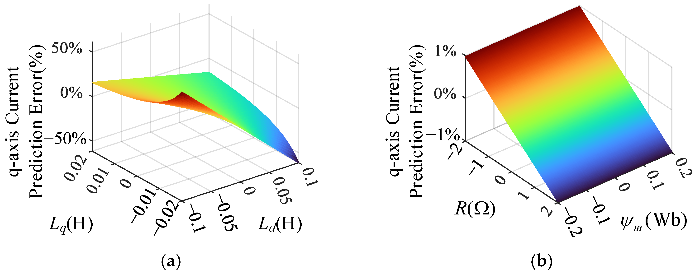
2. Parameter Sensitivity Analysis of Deadbeat Predictive Current Control Strategy

In the synchronous rotating reference frame, the voltage equations of PMa-SynRM are shown in Equation (1):
u d = R i d + L d d i d d t ω e L q i q + ω e Ψ m u q = R i q + L q d i q d t + ω e L d i d ,
where ud, uq, id, and iq are the d-axis and q-axis voltages and currents, respectively; ωe is the electrical angular velocity (rad/s); Ψm, R, Ld, and Lq represent the permanent magnet flux linkage, stator resistance, and d-axis and q-axis inductances, respectively.
Using the forward Euler discretization method, Equation (1) can be converted into Equation (2) as follows:
i d ( k + 1 ) i q ( k + 1 ) = F ( k ) i d ( k ) i q ( k ) + G u d ( k ) u q ( k ) + M ( k ) ,
where F ( k ) = 1 T R L d T ω e ( k ) L q L d T ω e ( k ) L d L q 1 T R L q , G = T L d 0 0 T L q , M ( k ) = T Ψ m L d ω e ( k ) 0 .
In conventional deadbeat predictive current control, according to Equation (2), after one modulation period, the predicted reference voltage can be expressed as:
u d ( k ) u q ( k ) = G 1 i d ( k + 1 ) i q ( k + 1 ) F ( k ) i d ( k ) i q ( k ) M ( k ) ,
where id* (k + 1) and iq* (k + 1) are the d-axis and q-axis current references at the (k + 1)th instant, respectively. The block diagram of deadbeat predictive current control is shown in Figure 1.
Based on Equation (3), the predictive current control model includes four model parameters (Ψm, R, Ld, and Lq). Since deadbeat predictive current control is a parameter-model-based control method, the parameter sensitivity of deadbeat predictive current control is analyzed as follows.
Ψm, R, Ld, and Lq are the nominal values of the PMa-SynRM parameters, which can be determined through offline measurement or prior knowledge; Ψm0, R0, Ld0, and Lq0 represent the actual values of the motor parameters.
The prediction using actual parameter values is shown in Equation (4):
i d 0 ( k + 1 ) i q 0 ( k + 1 ) = F 0 ( k ) i d ( k ) i q ( k ) + G 0 u d ( k ) u q ( k ) + M 0 ( k ) ,
where F 0 ( k ) = 1 T R 0 L d 0 T ω e ( k ) L q 0 L d 0 T ω e ( k ) L d 0 L q 0 1 T R 0 L q 0 , G 0 = T L d 0 0 0 T L q 0 , M 0 ( k ) = T Ψ m 0 L d 0 ω e ( k ) 0 , id0 (k + 1) and iq0 (k + 1) are the accurate current prediction values for the next sampling instant.
Therefore, under parameter disturbances, the error between the predicted current using nominal values and the accurate predicted current can be expressed as:
e d = i d ( k + 1 ) i d 0 ( k + 1 ) e q = i q ( k + 1 ) i q 0 ( k + 1 ) .
Combining Equations (2) and (4), it is obtained that:
e d = T R Δ L d L d Δ R L d ( L d + Δ L d ) i d ( k ) + T ω e ( k ) L d Δ L q L q Δ L d L d ( L d + Δ L d ) i q ( k ) T Δ L d L d ( L d + Δ L d ) u d ( k ) + T ω e ( k ) Ψ m Δ L d Δ Ψ m L d L d ( L d + Δ L d ) e q = T ω e ( k ) L d Δ L q L q Δ L d L q ( L q + Δ L q ) i d ( k ) + T R Δ L q L q Δ R L q ( L q + Δ L q ) i q ( k ) T Δ L q L q ( L q + Δ L q ) u q ( k ) ,
where ΔR = RR0, ΔLd = LdLd0, ΔLq = LqLq0, and ΔΨm = ΨmΨm0.
Based on Equation (6), the relationship diagrams between the prediction errors of d-axis and q-axis currents and motor parameter mismatches are plotted (all parameter error ranges are within ±70%), as shown in Figure 2 and Figure 3. Figure 2a indicates that when the Ld error is ±0.1 H and the Lq error is ±0.02 H, a 5% error occurs in the d-axis predicted current. Figure 2b shows that when the resistance error is ±2 Ω and the flux linkage error is ±0.2 Wb, a 2% error occurs in the d-axis predicted current, indicating that inductance parameter mismatch has a relatively significant impact on d-axis current prediction. Figure 3a demonstrates that when the Ld error is ±0.1 H and the Lq error is ±0.02 H, a 50% error occurs in the q-axis predicted current. Figure 3b shows that when the resistance error is ±2 Ω, a 1% error occurs in the q-axis predicted current, while flux linkage parameter mismatch has no effect on q-axis current prediction. Inductance parameter mismatch has a particularly significant impact on q-axis current prediction.
From the above analysis, it can be concluded that parameter mismatch has a significant negative impact on conventional deadbeat predictive control, and the accuracy of d-axis and q-axis inductance parameters plays a crucial role in current prediction.

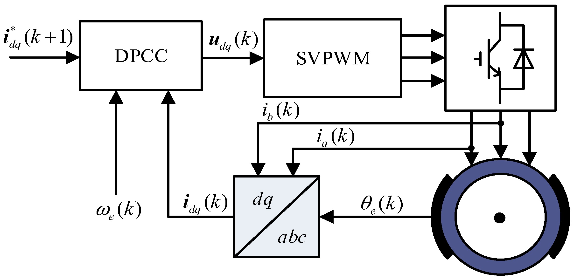
3. Deadbeat Predictive Current Control Strategy Based on Adaptive Sliding Mode Observer

3.1. Principle Analysis of the Proposed Control Strategy

Based on the discrete mathematical model of PMa-SynRM, the parameter sensitivity of conventional deadbeat predictive current control was analyzed above. To achieve better control performance under parameter mismatch and one-step sampling delay, a predictive current control strategy based on an adaptive sliding mode observer is proposed, which can track system disturbances caused by parameter mismatch and provide predictive compensation for sampled current. The outputs of the adaptive observer, namely the predicted current and parameter disturbance estimates, compensate for sampling delay and voltage reference, respectively. The principle diagram of the control strategy is shown in Figure 4.
Considering parameter disturbances during motor operation, the voltage equations of PMa-SynRM can be rewritten as Equations (7) and (8):
u d = L d d i d d t + R i d ω e L q i q + ω e Ψ f + f d d f d d t = F d ,
u q = L q d i q d t + R i q + ω e L i d + f q d f q d t = F q ,
where fd and fq represent the d-axis and q-axis parameter disturbances which can be expressed in the form of Equation (9), and Fd and Fq are the rates of change in parameter disturbance.
f d = Δ L d d i d d t + Δ R i d Δ L q ω e i q + Δ Ψ f ω e f q = Δ L q d i q d t + Δ R i q + Δ L d ω e i d .
To implement parameter disturbance compensation and current prediction, the sliding mode observer is designed in the following form:
u d = L d d i ^ d d t + R i ^ d ω e L q i q + ω e Ψ f + f ^ d + U dsmo d f ^ d d t = g d U dsmo ,
u q = L q d i ^ q d t + R i ^ q + ω e L d i d + f ^ q + U qsmo d f ^ q d t = g q U qsmo ,
where i ^ d and i ^ q are the d-axis and q-axis current prediction values; f ^ d and f ^ q are the parameter disturbance estimates; Udsmo and Uqsmo are the sliding mode observation functions; and gd and gq are the sliding mode parameters.
Subtracting Equation (10) from Equation (7), and Equation (11) from Equation (8), it is obtained that:
d e 1 d t = R L d e 1 1 L d e 2 1 L d U dsmo d e 2 d t = g d U dsmo F d ,
d e 3 d t = R L q e 3 1 L q e 4 1 L q U qsmo d e 4 d t = g q U qsmo F q ,
where e 1 = i ^ d i d , e 2 = f ^ d f d , e 3 = i ^ q i q , and e 4 = f ^ q f q .
The linear sliding mode surfaces are adopted in this paper, which can be expressed as:
s d = i ^ d i d s q = i ^ q i q .
The exponential reaching law, as shown in Equation (15), is employed to design the sliding mode control functions:
d s d t = k 1 sgn ( s ) λ s ,
where k1 and λ are exponential reaching rate parameters, both with positive values. Under the condition of s(t1) = 0, integrating Equation (15) from 0 to t1 yields the reaching time:
t 1 = | s ( 0 ) | 0 t 1 λ s d t k 1 .
From Equation (16), it can be seen that larger values of k1 and λ result in faster convergence. However, due to the inherent characteristics of sliding mode control, increasing the exponential reaching rate parameters also leads to heightened chattering levels. Therefore, in practical applications, these parameters should be adjusted according to actual requirements to achieve a balance between convergence speed and chattering.
Substituting Equation (14) into Equation (15) yields Equation (17):
d e 1 d t = k 1 sgn ( e 1 ) λ e 1 d e 3 d t = k 1 sgn ( e 3 ) λ e 3 .
By substituting Equations (12) and (13) into Equation (17), Equation (18) is obtained:
R L d e 1 1 L d e 2 1 L d U dsmo = k 1 sgn ( e 1 ) λ e 1 R L q e 3 1 L q e 4 1 L q U qsmo = k 1 sgn ( e 3 ) λ e 3 .
From Equation (18), the expressions for sliding mode control functions can be derived as:
U dsmo = ( L d λ R ) e 1 + k 1 L d sgn ( e 1 ) U qsmo = ( L q λ R ) e 3 + k 1 L q sgn ( e 3 ) .
Using the forward Euler discretization method to discretize Equation (10), it is obtained that:
i ^ d ( k + 1 ) = 1 R T L d i ^ d ( k ) + T L d u d ( k ) + T ω e ( k ) L q L d i q ( k ) T Ψ f L d ω e ( k ) T L d f ^ d ( k ) T L d U dsmo ( k ) f ^ d ( k + 1 ) = f ^ d ( k ) + T g d U dsmo ( k )
Using the forward Euler discretization method to discretize Equation (11), it is obtained that:
i ^ q ( k + 1 ) = 1 R T L q i ^ q ( k ) + T L q u q ( k ) T ω e ( k ) L d L q i d ( k ) T L q f ^ q ( k ) T L q U qsmo ( k ) f ^ q ( k + 1 ) = f ^ q ( k ) + T g q U qsmo ( k ) .
Using predicted currents i ^ d ( k + 1 ) and i ^ q ( k + 1 ) to replace the d-axis and q-axis sampled currents can effectively compensate for the one-step delay issue in deadbeat predictive current control. Compensating d-axis and q-axis voltages with parameter disturbance estimates f ^ d ( k + 1 ) and f ^ q ( k + 1 ) can suppress the system impacts caused by parameter variations during PMa-SynRM operation, thereby reducing current and torque ripples.

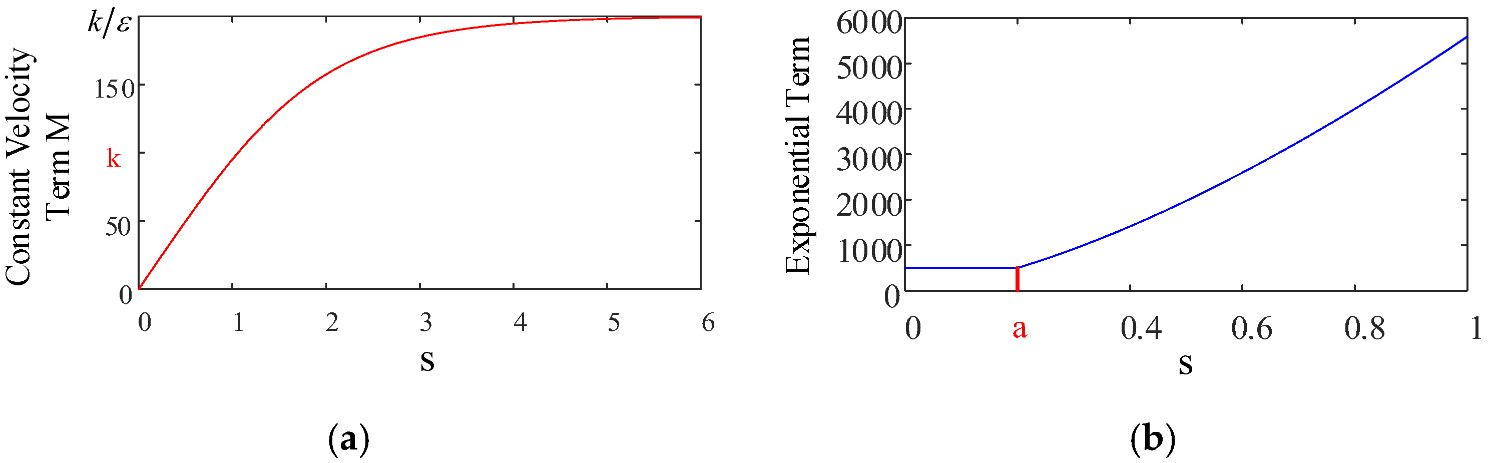
3.2. Stability Analysis and Parameter Design

To analyze the stability of the proposed method, the following Lyapunov function is selected:
V = 1 2 s T s .
The stability condition for the sliding mode observer is V ˙ 0 , that is:
V ˙ d = s d s ˙ d = e 1 e ˙ 1 0 V ˙ q = s q s ˙ q = e 3 e ˙ 3 0 .
According to Equations (12) and (19), the first inequality of Equation (23) can be rewritten as:
V ˙ d = 1 L d e 1 ( R e 1 + e 2 + U dsmo ) = 1 L d ( L d λ e 1 2 + e 1 ( e 2 sgn ( e 1 ) + k 1 L d ) ) .
To ensure V ˙ 0 , the parameters of the d-axis observer should satisfy k 1 L d e 2 , that is:
k 1 | e 2 | L d .
Similarly for the q-axis observer, the stability conditions for the sliding mode observer is
k 1 max ( | e 2 | L d , | e 4 | L q ) .
To improve the adaptability of the sliding mode observer under different operating conditions and suppress chattering phenomena, the exponential reaching law is replaced by an adaptive sliding mode reaching law, which can be expressed as:
d s d t = M sgn ( s ) λ s a b * s t e p ( s a ) s ,
where M = k 1 ε + 1 + 1 | s | ε e δ | s | ; k1 and λ are defined as previously; 0 < ε < 1; δ > 0; step(x) is the step function; a represents the sliding mode convergence acceleration domain; and b is the acceleration parameter.
As shown in Equation (27), when the sliding mode observation error |s| is relatively large, the uniform velocity term coefficient M approaches k1/ε, which is greater than k1 in the exponential reaching law. This indicates that the adaptive reaching law has a faster convergence rate. When the sliding mode observation error |s| is relatively small, M approaches k1|s|/(1+|s|), gradually decreasing to zero, which can effectively suppress the sliding mode chattering, as shown in Figure 5a. Furthermore, when the sliding mode observation error is greater than a, the exponential term coefficient becomes (|s|/a)b, accelerating the convergence rate, as shown in Figure 5b. Therefore, the sliding mode observer using this adaptive reaching law can accelerate convergence when the current error is large and suppress chattering when the current error is small.
Considering the observer stability requirements in Equation (26), the range of k1 is determined by the maximum current error and motor inductance parameters. Based on this, k1 and λ are collaboratively optimized according to the current convergence speed and oscillation suppression capability during motor operation. The smaller the value of ε, the faster the convergence speed under large error conditions, and it is typically set to 0.1. δ determines the adjustment speed of M and is strongly correlated with current error. a represents the sliding mode convergence acceleration domain; when current error exceeds a, the convergence speed significantly increases, commonly set to 0.05 times the current base value. In normal circumstances, b can simply be set to 1.
By replacing the exponential reaching law with the novel adaptive sliding mode reaching law and combining it with Equation (14), it is obtained that:
R L d e 1 1 L d e 2 1 L d U dsmo = M sgn ( e 1 ) λ e 1 a b * s t e p ( e 1 a ) e 1 R L q e 3 1 L q e 4 1 L q U qsmo = M sgn ( e 3 ) λ e 3 a b * s t e p ( e 3 a ) e 3 .
Therefore, the sliding mode control function based on the adaptive reaching law can be derived as:
U dsmo = ( L d λ e 1 a b * s t e p ( e 1 a ) R ) e 1 + M L d sgn ( e 1 ) U qsmo = ( L q λ e 3 a b * s t e p ( e 3 a ) R ) e 3 + M L q sgn ( e 3 ) .
Substituting this into Equations (20) and (21), the deadbeat predictive current control method based on the adaptive sliding mode observer can be obtained as follows:
i ^ d ( k + 1 ) = 1 R T L d i ^ d ( k ) + T L d u d ( k ) + T ω e ( k ) L q L d i q ( k ) T Ψ f L d ω e ( k ) T L d f ^ d ( k ) T L d U dsmo ( k ) f ^ d ( k + 1 ) = f ^ d ( k ) + T g d U dsmo ( k ) ,
i ^ q ( k + 1 ) = 1 R T L q i ^ q ( k ) + T L q u q ( k ) T ω e ( k ) L d L q i d ( k ) T L q f ^ q ( k ) T L q U qsmo ( k ) f ^ q ( k + 1 ) = f ^ q ( k ) + T g q U qsmo ( k ) .
The control block diagram of Equation (30) is shown in Figure 6.
The control block diagram of Equation (31) is shown in Figure 7.
Compared to conventional DPCC, the introduction of adaptive sliding mode observer (ASMO) adds the computation of sliding mode control functions as well as updates to current prediction values and parameter disturbance estimations. Among these, the exponential operations contained in the adaptive factor M can be expanded into general polynomials using Taylor formulas, while current prediction and parameter disturbance estimation only utilize conventional mathematical operations. The overall computational demand is approximately 1.5 times that of DPCC.

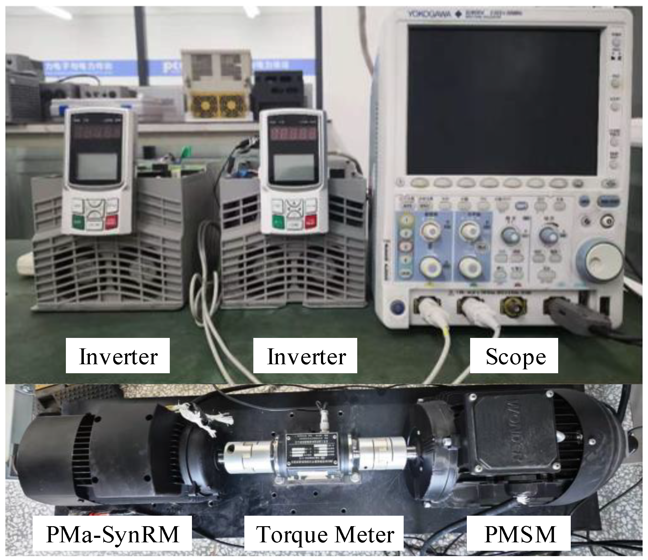
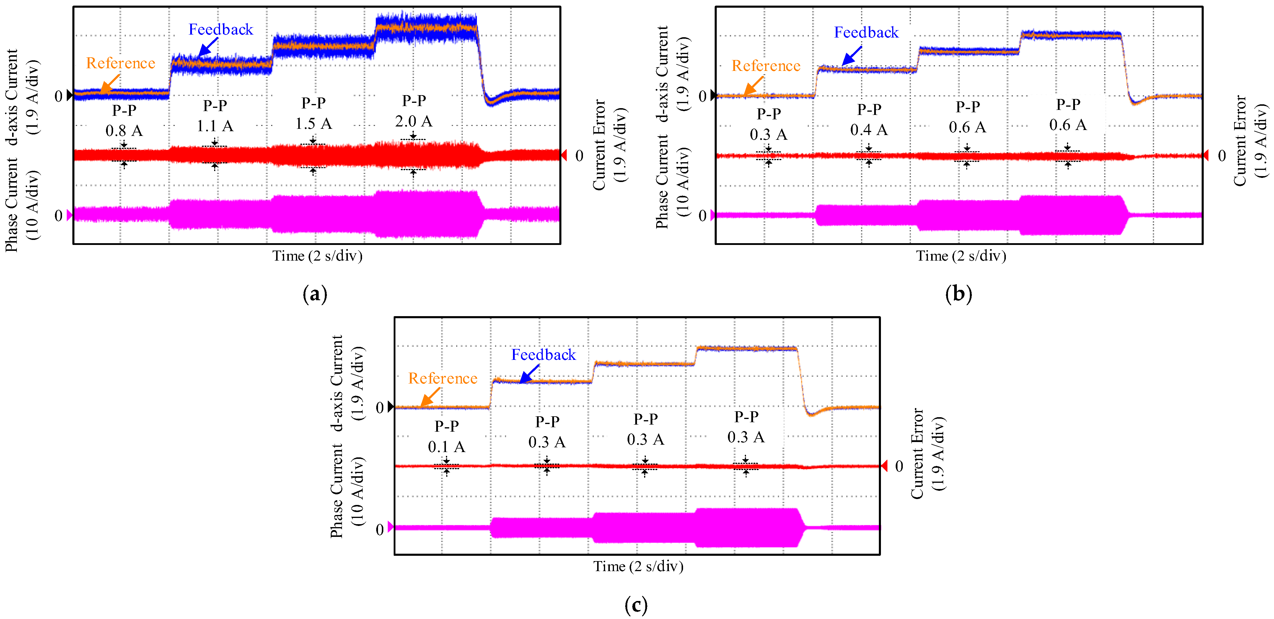
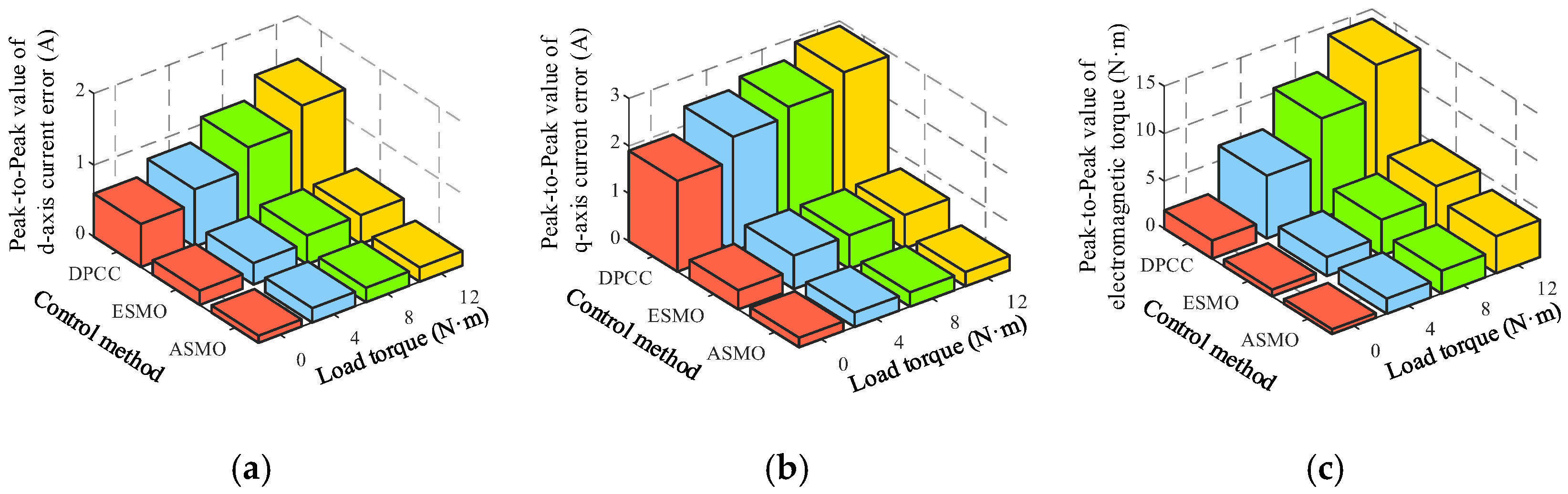
4. Experimental Results and Analysis

Loading tests were conducted on a 2.2 kW permanent magnet-assisted synchronous reluctance motor experimental platform as shown in Figure 8, with its parameters listed in Table 1. The PWM carrier frequency was 6 kHz, and the sliding mode control algorithm was implemented in the ARM STM32F103VCT6 (STMicroelectronics NV, Plan-les-Ouates, Switzerland) chip, with data acquisition performed using a YOKOGAWA DLM2054 (YOKOGAWA, Tokyo, Japan) oscilloscope. The parameters of the proposed method were designed as k1 = λ = 100, gd = gq = 1000, ε = 0.1, δ = 2, a = 0.25, and b = 1.
According to Equation (6), the resistance parameter perturbation has a relatively small impact on current prediction error, and the flux linkage parameter error only affects the d-axis current prediction. Therefore, in the actual experiment, the motor parameter perturbations were set to ΔLd = 0.25, Ld0 = 40 mH, ΔLq = 0.25, and Lq0 = 12 mH, while other parameters remained approximately accurate. The comparative experiments were conducted under these conditions.
The PMa-SynRM operated at no-load condition at 1000 r/min. Starting from 4 s, 30%, 60%, and 90% of the rated load torque were applied sequentially, each lasting for 4 s, after which the load suddenly dropped to zero.
Figure 9 shows the experimental comparison of d-axis currents and errors between traditional deadbeat predictive current control (DPCC), predictive current control based on the exponential sliding mode observer (ESMC), and predictive current control based on the adaptive sliding mode observer (ASMC). Under different load conditions, the peak-to-peak values of d-axis current in Figure 9a are 0.8 A, 1.1 A, 1.5 A, and 2.0 A, respectively; in Figure 9b, they are 0.3 A, 0.4 A, 0.6 A, and 0.6 A, respectively; and in Figure 9c, they are 0.1 A, 0.3 A, 0.3 A, and 0.3 A, respectively. The exponential sliding mode observer achieves an average suppression of 64.8% in d-axis current fluctuation, while the adaptive sliding mode observer achieves an average suppression of 81.5%. The introduction of the adaptive sliding mode reaching law further improves the suppression effect of d-axis current fluctuation.
Figure 10 shows the experimental comparison of q-axis currents and errors between traditional deadbeat predictive current control, predictive current control based on the exponential sliding mode observer, and predictive current control based on the adaptive sliding mode observer. Under different load conditions, the peak-to-peak values of q-axis current in Figure 10a are 2.7 A, 3.4 A, 3.6 A, and 4.1 A, respectively; in Figure 10b, they are 0.6 A, 1.0 A, 1.0 A, and 1.0 A, respectively; and in Figure 10c, they are 0.3 A, 0.4 A, 0.4 A, and 0.4 A, respectively. The exponential sliding mode observer achieves an average suppression of 73.9% in q-axis current fluctuation, while the adaptive sliding mode observer achieves an average suppression of 89.1%. The introduction of the adaptive sliding mode reaching law further improves the suppression effect of q-axis current fluctuation.
Figure 11 shows the experimental comparison of motor speed and electro-magnetic torque between traditional deadbeat predictive current control, predictive current control based on the exponential sliding mode observer, and predictive current control based on the adaptive sliding mode observer. Under different load conditions, the peak-to-peak values of torque in Figure 11a are 1.9 N∙m, 6.6 N∙m, 10.5 N∙m, and 14.0 N∙m, respectively; in Figure 11b, they are 0.7 N∙m, 2.0 N∙m, 3.8 N∙m, and 5.2 N∙m, respectively; and in Figure 11c, they are 0.5 N∙m, 1.6 N∙m, 2.4 N∙m, and 3.9 N∙m, respectively. The exponential sliding mode observer achieves an average suppression of 64.5% in electro-magnetic torque fluctuation, while the adaptive sliding mode observer achieves an average suppression of 74.5%. The introduction of the adaptive sliding mode reaching law further improves the suppression effect of electro-magnetic torque fluctuation. During motor operation, as the load increases, parameter variations become significant, parameter mismatches intensify, and electro-magnetic torque fluctuations increase. ASMO consistently plays a role in suppressing parameter mismatches throughout this process; therefore, the greater the load, the better ASMO’s suppression effect on torque fluctuations. The FFT analysis of the electro-magnetic torque under 30% rated load shows that the exponential sliding mode observer effectively suppresses the main harmonics of torque, while the adaptive sliding mode observer further suppresses harmonics at other frequencies, reducing the total harmonic content and improving the torque performance of the motor.
Figure 12 shows the comparison of compensation voltages between the exponential sliding mode observer and the adaptive sliding mode observer. Under three load conditions, the peak-to-peak values of d- and q-axis compensation voltages in Figure 12a are 23 V and 12 V, respectively, while in Figure 12b, they are 15 V and 10 V, respectively. The adaptive reaching law suppresses the sliding mode chattering, reducing the fluctuation of observer outputs (i.e., the d- and q-axis compensation voltages), thereby decreasing the current and torque fluctuations.
To better test the feasibility of the proposed control scheme in electric vehicle applications, a load reduction experiment was added. The permanent magnet-assisted synchronous reluctance motor was operated at 1000 r/min with no load, and from 4 s onwards, 90%, 60%, and 30% of the rated load torque were applied in segments, with each load duration lasting 4 s, after which the load was reduced to 0. Figure 13 shows the experimental comparison of motor speed and electro-magnetic torque using traditional deadbeat predictive control, predictive control based on the exponential sliding mode observer, and predictive control based on the adaptive sliding mode observer. Under different load conditions, the torque peak-to-peak values in Figure 13a are 16.4 N∙m, 10.0 N∙m, 5.8 N∙m, and 1.4 N∙m, respectively; in Figure 13b, they are 5.3 N∙m, 4.0 N∙m, 2.5 N∙m, and 0.8 N∙m, respectively; and in Figure 13c, they are 4.7 N∙m, 2.2 N∙m, 1.5 N∙m, and 0.5 N∙m, respectively. The exponential sliding mode observer suppresses electro-magnetic torque fluctuations by an average of 62.5%, while the adaptive sliding mode observer suppresses torque fluctuations by an average of 73.8%. In load reduction conditions, ASMO still demonstrates excellent fluctuation suppression performance.
Figure 14 shows a comparison of peak-to-peak values of d-axis and q-axis currents and electro-magnetic torque under different control strategies. The exponential sliding mode observer effectively suppresses the impact of parameter mismatch on deadbeat predictive control, reducing the fluctuations of d-axis and q-axis currents by 64.8% and 73.9%, respectively, and torque fluctuation by 64.5%. The adaptive sliding mode observer, building upon the exponential sliding mode, further improves the control performance of the PMa-SynRM, reducing d-axis and q-axis current fluctuations by 81.5% and 89.1%, respectively, and torque fluctuation by 74.5%, achieving the lowest level of current and torque fluctuations.
As investigated in this paper, in comparison with exponential sliding mode observer (ESMO), ASMO can adjust the approaching speed according to the motor state, thereby improving the motor’s adaptability under various operating conditions. The experimental results demonstrate that ASMO, built upon the foundation of ESMO, improved torque suppression effects by 28.2% and 29.4% under loading and unloading conditions, respectively. Across different operating conditions, it consistently exhibited superior control performance.

5. Conclusions

This paper proposes a deadbeat predictive control strategy based on an adaptive sliding mode observer for PMa-SynRM drives, which can effectively reduce current and torque fluctuations caused by parameter mismatches and sampling delays. The observer tracks voltage disturbances caused by parameter mismatches and compensates for sampled current, effectively suppressing the parameter sensitivity of predictive control and reducing the impact of one-step delay on motor performance. Compared to exponential sliding mode observers, ASMO adjusts parameters according to system states, suppressing the sliding mode chattering phenomenon and effectively improving adaptability. Under different operating conditions, motor current harmonics are reduced by more than 75%, and torque harmonics by more than 70%, achieving the high-performance operation of PMa-SynRM.
Building on this paper, future research will explore the adaptability of this strategy in the field-weakening region under high-speed conditions. Future work should explore the integration of iterative observers and variable-speed sliding mode observers from the literature with ASMO, with the aim of further enhancing fluctuation suppression performance while maintaining manageable computational complexity.

Author Contributions

Conceptualization, B.G., G.Z. and G.W.; methodology, B.G. and G.Z.; software, B.G., G.Z. and D.X.; validation, B.G., G.Z. and G.W.; formal analysis, B.G.; investigation, G.Z.; resources, G.W.; data curation, G.W. and D.X.; writing—original draft, B.G., G.Z. and G.W.; writing—review and editing, G.Z. and G.W.; visualization, B.G.; supervision, B.G.; project administration, G.W. and D.X.; funding acquisition, D.X. All authors have read and agreed to the published version of the manuscript.

Funding

This research was funded by the National Natural Science Foundation of China under Grant 52125701.

Institutional Review Board Statement

Not applicable.

Informed Consent Statement

Not applicable.

Data Availability Statement

The original contributions presented in this study are included in the article. Further inquiries can be directed to the corresponding author.

Conflicts of Interest

The authors declare no conflicts of interest.

Nomenclature

PI Proportional–integral
MPCModel predictive control
DPCCDeadbeat predictive current control
ESMOExponential sliding mode observer
ASMOAdaptive sliding mode observer
ud, uq, id, iqd-axis and q-axis voltages and currents
ΨmNominal values of permanent magnet flux linkage
RNominal values of stator resistance
Ld, LqNominal values of d-axis and q-axis inductances
Ψm0Actual values of permanent magnet flux linkage
R0Actual values of stator resistance
Ld0, Lq0Actual values of d-axis and q-axis inductances
fd, fqd-axis and q-axis parameter disturbances
Fd, FqRates of change in parameter disturbance
Udsmo, UqsmoSliding mode observation functions
gd, gqSliding mode parameters
k1, λExponential reaching rate parameters
MAdaptive factor

References

  1. Wang, K.; Wang, G.; Zhang, G.; Wang, Q.; Li, B.; Xu, D. ESO-Based Robust Hybrid Flux Observer with Active Flux Error Estimation for Position Sensorless PMa-SynRM Drives. IEEE Trans. Transp. Electrif. 2024, in press. [Google Scholar]
  2. Zhang, G.; Xiang, R.; Wang, G.; Li, C.; Bi, G.; Zhao, N.; Xu, D. Hybrid Pseudorandom Signal Injection for Position Sensorless SynRM Drives with Acoustic Noise Reduction. IEEE Trans. Transp. Electrif. 2021, 8, 1313–1325. [Google Scholar] [CrossRef]
  3. Zhang, G.; Li, S.; Li, B.; Wang, Q.; Wang, G.; Xu, D. Acoustic Noise Reduction Using Half-Period-Switching Pseudorandom Sinusoidal Injection with External Tangent Demodulation for Sensorless PMSM Drives. IEEE Trans. Transp. Electrif. 2024, in press. [Google Scholar] [CrossRef]
  4. Jedryczka, C.; Mysinski, M.; Szelag, W. Development and Analysis of Six-Phase Synchronous Reluctance Motor for Increased Fault Tolerance Capabilities. Energies 2024, 17, 2351. [Google Scholar] [CrossRef]
  5. Daryabeigi, E.; Vaez-Zadeh, S. A Combined Control for Fast and Smooth Performance of IPM Motor Drives Over Wide Operating Conditions. IEEE Trans. Energy Convers. 2018, 33, 1384–1391. [Google Scholar] [CrossRef]
  6. Li, Z.; Wang, J.; An, J.; Zhang, Q.; Zhu, Y.; Liu, H.; Sun, H. Control Strategy of Biaxial Variable Gain Cross-Coupled Permanent Magnet Synchronous Linear Motor Based on MPC-MRAS. IEEE Trans. Ind. Appl. 2022, 58, 4733–4743. [Google Scholar] [CrossRef]
  7. Woo, J.-H.; Bang, T.-K.; Lee, H.-K.; Kim, K.-H.; Shin, S.-H.; Choi, J.-Y. Electromagnetic Characteristic Analysis of High-Speed Motors with Rare-Earth and Ferrite Permanent Magnets Considering Current Harmonics. IEEE Trans. Magn. 2020, 57, 1–5. [Google Scholar] [CrossRef]
  8. Rabbi, S.F.; Halloran, M.; LeDrew, T.; Matchem, A.; Rahman, M.A. Modeling and V/F control of a Hysteresis Interior Permanent Magnet Motor. IEEE Trans. Ind. Appl. 2016, 52, 1891–1901. [Google Scholar] [CrossRef]
  9. Rebeiro, R.S.; Uddin, M.N. Performance Analysis of an FLC-Based Online Adaptation of Both Hysteresis and PI Controllers for IPMSM Drive. IEEE Trans. Ind. Appl. 2012, 48, 12–19. [Google Scholar] [CrossRef]
  10. Lee, S.-B. Closed-Loop Estimation of Permanent Magnet Synchronous Motor Parameters by PI Controller Gain Tuning. IEEE Trans. Energy Convers. 2006, 21, 863–870. [Google Scholar] [CrossRef]
  11. Wang, W.; Liu, C.; Liu, S.; Song, Z.; Zhao, H.; Dai, B. Current Harmonic Suppression for Permanent-Magnet Synchronous Motor Based on Chebyshev Filter and PI Controller. IEEE Trans. Magn. 2020, 57, 1–6. [Google Scholar] [CrossRef]
  12. Zhang, Z.; Jing, L.; Wu, X.; Xu, W.; Liu, J.; Lyu, G.; Fan, Z. A Deadbeat PI Controller with Modified Feedforward for PMSM Under Low Carrier Ratio. IEEE Access 2021, 9, 63463–63474. [Google Scholar] [CrossRef]
  13. Sarsembayev, B.; Suleimenov, K.; Do, T.D. High Order Disturbance Observer Based PI-PI Control System with Tracking Anti-Windup Technique for Improvement of Transient Performance of PMSM. IEEE Access 2021, 9, 66323–66334. [Google Scholar] [CrossRef]
  14. Fan, Y.; Chen, J.; Zhang, Q.; Cheng, M. An Improved Inertia Disturbance Suppression Method for PMSM Based on Disturbance Observer and Two-Degree-of-Freedom PI Controller. IEEE Trans. Power Electron. 2022, 38, 3590–3599. [Google Scholar] [CrossRef]
  15. Shen, J.; Wang, X.; Xiao, D.; Wang, Z.; Mao, Y.; He, M. Online Switching Strategy Between Dual Three-Phase PMSM and Open-Winding PMSM. IEEE Trans. Transp. Electrif. 2023, 10, 1519–1529. [Google Scholar] [CrossRef]
  16. Jiang, X.; Wang, Y.; Dong, J. Speed Regulation Method Using Genetic Algorithm for Dual Three-phase Permanent Magnet Synchronous Motors. CES Trans. Electr. Mach. Syst. 2023, 7, 171–178. [Google Scholar] [CrossRef]
  17. Liu, Z.-H.; Nie, J.; Wei, H.-L.; Chen, L.; Li, X.-H.; Lv, M.-Y. Switched PI Control Based MRAS for Sensorless Control of PMSM Drives Using Fuzzy-Logic-Controller. IEEE Open J. Power Electron. 2022, 3, 368–381. [Google Scholar] [CrossRef]
  18. Liu, X.; Yang, H.; Lin, H.; Yu, F.; Yang, Y. A Novel Finite-Set Sliding-Mode Model-Free Predictive Current Control for PMSM Drives Without DC-Link Voltage Sensor. IEEE Trans. Power Electron. 2023, 39, 320–331. [Google Scholar] [CrossRef]
  19. Zhang, X.; Bai, H.; Cheng, M. Improved Model Predictive Current Control with Series Structure for PMSM Drives. IEEE Trans. Ind. Electron. 2021, 69, 12437–12446. [Google Scholar] [CrossRef]
  20. Gao, J.; Gong, C.; Li, W.; Liu, J. Novel Compensation Strategy for Calculation Delay of Finite Control Set Model Predictive Current Control in PMSM. IEEE Trans. Ind. Electron. 2019, 67, 5816–5819. [Google Scholar] [CrossRef]
  21. Gao, F.; Yin, Z.; Li, L.; Li, T.; Liu, J. Gaussian Noise Suppression in Deadbeat Predictive Current Control of Permanent Magnet Synchronous Motors Based on Augmented Fading Kalman Filter. IEEE Trans. Energy Convers. 2022, 38, 1410–1420. [Google Scholar] [CrossRef]
  22. Yao, Y.; Huang, Y.; Peng, F.; Dong, J.; Zhang, H. An Improved Deadbeat Predictive Current Control with Online Parameter Identification for Surface-Mounted PMSMs. IEEE Trans. Ind. Electron. 2019, 67, 10145–10155. [Google Scholar] [CrossRef]
  23. Sun, X.; Tang, Y.; Xiao, X.; Xie, Y. Predictive Trajectory Control Strategy for Permanent Magnet Synchronous Motor Drives Based on Deadbeat Predictive Flux Linkage Control Method. IEEE Trans. Power Electron. 2022, 38, 2327–2338. [Google Scholar] [CrossRef]
  24. Wu, X.; Chen, H.; Liu, B.; Wu, T.; Wang, C.; Huang, S. Improved Deadbeat Predictive Current Control of PMSM Based on a Resistance Adaptive Position Observer. IEEE Trans. Transp. Electrif. 2023, 10, 5215–5224. [Google Scholar] [CrossRef]
  25. Hao, Z.; Yang, Y.; Shao, K.; Liu, Y. Switching Active Disturbance Rejection Based Deadbeat Predictive Current Control for Permanent Magnet Synchronous Motors. IEEE Trans. Power Electron. 2023, 38, 13920–13932. [Google Scholar] [CrossRef]
  26. Wang, X.; Wang, Z.; Xu, Z.; Wang, W.; Wang, B.; Zou, Z.; Chen, J. Deadbeat Predictive Current Control-Based Fault-Tolerant Scheme for Dual Three-Phase PMSM Drives. IEEE J. Emerg. Sel. Top. Power Electron. 2020, 9, 1591–1604. [Google Scholar] [CrossRef]
  27. Jiang, Y.; Xu, W.; Mu, C.; Liu, Y. Improved Deadbeat Predictive Current Control Combined Sliding Mode Strategy for PMSM Drive System. IEEE Trans. Veh. Technol. 2017, 67, 251–263. [Google Scholar] [CrossRef]
  28. Gong, Z.; Zhang, C.; Ba, X.; Guo, Y. Improved Deadbeat Predictive Current Control of Permanent Magnet Synchronous Motor Using a Novel Stator Current and Disturbance Observer. IEEE Access 2021, 9, 142815–142826. [Google Scholar] [CrossRef]
  29. Agoro, S.; Husain, I. Robust Deadbeat Finite-Set Predictive Current Control with Torque Oscillation and Noise Reduction for PMSM Drives. IEEE Trans. Ind. Appl. 2021, 58, 365–374. [Google Scholar] [CrossRef]
  30. Liu, Z.; Huang, X.; Hu, Q.; Li, Z.; Jiang, Z.; Yu, Y.; Chen, Z. A Modified Deadbeat Predictive Current Control for Improving Dynamic Performance of PMSM. IEEE Trans. Power Electron. 2022, 37, 14173–14185. [Google Scholar] [CrossRef]
  31. Wang, Y.; Fang, S.; Huang, D. An Improved Model-Free Active Disturbance Rejection Deadbeat Predictive Current Control Method of PMSM Based on Data-Driven. IEEE Trans. Power Electron. 2023, 38, 9606–9616. [Google Scholar] [CrossRef]
  32. Ba, X.; Wang, P.; Zhang, C.; Zhu, J.G.; Guo, Y. Improved Deadbeat Predictive Current Control to Enhance the Performance of the Drive System of Permanent Magnet Synchronous Motors. IEEE Trans. Appl. Supercond. 2021, 31, 1–4. [Google Scholar] [CrossRef]
  33. Xu, Y.; Li, S.; Zou, J. Integral Sliding Mode Control Based Deadbeat Predictive Current Control for PMSM Drives with Disturbance Rejection. IEEE Trans. Power Electron. 2021, 37, 2845–2856. [Google Scholar] [CrossRef]
  34. Pei, G.; Liu, J.; Gao, X.; Tian, W.; Li, L.; Kennel, R. Deadbeat Predictive Current Control for SPMSM at Low Switching Frequency with Moving Horizon Estimator. IEEE J. Emerg. Sel. Top. Power Electron. 2019, 9, 345–353. [Google Scholar] [CrossRef]
  35. Zhang, X.; Wang, Z.; Bai, H. Sliding-Mode-Based Deadbeat Predictive Current Control for PMSM Drives. IEEE J. Emerg. Sel. Top. Power Electron. 2022, 11, 962–969. [Google Scholar] [CrossRef]
  36. Lei, J.; Fang, S.; Huang, D.; Wang, Y. Enhanced Deadbeat Predictive Current Control for PMSM Drives Using Iterative Sliding Mode Observer. IEEE Trans. Power Electron. 2023, 38, 13866–13876. [Google Scholar] [CrossRef]
Figure 1. Block diagram of conventional DPCC.
Wevj 16 00202 g001
Figure 2. Relationship between parameter mismatch and d-axis current prediction error. (a) d-axis and q-axis inductance mismatch. (b) Resistance and flux linkage mismatch.
Wevj 16 00202 g002
Figure 3. Relationship between parameter mismatch and q-axis current prediction error. (a) d-axis and q-axis inductance mismatch. (b) Resistance and flux linkage mismatch.
Wevj 16 00202 g003
Figure 4. Schematic diagram of DPCC with adaptive sliding mode observer.
Wevj 16 00202 g004
Figure 5. Relationship between adaptive reaching law and error. (a) Error and uniform velocity term. (b) Error and exponential term.
Wevj 16 00202 g005
Figure 6. Discrete system block diagram of d-axis current observer.
Wevj 16 00202 g006
Figure 7. Discrete system block diagram of q-axis current observer.
Wevj 16 00202 g007
Figure 8. PMa-SynRM experimental platform.
Wevj 16 00202 g008
Figure 9. Experimental comparison of d-axis current and its error. (a) Conventional DPCC. (b) With exponential sliding mode observer. (c) With adaptive sliding mode observer.
Wevj 16 00202 g009
Figure 10. Experimental comparison of q-axis current and its error. (a) Conventional DPCC. (b) With exponential sliding mode observer. (c) With adaptive sliding mode observer.
Wevj 16 00202 g010
Figure 11. Experimental comparison of motor speed and electro-magnetic torque. (a) Conventional DPCC. (b) With exponential sliding mode observer. (c) With adaptive sliding mode observer. (d) FFT analysis of electro-magnetic torque.
Wevj 16 00202 g011
Figure 12. Experimental comparison of d-axis and q-axis compensation voltage. (a) Exponential sliding mode observer. (b) Adaptive sliding mode observer.
Wevj 16 00202 g012
Figure 13. Experimental comparison of motor speed and electro-magnetic torque (load reduction). (a) Conventional DPCC. (b) With exponential sliding mode observer. (c) With adaptive sliding mode observer.
Wevj 16 00202 g013
Figure 14. Comparison of motor performance under different control methods. (a) Peak-to-peak value of d-axis current error. (b) Peak-to-peak value of q-axis current error. (c) Peak-to-peak value of electro-magnetic torque error.
Wevj 16 00202 g014
Table 1. Parameters of PMa-SynRM.
ParameterValueParameterValue
Rated power (kW)2.2Pole pairs3
Rated current (A)4.8Stator resistance (Ω)3.0
Rated speed (r/min)1500D-axis inductance (mH)154
Flux linkage (Wb)0.21Q-axis inductance (mH)45
Disclaimer/Publisher’s Note: The statements, opinions and data contained in all publications are solely those of the individual author(s) and contributor(s) and not of MDPI and/or the editor(s). MDPI and/or the editor(s) disclaim responsibility for any injury to people or property resulting from any ideas, methods, instructions or products referred to in the content.

