


An Optimal Multi-Zone Fast-Charging System Architecture for MW-Scale EV Charging Sites


Abstract
1. Introduction
2. Evolution of EVFS Architectures in the Literature
3. Architecture of Existing EVFSs with High-Power Fast Chargers
4. Requirements of a Modern MW-Scale EVFS
4.1. Requirements at the EV-Charging Side
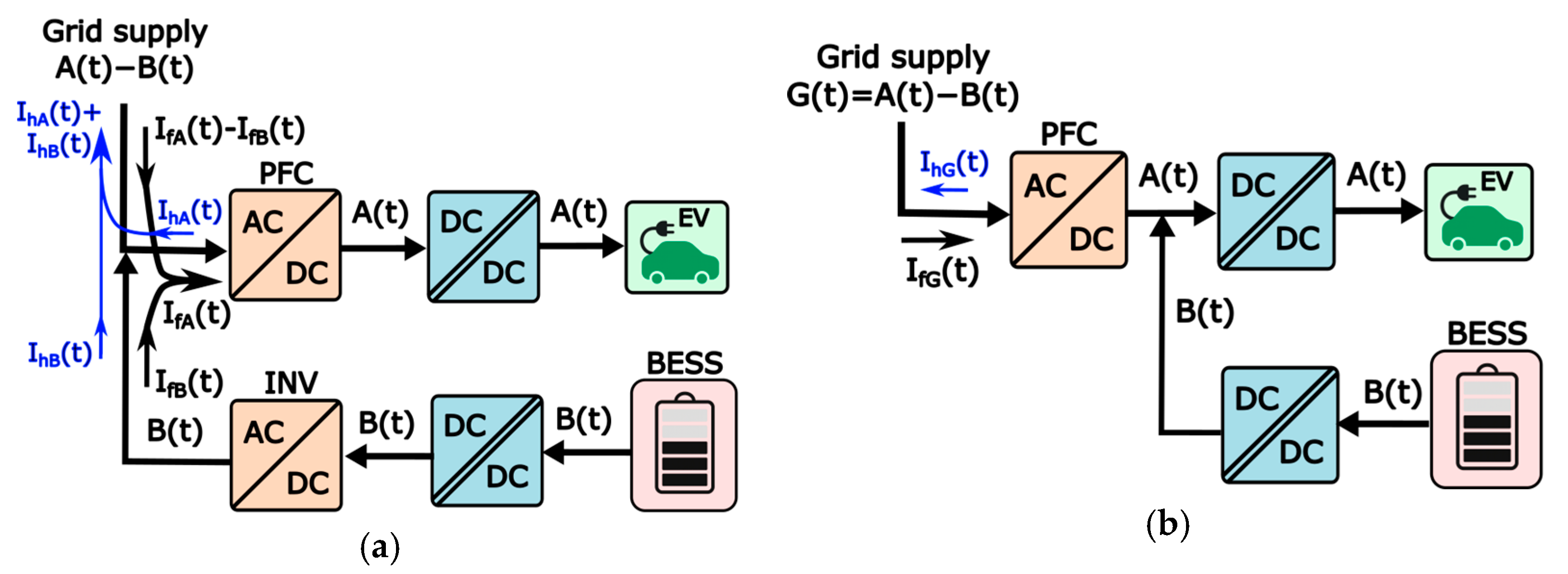
4.2. Requirements for BESS Integration
5. Proposed Architecture for a MW-Scale EVFS
5.1. Choice of Grid Isolation and AC-DC Stages for the Proposed EVFS Architecture
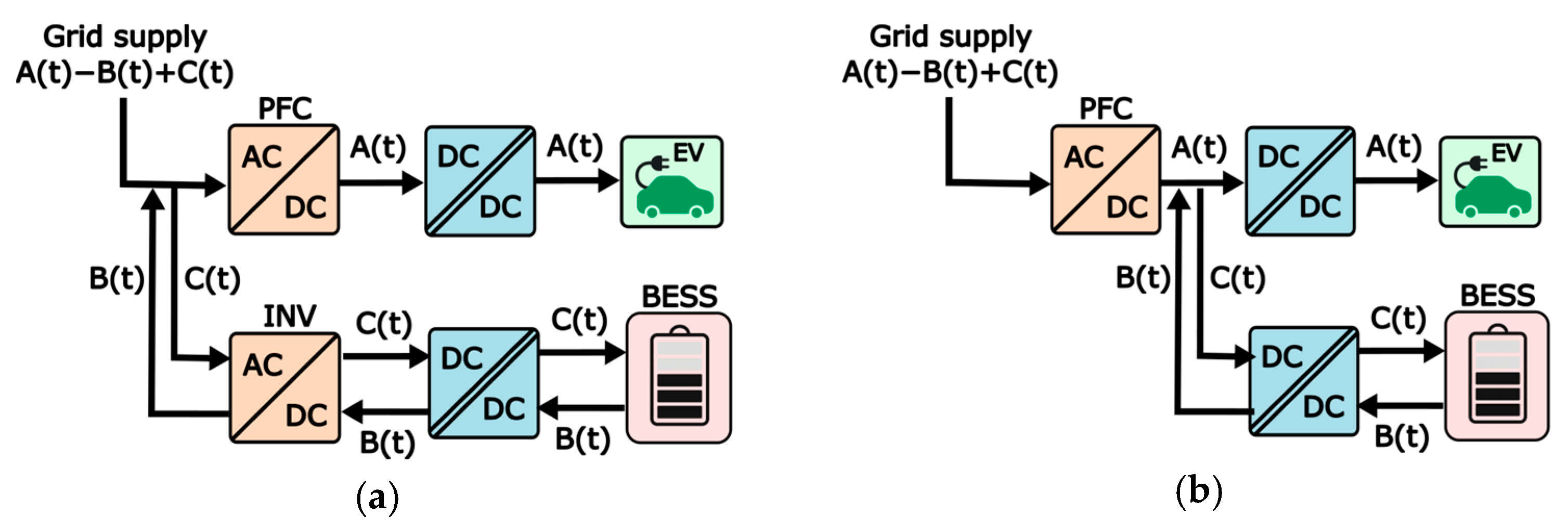
5.2. Choice of Optimal Topologies for the DC-DC Stages of the Proposed EVFS Architecture
5.3. Choice of Voltage Levels for Common DC-Bus and DC-DC Stages of the Proposed EVFS
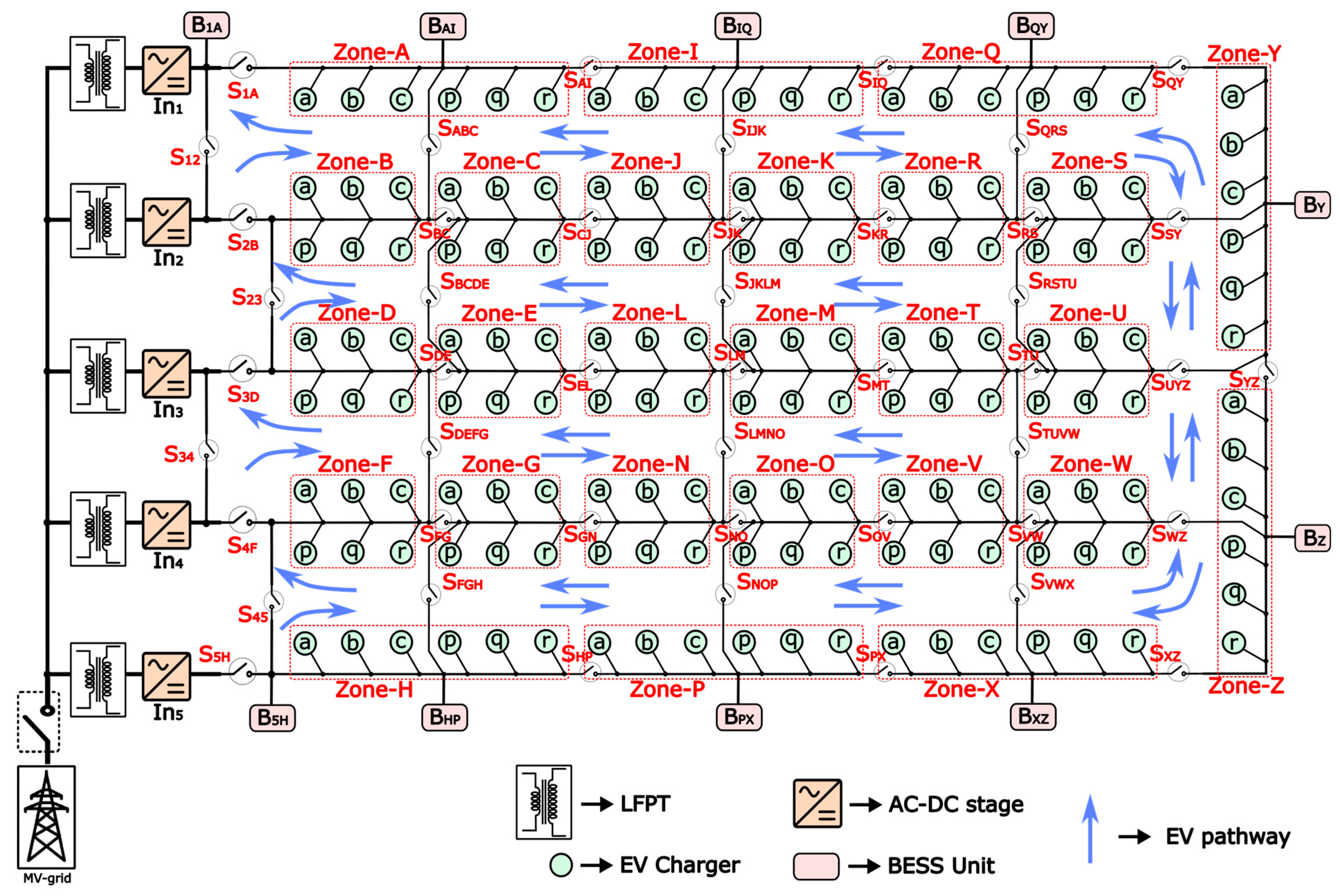
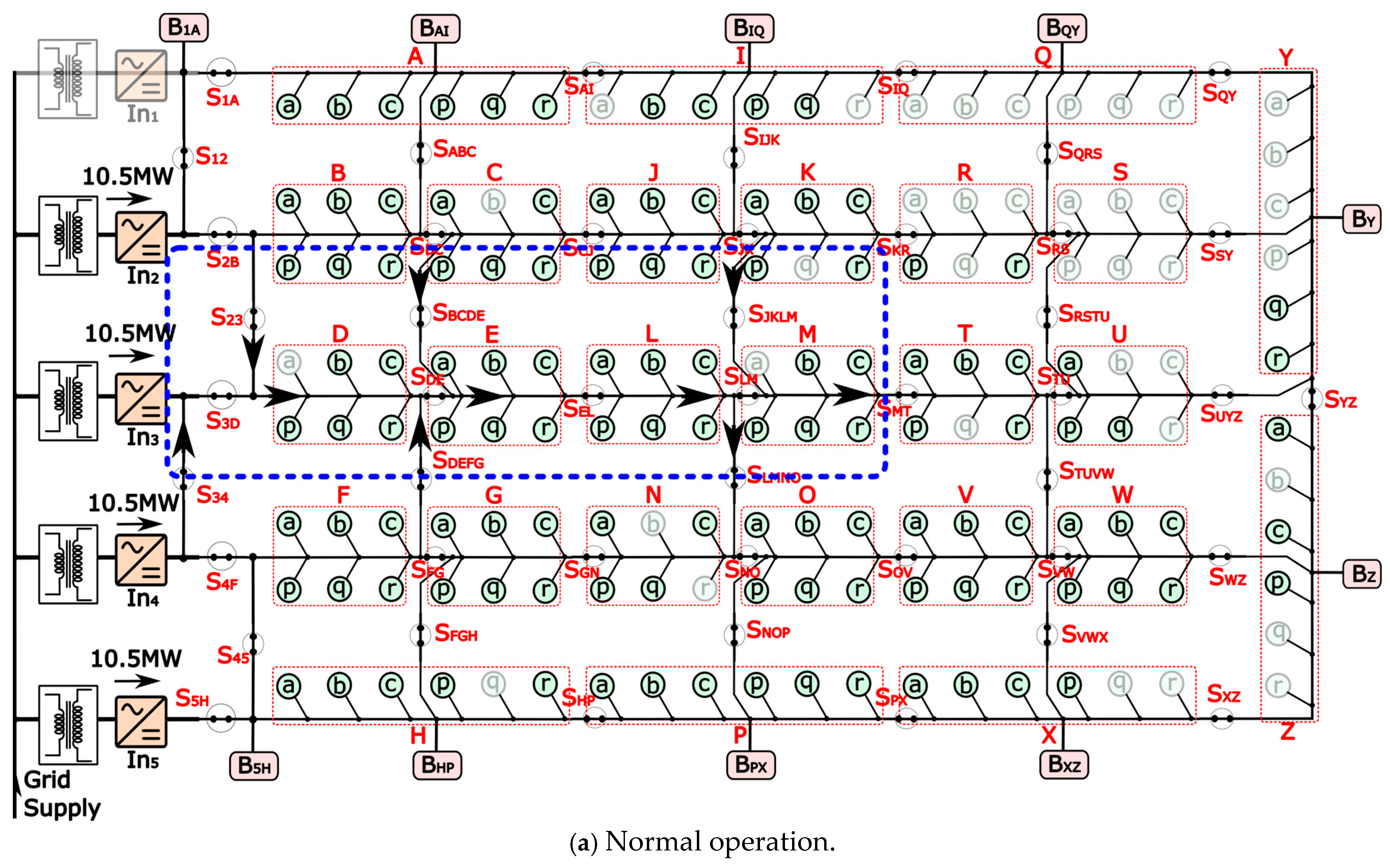
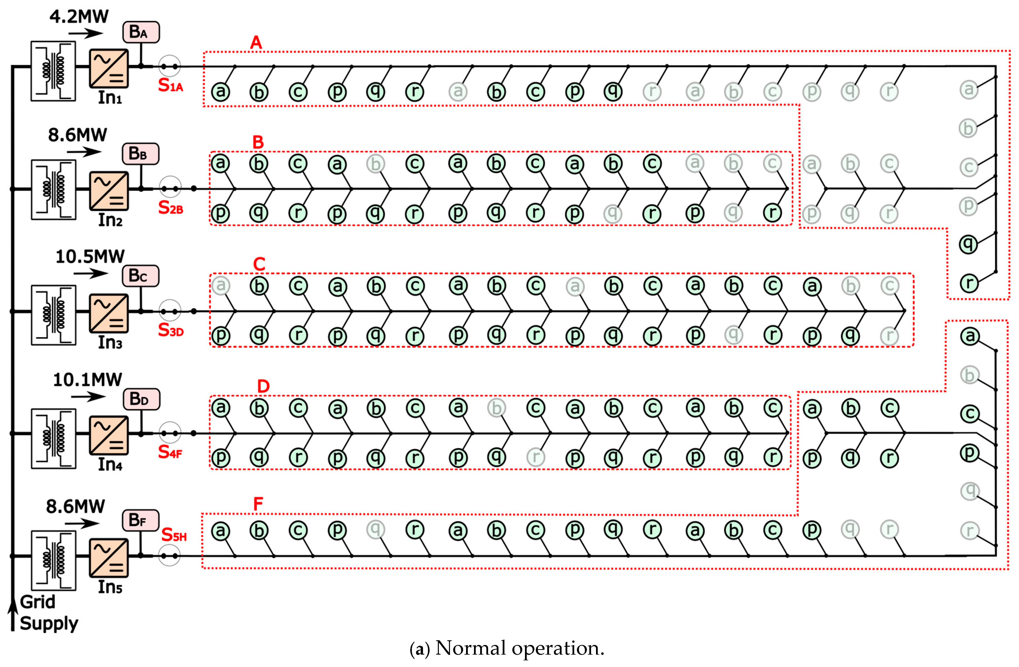
5.4. Scaled-Up EVFS Layout with 156 EV Chargers
6. Evaluation of the Proposed Multi-Zone EVFS Architecture
6.1. Structural Comparison of the Proposed EVFS Architecture
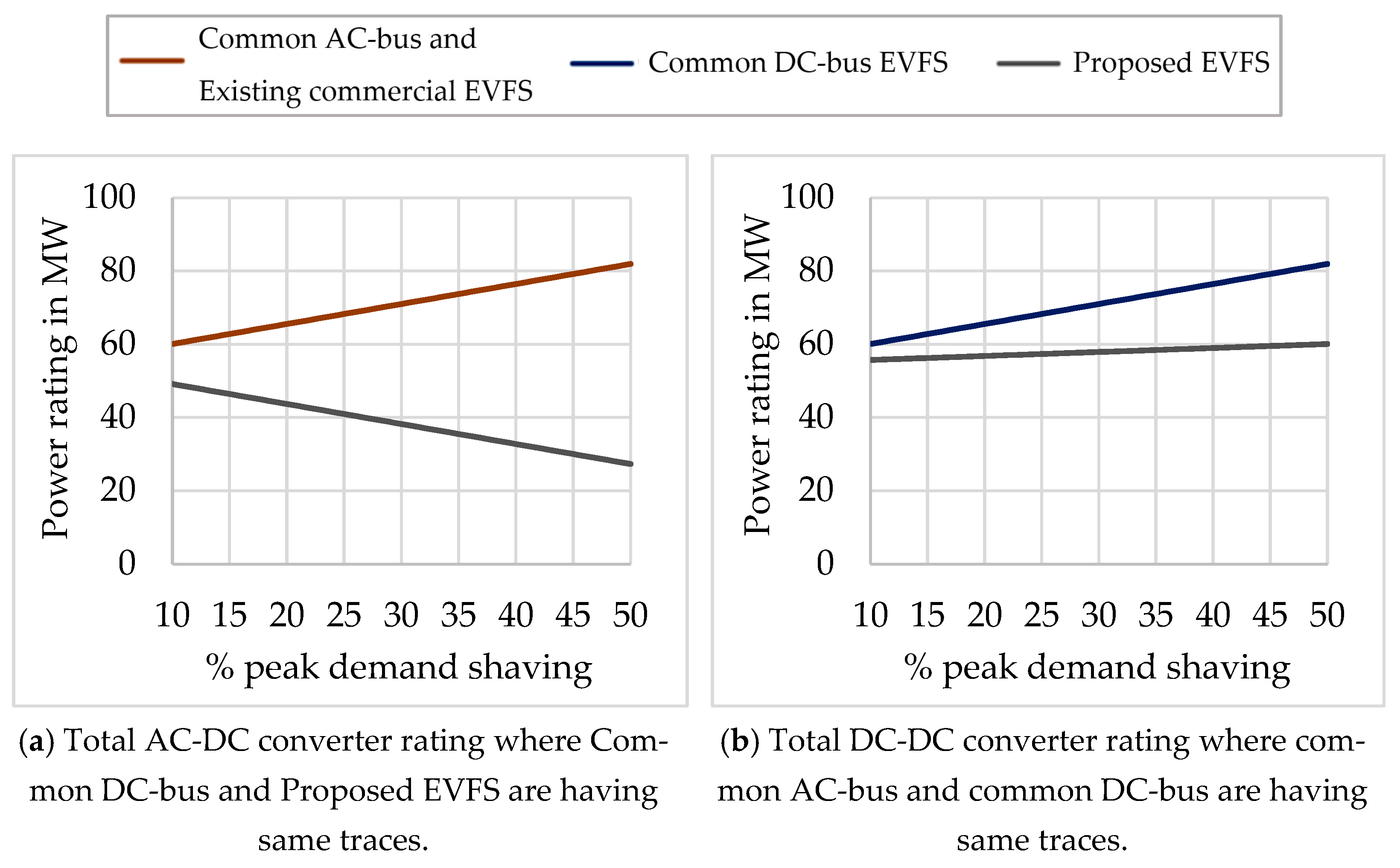
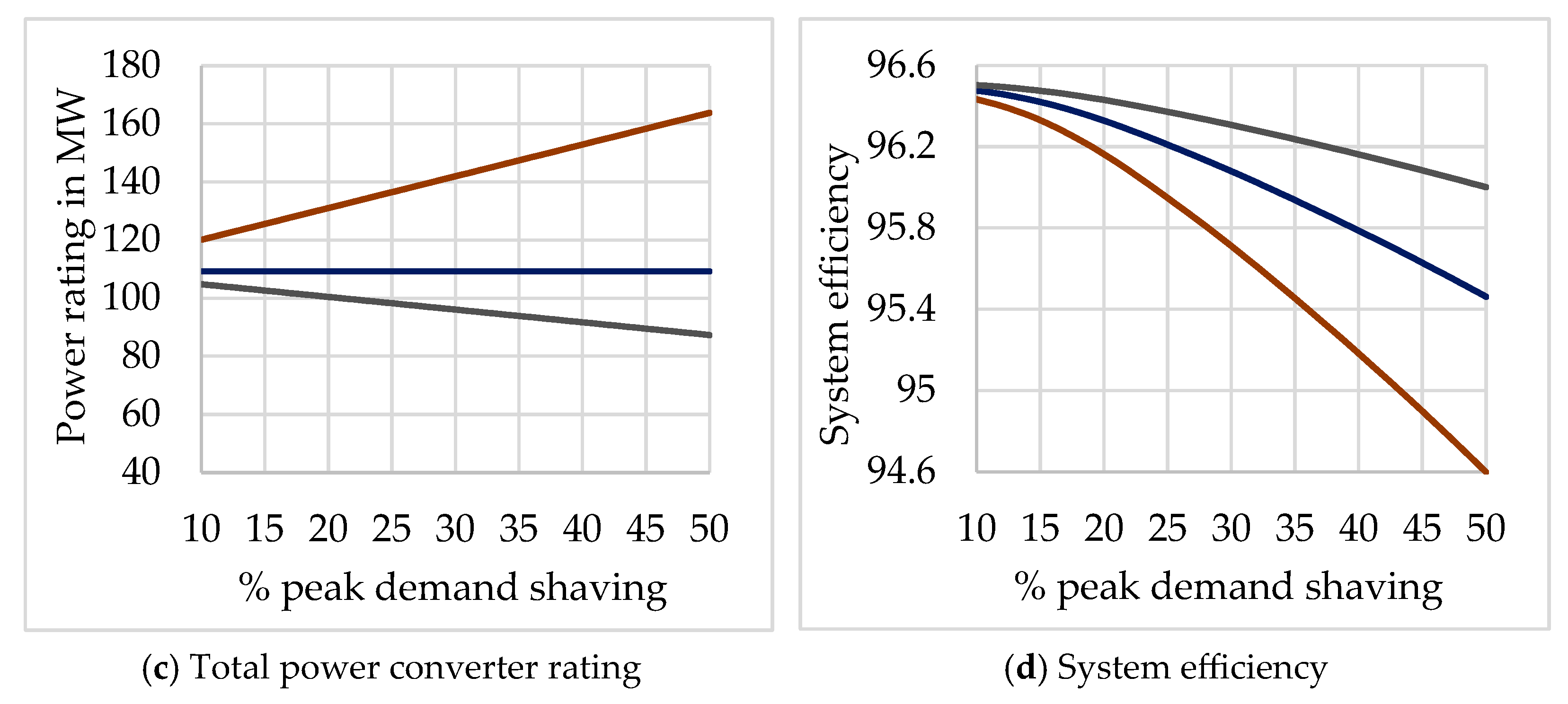
6.2. Comparison of the System Efficiency and Converter Ratings of the Proposed EVFS Architecture
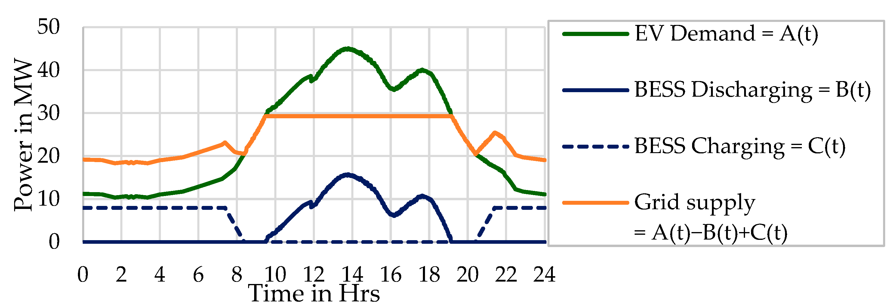
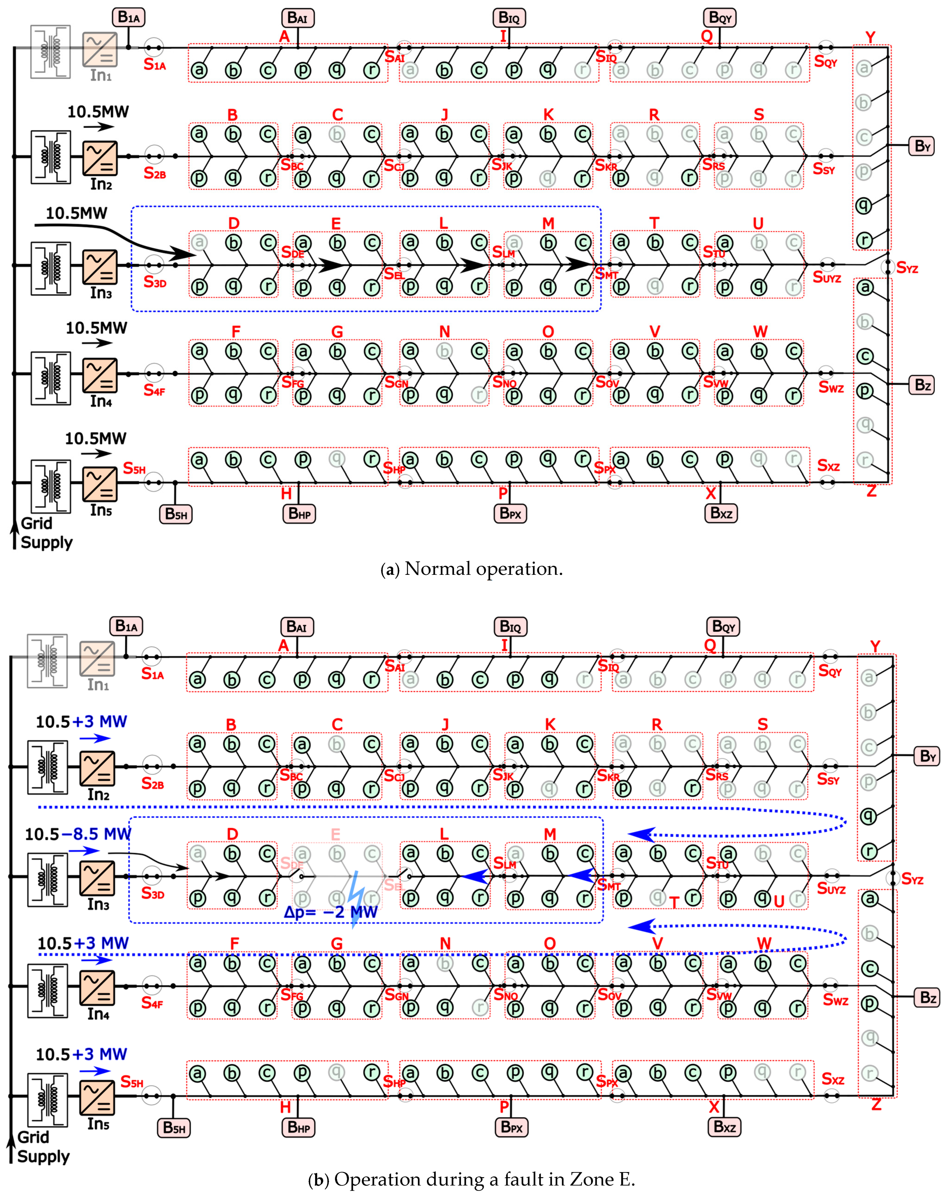
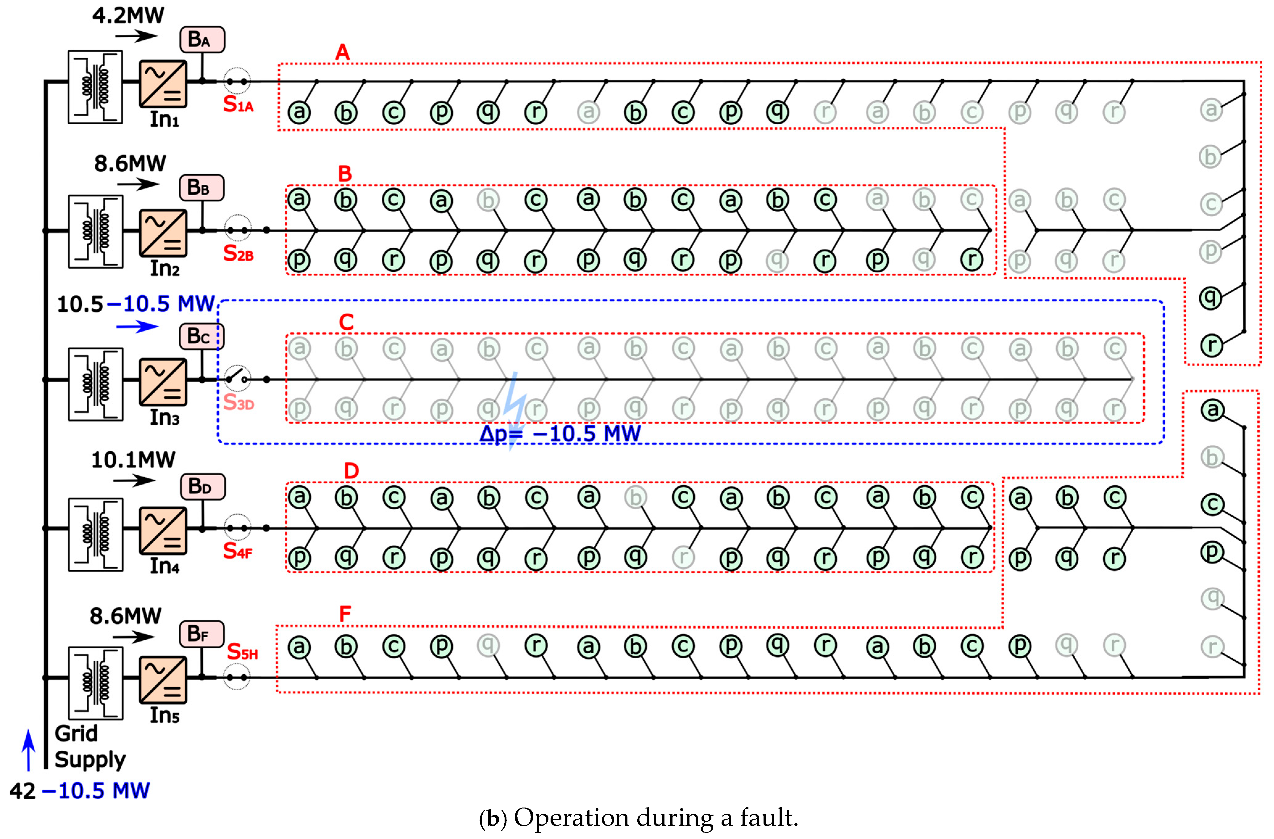
6.3. Evaluation of the Multi-Zonal Operation of the Proposed EVFS Architecture
6.4. Grid Impacts of the Proposed Multi-Zone EVFS Architecture
7. Conclusions
Author Contributions
Funding
Data Availability Statement
Conflicts of Interest
References
- Available online: https://afdc.energy.gov/fuels/electricity-infrastructure-trends (accessed on 6 April 2025).
- Available online: https://insideevs.com/news/717202/tesla-supercharging-network-deployment-2024q1/ (accessed on 6 April 2025).
- Available online: https://media.electrifyamerica.com/releases/244 (accessed on 6 April 2025).
- Available online: https://economictimes.indiatimes.com/industry/renewables/500-km-range-after-15-minutes-charging-this-new-tech-may-revolutionise-ev-sector/articleshow/106014324.cms?from=mdr (accessed on 6 April 2025).
- Available online: https://www.byd.com/mea/news-list/byd-unveils-super-e-platform-with-megawatt-flash-charging (accessed on 6 April 2025).
- Available online: https://www.fox13seattle.com/news/largest-ev-charging-mount-vernon (accessed on 6 April 2025).
- Available online: https://evchargingstations.com/chargingnews/tesla-announces-a-massive-168-stall-supercharging-oasis/ (accessed on 6 April 2025).
- The EV Transition Explained: Charger Infrastructure—IEEE Spectrum. Available online: https://spectrum.ieee.org/the-ev-transition-explained-2658463735 (accessed on 6 April 2025).
- Bai, S.; Yu, D.; Lukic, S. Optimum design of an EV/PHEV charging station with DC bus and storage system. In Proceedings of the IEEE Energy Conversion Congress and Exposition, Atlanta, GA, USA, 12–16 September 2010; pp. 1178–1184. [Google Scholar]
- Srdic, S.; Lukic, S. Toward Extreme Fast Charging: Challenges and Opportunities in Directly Connecting to Medium-Voltage Line. IEEE Electrif. Mag. 2019, 7, 22–31. [Google Scholar] [CrossRef]
- Iyer, V.M.; Gulur, S.; Gohil, G.; Bhattacharya, S. An Approach Towards Extreme Fast Charging Station Power Delivery for Electric Vehicles with Partial Power Processing. IEEE Trans. Ind. Electron. 2020, 67, 8076–8087. [Google Scholar] [CrossRef]
- Hoffmann, F.; Person, J.; Andresen, M.; Liserre, M.; Freijedo, F.D.; Wijekoon, T. A Multiport Partial Power Processing Converter With Energy Storage Integration for EV Stationary Charging. IEEE J. Emerg. Sel. Top. Power Electron. 2022, 10, 7950–7962. [Google Scholar] [CrossRef]
- Chandra Mouli, G.R.; Schijffelen, J.; van den Heuvel, M.; Kardolus, M.; Bauer, P. A 10 kW Solar-Powered Bidirectional EV Charger Compatible With Chademo and COMBO. IEEE Trans. Power Electron. 2019, 34, 1082–1098. [Google Scholar] [CrossRef]
- Kolar, J.W.; Ortiz, G. Solid-state-transformers: Key components of future traction and smart grid systems. In Proceedings of the International Power Electronics Conference-ECCE Asia (IPEC 2014), Hiroshima, Japan, 18–21 May 2014; pp. 18–21. [Google Scholar]
- Nair, A.C.; Fernandes, B.G. Solid-State Transformer Based Fast Charging Station for Various Categories of Electric Vehicles with Batteries of Vastly Different Ratings. IEEE Trans. Ind. Electron. 2021, 68, 10400–10411. [Google Scholar] [CrossRef]
- Bahrami, A.; Narimani, M. A New Medium-Voltage Architecture for Ultra-Fast Electric Vehicle (EV) Charging Stations. In Proceedings of the 2023 IEEE Applied Power Electronics Conference and Exposition (APEC), Orlando, FL, USA; 2023; pp. 3111–3118. [Google Scholar] [CrossRef]
- Ferreira Costa, L.; De Carne, G.; Buticchi, G.; Liserre, M. The Smart Transformer: A solid-state transformer tailored to provide ancillary services to the distribution grid. IEEE Power Electron. Mag. 2017, 4, 56–67. [Google Scholar] [CrossRef]
- De Seram, R.; Golder, A.; Williamson, S.S. Recent Advancements in Solid State Transformer-based EV Fast Charging Stations. In Proceedings of the 2023 IEEE 14th International Conference on Power Electronics and Drive Systems (PEDS), Montreal, QC, Canada, 7–10 August 2023; pp. 1–6. [Google Scholar] [CrossRef]
- Starke, M.; Moorthy, R.S.K.; Adib, A.; Dean, B.; Chinthavali, M.; Xiao, B.; Campbell, S. A MW scale charging architecture for supporting extreme fast charging of heavy-duty electric vehicles. In Proceedings of the 2022 IEEE Transportation Electrification Conference & Expo (ITEC), Anaheim, CA, USA, 15–17 June 2022; pp. 485–490. [Google Scholar] [CrossRef]
- Vasiladiotis, M.; Rufer, A. A Modular Multiport Power Electronic Transformer with Integrated Split Battery Energy Storage for Versatile Ultrafast EV Charging Stations. IEEE Trans. Ind. Electron. 2015, 62, 3213–3222. [Google Scholar] [CrossRef]
- Rivera, S.; Wu, B.; Kouro, S.; Yaramasu, V.; Wang, J. Electric Vehicle Charging Station Using a Neutral Point Clamped Converter with Bipolar DC Bus. IEEE Trans. Ind. Electron. 2015, 62, 1999–2009. [Google Scholar] [CrossRef]
- Tan, L.; Wu, B.; Yaramasu, V.; Rivera, S.; Guo, X. Effective Voltage Balance Control for Bipolar-DC-Bus-Fed EV Charging Station with Three-Level DC–DC Fast Charger. IEEE Trans. Ind. Electron. 2016, 63, 4031–4041. [Google Scholar] [CrossRef]
- Rivera, S.; Wu, B. Electric Vehicle Charging Station with an Energy Storage Stage for Split-DC Bus Voltage Balancing. IEEE Trans. Power Electron. 2017, 32, 2376–2386. [Google Scholar] [CrossRef]
- Pires, V.F.; Cordeiro, A.; Roncero-Clemente, C.; Rivera, S.; Dragičević, T. DC–DC Converters for Bipolar Microgrid Voltage Balancing: A Comprehensive Review of Architectures and Topologies. IEEE J. Emerg. Sel. Top. Power Electron. 2023, 11, 981–998. [Google Scholar] [CrossRef]
- Available online: https://teslamotorsclub.com/tmc/threads/supercharger-mountain-view-ca-1049-el-monte-ave-live-12-jul-2024-12-v4-stalls.323153/ (accessed on 6 April 2025).
- Available online: https://evchargingstations.com/chargingnews/tesla-v4-supercharger-cabinet-specs/ (accessed on 6 April 2025).
- Rivera, S.; Kouro, S.; Vazquez, S.; Goetz, S.M.; Lizana, R.; Romero-Cadaval, E. Electric Vehicle Charging Infrastructure: From Grid to Battery. IEEE Ind. Electron. Mag. 2021, 15, 37–51. [Google Scholar] [CrossRef]
- Available online: https://www.tesla.com/megapack/design (accessed on 6 April 2025).
- Available online: https://www.teslarati.com/how-many-evs-sold-us-2024-model/ (accessed on 6 April 2025).
- Available online: https://electrek.co/2025/01/14/top-10-best-selling-evs-us-2024/ (accessed on 6 April 2025).
- Available online: https://www.caranddriver.com/news/g29994375/future-electric-cars-trucks/ (accessed on 6 April 2025).
- Available online: https://cars.usnews.com/cars-trucks/advice/future-electric-cars?slide=2 (accessed on 6 April 2025).
- Available online: https://ev.com/news/tesla-rolls-out-megapackchargers-to-ease-holiday-ev-charging-surge (accessed on 6 April 2025).
- Negarestani, S.; Fotuhi-Firuzabad, M.; Rastegar, M.; Rajabi-Ghahnavieh, A. Optimal Sizing of Storage System in a Fast Charging Station for Plug-in Hybrid Electric Vehicles. IEEE Trans. Transp. Electrif. 2016, 2, 443–453. [Google Scholar] [CrossRef]
- Hussain, A.; Bui, V.-H.; Kim, H.-M. Optimal Sizing of Battery Energy Storage System in a Fast EV Charging Station Considering Power Outages. IEEE Trans. Transp. Electrif. 2020, 6, 453–463. [Google Scholar] [CrossRef]
- Li, J.; He, S.; Yang, Q.; Ma, T.; Wei, Z. Optimal Design of the EV Charging Station with Retired Battery Systems Against Charging Demand Uncertainty. IEEE Trans. Ind. Inform. 2023, 19, 3262–3273. [Google Scholar] [CrossRef]
- Theodore, A.M.; Şahin, M.E. Modeling and simulation of a series and parallel battery pack model in MATLAB/Simulink. Turk. J. Electr. Power Energy Syst. 2024, 4, 2–12. [Google Scholar]
- Available online: https://www.ti.com/lit/an/slla497/slla497.pdf?ts=1751325947763 (accessed on 6 April 2025).
- Available online: https://www.ti.com/content/dam/videos/external-videos/en-us/3/3816841626001/5785710439001.mp4/subassets/deep_dive_on_sic-based_10kw_grid_tie_inverter_design_challenges.pdf (accessed on 6 April 2025).
- Available online: https://www.ti.com/lit/ug/tidue53j/tidue53j.pdf?ts=1751264681031 (accessed on 6 April 2025).
- Available online: https://www.ti.com/lit/ug/tiduf18a/tiduf18a.pdf (accessed on 6 April 2025).
- Zientarski, J.R.R.; Martins, M.L.d.S.; Pinheiro, J.R.; Hey, H.L. Series-Connected Partial-Power Converters Applied to PV Systems: A Design Approach Based on Step-Up/Down Voltage Regulation Range. IEEE Trans. Power Electron. 2018, 33, 7622–7633. [Google Scholar] [CrossRef]
- Rehlaender, P.; Schafmeister, F.; Böcker, J. Interleaved Single-Stage LLC Converter Design Utilizing Half- and Full-Bridge Configurations for Wide Voltage Transfer Ratio Applications. IEEE Trans. Power Electron. 2021, 36, 10065–10080. [Google Scholar] [CrossRef]
- Xue, B.; Wang, H.; Liang, J.; Cao, Q.; Li, Z. Phase-Shift Modulated Interleaved LLC Converter With Ultrawide Output Voltage Range. IEEE Trans. Power Electron. 2021, 36, 493–503. [Google Scholar] [CrossRef]
- Elezab, A.; Zayed, O.; Abuelnaga, A.; Narimani, M. High Efficiency LLC Resonant Converter With Wide Output Range of 200–1000 V for DC-Connected EVs Ultra-Fast Charging Stations. IEEE Access 2023, 11, 33037–33048. [Google Scholar] [CrossRef]
- Li, Z.; Xue, B.; Wang, H. An Interleaved Secondary-Side Modulated LLC Resonant Converter for Wide Output Range Applications. IEEE Trans. Ind. Electron. 2020, 67, 1124–1135. [Google Scholar] [CrossRef]
- Althurthi, S.B.; Rajashekara, K.; Debnath, T. A Novel Ultrawide Output Range DC–DC Converter for EV Fast Charging. IEEE J. Emerg. Sel. Top. Ind. Electron. 2024, 5, 586–596. [Google Scholar] [CrossRef]
- Lyu, D.; Soeiro, T.B.; Bauer, P. Design and Implementation of a Reconfigurable Phase Shift Full-Bridge Converter for Wide Voltage Range EV Charging Application. IEEE Trans. Transp. Electrif. 2023, 9, 1200–1214. [Google Scholar] [CrossRef]
- Zayed, O.; Elezab, A.; Abuelnaga, A.; Narimani, M. A Dual-Active Bridge Converter With a Wide Output Voltage Range (200–1000 V) for Ultrafast DC-Connected EV Charging Stations. IEEE Trans. Transp. Electrif. 2023, 9, 3731–3741. [Google Scholar] [CrossRef]
- Texas Instruments Design Guide: TIDM-02002, Bidirectional CLLLC Resonant Dual Active Bridge (DAB) Reference Design for HEV/EV Onboard Charger, TIDM-02002 Reference Design. [Online]. March 2019. Available online: https://www.ti.com/lit/pdf/tidt094 (accessed on 6 April 2025).
- Infineon Technologies Design Guide: UG 2020-31, 11 kW Bi-Directional CLLC DC-DC Converter with 1200 V and 1700 V CoolSiC™ MOSFET. [Online]. Available online: https://www.infineon.com/dgdl/Infineon-UG-2020-31_REF_DAB11KIZSICSYS-UserManual-v01_01-EN.pdf?fileId=5546d46276fb756a0177060f64a829de (accessed on 6 April 2025).
- dos Santos, N.G.F.; Zientarski, J.R.R.; Martins, M.L.d.S. A Review of Series-Connected Partial Power Converters for DC–DC Applications. IEEE J. Emerg. Sel. Top. Power Electron. 2022, 10, 7825–7838. [Google Scholar] [CrossRef]
- Anzola, J.; Aizpuru, I.; Romero, A.A.; Loiti, A.A.; Lopez-Erauskin, R.; Artal-Sevil, J.S.; Bernal, C. Review of Architectures Based on Partial Power Processing for DC-DC Applications. IEEE Access 2020, 8, 103405–103418. [Google Scholar] [CrossRef]
- Rivera, S.; Rojas, J.; Kouro, S.; Lehn, P.W.; Lizana, R.; Renaudineau, H.; Dragičević, T. Partial-Power Converter Topology of Type II for Efficient Electric Vehicle Fast Charging. IEEE J. Emerg. Sel. Top. Power Electron. 2022, 10, 7839–7848. [Google Scholar] [CrossRef]
- Iyer, V.M.; Gulur, S.; Bhattacharya, S.; Ramabhadran, R. A partial power converter interface for battery energy storage integration with a DC microgrid. In Proceedings of the 2019 IEEE Energy Conversion Congress and Exposition (ECCE), Baltimore, MD, USA, 29 September–3 October 2019; pp. 5783–5790. [Google Scholar]
- Rivera, S.; Flores-Bahamonde, F.; Renaudineau, H.; Dragicevic, T.; Kouro, S. A Buck-Boost Series Partial Power Converter using a Three-Port Structure for Electric Vehicle Charging Stations. In Proceedings of the 2021 IEEE 12th Energy Conversion Congress & Exposition—Asia (ECCE-Asia), Singapore, 24–27 May 2021; pp. 1749–1754. [Google Scholar] [CrossRef]
- Althurthi, S.B.; Rajashekara, K.; Rathore, V. A Dual Power Path DC-DC Step Up/Down Partial Power Converter for Electric Vehicle Fast Charging. In Proceedings of the 2023 IEEE Energy Conversion Congress and Exposition (ECCE), Nashville, TN, USA, 29 October–2 November 2023; pp. 6365–6370. [Google Scholar] [CrossRef]
- Muñoz, R.V.; Renaudineau, H.; Rivera, S.; Kouro, S. Evaluation of DC-DC buck-boost partial power converters for EV fast charging application. In Proceedings of the IECON 2021—47th Annual Conference of the IEEE Industrial Electronics Society, Toronto, ON, Canada, 13–16 October 2021; pp. 1–6. [Google Scholar] [CrossRef]


| Ref. | Common Bus Type | Grid-Side Isolation | EV–EV Isolation | BESS Integration | Description |
|---|---|---|---|---|---|
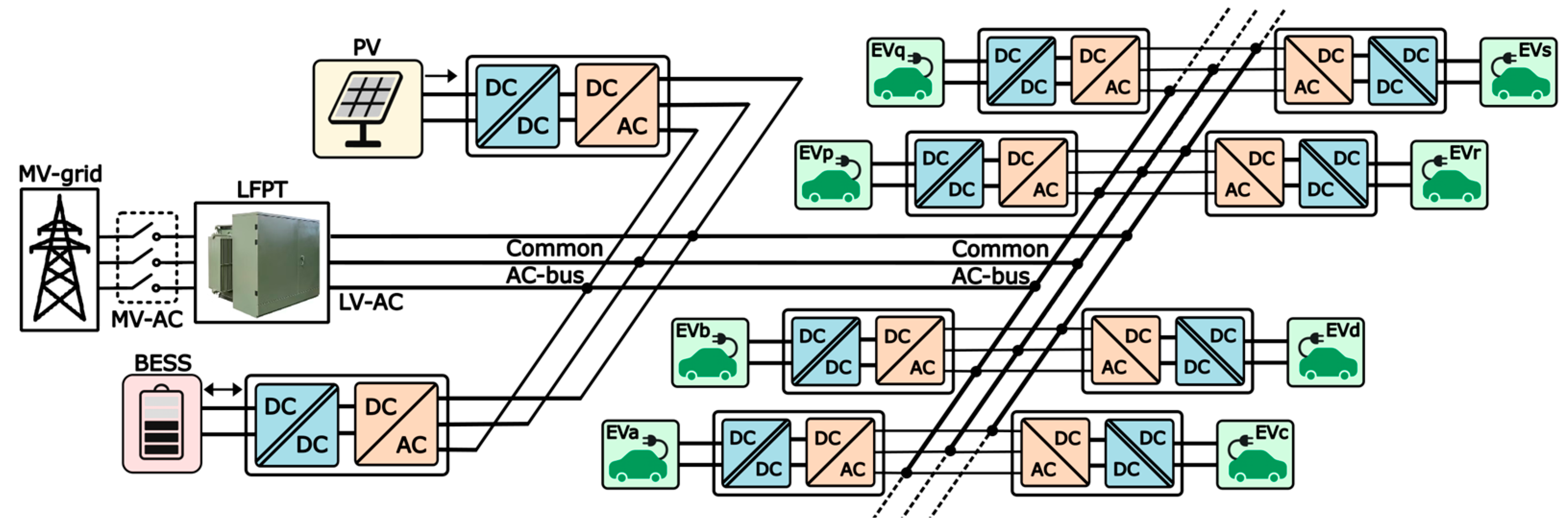
| - | LV-AC | LFPT | Isolated DC-DC at EV side | AC-DC + DC-DC stages | Multiple power converter stages, bulky, and more system losses. |
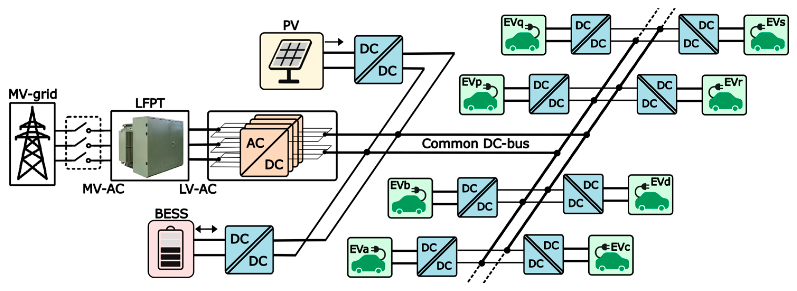
| [9] | LV-DC | LFPT | Isolated DC-DC at EV side | Isolated DC-DC stage | Fewer power conversion units and efficient system. |
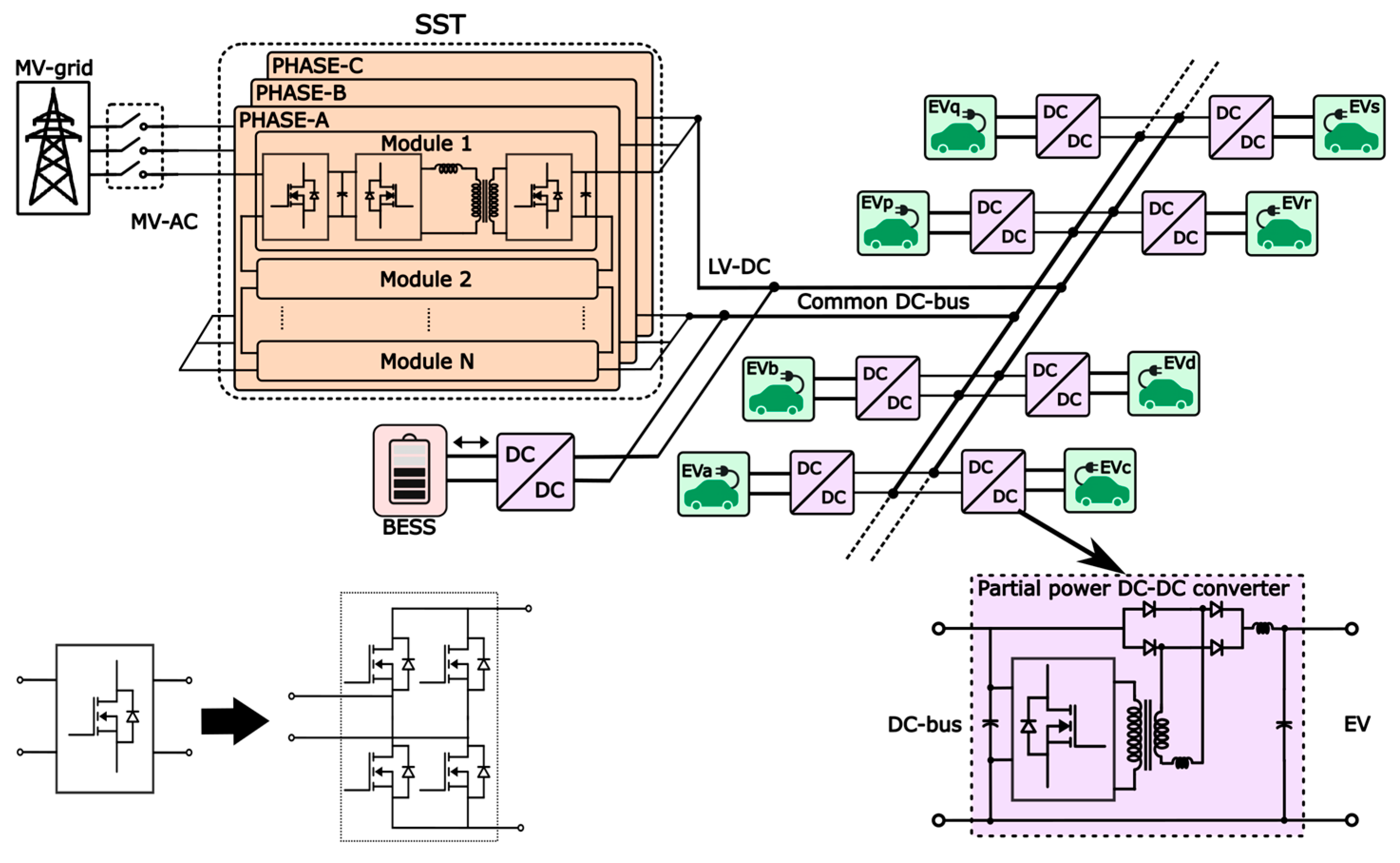
| [11] | LV-DC | SST | Absent due to PPCs | Non-isolated PPC DC-DC stage | Power-dense DC-DC stages, but galvanic EV–EV isolation is absent, and the costly SST is used. |
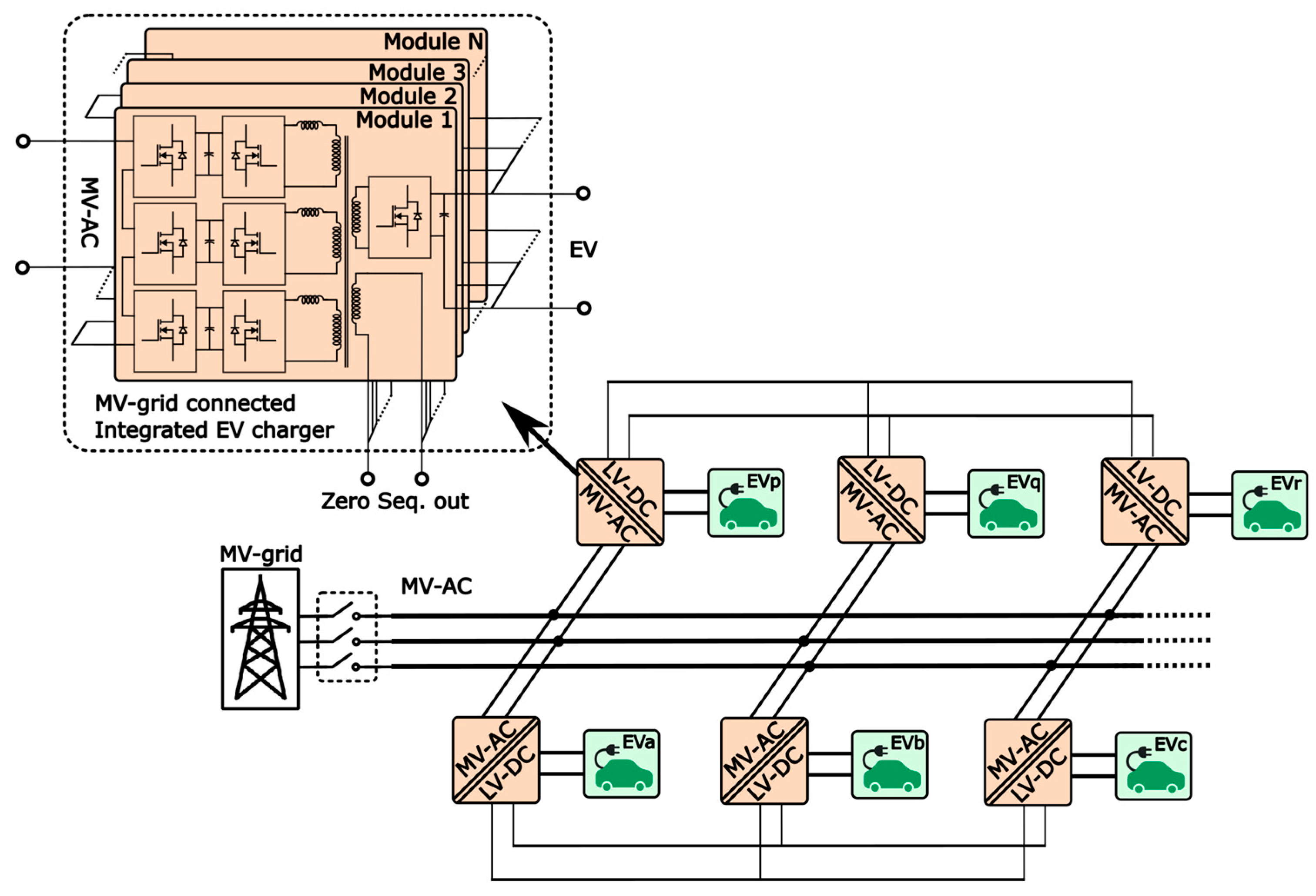
| [15] | MV-AC | SST | SST | - | Power-dense but has power-balancing challenges on the three-phase supply and uses the costly SST. |
| [21] | Bipolar LV-DC | LFPT | Absent | Non-isolated three-level DC-DC stage | Bipolar DC voltage-balancing challenges and absence of galvanic EV–EV isolation. |
| Existing EVFS | LV-DC at EV chargers | LFPT | Isolated DC-DC at EV side | Integrated on LV-AC side | BESS integration is at the LV-AC side, there is a distributed network architecture, and it requires further optimization. |
| Proposed EVFS | LV-DC | LFPT | Isolated reconfigurable LLC DC-DC | Non-isolated PPC DC-DC stage | LV-DC linked BESS, optimal choice of DC-DC stages, EV chargers grouped into zones, zonal isolations, and zonal interconnectors. |
| EVFS Architecture | AC-DC Converter Rating (MW) | DC-DC Converter Rating (MW) | Total (MW) | System Eff. (%) | ||
|---|---|---|---|---|---|---|
| Common AC-bus | EV side (156 × 350 kW) | 55 | EV side (156 × 350 kW) | 55 | 150 | <95.45 * |
| BESS side (35% of 55 kW) | 20 | BESS side (35% of 55 kW) | 20 | |||
| Total | 75 | Total | 75 | |||
| Common DC-bus | Grid side after peak shave, EV−BESS = 35 | EV side (156 × 350 kW) | 55 | 110 | 95.93 | |
| BESS side (35% of 55 kW) | 20 | |||||
| Total | 75 | |||||
| Existing commercial model | EV side (156 × 350 kW) | 55 | EV side (156 × 350 kW) | 55 | 150 | 95.45 |
| BESS side (35% of 55 kW) | 20 | BESS side (35% of 55 kW) | 20 | |||
| Total | 75 | Total | 75 | |||
| Proposed model | Grid side after peak shave, EV−BESS = 35 | EV side (156 × 350 kW) | 55 | 94 | 96.23 | |
| BESS PPC (20% of 0.35 × 55 kW) | 4 | |||||
| Total | 59 | |||||
| Structural Feature | Advantages |
|---|---|
| Zonal divisions with isolating DC switches |
|
| Zonal grouping of EV chargers |
|
| Interconnecting DC links across the grid-side AC-DC units |
|
| Interconnecting DC links across the charging zones of the DC network |
|
Disclaimer/Publisher’s Note: The statements, opinions and data contained in all publications are solely those of the individual author(s) and contributor(s) and not of MDPI and/or the editor(s). MDPI and/or the editor(s) disclaim responsibility for any injury to people or property resulting from any ideas, methods, instructions or products referred to in the content. |
© 2025 by the authors. Published by MDPI on behalf of the World Electric Vehicle Association. Licensee MDPI, Basel, Switzerland. This article is an open access article distributed under the terms and conditions of the Creative Commons Attribution (CC BY) license (https://creativecommons.org/licenses/by/4.0/).
Share and Cite
Althurthi, S.B.; Rajashekara, K. An Optimal Multi-Zone Fast-Charging System Architecture for MW-Scale EV Charging Sites. World Electr. Veh. J. 2025, 16, 389. https://doi.org/10.3390/wevj16070389
Althurthi SB, Rajashekara K. An Optimal Multi-Zone Fast-Charging System Architecture for MW-Scale EV Charging Sites. World Electric Vehicle Journal. 2025; 16(7):389. https://doi.org/10.3390/wevj16070389
Chicago/Turabian StyleAlthurthi, Sai Bhargava, and Kaushik Rajashekara. 2025. "An Optimal Multi-Zone Fast-Charging System Architecture for MW-Scale EV Charging Sites" World Electric Vehicle Journal 16, no. 7: 389. https://doi.org/10.3390/wevj16070389
APA StyleAlthurthi, S. B., & Rajashekara, K. (2025). An Optimal Multi-Zone Fast-Charging System Architecture for MW-Scale EV Charging Sites. World Electric Vehicle Journal, 16(7), 389. https://doi.org/10.3390/wevj16070389