Article

CLAMT Shifting Strategy with Dog Clutch and Active Synchronization for Electrified Tractors

1
TurkTraktor R&D Center, Camlica Business Center, Unalan, Cagla St. No:11, Istanbul 34700, Turkey
2
Electronics and Communication Engineering Department, Istanbul Technical University, Istanbul 34469, Turkey
*
Author to whom correspondence should be addressed.
World Electr. Veh. J. 2025, 16(11), 622; https://doi.org/10.3390/wevj16110622
Submission received: 19 September 2025 / Revised: 25 October 2025 / Accepted: 4 November 2025 / Published: 14 November 2025

Abstract

This study focuses on the development and optimization of a Clutchless Automated-Manual Transmission (CLAMT) system for tractors, aiming to enhance performance and efficiency across diverse operating conditions. It explores the use of a dog clutch mechanism as a simpler, robust alternative to traditional synchronizers. The main objective is to replace complex transmission setups—often requiring up to 32 gear ratios—with a system that operates efficiently using only two gears, without sacrificing versatility. Smooth gear engagement, even under varying loads and terrains, is a key challenge addressed. To ensure this, a Vehicle Management Unit (VMU) manages gear shifts and actively synchronizes speeds. The system leverages steady torque delivery through control algorithms and modern hybrid/electric powertrain capabilities. Two algorithmic approaches are implemented, and their performance is evaluated through empirical testing. Results show improvements in system simplicity, transmission reliability, and overall operational efficiency. The proposed approach offers valuable insights for future agricultural drivetrains, highlighting the potential of dog clutch-based architectures in reducing mechanical complexity while maintaining functional performance.

1. Introduction

While previous studies estimated that agriculture accounts for a substantial share of total emissions in developing countries, more recent analyses show that this contribution varies widely across nations—for example, from as high as 28% in Qatar to about 9% in Canada [1]. Therefore, reducing agricultural emissions is critical, especially in countries where it accounts for a large share of total emissions.
Electrification in agriculture offers a promising solution by replacing fossil fuel-dependent machinery with cleaner, electric alternatives. Due to the price increase in fossil fuels, which are a limited resource, and strict rules to reduce exhaust emissions, electric vehicles have attracted the world’s attention, and companies aim to quickly introduce these vehicles [2]. This transition not only reduces direct emissions but also promotes sustainable agricultural practices in line with global climate goals. Therefore, the adoption of electric agricultural technologies can play a vital role in reducing the environmental impact of agricultural activities.
The introduction of electrification for agricultural machinery can have many other advantages. Thanks to the broad revolutions per minute (RPM) range and high torque provided by electric motors, transmission systems can be significantly simplified. This advancement enables functions that previously required dozens of gears in internal combustion vehicles to be efficiently achieved with just two gears, highlighting the technical and functional advantages of electric drivetrains [3]. The operating costs of tractors can be significantly lowered not only through reduced power consumption but also by minimizing maintenance needs, thanks to their simplified mechanical design [4].
In modern agricultural machinery, electronic control systems play a critical role in optimizing gear engagement and ensuring smooth operation under varying field conditions. Traditionally, gear synchronization has relied on mechanical synchronizers or clutch mechanisms. However, advancements in software-driven control strategies open new avenues for more efficient and responsive transmission designs. This research involves using dog clutch mechanisms within CLAMT systems, which allow direct gear engagement with minimal mechanical complexity. CLAMT systems have low manufacturing costs, easy control and high efficiency [5]. However, the system has inherent drawbacks in the lack of torque transfer during the gear shifting [5,6]. In the literature, concerns regarding gear wear are frequently highlighted when using dog clutches [7]. The engagement process of a dog clutch involves direct contact between mating teeth at potentially high relative speeds, which can lead to localized stress and material degradation over time. Studies suggest that mitigating these effects requires careful design of the gear shift mechanism, precise control of engagement speed, and consideration of appropriate materials or surface treatments to enhance wear resistance.
From a software development perspective, integrating dog clutch mechanisms within a CLAMT framework requires advanced control algorithms that synchronize motor speeds and ensure timely engagement. Implementing dog clutch control allows for the development of algorithms that dynamically adjust engagement timing, improving efficiency and durability compared to traditional methods.

1.1. Literature Review

1.1.1. AMT-Based Shifting Control Systems

Automated-manual transmission (AMT) systems are perceived as an alternative solution that combines the strengths of automatic and manual transmissions. These systems provide several advantages, including improved fuel efficiency, enhanced driving comfort, easier gear shifting, and cost efficiency [8]. However, certain drawbacks can diminish these benefits. Key disadvantages include accelerated clutch wear, traction loss, and jerking during gear shifts. Such issues have driven research efforts in the literature to eliminate the use of clutch mechanisms in an AMT system. For example, one study [9] evaluated conventional gear-shifting methods against clutchless gear-shifting in terms of shift duration and power interruption time.
The comparison revealed that both the gear-shifting time and traction loss were reduced during upshifting and downshifting transitions, as demonstrated by the test results presented in Table 1.
Although there are only a small number of studies addressing the feasibility of removing the clutch, as Yu and Tseng underline in [2], this study explored the synchronization and engagement of a CLAMT system for tractors, focusing on the integration of electric drive systems and dog clutch mechanisms. By employing real-world tests and control-based approaches, the proposed system achieved effective gear engagement while maintaining operational efficiency and reliability under varying load conditions.

1.1.2. CVT-Based Shifting Control Systems

Continuously variable transmissions (CVT) differ from traditional gear-driven transmissions by providing a smooth transfer of torque across a wide speed range, with an infinite number of gear ratios, instead of discrete gear steps.
This system is usually constructed with a belt or chain mechanism and tapered pulleys, as shown in Figure 1. In the CVT system illustrated in Figure 1, power is transmitted via a belt or chain running between two cone-shaped pulleys. The effective diameter of each pulley is adjusted by moving the pulley halves closer together or farther apart. As one pulley’s diameter increases, the other’s decreases, allowing the belt or chain to ride at different positions. This mechanism enables a continuous and stepless change in the transmission ratio between input and output shafts, optimizing engine performance for varying speed and torque requirements.
CVTs enhance engine efficiency by continuously adjusting the gear ratio. The main benefit of CVTs is their ability to keep the engine operating within its optimal efficiency range, leading to reduced fuel consumption and a smoother driving experience. Modern CVT systems are implemented in tractors to optimize power distribution and enhance energy efficiency [11]. However, challenges such as limitations in the belt mechanism, energy loses during high torque demands, and vibrations during gear ratio transitions have been noted. The adoption of CVT technology is growing, particularly in hybrid and electric vehicles, making it an important research area for improving both performance and longevity.

1.1.3. Actuation Methods for Shifting

In the literature, it is observed that gear selection processes are predominantly carried out through the electric servo motor actuation method. Specifically, it is highlighted that servo motor control is commonly preferred for precisely executing gear shifts in automated mechanical transmission systems.
Despite the fact that electro-mechanical actuation systems are commonplace in automotive and commercial vehicle transmissions [5], they are not preferable in terms of displacement, compressive force, tensile force, or output power, as it can be seen from Table 2. In the experimental study by Pustavrh et al. [12], hydraulic, pneumatic, and electric linear actuators were compared and scored between 1 and 10 based on key performance criteria such as velocity and acceleration. According to the results, hydraulic actuators were found to be the most suitable option for applications requiring high force. The detailed scores for each actuation method can be seen in Table 2.
The integration of hydraulic systems in tractors has long been a standard due to their versatility and reliability in handling high loads and providing precise control. These systems are crucial in performing various tasks, such as lifting, pulling, and driving power take-off (PTO) driven implements. Given that the hydraulic system is inherently present in most tractors, it provides a significant advantage when designing new drivetrain solutions. The presence of a hydraulic system in the tractor effectively eliminates the weight advantage typically offered by electrical control systems. In this study, hydraulic actuators are incorporated into the gearbox system by leveraging this established infrastructure.

1.2. Background

Although electrified tractor architectures are becoming more common, most current designs still rely on transmission systems originally developed for ICE tractors. There are only a limited number of studies in the literature that specifically analyze transmission systems for electric tractors. In this work, possible transmission and gear systems in the literature have been reviewed and their suitability for electrified agricultural applications has been discussed. Current transmission systems for electrified tractors, such as multi-speed gearboxes and conventional clutch mechanisms, present significant limitations in terms of mechanical complexity, maintenance requirements, and operational efficiency. While AMT and CVT have been adopted in some applications, these solutions often struggle to deliver the required durability and performance under the high-torque, low-speed conditions typical in agricultural environments.
Additionally, issues such as clutch wear, traction loss, and increased system weight further reduce their suitability for modern electrified tractors. The literature also highlights concerns regarding gear wear and synchronization challenges, especially when using dog clutch mechanisms [7]. These drawbacks underscore the need for innovative transmission architectures that simplify the drivetrain, reduce maintenance, and maintain high efficiency. The proposed CLAMT system directly addresses these gaps by leveraging the advantages of electric motors and a simplified two-speed gearbox, offering a robust and efficient solution tailored for agricultural applications.
The role of hydraulic actuators in gear selection has been less studied in the literature, presenting an opportunity to assess the potential benefits of hydraulic systems. Given the advantage of the hydraulic system’s presence in the tractor and the lack of exploration of hydraulic actuators in transmission systems in the literature, the use of a hydraulic actuator in this study will make it valuable.

1.3. Objective

The objective of this study is to develop and experimentally validate a simplified CLAMT system for electrified tractors, utilizing a dog clutch mechanism and active synchronization algorithms. The proposed system aims to overcome the limitations of conventional multi-speed gearboxes and clutch-based transmission architectures, which are still widely used in electric tractor designs despite their mechanical complexity, maintenance requirements, and inefficiency under agricultural operating conditions. By leveraging the broad torque and speed range of electric motors, the study seeks to demonstrate that efficient tractor operation can be achieved with only two gears—field and road—thus reducing mechanical complexity, improving reliability, and minimizing maintenance. The research further aims to provide a robust control strategy using a VMU to ensure smooth gear engagement and optimal performance across diverse agricultural scenarios.
Specifically, this work targets achieving the same operational capabilities as a 12-speed internal combustion tractor of equivalent power, but with only two gears in the electric tractor. In doing so, the study also focuses on selecting and implementing the most suitable transmission type for the vehicle’s real-world working conditions.

1.4. Project Scope

The scope includes the development of a dual-mode gearbox utilizing a dog clutch mechanism, with two distinct gear ratios optimized for field and road operations. The research covers the creation of control algorithms—both with and without active speed synchronization—implemented via a VMU to ensure smooth and reliable gear shifting. The VMU software was developed using the C programming language, enabling real-time control and integration with the tractor’s embedded systems. Experimental tests are conducted to evaluate the performance, controllability, and operational efficiency of the proposed system under real-world agricultural conditions. The study is limited to the transmission architecture, control strategy, and embedded software; aspects such as battery management, overall tractor design, or non-transmission-related powertrain components are outside the scope of this work.
The findings aim to demonstrate that the proposed system can achieve the same operational capabilities as conventional multi-speed internal combustion tractors, but with significantly reduced mechanical complexity and maintenance requirements.

2. Preliminaries

Tractors differ significantly from other vehicles in their operational requirements, as they must generate high torque at very low speeds to perform precision agricultural tasks on high-resistance terrains. Unlike conventional vehicles, tractors are designed to withstand prolonged and heavy-duty operations, with an emphasis on reduced and easily manageable maintenance intervals. These requirements impose stringent demands on transmission systems, where durability, efficiency, and adaptability are paramount. Conventional tractor transmissions rely on multi-speed gearboxes and clutch systems to meet these demands.

2.1. Motivation and Problem

In tractors equipped with IC engines, 12-speed or 24-speed gearboxes, typically configured with 3 range gears and 4 regular gears, are commonly used. These gearboxes are designed to accommodate the specific speeds required for agricultural operations, such as planting and harvesting crops like potatoes, tomatoes, and other vegetables. The inefficient performance of IC engines at certain speed ranges necessitates the use of multiple gear options. Different gears help keep the engine operating within its most efficient speed range, aiming to optimize fuel consumption and performance. However, even in their most efficient operating zones, the efficiency of IC engines rarely exceeds 40% [13]. IC engines operate efficiently within a narrow RPM range; outside this range, either fuel consumption increases significantly, or insufficient power is generated.
As electrification trends gain momentum in agricultural machinery, there is a pressing need to develop transmission systems that are not only efficient and durable but also simplified to meet the demands of electrified drivetrains. Existing solutions, such as complex multi-gear systems, may no longer be practical or efficient for electric tractors. This impracticality is mainly due to increased mechanical complexity, higher manufacturing and maintenance costs, greater system weight, and reduced power transmission efficiency. In addition, traditional clutch systems are prone to wear and tear, requiring frequent maintenance and reducing operational reliability over time. Therefore, innovative approaches focusing on simplifying the transmission architecture while maintaining performance are becoming increasingly essential. To address these challenges, innovative approaches focusing on simplifying the transmission architecture while maintaining performance are becoming increasingly essential.
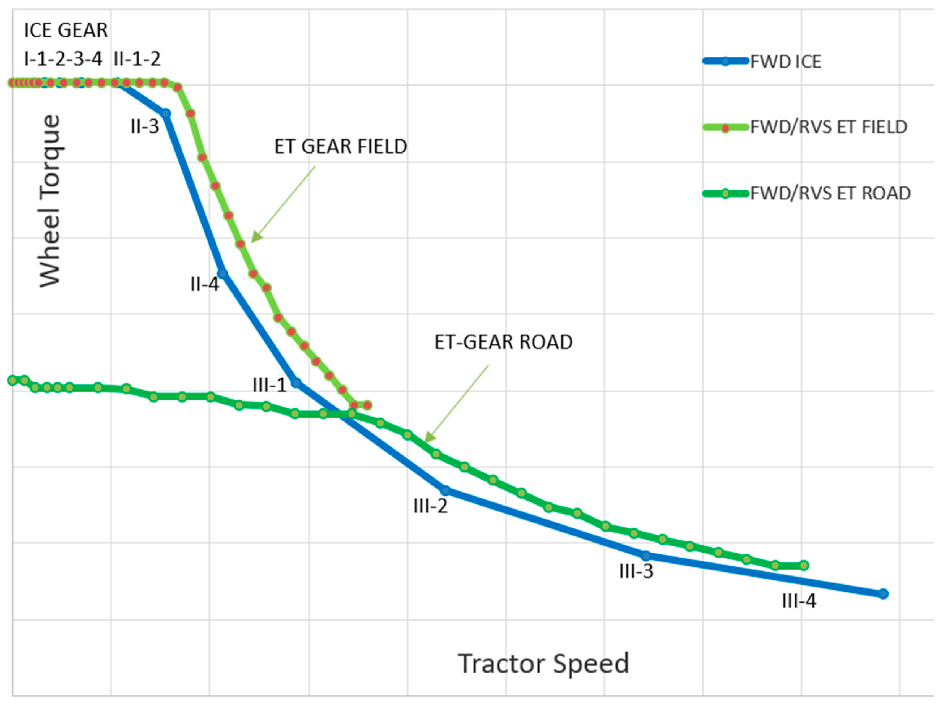
Ersarı and Gündoğdu [3] have introduced gear ratio optimization for electrified tractors. Figure 2 illustrates the optimization results for gear ratios, highlighting the ability of the electric motor to achieve high wheel torques over a wide RPM range.
Figure 2 illustrates the relationship between wheel torque and tractor speed for three configurations: an ICE tractor and an electric tractor operating in two gear modes—field gear and road gear. The blue curve represents the ICE tractor, while the light green and dark green curves correspond to the electric tractor in field and road gear, respectively.
On the ICE tractor curve, gear positions labeled as I-1, I-2, II-1, II-2, etc., indicate the presence of three main gears combined with four auxiliary ranges, resulting in a total of 12 gear ratios. Each gear point on the blue curve demonstrates how the ICE tractor achieves specific wheel torque and speed combinations by utilizing these 12 gears. This configuration ensures that the tractor operates within the engine’s optimal efficiency range across varying load and speed conditions.
The blue curve serves as the performance reference for garden-type tractors intended for both field and road applications. Consequently, the electric tractor must match or exceed this benchmark. Unlike ICE engines, which require multiple gears to maintain efficiency, electric motors exhibit efficiencies of approximately 95% and deliver high torque over a wide speed range. Leveraging these characteristics, the electric tractor achieves comparable performance using only two gear ratios: one for field operations (0–16 kph) and another for road transport (16–40 kph).
Initially, a single-gear solution was considered. However, when operating solely in field gear, performance in the 16–40 kph range fell below the ICE reference curve. Conversely, using only road gear resulted in insufficient torque at speeds below 16 kph. Therefore, a two-gear configuration was adopted to ensure full coverage of the required torque-speed envelope.
The motivation of this study is to implement the control of a two-speed CLAMT system, which eliminates the complexity and maintenance requirements of a clutch, using a VMU. Moreover, this study utilizes an introduced dual-mode gearbox with field and road gears, which significantly reduces the total number of gear shifts over the tractor’s lifetime. With fewer gear shifts, wear and tear on the transmission components are minimized, contributing to improved durability and reduced maintenance requirements.

2.2. Essential Components

2.2.1. Mounted Dog Clutch

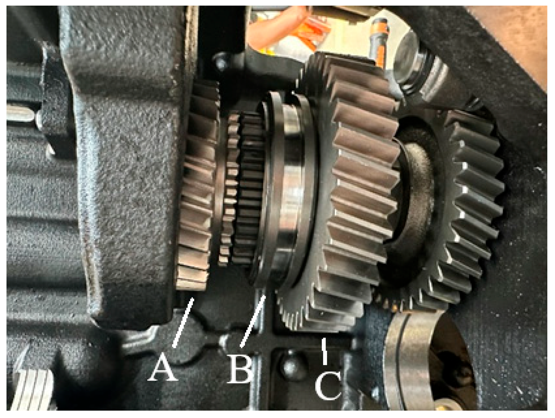
The proposed system utilizes a dog clutch mechanism with two gears and a central fork, as depicted in Figure 3. The fork moves between the neutral position and the engagement positions for the field and road gears. Figure 4 below illustrates the mounted dog clutch gear of the electric tractor. By moving the central fork (B), the field (C) and road (A) gear will be engaged. This configuration allows the wheel torque-speed curve achieved by a 12-gear internal combustion tractor to be replicated with just two gears.

2.2.2. Gearbox Design

Traditional tractor gearboxes often rely on complex mechanical systems, with multiple gears and components designed to handle the high torque and varying operational conditions. However, as electric motor technology offers more efficient power delivery across a wide RPM range, the design of tractor transmissions has become simpler and more sophisticated. This study is focused on developing a dual-mode gearbox that integrates sensors and actuators for seamless operation while ensuring that the performance objectives of internal combustion engine tractors are met or exceeded.
The dual-mode gearbox features a combination of field and road gears, each optimized for specific operational conditions. In order to provide robustness for the system, there are essential components such as temperature sensors, pressure sensors, and proportional valves, each playing a crucial role in monitoring and adjusting gearbox performance.
The internal configuration of the gearbox, as illustrated in Figure 4, includes a single input pressure sensor responsible for continuously verifying whether the hydraulic fluid entering the valve assembly exceeds 190 bar. Additionally, a temperature sensor monitors the fluid to ensure it remains below 85 °C. Both sensors generate analog output signals, enabling real-time monitoring and control.
Furthermore, an analog position sensor is integrated into the system to monitor the location of the gear-shifting fork. The sensor output enables identification of the gear state—whether it is in road mode, field mode, or neutral—thus supporting accurate gear selection and operational control.
Optimizing the pressure and temperature value is key to achieving consistent performance. By accurately controlling these elements, durability is aimed to be enhanced, wear reduced, and the overall efficiency of the electric tractor’s drivetrain improved. This approach not only simplifies the gearbox design but also contributes to the overall reliability and ease of maintenance, which is essential for modern agricultural machinery. The integration of these sensors allows for real-time monitoring and dynamic adjustments, ensuring the system performs optimally in both field and road conditions.
Table 3 below presents the optimal working requirements for the shifting process.

2.2.3. Proportional Valves

The gearbox includes two proportional valves responsible for enabling the movement of the fork that facilitates gear engagement or disengagement. These proportional valves are controlled using the pulse width modulation (PWM) technique. The current-to-pressure curve provided by the manufacturer [14] is shown in Figure 5.
Achieving an output pressure of 18.5 bar is possible by providing the corresponding current value. The proportional valve is driven by PWM signal, and the current drawn by the valve is calculated by dividing the average voltage supplied via the PWM signal by the coil resistance. Proportional voltage is given by Equation (1).
V P W M = V s u p p l y × D u t y   C y c l e
In order to achieve 18.5 bar pressure at output, it is necessary to provide 540 mA for proportional valve, see Figure 5. Supply current can be calculated using Equation (2).
I = V P W M R C o i l
Finally, required duty cycle can be obtained according to curve as given in Equation (3).
D u t y   C y c l e = 540   mA × R c o i l V s u p p l y

3. Proposed Work

3.1. Gear-Shifting Algorithms

Due to the high inertia of internal combustion engines, the use of a clutch is typically required for gear shifting [2]. However, the low inertia and precise control capabilities of electric motors eliminate this necessity.
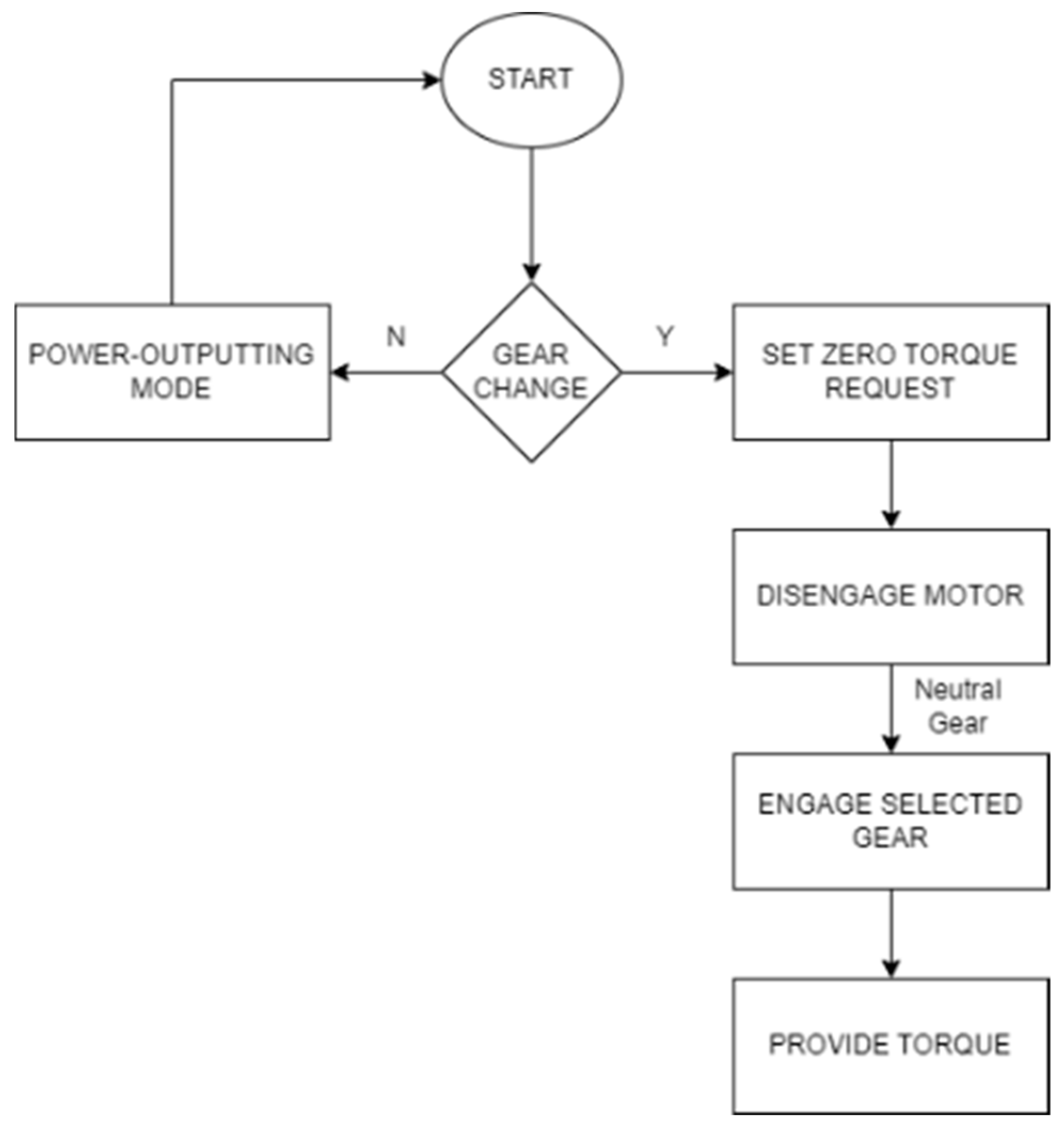
The algorithms are analyzed in two stages based on the presence or absence of speed synchronization. The algorithm without speed synchronization includes only four sequences: torque unloading, gear disengagement, gear engagement, and torque loading. This study presents two methodologies for performing the shifting phases without a clutch by utilizing a centralized control unit, leveraging the advantages of electric motor technology.

3.1.1. Gear-Shifting Algorithm Without Speed Synchronization

This algorithm performs the gear-shifting process without utilizing active speed synchronization. The first phase involves torque unloading, where the torque transmitted by the drivetrain is reduced to near zero. This is achieved by finely controlling the electric motor to eliminate torque transfer to the transmission system, ensuring minimal resistance during the gear disengagement phase. Once torque unloading is achieved, the gear disengagement phase is initiated by mechanically decoupling the engaged gear.
Without active synchronization, the subsequent gear engagement relies on the natural deceleration of the motor and transmission components. This approach simplifies the control strategy but may lead to extended shifting times and increased mechanical stress. The algorithm’s flowchart, depicted in Figure 6, provides a detailed visualization of the sequential steps. While effective for basic applications, this method may limit operational efficiency in scenarios requiring rapid or precise gear changes.

3.1.2. Gear-Shifting Algorithm with Speed Synchronization

The inclusion of active speed synchronization in this algorithm enhances the precision and efficiency of the gear-shifting process. Following torque unloading, the electric motor’s speed is actively adjusted to match the target gear’s speed ratio, utilizing the gear ratios of the transmission system. This synchronization minimizes the relative speed difference between the gears, allowing for smoother and faster engagement [15]. Torque unloading remains critical in this process to ensure a seamless transition to the speed synchronization phase. After the desired motor speed is reached, the gear is engaged, completing the shifting process. This method reduces mechanical wear and improves shifting consistency, particularly in high-demand operational conditions.
Figure 7 illustrates the algorithm’s flowchart, highlighting the additional synchronization step. This approach demonstrates better performance compared to the non-synchronized method, addressing the limitations of increased wear and prolonged shift times by leveraging the motor’s control capabilities.
The critical phase of this algorithm is speed synchronization, where the primary objective is to align the rotational speeds of the target gear and the electric motor. While the speed of the electric motor is adjustable, the speed and torque of the wheel-connected gears remain uncontrollable. At any given time, t, the synchronization must be achieved using the following equations, Equations (4) and (5), ensuring the rotational speeds of the electric motor and the gear are matched effectively.
M o t o r R P M × G e a r R a t i o R O A D = R o a d G e a r R P M
M o t o r R P M × G e a r R a t i o F I E L D = F i e l d G e a r R P M

3.2. System Architecture

The proposed control system utilizes a VMU, which incorporates a 32-bit microcontroller and operates on a task-scheduled architecture with a minimum task period of 20 ms. The VMU serves as the core component in managing the gear-shifting process, ensuring precise execution of each phase: torque unloading, gear disengagement, active speed synchronization, gear engagement, and torque recovery. The control structure and all related components are presented in Figure 8.
Through the selection of turtle mode within the 0–16 kph range and rabbit mode within the 16–40 kph range. During a gear shift sequence, even if the accelerator is pressed, torque is momentarily unloaded to enable smooth disengagement and engagement.
The gear-shifting process begins with torque unloading, where motor torque is reduced to zero to eliminate the load on the current gear. Once torque unloading is complete, the system proceeds to gear disengagement, facilitated by precise control of proportional valves using PWM signals. The movement speed of the shift fork is regulated based on the current-to-pressure characteristics of these valves, ensuring controlled and smooth disengagement.
The most critical phase in the sequence is active speed synchronization. During this phase, the electric motor speed is actively adjusted to match the target gear speed, calculated based on the gear ratio and real-time feedback from speed sensors. Since the electric motor can regulate its speed and torque rapidly [16], synchronization can be achieved more efficiently compared to conventional systems. This eliminates the need for additional components such as synchronizers, reducing system complexity and mechanical losses.
Following speed synchronization, the system proceeds to gear engagement, where the proportional valves guide the shift fork to lock the target gear into place. Finally, torque recovery is initiated, gradually ramping up the torque to restore the requested power delivery. Throughout this process, system parameters such as temperature, pressure, and actuator position are continuously monitored to ensure safe and reliable operation under varying load and speed conditions.
By integrating real-time control algorithms with advanced electric motor capabilities, the proposed architecture enables smooth gear shifting without a clutch while aiming to enhance operational efficiency and system performance. Compared to conventional internal combustion systems, this approach leverages the low inertia and controllability of electric motors to enhance drivability, reduce mechanical wear, and optimize torque delivery across different speed ranges. This structure facilitates the implementation of the CLAMT concept in tractors while simplifying the system by eliminating components such as synchronizers and clutches, which contribute to increased complexity.

3.3. Shifting Strategy

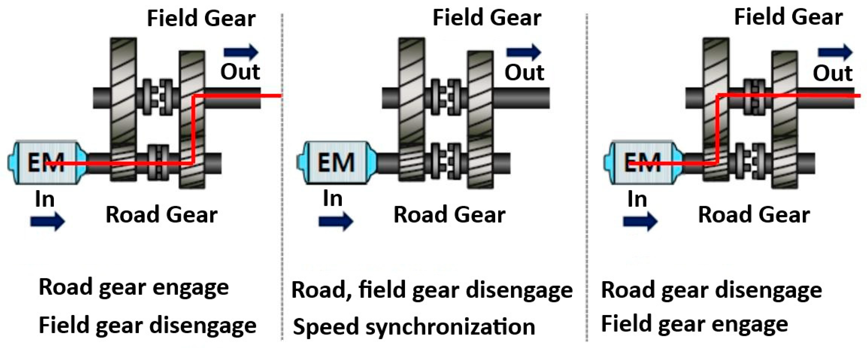
The gear-shifting process without using a clutch can be divided into five stages: torque unloading, gear disengagement, active speed synchronization, gear engagement and torque recovery [5,9,15,17,18]. The power flow is illustrated from left to right in Figure 9.
In the initial state, the power generated by the electric motor is transmitted to the wheels via the road gear.
In the intermediate state, the torque output of the motor is first reduced to zero. Subsequently, the gears are disengaged. To transition into the field mode, the rotational speeds of the gear connected to the electric motor and the gear on the driveline side are synchronized. Once synchronization is achieved, the gears are re-engaged. Following this process, torque is transmitted to the wheels through the electric motor and the field gear.
In the final state, the power flow is directed to the wheels via the field gear, completing the transition into field operation.

4. Experimentation

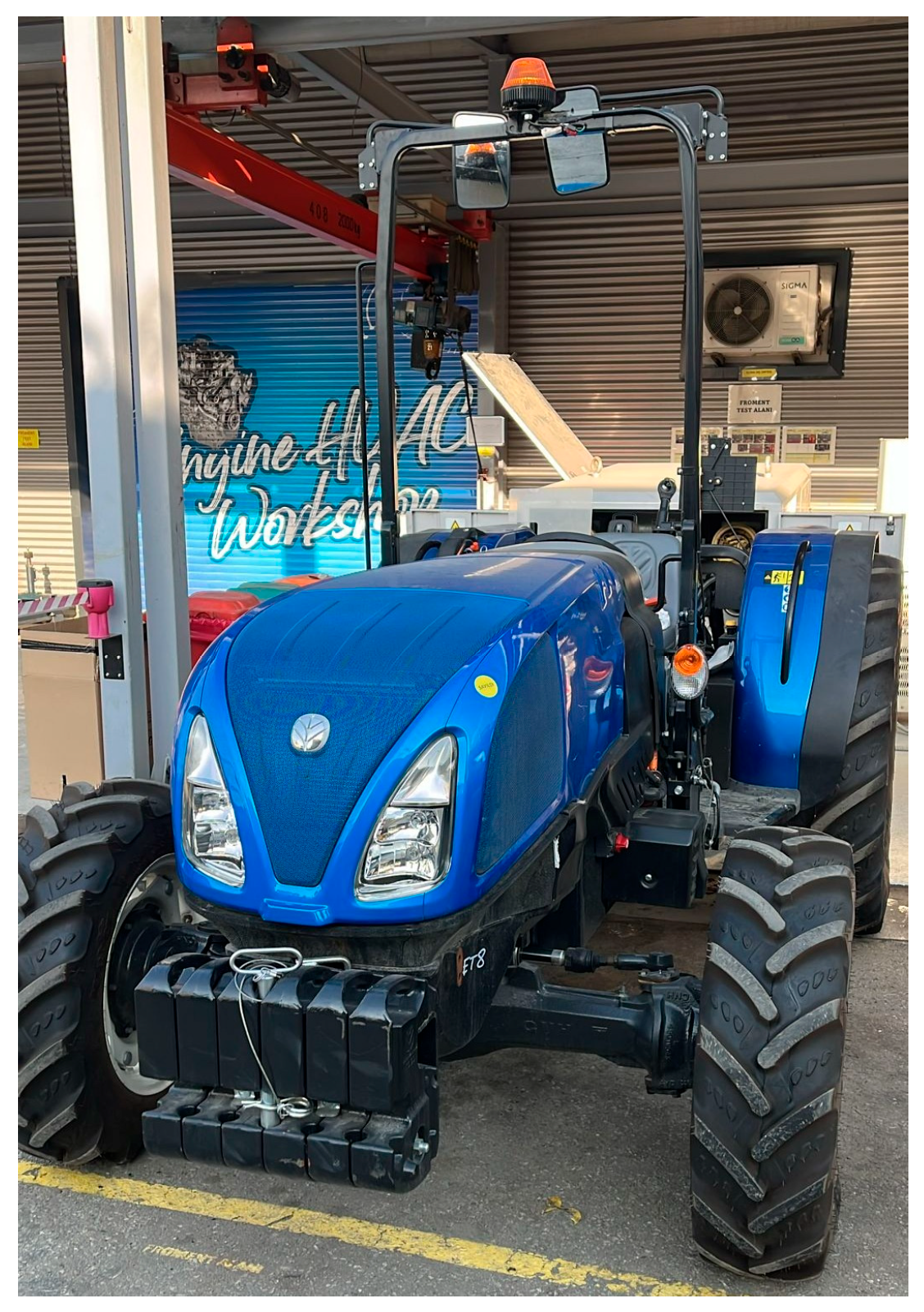
The experimental study focuses on evaluating the real-world effects of the related system through two distinct test scenarios. The first test scenario does not include speed synchronization; however, the second test scenario includes speed synchronization. The data collection process was conducted using the Vector CANalyzer tool, widely employed in automotive applications for its robust capabilities in real-time data acquisition and analysis. The vehicle used for testing purposes can be seen in Figure 10.

4.1. Testing System Without Speed Synchronization

In the first test scenario, the tractor was placed on a special riser, ensuring that the wheels were not in contact with the ground, thereby eliminating opposing torque. This setup simulated a theoretical environment where active speed synchronization was not enabled during gear-shifting events. As a result, audible squealing noises were frequently observed, particularly during transitions between gears. This outcome highlighted the significant role of speed matching in achieving smooth and efficient gear engagements. The absence of active synchronization underlined the limitations of the system when subjected to uncontrolled gear speed differentials, leading to abrupt and inefficient shifting behavior.
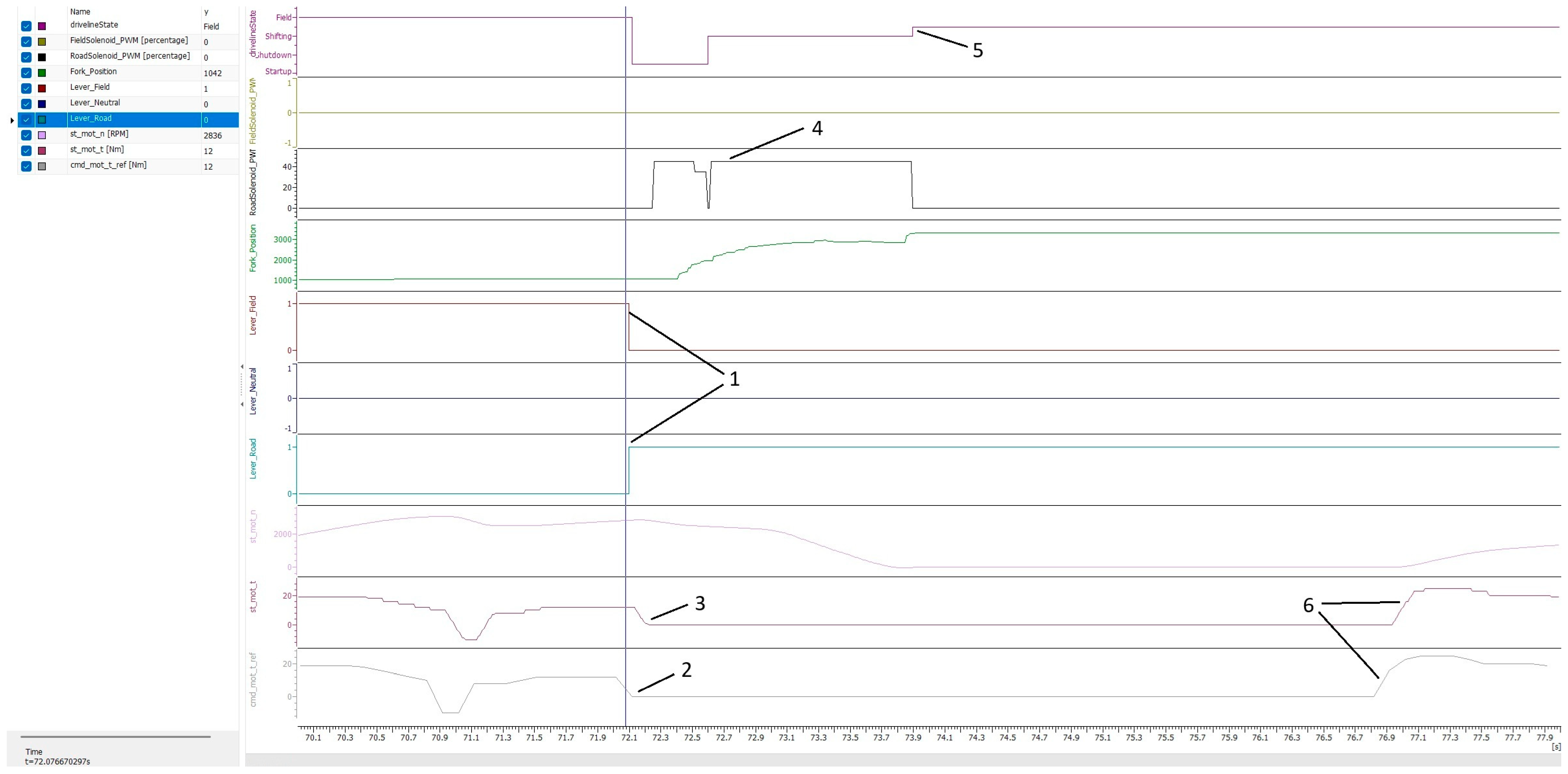
The result of the first test case is visually represented in Figure 11, where specific data points are annotated to illustrate the critical observations.
It can be observed from Figure 11 that when the driver selects the desired gear, the selected gear variable becomes true, and the other gear variable becomes false (1). The torque command for the electric motor is initially set to zero (2). To confirm this condition, the feedback message from the electric motor, indicating the actual torque value, can be monitored (3). In the first phase of the gear-shifting process, the gearbox transitions to the neutral state. Following the confirmation of the neutral state and the reduction in torque to zero, the shifting phase is initiated, and valve activation is triggered (4). During both the neutral and shifting phases, the control torque remains at zero to ensure smooth operation. Once the desired gear is engaged (5), the system delivers the commanded torque to the wheels through the permanent magnet synchronous motor (PMSM) and the selected gear (6). In Figure 11, the inconsistencies in torque feedback during unsynchronized transitions can be observed, corresponding to the audible squealing noises detected in the first test.

4.2. Testing System with Speed Synchronization

The second test scenario was conducted with the tractor’s wheels in direct contact with the ground, allowing the system to experience opposing torque reflective of real-world operating conditions.
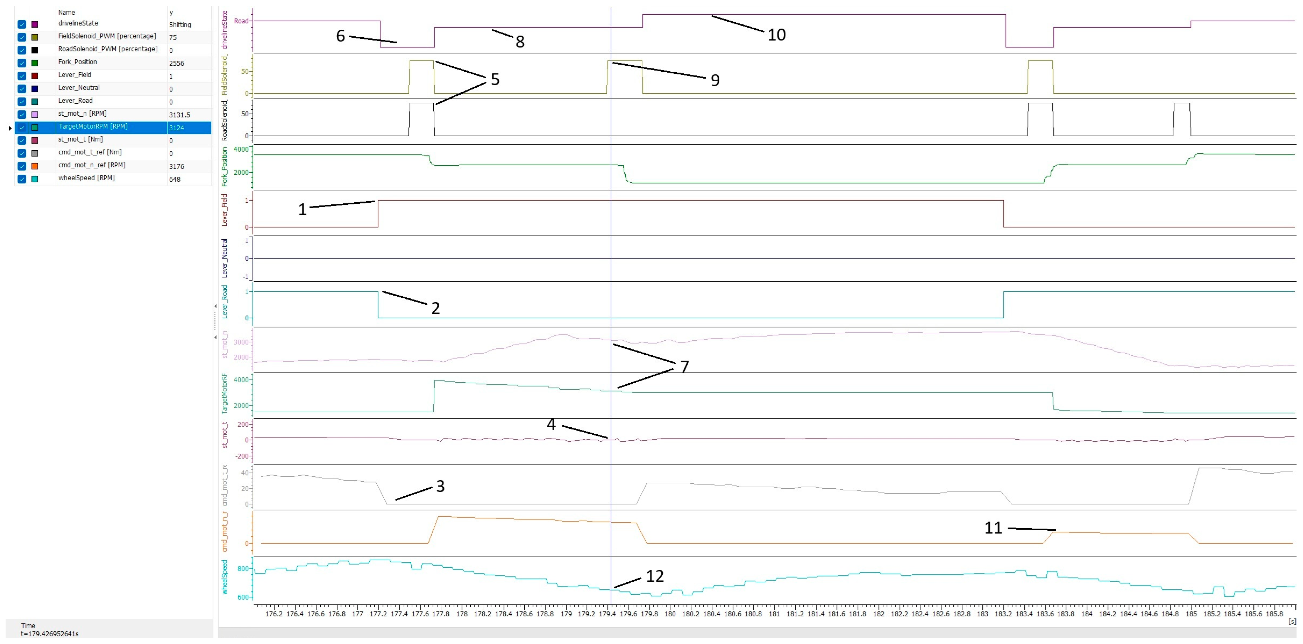
As shown in Figure 12, when the driver selects the desired gear, the desired gear variable becomes true (1), and the other gear variable becomes false (2). The torque command for the PMSM is initially set to zero (3). The feedback message from the PMSM confirms the actual torque value (4). For the disengagement process, both of the valves are triggered (5). The gear state becomes neutral, which means that gears are disengaged (6). The wheel speed is continuously monitored via the speed sensor (12). During the shifting phase (8), the target motor RPM is calculated. Once the difference between the feedback from the PMSM and the target motor RPM falls below a specific threshold (7), the field gear valve is activated (9). After the engagement process is completed (10), torque is transferred from the electric motor through the field gear to the wheels (11).
In this case, the active speed synchronization algorithm was enabled. The results showcased a marked improvement, as the gear transitions occurred seamlessly without the presence of squealing sounds.

5. Conclusions

The experimental results presented in Figure 11 and Figure 12 clearly demonstrate the impact of the proposed control algorithms on system controllability and performance. As shown in Figure 11, gear shifting without active speed synchronization resulted in audible noise and irregular torque feedback, indicating limited controllability. In contrast, Figure 12 illustrates that the implementation of active speed synchronization enabled smooth and precise gear transitions, confirming the effectiveness of the developed control strategy in improving both controllability and overall transmission performance.
The streamlined design of the CLAMT system, combined with precise speed synchronization methods, demonstrated the potential to enhance overall performance while reducing system complexity. These advancements simplify operation for end-users, making modern tractors both efficient and accessible.
Additionally, the infrequent nature of road-to-field gear transitions in agricultural operations provides a practical advantage, as it minimizes wear and tear on the transmission system. This characteristic allows for the reliable implementation of the dog clutch mechanism while ensuring durability over the tractor’s operational lifespan. The insights gathered from field data validated the effectiveness of the proposed approach and highlighted its suitability for real-world applications.
Overall, this research contributes to the advancement of transmission systems for agricultural applications by highlighting the simplicity and efficiency of electric motor usage in tractor transmissions and gear shift mechanisms. This architecture not only simplifies operations for users but also offers significant advantages for the industry, particularly in terms of after-sales support and maintenance.

Author Contributions

Conceptualization, B.B., E.O.G. and M.G.; methodology, B.B. and E.O.G.; software, B.B.; validation, B.B., E.O.G. and M.G.; formal analysis, B.B.; investigation, B.B.; resources, E.O.G. and M.G.; data curation, B.B.; writing—original draft preparation, B.B.; writing—review and editing, B.B., E.O.G. and M.G.; visualization, B.B.; supervision, E.O.G. and M.G.; project administration, E.O.G. and M.G. All authors have read and agreed to the published version of the manuscript.

Funding

This research received no external funding.

Data Availability Statement

No new data were created or analyzed in this study. Data sharing is not applicable to this article.

Acknowledgments

During the preparation of this study, author Bertug Bingol, Ece Olcay Gunes and Murat Gundogdu used Vector CANAlyzer 15 for the purposes of collecting and processing data. The authors have reviewed and edited the output and take full responsibility for the content of this publication.

Conflicts of Interest

The authors declare no conflicts of interest.

Abbreviations

The following abbreviations are used in this manuscript:
CLAMTClutchless Automated-Manual Transmission
VMUVehicle Management Unit
RPMRevolutions Per Minute
AMTAutomated-Manual Transmission
CVTContinuously Variable Transmission
PTOPower Take-Off
ICInternal Combustion
PWMPulse Width Modulation
CANController Area Network
PMSMPermanent Magnet Synchronous Motor

References

  1. Khan, R.; Alabsi, A.A.N.; Muda, I. Comparing the effects of agricultural intensification on CO2 emissions and energy consumption in developing and developed countries. Front. Environ. Sci. 2023, 10, 1065634. [Google Scholar] [CrossRef]
  2. Tseng, C.-Y.; Yu, C.-H. Advanced shifting control of synchronizer mechanisms for clutchless automatic manual transmission in an electric vehicle. Mech. Mach. Theory 2015, 84, 37–56. [Google Scholar] [CrossRef]
  3. Gündoğdu, M.; Ersarı, M. Tractor transmission gear ratio optimization. Eng. Perspect. 2024, 4, 95–99. [Google Scholar] [CrossRef]
  4. Scolaro, E.; Beligoj, M.; Perez Estevez, M.; Alberti, L.; Renzi, M.; Mattetti, M. Electrification of agricultural machinery: A review. IEEE Access 2021, 9, 164520–164541. [Google Scholar] [CrossRef]
  5. Lu, Z.; Tian, G.; Onori, S. Time-optimal coordination control for the gear-shifting process in electric-driven mechanical transmission (dog clutch) without impacts. SAE Int. J. Electrified Veh. 2020, 9, 155–168. [Google Scholar] [CrossRef]
  6. Tian, Y.; Yang, H.; Mo, W.; Zhou, S.; Zhang, N.; Walker, P.D. Optimal coordinating gearshift control of a two-speed transmission for battery electric vehicles. Mech. Syst. Signal Process. 2020, 136, 106521. [Google Scholar] [CrossRef]
  7. El Morsy, M.; Achtenova, G.; Pakosta, J. Smoothness of Maybach dog clutch shift in the automotive gearbox. In Proceedings of the 13th International CTI Symposium, Berlin, Germany, 8–11 December 2014. [Google Scholar]
  8. Taguchi, Y.; Soga, Y.; Mineno, A.; Kuzuya, H.; Horiuchi, I.; Ueda, Y.; Miyazaki, T. Development of an automated manual transmission system based on robust design. SAE Tech. Pap. 2003, 9. [Google Scholar] [CrossRef]
  9. Zhong, Z.; Kong, G.; Yu, Z.; Xin, X.; Chen, X. Shifting control of an automated mechanical transmission without using the clutch. Int. J. Automot. Technol. 2012, 13, 487–496. [Google Scholar] [CrossRef]
  10. Yamaha Motor Co. Ltd. Easy-to-Use CVT-Equipped Engines. Available online: https://global.yamaha-motor.com/design_technology/technology/spread/003/ (accessed on 4 April 2025).
  11. Jensen, T.A.; Antille, D.L.; Tullberg, J.N. Improving on-farm energy use efficiency by optimizing machinery operations and management: A review. Agric. Res. 2024, 14, 15–33. [Google Scholar] [CrossRef]
  12. Pustavrh, J.; Hočevar, M.; Podržaj, P.; Trajkovski, A.; Majdič, F. Comparison of hydraulic, pneumatic and electric linear actuation systems. Sci. Rep. 2023, 13, 20938. [Google Scholar] [CrossRef] [PubMed]
  13. Rajagopalan, A.; Washington, G.; Rizzoni, G.; Guezennec, Y. Development of Fuzzy Logic and Neural Network Control and Advanced Emissions Modeling for Parallel Hybrid Vehicles; National Renewable Energy Laboratory: Golden, CO, USA, 2003. [Google Scholar]
  14. Tecnord. Datasheet. Available online: https://www.tecnord.com/cartridge-valves/proportional-controls/pressure-reducing-relieving/ (accessed on 11 April 2025).
  15. Lei, Y.; Hu, J.; Fu, Y.; Sun, S.; Li, X.; Chen, W.; Hou, L.; Zhang, Y. Control strategy of automated manual transmission based on active synchronization of driving motor in electric bus. Adv. Mech. Eng. 2019, 11, 1–17. [Google Scholar] [CrossRef]
  16. Li, L.; Wang, X.; He, K.; Liu, Y.; Liu, C. Position and force switching control for gear engagement of automated manual transmission gear-shift process. J. Dyn. Syst. Meas. Control. 2018, 140, 081010. [Google Scholar] [CrossRef]
  17. Xu, X.; Luo, Y. Modeling and analysis of gear shifting process of non-synchronizer AMT based on collision model. IEEE Access 2021, 9, 13354–13367. [Google Scholar] [CrossRef]
  18. Yu, C.-H.; Tseng, C.-Y. Research on gear-change control technology for the clutchless automatic-manual transmission of an electric vehicle. J. Automob. Eng. 2013, 227, 1446–1458. [Google Scholar] [CrossRef]
Figure 1. The structure of a CVT system [10].
Wevj 16 00622 g001
Figure 2. Gear ratio optimization results from [3].
Wevj 16 00622 g002
Figure 3. Mounted dog clutch gear.
Wevj 16 00622 g003
Figure 4. Gearbox design.
Wevj 16 00622 g004
Figure 5. Current-to-pressure curve of proportional valves [14].
Wevj 16 00622 g005
Figure 6. Flowchart without active speed synchronization.
Wevj 16 00622 g006
Figure 7. Flowchart with active speed synchronization.
Wevj 16 00622 g007
Figure 8. VMU-CLAMT structure.
Wevj 16 00622 g008
Figure 9. Gear-shifting strategy.
Wevj 16 00622 g009
Figure 10. T3 electric power from TürkTraktör for testing purposes.
Wevj 16 00622 g010
Figure 11. Test results of the first scenario.
Wevj 16 00622 g011
Figure 12. Test results of the second scenario.
Wevj 16 00622 g012
Table 1. Comparison of shift transients for shifting without a clutch and conventional shifting [9].
Shift Time (s)Power Interruption Time (s)
Gear ChangeReleasing ClutchWithout
Releasing Clutch
Releasing
Clutch
Without
Releasing Clutch
1->21.71.200.721.10
2->31.631.001.121.04
3->41.500.670.880.80
4->51.520.970.790.65
5->41.440.930.750.65
4->31.190.690.660.58
3->21.551.020.750.62
2->11.381.100.780.64
Table 2. Ratings of the individual categories used to compare the three actuation systems.
IndicatorHydraulicPneumaticElectric
Displacement1074
Velocity685
Acceleration459
Compressive force967
Tensile force988
Output power942
Electric consumption316
Weight198
Table 3. Optimal working requirements.
Hydraulic oil temperature (°C)85
Hydraulic pressure (bar)190
Pressure output of proportional valves (bar)18.5
Supply voltage (V)14.4
Sensor’s supply voltage (V)5
Disclaimer/Publisher’s Note: The statements, opinions and data contained in all publications are solely those of the individual author(s) and contributor(s) and not of MDPI and/or the editor(s). MDPI and/or the editor(s) disclaim responsibility for any injury to people or property resulting from any ideas, methods, instructions or products referred to in the content.