Abstract
Mining articulated vehicles (MAVs) are widely used as primary transportation equipment in both underground and open-pit mines. These include various machines such as Load–Haul–Dump machines and mining trucks. Path tracking control for MAVs has been an important research topic. Most current research focuses on path tracking control during forward driving. However, there are relatively limited studies on reverse path tracking control. Reversing plays a crucial role in the operation of MAVs. Nevertheless, existing methods typically use the center of the front axle as the control point; therefore, the positioning system is usually installed at the front axle. In practice, however, this means the positioning system is actually located at the rear axle during reverse operations. While it is theoretically possible to infer the position and orientation of the front axle from the rear axle, a strong nonlinear relationship exists between the motion states of the front and rear axles, which introduces significant errors in the system. As a result, these existing methods are not suitable for reverse driving conditions. To address this issue, this paper proposes a nonlinear model predictive control (NMPC) method for path tracking during mining-articulated vehicle (MAV) reverse operations. This method innovatively reconstructs the reverse-motion model by selecting the center of the rear axle as the control point, effectively addressing the instability issues encountered in traditional control methods during reverse maneuvers without requiring additional positioning devices. A comparative analysis with other control strategies, such as NMPC for forward driving, reverse NMPC using the front axle model, and reverse linear model predictive control (LMPC), reveals that the proposed NMPC method achieves excellent control accuracy. Displacement and heading error amplitudes do not exceed 0.101 m and 0.0372 rad, respectively. The maximum solution time per control period is 0.007 s. In addition, as the complexity of the reverse path increases, it continues to perform excellently. Simulation results show that as the curvature of the U-shaped curve increases, the proposed NMPC method consistently maintains high accuracy under various operational conditions.
1. Introduction
Mining articulated vehicles (MAVs) are widely used as primary transportation equipment in both underground and open-pit mines, including various types of machinery such as Load–Haul–Dump (LHD) machines, mining trucks, and other specialized vehicles. MAVs employ active articulated steering, which fundamentally distinguishes them from vehicles like semi-trailers and articulated buses. With the advancement of electrification, several electric LHD machines and electric mining trucks have emerged, including the Liebherr T 236 and the Komatsu 930E Electric. The electrification of these vehicles provides a solid foundation for their autonomous operation. Currently, research on autonomous driving for electric mining articulated vehicles (EMAVs) has been rapidly expanding.
Path tracking control is a crucial technology in autonomous systems for EMAVs and MAVs. Bai et al. highlighted the importance of path tracking control in MAV operations and noted the extensive research in this area MATLAB [1]. With the continuous advancement of relevant technologies, numerous control methodologies have been proposed to improve the path tracking performance of MAVs. For instance, feedback linearization control has been applied to a 35-ton underground articulated dump truck, demonstrating its effectiveness in improving path tracking without requiring highly precise dynamic models [2]. Linear quadratic regulator (LQR) control, optimized using a genetic algorithm (GA), has been successfully applied to enhance trajectory tracking in articulated dump trucks. Additionally, fuzzy logic controllers have outperformed proportional integral derivative (PID) controllers in terms of lateral error and convergence speed across various platforms, indicating their advantages for path tracking tasks [3,4,5]. Sliding mode control (SMC) has also been applied to MAVs, yielding promising results in steady-state accuracy and system stability [6]. Furthermore, innovative continuous sliding mode control with a new sliding surface has been proposed to reduce chattering while maintaining high-precision tracking on small-scale vehicles [7]. A sliding-mode predictive tracker has demonstrated significant reductions in trajectory and yaw angle errors under diverse road conditions, thereby further enhancing path tracking performance [8]. Additionally, integral adaptive sliding mode control techniques have been demonstrated to outperform feedback linearization in terms of stabilizing lateral and heading errors [9]. Recently, reinforcement learning has gained increasing attention for path tracking control. Actor–critic reinforcement learning designs have been proven to reduce position and heading errors, significantly improving path tracking accuracy [10]. Similarly, reinforcement learning-based PID controllers have improved both transient and steady-state behaviors in real-world road tests, demonstrating their effectiveness in practical applications [11]. Iterative learning-based controllers have shown remarkable improvements by significantly reducing lateral and heading errors, as well as optimizing cycle times [12]. Moreover, iterative learning model predictive control (IL-MPC) has been successfully employed to increase robustness against terrain-induced disturbances [13]. Model predictive control (MPC) has been a key area of recent advancements. Side-slip-aware switching MPC has outperformed both LQR and pole-placement methods, demonstrating its potential in dynamic path tracking [14]. Nonlinear MPC (NMPC) has shown stable performance at higher speeds, with notable improvements in tracking accuracy [15]. Multilayer speed-adaptive MPC has drastically reduced tracking errors, significantly improving displacement and heading accuracy. Stability-integrated adaptive MPC, which combines active articulated steering (AASS) and direct yaw control (DYC), has further enhanced path tracking precision [16]. A two-layer NMPC-based integrated tracker has been successfully applied to underground path tracking, minimizing lateral errors and thereby enhancing tracking accuracy [17]. GA-enhanced MPC, which adapts to the vehicle’s speed and pose, has demonstrated significant improvements in both co-simulation and field tests, resulting in reduced lateral deviations [18]. Adaptive MPC, combined with hybrid-A*, has achieved reductions in both lateral and heading errors, outperforming methods like fuzzy-PID and switching MPC [19]. Anti-rollover MPC designs have been proposed to maintain high stability and tracking precision under extreme conditions, ensuring reliable performance [20]. Finally, tube-based robust MPC has demonstrated exceptional performance under sensor noise, preventing divergence while maintaining high tracking accuracy [21]. Each of these approaches offers unique advantages, collectively improving the accuracy, real-time performance, and other critical aspects of MAV path tracking capabilities.
However, most of these studies focus on path tracking control during forward motion, with the control point typically set at the center of the front axle. There has been limited systematic research on path tracking control during reverse operations for electric mining articulated vehicles (EMAVs) or mining articulated vehicles (MAVs). Reversing operations are a common operational scenario for EMAVs and MAVs in real mining tasks [22,23]. According to statistics, many mining vehicles are required to reverse in narrow or complex environments. For LHD machines, in particular, reversing operations can account for over 50% of their total transportation tasks. In many mines, mainly underground mines, reverse driving is an unavoidable aspect of daily operations. In such environments, reversing is not only crucial for completing transportation tasks but also an essential measure to ensure the safety of both vehicles and personnel in confined spaces.
The high frequency of reversing operations places greater demands on the path tracking control precision and stability of mining articulated vehicles. Any deviation or instability during reversing can directly affect operational efficiency and may lead to serious safety incidents. For example, deviations from the reference path could cause collisions with obstacles or other equipment, resulting in equipment damage or injury to personnel, which increases repair costs and downtime. Reversing accidents involving mining vehicles are a significant hazard in mining operations, and are considered one of the leading causes of mining-related accidents. Therefore, improving path tracking accuracy during reverse operations will not only enhance transportation efficiency but also substantially reduce the risk of accidents and minimize potential cost losses.
In typical forward driving scenarios, positioning devices are installed on the front axle, primarily because the kinematic model based on the front axle is well established and reliable. Additionally, the physical constraints of certain MAVs, such as articulated mining trucks, make it challenging to install delicate positioning devices on the rear chassis, which is usually occupied by a dump truck bed. Therefore, during reverse operations, the positioning device installed initially on the original front axle is effectively positioned on the rear axle, while the original rear axle, which serves as the front axle during reverse operations, typically lacks a positioning device. This change creates a significant issue. Due to the strong nonlinear relationship between the motion states of the front and rear axles, inferring the position and orientation of the front axle from the rear axle’s position and orientation, although theoretically possible, introduces considerable system errors. As a result, during reverse operations, the midpoint of the rear axle must be used as the control point for path tracking. However, existing path tracking control methods for articulated vehicles are not designed for this scenario, making them unsuitable for reverse operations where the rear axle serves as the control point.
The most critical challenge in path tracking control for articulated vehicles during reverse operation lies in the fact that when the rear axle center is used as the control point, the change in the vehicle’s heading angle occurs in the opposite direction to the change in the articulated angle. This inherent contradiction makes traditional control methods prone to failure. As a result, achieving reliable path tracking control during the reverse maneuvering of articulated vehicles remains an unresolved technical issue.
NMPC offers a promising solution by predicting future states over a finite horizon. Rather than solely focusing on minimizing the current tracking error, it explicitly incorporates control actions aimed at predicting future trajectories. This proactive approach helps mitigate potential instability associated with reverse operations and ensures stable control within the prediction horizon. Building on this capability, the method proposed in this paper develops an NMPC framework tailored explicitly for the path tracking control of articulated vehicles during reverse maneuvers. Existing techniques, such as SMC, IL-MPC, and conventional NMPC, which are primarily designed for forward driving scenarios where the front axle serves as the control point, are not suitable for reverse driving conditions, as they do not account for the different kinematics involved. In contrast, the proposed method innovatively reconstructs the reverse-driving model by using the rear axle as the control point and developing kinematics specifically suited for reversing. This tailored approach significantly improves path tracking accuracy during reverse motion, delivering control performance superior to that of existing methods.
The main contributions are summarized as follows:
(1) This work proposes an NMPC scheme that innovatively takes the rear-axle center as the control point, thereby avoiding the limitations of existing methods that rely on the front axle. In reverse driving, nonlinear coupling between the front and rear axles undermines conventional approaches. By redefining the control point, the proposed method significantly improves the accuracy and stability of reverse path tracking.
(2) This study systematically reconstructs the kinematic model for reverse operation, explicitly defining the sign conventions and reference-frame handling for key variables—heading angle, longitudinal velocity, and articulated angle. This reconstruction ensures consistency of the kinematic model under reverse operation, enabling the path tracking controller to accurately control MAVs to track the reference path.
(3) Through comprehensive comparisons with a conventional forward NMPC, a front-axle-model-based reverse NMPC, a reverse LMPC, and the Stanley controller, we demonstrate the clear advantages of the proposed NMPC in reverse path tracking. Across varying speeds and path conditions, the proposed NMPC maintains a displacement error amplitude of no more than 0.101 m and a heading error amplitude of no more than 0.0372 rad, while preserving high accuracy and stability even as the curvature increases.
2. NMPC for Reverse Driving
Prior to a detailed description of the proposed controller design, a graphical representation of the framework is provided to facilitate reader comprehension. As shown in Figure 1.
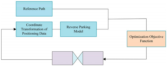
Figure 1.
NMPC Framework.
Before describing the controller design, we first provide a list of important symbols and abbreviations that will be used. Table 1 lists the parameters, and Table 2 provides the abbreviation list. In the table, N/A indicates that the symbol has no unit.

Table 1.
Parameter list.
Table 2.
Abbreviations list.
In the forward driving path tracking control system for articulated steering vehicles, the positioning system should provide the x-coordinate, y-coordinate, and heading angle of the front axle center in the global coordinate system. Additionally, it should report the longitudinal velocity and yaw rate in the front axle coordinate system, as well as the articulated angle and articulation rate at the articulation point. Figure 2 illustrates the layout of the front axle positioning system, including the positioning system, articulated angle measurement device, and articulated angle velocity measurement device.
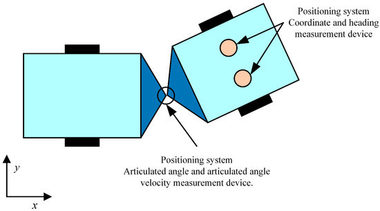
Figure 2.
Schematic diagram of the positioning system layout.
In the existing path tracking control systems for articulated steering vehicles, the positive direction of the longitudinal axis in the front axle coordinate system corresponds to the direction of the vehicle’s forward motion, with the positive direction of the lateral axis being to the left of the forward motion. Figure 3 demonstrates the positive direction of the positioning system. The positive directions of the heading angle, yaw rate, articulated angle, and articulation rate are defined as counterclockwise. The articulated angle is the difference between the heading angle of the front vehicle and that of the rear vehicle.
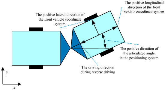
Figure 3.
Schematic diagram of the positive direction of the positioning system.
Under reverse driving conditions, the path planning system must align the reference path with the reverse driving direction of the articulated vehicle. However, at this point, the difference between the forward direction of the reference path and the heading angle provided by the positioning system is too large. Using the heading angle directly from the positioning system could cause the articulated vehicle to turn around, potentially leading to issues such as colliding with the alley wall or misaligning the work mechanism with the target object. Furthermore, during reverse driving, the original front axle effectively becomes the rear axle.
To address the issue mentioned above, the heading angle provided by the positioning system is processed as follows. First, the heading angle output by the system is defined as , and the initial value of the processing procedure is set to this heading angle:
where represents the heading angle, with the subscript denoting the positioning system. The process is then iteratively performed:
where the subscript represents the -th iteration, and the subscript denotes the reference value.
The iteration stops when the condition is met, and the actual heading angle of the rear axle is then taken as:
where represents a natural number, and the subscript denotes the actual rear axle. Since the forward direction is reversed, the positioning system must also reverse the longitudinal velocity and articulation angle:
where represents the longitudinal velocity, and denotes the articulated angle.
Considering the reverse operation of the articulated steering vehicle, the longitudinal velocity provided by the positioning system is negative. Therefore, during the computation of the path tracking control algorithm, the longitudinal velocity is a positive value by inverting the variable as shown in (4).
Under reverse driving conditions, the original front axle effectively becomes the rear axle. As a result, the kinematic model of the articulated steering vehicle must be re-derived. The theoretical foundation is derived from existing research [15]. That is, the motion relationship between the front and rear axles of the articulated steering vehicle:
where represents the distance from the axle to the articulation point, represents values associated with the front axle, and represents values associated with the rear axle. In the above expression, the distances from the front and rear axles to the articulation point are, in fact, the actual distances from the front and rear axles to the articulation point.
Considering that the control point corresponds to the actual rear axle, let represent the model output. We can obtain the following expression:
Let the center of the rear axle be the control point, leading to the following expression:
Since the original front axle effectively becomes the rear axle, and the original rear axle effectively becomes the front axle:
where the subscript represents the original front axle, and the subscript represents the original rear axle.
Figure 4 is the schematic diagram of parameter transformation.
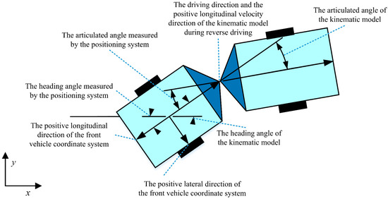
Figure 4.
Schematic diagram of parameter transformation.
By comparing Figure 4 and Figure 3, it is evident that the front axle on the right side of Figure 4 corresponds to the rear axle on the left side of Figure 3. In reverse driving, the original front axle becomes the rear axle, and the original rear axle becomes the front axle. Based on this reversal, the articulated-steering model must be re-derived. As shown in Figure 4, the axle equipped with the localization system (i.e., the original front axle, now the rear axle) is adopted as the control point, and a rear-axle-centered kinematic model is established. This transformation ensures that all kinematic analyses and control-strategy designs are referenced to the rear axle, thereby aligning the reverse-driving kinematic model with the actual motion characteristics of the articulated mining vehicle and enabling the path tracking controller to accommodate reverse operation more effectively.
Since the above model is critically stable, the control algorithm must employ an NMPC with multiple preview points [15]. Based on this control method, substituting the above articulated steering vehicle model results in the following abstracted form of the model:
among them
By discretizing the model using the Euler method, the predictive model is obtained:
Here, represents the actual time, denotes the -th iteration at that time, is the iteration period, is the control horizon, and is the prediction horizon.
Specifically:
Substitute the predicted values obtained from the predictive model into the following cost function:
Here, represents the weight matrix:
After solving the nonlinear model predictive control, the obtained articulation rate is inverted and passed to the controlled articulated vehicle to achieve reverse path tracking control. Specifically, the actual longitudinal velocity of the articulated vehicle is also set to a negative value, enabling reverse driving.
3. Simulation Results
The EMAV is a large vehicle that operates under highly demanding experimental conditions, prompting many recent studies to rely on computer simulations for the initial validation of proposed control strategies [5,15,17,19,21]. The proposed NMPC controller was tested using MATLAB R2024a (24.1.0.2537033), installed on a ROG Strix G513QY-G513QY laptop (ASUSTEK Computer Inc., Taipei, China). The central processing unit (CPU) of that computer is the AMD Ryzen 9 5900HX with Radeon Graphics, operating at 3.30 GHz. The control period for the simulation system is set to 50 ms. We evaluate the performance of the proposed controller against four distinct control strategies: (1) an NMPC for forward driving; (2) a front-axle-model-based NMPC for reverse driving; (3) an LMPC for reverse driving; and (4) the Stanley controller. The parameters for each controller are manually tuned to achieve optimal performance. Specifically, the parameterization of the proposed method is as follows. In simulation, recognizing that the prediction horizon has a comparatively minor impact on real-time load, whereas the control horizon directly determines the number of decision variables and active constraints—and therefore has a stronger influence on computational burden [24]; the prediction horizon is set to 100 and the control horizon to 2. Moreover, when the weights on the heading-error and smoothness-penalty terms are chosen to be much larger than those on the displacement error, stability and smoothness can be better preserved, but residual errors during straight-line travel may not be fully eliminated [25]. Accordingly, to balance accuracy and smoothness, , , and are all set to 1, while is set to 0. The simulation results are divided into three sets. The first two sets evaluate the performance of the proposed NMPC at various speeds and compare it with other control methods. The third set focuses on evaluating the performance of the proposed NMPC across various scenarios.
Before presenting the simulation results, it is essential to define the failure criteria. Since MAVs typically operate in confined environments, such as underground tunnels, where deviations from the reference path can pose safety risks, previous studies [26,27] have shown that a lateral error exceeding 1 m is likely to result in hazardous situations. Therefore, failure is defined as occurring when the lateral error exceeds 1 m. In such cases, the control is considered unsuccessful, and the simulation is terminated.
3.1. Simulation at a Speed of 2 m/s
In this simulation, the performance of the proposed NMPC for reverse driving (NMPC for RD) was evaluated at a speed of 2 m/s and compared with that of four other control strategies, including NMPC for forward driving (NMPC for FD), NMPC for reverse driving based on the front axle model (NMPC for RD using FAM), linear MPC for reverse driving (LMPC for RD), and the Stanley controller. The reference trajectory was designed as a U-shaped path consisting of straight segments and circular arcs with a radius of 30 m. As shown in Figure 5, the reference path and trajectory tracking results demonstrate that only the proposed NMPC scheme successfully followed the desired trajectory, while all other control methods failed to track the path effectively.
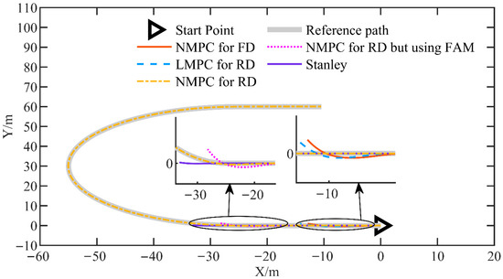
Figure 5.
The reference path and tracking results for the simulation at a speed of 2 m/s.
Figure 6 illustrates the displacement error, defined as the distance between the center of the rear axle and the reference path. The proposed reverse-driving NMPC maintains this error within a range of −0.025 m to 0.101 m, with a mean of 0.037 m and a maximum absolute error of 0.101 m. By contrast, the displacement errors of the other control methods grow progressively. These results indicate that only the proposed reverse-driving NMPC achieves high-accuracy path tracking.
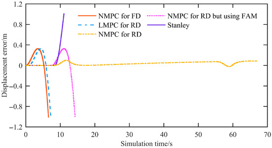
Figure 6.
The displacement error of the simulation at a speed of 2 m/s.
Figure 7 shows the heading error, defined as the angle between the rear axle’s direction of travel and the reference path. For the proposed reverse-driving NMPC, the mean heading error is negligible, and the maximum heading error is 0.028 rad. In contrast, the other controllers exhibit progressively divergent behavior. Because the forward driving NMPC (NMPC-FD) is designed for forward motion and its output is sign-inverted for reverse operation, the heading error of NMPC-FD appears in the −3 to −4 rad range in this reverse test. Taken together, apart from the reverse-driving NMPC, the LMPC, Stanley, and forward driving NMPC controllers all become unstable under reverse operation—reflecting instability rather than merely reduced accuracy.
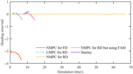
Figure 7.
The heading error of the simulation at a speed of 2 m/s.
Figure 8 presents the articulated angle. The proposed reverse-driving NMPC keeps the articulated angle within the system constraints, and its rate of change does not exceed the articulated angle rate limit. The forward driving NMPC and other MPC-based methods also stay within the bounds; however, both the articulated angle and its rate of change operate at the boundary of the angle and rate constraints, indicating a loss of stability. With Stanley control, the rate of change in the articulated angle shows steep slopes and clearly violates the articulated angle rate constraint.
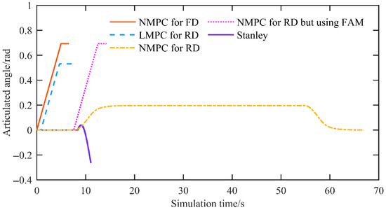
Figure 8.
The articulated angle of the simulation at a speed of 2 m/s.
Figure 9 reports the real-time metric, i.e., the controller’s computation time per control period. The maximum computation time is typically considered the most critical metric, as it determines whether the controller can deliver a control input for that cycle. If it exceeds the control period, the controller cannot provide a control input, which may lead to control failure. Simulation results show that the proposed NMPC attains an average computation time of 0.0035 s and a maximum of 0.0065 s, satisfactorily meeting the real-time requirement of the control period. In terms of real-time feasibility, the solver’s iteration count is also an important indicator. For the proposed reverse-driving NMPC, the solver requires, on average, 4.94 iterations, with a worst-case scenario of 7 iterations, indicating that, in the current implementation, the solver’s convergence cost is stable and bounded.
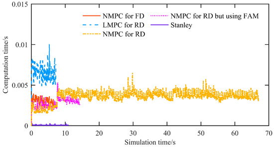
Figure 9.
The computation time of the simulation at a speed of 2 m/s.
Moreover, according to [24], increasing the control period can further alleviate real-time pressure but degrade tracking accuracy. Upgrading the controller hardware can further improve real-time performance, but it also increases system cost. Although these possibilities are not the focus of this study, they may be integrated with the research presented here in future work.
Additionally, it is noteworthy that, in simulation, the LMPC’s computation time exceeded that of the NMPC—contrary to conventional expectations. This phenomenon is related to model nonconvexities: under reverse driving, the linearization may induce pronounced nonconvexities, thereby increasing computation time.
3.2. Simulation at a Speed of 3 m/s
In this simulation, we evaluated the performance of the proposed NMPC (NMPC for RD) at a speed of 3 m/s and compared it with four control strategies: NMPC for forward driving, NMPC for reverse driving based on the front-axle model, LMPC for reverse driving, and the Stanley controller. The reference trajectory was designed as a U-shaped curve composed of straight sections and circular arcs with a radius of 30 m. As shown in Figure 10, the reference path and tracking results indicate that only the proposed NMPC is capable of successfully following the desired trajectory. All the other control methods failed to achieve successful control.
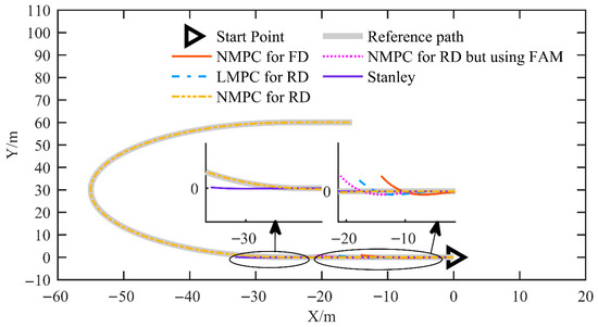
Figure 10.
The reference path and tracking results for the simulation at a speed of 3 m/s.
Figure 11 shows the displacement error. The proposed NMPC achieves a mean displacement error of 0.0175 m and a maximum displacement error of 0.0743 m. In contrast, all other control methods exhibit divergent behavior.
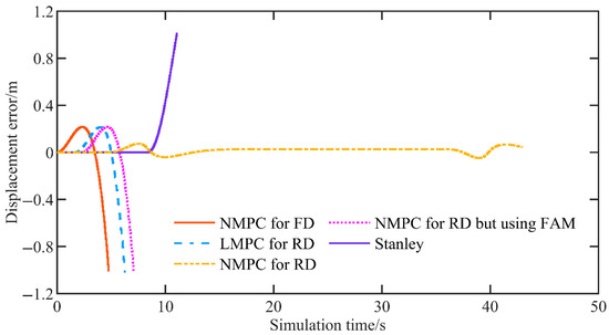
Figure 11.
The displacement error of the simulation at a speed of 3 m/s.
Figure 12 shows the heading error. For the proposed NMPC, the mean heading error is 0.000349 rad and the maximum heading error is 0.0372 rad, whereas all other control methods diverge.
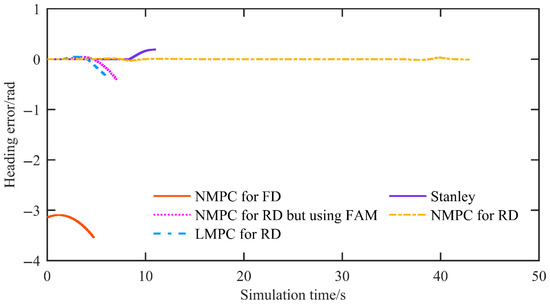
Figure 12.
The heading error of the simulation at a speed of 3 m/s.
Figure 13 shows the articulated angle. The proposed reverse driving NMPC keeps the articulated angle within the system constraints, and its rate of change does not exceed the articulated angle rate limit. The forward driving NMPC and other MPC-based methods also remain within the bounds. However, both the articulated angle and its rate of change operate at the boundary of the angle and rate constraints, indicating a loss of stability. With Stanley control, the rate of change in the articulated angle exhibits steep slopes and clearly violates the articulated angle rate constraint.
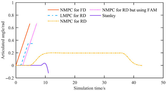
Figure 13.
The articulated angle of the simulation at a speed of 3 m/s.
Figure 14 shows the controller computation time per control period. For the proposed NMPC, the average and maximum solver times are 0.0036 s and 0.0059 s, respectively, satisfactorily meeting the real-time requirements of the control period.
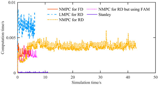
Figure 14.
The computation time of the simulation at a speed of 3 m/s.
3.3. Simulation Under Different Scenarios
In this set of simulations, we tested the proposed NMPC at a speed of 3 m/s in U-shaped curves with radii of 20 m (NMPC for RD R-20), 25 m (NMPC for RD R-25), and 30 m (NMPC for RD R-30). Figure 15 illustrates the reference path corresponding to U-shaped curves with different radii, as well as the path tracking results obtained using the proposed NMPC. It is evident that, regardless of the radius of the U-shaped curve, the proposed NMPC is capable of accurately tracking the reference path.
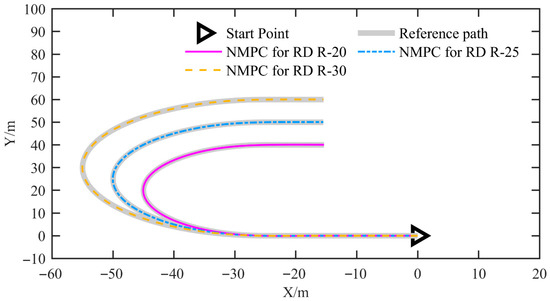
Figure 15.
The reference path and tracking results for the simulation under different scenarios.
Figure 16 shows the displacement error. For NMPC for RD R-30, NMPC for RD R-25, and NMPC for RD R-20, the mean displacement errors are 0.017 m, 0.019 m, and 0.021 m, and the maximum amplitudes are 0.074 m, 0.089 m, and 0.112 m, respectively. It is evident that, as the curvature of the U-shaped curve increases (i.e., as the radius decreases), both the mean and maximum displacement errors increase. Of course, the increase is minimal.
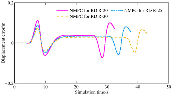
Figure 16.
The displacement error of the simulation under different scenarios.
Figure 17 shows the heading error. For the three cases above, the mean heading errors are 0.000347 rad, 0.000484 rad, and 0.000688 rad, and the maximum amplitudes are 0.0372 rad, 0.0447 rad, and 0.0565 rad, respectively. Likewise, as the curvature of the U-shaped curve increases, both the mean and maximum heading errors increase. Of course, the increase is minimal.
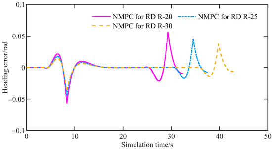
Figure 17.
The heading error of the simulation under different scenarios.
Figure 18 shows the articulated angle. The articulated angles generated by all controllers remain within the system constraints, and their rates of change do not exceed the articulated angle rate constraint.
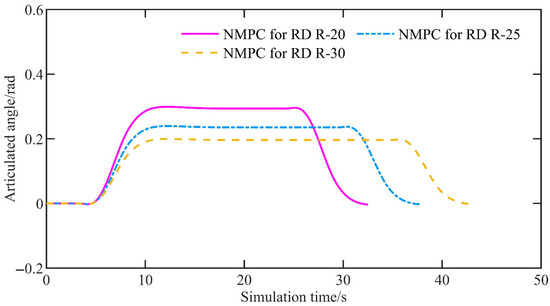
Figure 18.
The articulated angle of the simulation under different scenarios.
Figure 19 shows the controller computation time per control period. For NMPC for RD R-30, NMPC for RD R-25, and NMPC for RD R-20, the average computation times are 0.0036 s, 0.0037 s, and 0.0037 s, while the maximum computation times are 0.0060 s, 0.0058 s, and 0.0060 s, respectively. The results demonstrate that the computation time remains relatively stable as the curvature of the U-shaped curve increases. Furthermore, the average solver iteration counts are 4.97, 5.03, and 5.22, with worst-case iteration counts of 7, 9, and 9, respectively.
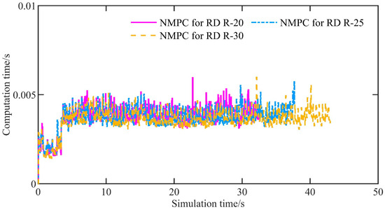
Figure 19.
The computation time of the simulation under different scenarios.
4. Conclusions and Perspectives
This paper proposes a nonlinear model predictive control (NMPC) method for path tracking during the reverse motion of articulated mining vehicles and equipment. This method does not require additional positioning equipment and, compared with existing approaches, is better adapted to the conditions of reverse driving. Conventional control methods, including standard NMPC, are primarily designed for forward driving scenarios and typically use the front-axle center as the control point, rendering them unsuitable for reverse operation. By contrast, the method presented in this chapter is tailored to reverse maneuvers of articulated mining vehicles and equipment, selecting the rear axle as the control point. In addition, we systematically reformulate the kinematic model for reverse operation, explicitly defining the sign conventions for key variables—heading angle, longitudinal velocity, and articulation angle—and the treatment of reference coordinate frames to ensure consistency between the model and the vehicle’s motion. Relative to existing methods, the proposed approach achieves higher accuracy in reverse driving. Through a comparative analysis with existing models, such as NMPC for forward driving, NMPC for reverse driving using the front axle model, and LMPC for reverse driving, the following conclusions are drawn:
Firstly, the proposed NMPC demonstrates outstanding control accuracy and real-time performance. In terms of control accuracy, the displacement error amplitude does not exceed 0.101 m, and the heading error amplitude does not exceed 0.0372 rad. Regarding real-time performance, the maximum solution time per control period is no more than 0.007 s.
Secondly, the proposed NMPC method can better adapt to reverse driving conditions compared to other methods. Simulation results indicate that other control methods are ineffective in adapting to reverse driving conditions during path tracking. At the same time, the proposed NMPC successfully addresses this issue, better adapting to the reverse driving conditions and maintaining high control accuracy during reverse path tracking.
Thirdly, the proposed NMPC method ensures both control accuracy and real-time performance, even as the reverse path becomes more complex, with no significant degradation in performance. For example, as the radius of the U-shaped curve decreases from 30 m to 25 m and then to 20 m, the maximum values of displacement error amplitude increase only from 0.074 m to 0.089 m and subsequently to 0.112 m.
Simulation validation demonstrates that the proposed method maintains high-precision real-time control under various operational conditions. The EMAV is a large vehicle that operates under extremely demanding experimental conditions, which is why we have not yet conducted experiments on the actual vehicle. We have currently deployed the system in the ROS (Robot Operating System), but we have only conducted simulations in Gazebo. Since Gazebo simulations and MATLAB simulations are of the same level, the results are broadly consistent. Including both in the paper would be redundant and would not provide additional insights. Accordingly, the Gazebo simulation results are not presented in the main text. However, the deployment in ROS will help us conduct further prototype experiments in the near future. We are currently developing a small-scale unmanned EMAV prototype. Additionally, with the emergence of new high-fidelity simulation tools, we are considering incorporating these tools into our future work to further validate the proposed approach.
The proposed NMPC also has limitations and potential failure modes. The principal limitations concern real-time performance and the cost of industrial deployment. Its real-time capability is relatively weak, necessitating reliance on high-performance computing platforms for practical implementation and potentially rendering deployment prohibitively expensive in industrial settings. A potential failure mode arises when the vehicle speed is excessively high and the required steering exceeds the steering mechanism’s constraints on articulation angle or on the rate of change in the articulation angle. In such circumstances, not only the NMPC controller but virtually any controller cannot circumvent these physical limits to accomplish path tracking control.
Finally, obstacle avoidance can be achieved by introducing an obstacle avoidance penalty term into the objective function of the proposed path tracking controller. However, existing studies suggest that this strategy may significantly compromise real-time performance. Moreover, given the increasingly urgent demands for environmental sustainability [28,29], we plan to incorporate energy consumption-related performance criteria into the path tracking control in future work to enhance the environmental friendliness of the proposed approach.
Author Contributions
Conceptualization, G.B. and P.L.; methodology, G.B. and P.L.; software, G.B. and P.L.; validation, G.B. and P.L.; formal analysis, G.B. and P.L.; investigation, G.B., Y.M., P.L. and Z.L.; resources, G.B. and P.L.; data curation, G.B., F.Z. and P.L.; writing—original draft preparation, G.B. and P.L.; writing—review and editing, G.B. and P.L.; visualization, G.B. and P.L.; supervision, G.B. and P.L.; project administration, G.B. and P.L.; funding acquisition, G.B. All authors have read and agreed to the published version of the manuscript.
Funding
This research is funded by the National Key Research and Development Program of China (2023YFC3806603) and the National Natural Science Foundation of China (52202505).
Data Availability Statement
The original data presented in the study are included in the article, further inquiries can be directed to the corresponding author.
Conflicts of Interest
Author G.B. was employed by the company Tangshan Jidong Equipment Engineering Co., Ltd. The remaining authors declare that the research was conducted in the absence of any commercial or financial relationships that could be construed as a potential conflict of interest.
References
- Bai, G.X.; Luo, W.D.; Liu, L.; Meng, Y.; Gu, Q.; Li, K.L. Current status and progress of path tracking control of mining articulated vehicles. Chin. J. Eng. 2021, 43, 193–204. (In Chinese) [Google Scholar]
- Zhao, X.; Yang, J.; Zhang, W.M.; Zeng, J. Feedback linearization control for path tracking of articulated dump truck. Telkomnika 2015, 13, 922–929. [Google Scholar] [CrossRef][Green Version]
- Sasiadek, J.Z.; Lu, Y. Path tracking of an autonomous LHD articulated vehicle. IFAC Proc. 2005, 38, 55–60. [Google Scholar] [CrossRef]
- Alshaer, B.J.; Darabseh, T.T.; Momani, A.Q. Modelling and control of an autonomous articulated mining vehicle navigating a predefined path. Int. J. Heavy Veh. Syst. 2014, 21, 152–167. [Google Scholar] [CrossRef]
- Cui, D.; Wang, G.; Zhao, H.; Wang, S. Research on a path-tracking control system for articulated tracked vehicles. Stroj. Vestn.-J. Mech. Eng. 2020, 65, 311–325. [Google Scholar] [CrossRef]
- Zhao, X.; Yang, J.; Zhang, W.M.; Zeng, J. Sliding mode control algorithm for path tracking of articulated dump truck. Trans. CSAE 2015, 31, 198–203. (In Chinese) [Google Scholar]
- Nayl, T.; Nikolakopoulos, G.; Gustafsson, T.; Kominiak, D.; Nyberg, R. Design and experimental evaluation of a novel sliding mode controller for an articulated vehicle. Robot. Auton. Syst. 2018, 103, 213–221. [Google Scholar] [CrossRef]
- Zhong, S.; Peng, D.; Huang, B.; Ma, L.T. Path-tracking ability of the ASV on different adhesion coefficient roads based on slide mode control. Electronics 2023, 13, 105. [Google Scholar] [CrossRef]
- Li, R.; Li, L.; Zhang, T.; Sun, Z.; Ma, K. Optimization Study of Trajectory Tracking Algorithm for Articulated Vehicles Based on Adaptive Sliding Mode Control. World Electr. Veh. J. 2025, 16, 114. [Google Scholar] [CrossRef]
- Wang, Y.; Liu, X.; Ren, Z.; Yao, Z.; Tan, X. Synchronized path planning and tracking for front and rear axles in articulated wheel loaders. Autom. Constr. 2024, 165, 105538. [Google Scholar] [CrossRef]
- Shao, J.K.; Zhao, X.; Yang, J.; Zhang, W.M.; Kang, Y.T.; Zhao, X.X. Reinforcement learning algorithm for path tracking control of articulated vehicle. Trans. Chin. Soc. Agric. Mach. 2017, 48, 376–382. (In Chinese) [Google Scholar]
- Dekker, L.G.; Marshall, J.A.; Larsson, J. Experiments in feedback linearized iterative learning-based path tracking for center-articulated industrial vehicles. J. Field Robot. 2019, 36, 955–972. [Google Scholar] [CrossRef]
- Chen, X.; Yang, C.; Cheng, J.; Hu, H.; Shao, G.; Gao, Y.; Zhu, Q. A novel iterative learning-model predictive control algorithm for accurate path tracking of articulated steering vehicles. IEEE Robot. Autom. Lett. 2024, 9, 7373–7380. [Google Scholar] [CrossRef]
- Nayl, T.; Nikolakopoulos, G.; Gustafsson, T. A full error dynamics switching modeling and control scheme for an articulated vehicle. Int. J. Control Autom. 2015, 13, 1221–1232. [Google Scholar] [CrossRef]
- Bai, G.X.; Liu, L.; Meng, Y.; Luo, W.D.; Gu, Q.; Ma, B.Q. Path tracking of mining vehicles based on nonlinear model predictive control. Appl. Sci. 2019, 9, 1372. [Google Scholar] [CrossRef]
- Huang, B.; Yuan, Z.J.; Peng, D.Z.; Wei, X.X.; Wang, Y.S. Coordination control of active steering and direct yaw control for the articulated steering vehicle. Shock Vib. 2023, 2023, 5577119. [Google Scholar] [CrossRef]
- Jeong, Y. Integrated vehicle controller for path tracking with rollover prevention of autonomous articulated electric vehicle based on model predictive control. Actuators 2023, 12, 41. [Google Scholar] [CrossRef]
- Zhou, B.C.; Su, X.; Yu, H.J.; Guo, W.T.; Zhang, Q. Research on path tracking of articulated steering tractor based on modified model predictive control. Agriculture 2023, 13, 871. [Google Scholar] [CrossRef]
- Hu, K.; Cheng, K. Trajectory planning for an articulated tracked vehicle and tracking the trajectory via an adaptive model predictive control. Electronics 2023, 12, 1988. [Google Scholar] [CrossRef]
- Sun, N.; Zhang, W.; Yang, J. Integrated path tracking controller of underground articulated vehicle based on nonlinear model predictive control. Appl. Sci. 2023, 13, 5340. [Google Scholar] [CrossRef]
- Lee, T.; Jeong, Y. A tube-based model predictive control for path tracking of autonomous articulated vehicle. Actuators 2024, 13, 164. [Google Scholar] [CrossRef]
- Qi, Z.; Gu, Q.; Meng, Y.; Bai, G.; Ding, D. The load-haul-dump operation cycle recognition based on multi-sensor feature selection and bidirectional long short-term memory network. Meas. Control 2023, 56, 1523–1533. [Google Scholar] [CrossRef]
- Wang, Z.Q.; Yang, Z.H.; Zhao, X.Y.; Yan, B.; Wang, B.J. Control algorithm design and test analysis of the autonomous loading process of underground LHDs. Nonferrous Metall. Equip. 2022, 36, 26–31. [Google Scholar]
- Bai, G.; Liu, L.; Meng, Y.; Liu, S.; Liu, L.; Liu, W. Real-time Path Tracking of Mobile Robot Based on Nonlinear Model Predictive Control. Trans. Chin. Soc. Agric. Mach. 2020, 51, 47–52. [Google Scholar]
- Bai, G.; Liu, S.; Meng, Y.; Liu, L.; Gu, Q.; Wang, Z. Selection of reference points for path tracking control based on rolling prediction. In Proceedings of the 2024 39th Youth Academic Annual Conference of Chinese Association of Automation (YAC), Dalian, China, 7–9 June 2024; pp. 1626–1630. [Google Scholar]
- Zhu, Q.Y.; Chen, H.Y.; Yi, J.; Wen, C.; Hu, O. Modelling of stable angle-based instability threat indicator for articulated off-road vehicles. Int. J. Comput. Appl. Technol. 2014, 49, 316–324. [Google Scholar] [CrossRef]
- Li, D.Y.; Yang, C.J.; Lu, Y.; Zhou, W.Q.; Zhang, W.H. Research on Trajectory-Tracking Control of the Virtual Rail Train with Considering Hinge Forces Between the Vehicles. J. Dyn. Control 2025, 23, 69–79. [Google Scholar]
- Hassan, S.S.M.; Mohamed, N.R.G.; Saad, M.M.A.; Salem, A.M.; Ibrahim, Y.H.; Elshakour, A.A.; Fathy, M.A. A novel non-woven fabric sandwich filter with activated carbon/polypyrrole nanocomposite for the removal of CO, SO2 and NOx emitted from gasoline engines. Fuel 2025, 401, 135838. [Google Scholar] [CrossRef]
- Hassan, S.S.M.; Mohamed, N.R.G.; Saad, M.M.A.; Ibrahim, Y.H.; Elshakour, A.A.; Fathy, M.A. Eco-Friendly Removal and IoT-Based Monitoring of CO2 Emissions Released from Gasoline Engines Using a Novel Compact Nomex/Activated Carbon Sandwich Filter. Polymers 2025, 17, 1447. [Google Scholar] [CrossRef]


Disclaimer/Publisher’s Note: The statements, opinions and data contained in all publications are solely those of the individual author(s) and contributor(s) and not of MDPI and/or the editor(s). MDPI and/or the editor(s) disclaim responsibility for any injury to people or property resulting from any ideas, methods, instructions or products referred to in the content. |
© 2025 by the authors. Published by MDPI on behalf of the World Electric Vehicle Association. Licensee MDPI, Basel, Switzerland. This article is an open access article distributed under the terms and conditions of the Creative Commons Attribution (CC BY) license (https://creativecommons.org/licenses/by/4.0/).