Abstract
High-precision speed measurement at low speeds in PMSM drives is hindered by encoder quantization noise. This paper proposes an enhanced extended state observer (ESO)-based method to overcome limitations of conventional approaches such as direct differentiation with the low-pass filter (high noise), the phase-locked loop (PLL)-based method (limited dynamic response), and standard ESO (sensitivity to disturbance). The improved ESO incorporates reference torque feedforward and disturbance feedback, significantly suppressing noise and enhancing robustness. Simulations and experiments demonstrate that the proposed method reduces steady-state speed fluctuation by up to 42% compared to standard ESO and over 90.1% relative to differentiation-based methods, while also improving transient performance. It exhibits superior accuracy and stability across various low-speed conditions, offering a practical solution for high-performance servo applications.
1. Introduction
Permanent magnet synchronous motors (PMSMs) have been widely used in low-speed high-precision control applications such as robot joints, precision machine tools, and navigation systems due to their advantages such as brushless structure, high torque density, and excellent speed regulation performance [1,2]. Furthermore, with the rapid advancement of the automotive industry towards intelligent driving, the demand for high-precision navigation and positioning systems has become increasingly critical [3]. The accuracy of satellite-based navigation, a cornerstone for autonomous vehicle guidance, is fundamentally linked to the performance of its attitude control system—particularly the control moment gyroscope (CMG) frame servo motors [4]. These PMSMs, operating at ultra-low speeds, are responsible for precise satellite attitude adjustments [5]. Any speed fluctuation or quantization-induced noise in these motors directly translates to pointing errors of the satellite platform, thereby degrading the quality and ultimate accuracy of the navigation signals received by ground vehicles [6]. This creates a direct technological pathway through which advancements in low-speed PMSM control can enhance the performance of intelligent transportation systems. Furthermore, high-precision steering servo control is of paramount importance for enhancing vehicle handling stability and driving safety. This is particularly critical in low-speed application scenarios of electric vehicles (EVs)—such as autonomous parking, traffic jam assist, and Electric Power Steering (EPS)—where more stringent demands are imposed on the system’s disturbance rejection capability, response speed, and steady-state accuracy [7]. For servo systems with high control accuracy requirements, precise rotor position detection is crucial for speed control and coordinate transformation, directly determining the system’s control performance [8].
In high-precision speed measurement applications, position signals are typically obtained from encoders, including incremental encoders, rotary transformers, absolute encoders, and hybrid encoders [9]. Incremental encoders are cost-effective and generate A/B phase pulse signals, but are susceptible to noise and cumulative error. Rotary transformers offer high accuracy but are bulky and require additional decoding circuitry, increasing cost and complexity [10]. Absolute encoders provide robust anti-interference and positioning capabilities by outputting binary codes of the rotor’s absolute position, making them suitable for high-precision applications such as mechanical equipment [11]. However, their high cost and physical size increase with resolution, limiting their use in space-constrained applications [12].
In low-speed high-precision applications, the PMSM rotor may operate at extremely low speeds, leading to encoder quantization errors and low-speed creeping due to delayed signal updates [13]. This lag in speed feedback severely degrades system performance, necessitating advanced speed estimation techniques beyond traditional methods. Conventional speed measurement methods, such as the M/T method, suffer from significant delays and pulse loss at low speeds, especially near critical velocity [14]. The constant elapsed time method improves upon this but still has a minimum measurable speed limitation [15]. To overcome these issues, various model-based and observer-based techniques have been proposed. Numerical differentiation with low-pass filtering is simple but amplifies high-frequency noise and introduces phase lag, compromising dynamic response [16]. Phase-locked loop (PLL)-based methods offer improved noise immunity but exhibit limited dynamic performance during transients [17]. State observers, such as Luenberger and sliding mode observers, provide model-based estimates but are sensitive to parameter variations and disturbances [18,19]. Kalman filters (KF) and extended Kalman filters (EKF) are widely used for their optimal noise handling capabilities [20,21], but their performance depends heavily on model accuracy and computational resources [8]. Recent advances include nonlinear observers [22], adaptive observers [23,24], and neural network-based estimators [25], which improve robustness and accuracy under varying conditions. However, these methods often require complex tuning and may not fully address the trade-off between noise suppression and dynamic response in ultra-low-speed regimes. Extended State Observers (ESOs) have gained attention for their ability to estimate both system states and lumped disturbances [26,27]. Standard ESOs, however, are sensitive to model uncertainties and exhibit limited robustness in practical applications [28].
Despite these advancements, a significant research gap remains in achieving high precision, excellent dynamic response, and strong robustness against disturbances in ultra-low-speed PMSM drives, where conventional methods are inadequate. Although advanced ESOs like the one by Hou et al. [22] perform well at medium-to-high speeds, they are not optimized for the distinct challenges of the ultra-low speed regime (below 2 rpm), where encoder quantization and nonlinear disturbances dominate. To address this, the present work proposes an improved ESO that integrates reference torque feedforward and active disturbance feedback. This structure is specifically tailored to enhance noise suppression and dynamic response under such demanding conditions, thereby bridging a critical gap in high-precision servo applications.
To bridge this gap, this paper proposes an improved third-order ESO structure incorporating reference torque feedforward and active disturbance feedback. This design effectively decouples disturbance estimation from the current loop, enhancing robustness and noise immunity. Simulations and experimental results demonstrate that the proposed method significantly reduces speed fluctuations and improves transient response, offering a superior solution for high-performance servo applications.
2. Basis of Low-Speed Speed Measurement Problem
2.1. Speed Measurement Error Analysis in Low-Speed Operation
Depicted in Figure 1 is a conventional control block diagram for permanent magnet synchronous motors (PMSMs) operating at low speeds with high precision. The system is based on a dual closed-loop vector control framework, which consists of an inner current loop and an outer speed loop. The outer speed loop is realized by a speed controller and a speed measurement module. As shown in Figure 1, , and correspond to the reference speed, d-axis reference current, and q-axis reference current, respectively.
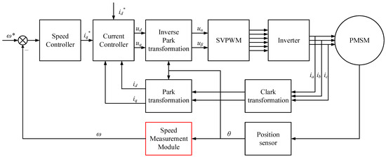
Figure 1.
Field-Oriented Control (FOC) for PMSM with Cascaded Loops (Speed and Current Control Loops).
In low-speed high-inertia servo systems, quantization errors primarily arise from two sources: first, the quantized output of angular measurement devices, and second, the A/D and D/A conversion processes during signal acquisition and control command output in digital controllers. During low-speed motor operation, the error caused by the former is significantly more pronounced than the latter. Therefore, the following analysis focuses on the error generation mechanism of the former.
In the control loop, the encoder has a fixed resolution (Res), and its output angular signal is not continuous but rather a stepwise signal with the resolution as the minimum incremental change. There exists an error (∆θ) between the output angle and the actual angle, with a maximum value of ∆θmax = Res. Consequently, when this angular signal is utilized in coordinate transformation algorithms, it introduces corresponding quantization errors, as illustrated in Figure 2.
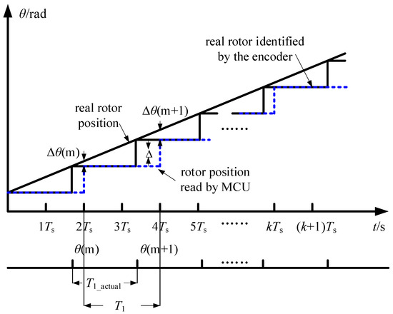
Figure 2.
Illustration of Encoder Quantization Error.
Denoting the electrical angle of the motor as θe = pnθ, the transformation relationship for the Clark & Park transformation is as follows:
Among them, Id and Iq represent the direct-axis and quadrature-axis currents, while Ia, Ib, and Ic represent the currents of the three-phase stator windings.
Considering the position signal error ∆θ and denoting the electrical angle error as ∆θe = pn∆θ, we obtain
Let the currents in the d and q axes affected by the angle measurement error be denoted as Id and Iq, respectively. Then, we can obtain the following:
The inverse-Park transformation converts the voltage references from the rotating dq-frame back to the stationary αβ-frame, utilizing the rotor position angle θe. This process is equally susceptible to the quantization error Δθe present in the measured position signal. The ideal transformation is given by the following:
However, when the transformation is executed with the measured angle θe + Δθe denoted as , the actual implemented transformation becomes as follows:
Following a derivation analogous to Equation (2), the erroneous output voltages can be related to the ideal voltages through a rotation matrix dependent on the angular error Δθe:
As can be seen from Equations (4) and (6), the error caused by the quantization of the position signal affects the feedback current value and voltage control quantity in the controller, causing them to deviate from the ideal values and limiting the control accuracy of the system. This error can be improved by using a high-resolution encoder or by numerically compensating for the quantized signal using numerical processing.
2.2. Direct Differentiation Method with Low-Pass Filter
For absolute encoders, the most common speed measurement method involves directly differentiating the rotor position (implemented in microcontrollers as the difference between rotor positions at adjacent sampling instants). Due to encoder quantization and system sampling effects, the speed signal obtained through differentiation often appears as a pulse train. If such a signal is directly fed into the control system, it may introduce significant noise. Therefore, a low-pass filter is typically cascaded after the differentiated speed signal to smooth the output, and the processed signal is then used as the feedback speed to mitigate noise effects.
First, the impact of encoder quantization error on the directly differentiated speed is analyzed. As mentioned earlier, when the motor operates at low speeds, the microcontroller may sample identical positions at adjacent sampling instants. For analytical clarity, the critical speed nc is defined as the speed at which the sampled positions differ exactly between adjacent sampling instants. That is, when the motor speed exceeds nc, the sampled positions must differ between adjacent instants; otherwise, there will inevitably be instances where adjacent samples yield the same position. It follows that nc is determined by the encoder quantization error and the sampling rate of the position signal. The quantization error and critical speed corresponding to absolute encoders with different bit resolutions are presented in Table 1.

Table 1.
Quantization Error for Absolute Encoders with Different Bit Resolutions.
The inherent quantization effect, as analyzed above, directly impacts the velocity signal derived through direct differentiation. The process of differentiating the quantized position signal inherently amplifies high-frequency noise, leading to significant differential noise in the speed estimate. This noise manifests as considerable steady-state speed fluctuation, which is detrimental to high-precision control performance. Consequently, the application of a low-pass filter (LPF) is necessary to attenuate this high-frequency noise and smooth the velocity output. However, while filtering suppresses noise, it inevitably introduces phase lag. This phase delay degrades the system’s dynamic response, particularly at low speeds where timely feedback is critical for stability and performance. This fundamental trade-off between noise attenuation (via filtering) and dynamic performance preservation motivates the exploration of alternative speed estimation techniques, such as phase-locked loops and state observers, which avoid explicit differentiation.
3. Mathematical Model of Low-Speed Speed Measurement Method
3.1. Low-Speed Velocity Measurement Based on Integral-Type Phase-Locked Loop
When using the direct differentiation method based on a filter for speed measurement, the velocity signal after direct differentiation is in the form of pulses, containing high-frequency noise. Therefore, a low-pass filter is required to suppress high-frequency noise. In fact, to reduce the speed measurement noise, avoiding explicit differentiation operations is another approach. The speed measurement method based on a phase-locked loop can achieve this.
The phase-lock loop structure for speed measurement module is shown in Figure 3 below.
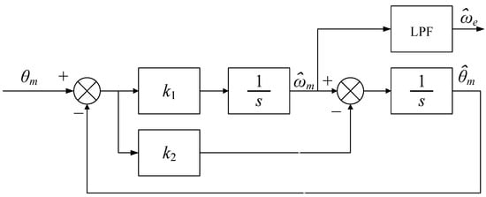
Figure 3.
Speed measurement module based on phase-lock loop.
The phase-locked loop (PLL) based speed measurement module provides robust real-time velocity estimation for motor control applications. The system processes encoder or tachometer signals through conditioning circuitry before the phase detector compares them with the VCO feedback signal, generating a speed-proportional error signal. A carefully designed loop filter processes this error to ensure stable locking characteristics while rejecting high-frequency noise, with the filtered output driving the VCO to complete the control loop.
This architecture offers significant advantages for motor control systems, particularly its inherent noise immunity and dynamic tracking capability. The PLL’s ability to maintain precise speed measurement during acceleration/deceleration makes it ideal for servo applications, while the analog front-end combined with digital processing ensures both accuracy and implementation flexibility. The optional frequency divider extends its utility for different encoder resolutions and speed ranges, making this solution particularly versatile for industrial drive systems.
3.2. ESO-Based Low-Speed Velocity Estimation Using Third-Order Observer
3.2.1. Speed Measurement Module Based on State Observer
The speed measurement method based on the observer is a model-based method. First, assume that the servo system is an ideal system, ignore the disturbances, and according to the motor motion equation.
Let b = Kt/J, and take the position signal as the system output. Then, the system equation of state and the output equation are as follows:
Based on the state Equation (8), assuming that the model parameters such as the viscous friction B of the system and the system inertia J are known, the following velocity measurement state observer can be designed.
In the formula, the estimated rotor position and estimated rotational speed output by the observer are shown.
Let the state estimation error . Combining Equations (9) and (10), the error equation can be obtained as follows:
When L is 0, the observer is in open-loop form. If model uncertainty is not considered, Equations (10) and (11) are completely consistent. However, according to the error equation, the convergence of the error is completely determined by A. If the eigenvalues of A are all close to the origin, the convergence speed of the error is very slow, which is not conducive to subsequent control using observations. When L is not 0, the observer is in a closed-loop form, and configuring the L matrix can make the error converge at any speed. In addition, closed-loop observers can also tolerate model uncertainty to a certain extent, which is more commonly used in control system design.
When configuring the poles of the observer, the eigenvalues of A-LC are often configured in the form of multiple roots. Regarding Equation (11), if both eigenvalues are assigned at −ω0, the two coefficients of the L matrix can be calculated as follows:
The speed measurement system structure based on the above state observer is shown in Figure 4.
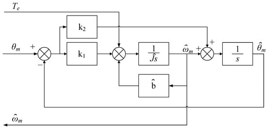
Figure 4.
Speed measurement module based on state observer.
3.2.2. Speed Measurement Module Based on Extended State Observer
In practical applications, the viscous damping coefficient B of the motor varies with different operating conditions, especially at ultra-low speeds where the friction model is complex and cannot be simply characterized by viscous damping. In addition, the presence of cogging, friction, or load disturbances can also deteriorate the observation performance of the above observer. Therefore, in practical applications, when considering the motor state equation, the form in the equation is often not used, but the damping term is included in the disturbance and the total disturbance f is expanded to a new state. At this point, the new state equation is shown below.
For Equation (13), assuming b is known, an extended state observer can be designed as follows:
Comparing the two observers corresponding to Equations (14) and (10), it can be seen that the observer represented by Equation (14) only has two model related parameters, namely KT and J, which make up b, and only appears in the E matrix. The D matrix does not contain model related parameters, which improves the robustness of the observer to model uncertainty.
Similarly, by arranging the three eigenvalues of D − LF at −ωo, the three coefficients of the L matrix can be calculated as follows: l1 = 3ωo, l2 = 3ωo2 and l3 = ωo3. Since the damping term is considered as a disturbance when using an extended state observer, the disturbance effect is taken into account here. The schematic diagram of the speed loop system is shown in Figure 5.
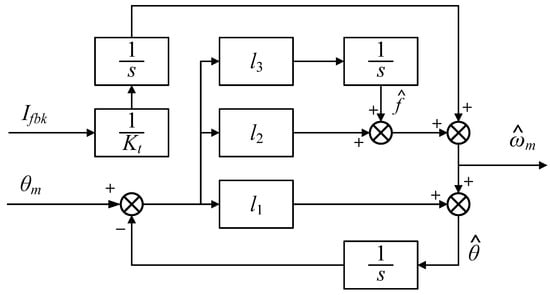
Figure 5.
Speed measurement method based on 3rd order ESO.
3.2.3. Speed Measurement Module with Disturbance Observation Output
Based on the proposed ESO-based speed measurement method, an improved ESO approach is introduced, which incorporates an additional disturbance feedback loop to suppress unmodeled disturbances originating from both the speed and current loops. The overall structure of the proposed method is illustrated in Figure 6.
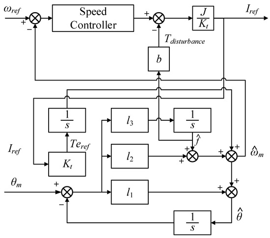
Figure 6.
Speed measurement method based on improved ESO.
As depicted in the block diagram, the system includes a speed controller that generates the reference torque command Te*. Unlike the conventional ESO method, which relies on the feedback current to estimate the torque, the proposed improved ESO utilizes the reference torque command issued by the MCU. This torque reference, along with the measured mechanical position θm, is fed into a modified ESO structure comprising multiple gain stages (l1, l2, l3) and integrative elements. The observer estimates both the angular velocity and the lumped disturbance , which encompasses unmodeled dynamics and external perturbations. The estimated disturbance is then fed back to enhance the robustness of the speed observation. The improved structure effectively reduces the noise and improves the accuracy of the speed estimation, making it more suitable for high-performance motor drive applications.
4. Simulation of Low-Speed Speed Measurement Method
Simulations were carried out under the conditions specified in Table 2. The PMSM used in this study has 24 pole pairs, which is typical for direct-drive applications requiring low speed and high precision. The simulation accounted for non-ideal factors commonly encountered in high-precision low-speed control systems, including encoder quantization error, MOSFET dead time, and shaft viscous damping.
Table 2.
The simulation parameters of the low-speed measurement test.
The simulations were performed at several reference speeds typical for servo systems: 10°/s, 6°/s, 2°/s.
To ensure a fair comparison of control performance among the different speed measurement methods, each method is evaluated by interchangeably replacing the speed measurement module in the control structure shown in Figure 1. The speed controller employs a PI regulator with a tuned bandwidth of 100 rad/s. The observer bandwidth was chosen as four times the control bandwidth, a common engineering practice that provides a robust stability margin while keeping the observer gains within implementable ranges for the digital processor. Hence, for a valid comparison without introducing additional phase lag to the speed control loop, the equivalent control bandwidth for all speed measurement methods is uniformly set to 400 rad/s. The encoder reading rate of the experimental setup is 20 kHz. The specific parameter tuning for each method is as follows. Direct Differentiation Method: The bandwidth of the low-pass filter is set to 400 rad/s. PLL Method: Based on the system control bandwidth of 400 rad/s and referring to (12), the parameters are calculated as k1 = 799.9 and k2 = 159933. The parameters tunned for observer-based methods (Original and Improved ESO) were as followed. The three observer gains are determined by the triple-pole placement strategy at a bandwidth of 400 rad/s, resulting in l1 = 3 × 400, l2 = 3 × 4002, and l3 = 4003. Moreover, for the improved ESO method, based on simulation results, the disturbance compensation gain is optimally set to 0.2.
Firstly, the reference speed was set to 10°/s and the encoder resolution was varied among 16 bit, 20 bit, and 26 bit. To evaluate the dynamic disturbance rejection and steady-state noise suppression capabilities of the different speed measurement methods, a torque disturbance of 1 Nm was applied at 0.3 s, with a duration of 0.01 s. The simulation results are presented in Figure 7, Figure 8 and Figure 9.
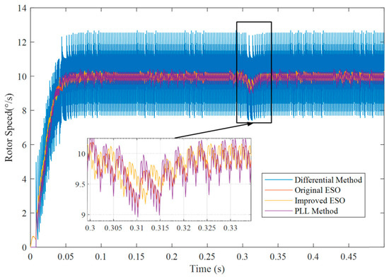
Figure 7.
Comparison of different methods for a 16-bit encoder at 10°/s reference speed.
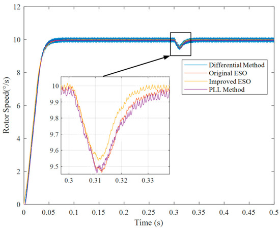
Figure 8.
Comparison of different methods for a 20-bit encoder at 10°/s reference speed.
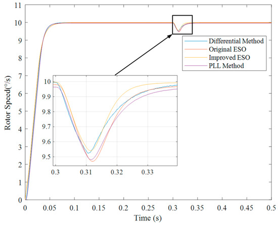
Figure 9.
Comparison of different methods for a 26-bit encoder at 10°/s reference speed.
In Figure 7, Figure 8 and Figure 9, it is illustrated that the proposed improved ESO method has the best performance among these speed measurement algorithms, including the minimum fluctuation in a steady state and the best dynamic performance when the torque suddenly changes.
Secondly, the reference speed was set to 6°/s and the encoder resolution was set to 16 bit, 20 bit, and 26 bit separately. The 1 Nm torque fluctuation was set at 0.3 s, lasting for 0.01 s. The simulation result is shown in Figure 10, Figure 11 and Figure 12.
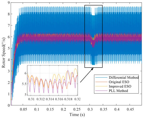
Figure 10.
Comparison of different methods for a 16-bit encoder at 6°/s reference speed.
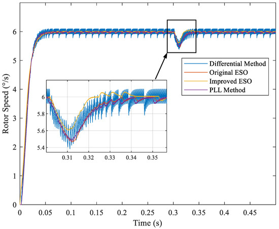
Figure 11.
Comparison of different methods for a 20-bit encoder at 6°/s reference speed.
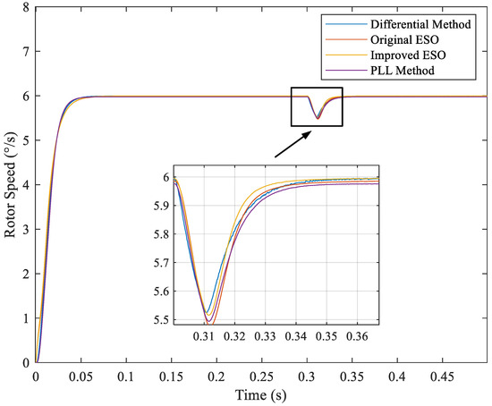
Figure 12.
Comparison of different methods for a 26-bit encoder at 6°/s reference speed.
With the reduction in reference speed, the speed fluctuations in a steady state increase. Nevertheless, the improved ESO method still outperforms the others.
Thirdly, the reference speed was set to 2°/s. In addition, all the conditions are same. The simulation result is shown in Figure 13, Figure 14 and Figure 15.
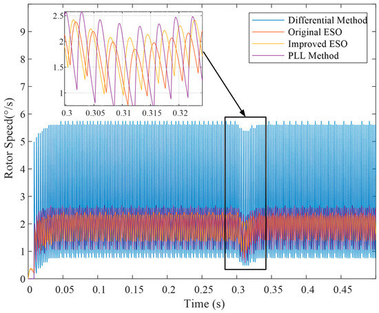
Figure 13.
Comparison of different methods for a 16-bit encoder at 2°/s reference speed.
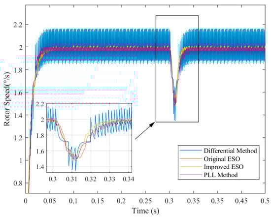
Figure 14.
Comparison of different methods for a 20-bit encoder at 2°/s reference speed.
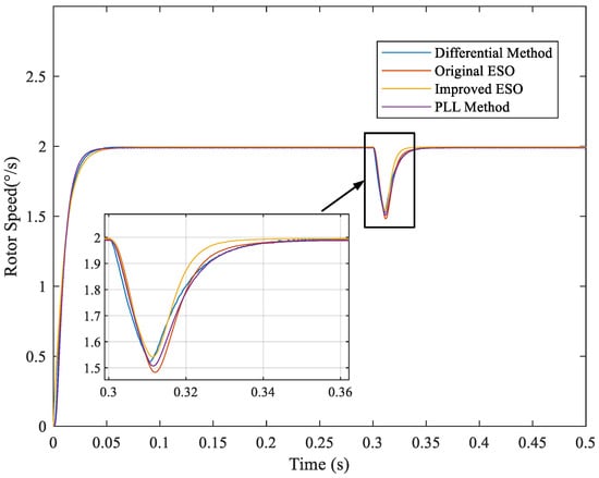
Figure 15.
Comparison of different methods for a 26-bit encoder at 2°/s reference speed.
Based on the experimental results, the speed fluctuation of each method was calculated as the difference between the actual rotational speed and the reference speed. The results are summarized in Table 3.
Table 3.
The maximum fluctuation of different speed measurement methods in a steady state.
Based on the data compiled in Table 3, the comparison chart of various speed measurement methods for the Permanent Magnet Synchronous Motor (PMSM) under low-speed conditions, as shown in Figure 16, is obtained.
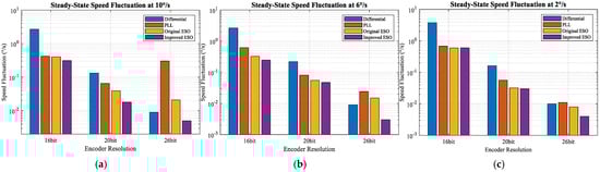
Figure 16.
Simulation Results of Speed Measurement Methods for PMSMs at Low Speeds. (a) Reference speed is 10°/s. (b) Reference speed is 6°/s. (c) Reference speed is 2°/s.
As shown in Figure 16, the proposed improved ESO method generally exhibits the smallest speed fluctuation across most test conditions, followed by the original ESO method. The differentiation-based speed estimation method, which incorporates cascaded low-pass filters, shows the largest fluctuation—especially under low encoder resolutions—due to the inherent noise amplification of the derivative operation.
5. Experiment of Low-Speed Speed Measurement Method
Experimental Setup for Low-Speed Motor Encoder Evaluation
The experimental platform used in this study is a low-speed high-inertia servo system, as illustrated in Figure 17. The system is built around an STM32F4 series microcontroller, which is widely employed in industrial control applications. Position feedback is provided by a 26-bit absolute optical encoder, which transmits binary position data to the controller via a half-duplex communication protocol.
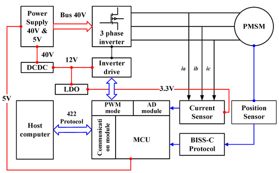
Figure 17.
The hardware structure of experiment.
Power is supplied through a 40 V and 5 V DC-DC converter. A three-phase inverter, driven by PWM signals from the microcontroller, is used to power the motor. Current sensing and position feedback are implemented via dedicated sensors, with communication supported by the BISS-C protocol. An onboard communication module enables data exchange with a host computer.
The physical experimental setup is shown in Figure 18. A host computer is used to set the target rotational speed, while a JLINK debugger is employed for data acquisition and speed fluctuation calculation. The servo system drives an inertial load, which is representative of typical low-speed applications.
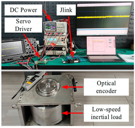
Figure 18.
The experimental set of low-speed measurement.
It is noteworthy that the proposed hardware structure employs high-accuracy sensors, which may raise concerns regarding cost and reliability in certain practical applications such as electric vehicle (EV) drives. While the current experimental setup focuses on validating the algorithm’s performance under laboratory conditions and does not include a dedicated stress test for sensor robustness, the simulation results in Section 4 have already evaluated the method’s performance under different encoder resolutions (equivalent to varying sensor accuracies). The results demonstrate that the improved ESO maintains satisfactory performance even with lower-resolution encoders (e.g., 16-bit), indicating its potential tolerance to sensor precision variations. Future work will involve implementing the algorithm on a more cost-effective hardware platform and conducting rigorous environmental stress tests to further validate its robustness for industrial and automotive applications.
Based on the aforementioned experimental setup, the performance of the four speed measurement methods was evaluated under step reference speeds. The steady-state speed fluctuations and transient response times were compared to quantitatively assess the effectiveness of the proposed improved ESO method.
Firstly, the reference speed was set to 10°/s. A comparison of the steady-state speed fluctuations and dynamic performance of the four methods is shown in Figure 19.
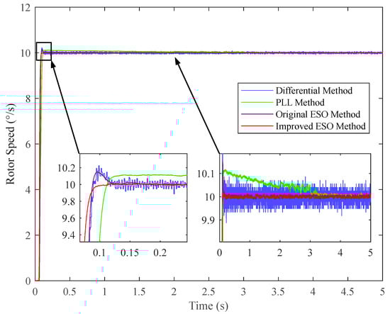
Figure 19.
Experimental results of the step response at 10°/s for different methods.
As shown in Figure 19, under a step response from 0°/s to 10°/s, the speed fluctuations of the two ESO-based methods are significantly lower than those of the other two methods. Furthermore, the improved ESO method exhibits better dynamic performance than the original ESO method. Specifically, the improved ESO method shows no overshoot during the step response, which can be attributed to the incorporation of the disturbance feedback loop that enhances system damping and robustness.
To further validate the method’s performance across different operating conditions, the reference speed was reduced to 6°/s. The corresponding experimental results are presented in Figure 20.
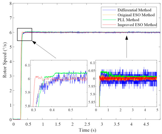
Figure 20.
Experimental results of the step response at 6°/s for different methods.
The results at 6°/s, as depicted in Figure 20, reinforce the trends observed at 10°/s. The improved ESO method consistently maintains the smallest speed fluctuation and the smoothest steady-state performance. It is noteworthy that as the speed decreases, the detrimental effects of quantization noise become more pronounced for all methods. However, the improved ESO method demonstrates superior noise suppression capabilities, thanks to its inherent filtering characteristics and the effective rejection of disturbances through the feedback mechanism. The PLL method shows increased fluctuation at lower speeds, while the differential method remains the most susceptible to encoder quantization noise, exhibiting the largest fluctuation.
Finally, to evaluate the performance of the proposed method under even more demanding low-speed conditions, the reference speed was further reduced to 2°/s. The corresponding experimental results are illustrated in Figure 21. At this extremely low speed, the adverse effects of encoder quantization and system disturbances become more pronounced.
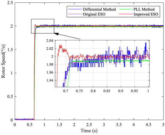
Figure 21.
Experimental results of the step response at 2°/s for different methods.
At this extremely low speed, the improved ESO method exhibits a slight overshoot during the transient phase, which can be attributed to the fixed control bandwidth not being adaptively adjusted as the reference speed decreases. The transient time of the phase-locked loop is approximately 0.076 s, followed by the differential and ESO methods with similar performance.
As shown in Figure 22, the steady-state performance differs among methods: the PLL exhibits a steady-state error of approximately 0.014°/s and fails to settle within the 5 s period, while the differential filtering method shows considerable speed fluctuations, and the two ESO methods demonstrate similar performance. Nevertheless, the improved ESO method still maintains outstanding steady-state fluctuation performance among all the methods, coupled with excellent transient performance, which collectively demonstrate its inherent noise suppression and disturbance rejection capabilities and validate its suitability for ultra-low-speed high-precision applications.
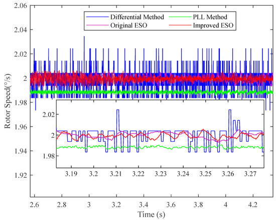
Figure 22.
Step response of different methods at 2°/s in stable state.
The quantitative performance metrics for the step response are summarized in Table 4. The maximum speed fluctuation in a steady state and the transient response time were measured for each method under 10°/s, 6°/s and 2°/s operating conditions.
Table 4.
Experimental Results of Transient Time and Steady-State Fluctuation for Different Speed Measurement Methods.
By compiling the data from Table 4, the line chart Figure 23 is obtained, which compares the experiment results of various speed measurement methods for PMSMs under low-speed conditions.
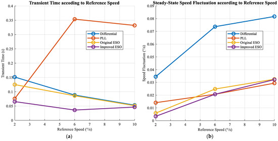
Figure 23.
Experimental Comparison of Transient and Steady-State Performance with Different Methods: (a) Transient time according to reference speeds; (b) Steady-state speed fluctuation according to reference speeds.
As evidenced by the experimental results summarized in Table 4 and illustrated in Figure 23, the proposed improved ESO method consistently outperforms conventional approaches across all tested operating conditions. In terms of dynamic response, the improved ESO achieves the shortest transient time at each reference speed. At 10°/s, it registers a transient time of 0.0465 s, which is marginally faster than the original ESO (0.0514 s) and significantly superior to the PLL method (0.3320 s). The most notable improvement is observed at 6°/s, where the transient time of 0.0361 s represents a reduction of 59.2% compared to the differential method (0.0885 s) and 89.8% compared to the PLL method (0.3539 s). Even at the challenging ultra-low speed of 2°/s, the improved ESO maintains a competitive transient time of 0.0656 s, outperforming both the differential (0.1514 s) and original ESO (0.1251 s) methods. In steady-state performance, the improved ESO delivers the lowest or comparable speed fluctuation across all test scenarios. It matches the PLL at 6°/s with a fluctuation of 0.0207°/s and shows a 60.6% improvement over the differential method. Most impressively, at 2°/s, it achieves the smallest fluctuation of 0.0034°/s, corresponding to a 42.4% improvement over the original ESO and a 90.1% improvement over the differential method. Although the performance gain over the original ESO in a steady state is modest at medium speeds, the consistent and substantial enhancement in transient performance—coupled with exceptional ultra-low-speed accuracy—validates the efficacy of the added disturbance feedback loop in bolstering both dynamic response and robustness under demanding operating conditions.
6. Application Prospects
The proposed improved third-order ESO demonstrates considerable potential for deployment in high-precision, low-speed servo systems, particularly within the context of electric vehicles (EVs). Its combination of high accuracy, computational efficiency, and robustness to disturbances makes it well-suited for cost-sensitive yet performance-critical automotive platforms.
A key application lies in Electric Power Steering (EPS) systems, where precision position output (error within ±0.5°) and rapid disturbance rejection are essential for driver comfort and safety [7]. The positional control accuracy of a permanent magnet synchronous motor (PMSM) is highly contingent upon the performance of its inner-speed loop. Consequently, the proposed method’s ability to significantly suppress speed fluctuations—by over 90% compared to conventional differentiation-based approaches—directly translates to smoother steering feel and improved performance during low-speed maneuvers such as parking or traffic jam assist. Furthermore, the method’s relatively low computational burden, achieved through straightforward algebraic operations in the feedforward and feedback paths, facilitates its integration into standard automotive-grade microcontrollers without demanding extensive additional resources.
As evidenced in Table 5, the proposed improved ESO achieves a superior balance between high steady-state accuracy and dynamic response. While the PLL method exhibits lower computational cost, its sluggish transient performance is less desirable for applications requiring quick corrections, such as sudden steering adjustments. The standard ESO, though competent, is outperformed by the improved ESO in both transient and steady-state performance, thanks to the integrated disturbance feedback. The primary advantage of the proposed method lies in its exceptional disturbance rejection capability without incurring a prohibitive computational overhead, rendering it a compelling solution for automotive systems like EPS where performance and cost must be carefully balanced. A noted consideration, as mentioned in Section “Experimental Setup for Low-Speed Motor Encoder Evaluation”, is the current reliance on high-accuracy sensors in our experimental validation. Future work will focus on implementing the algorithm on more cost-optimized hardware to further enhance its practicality for mass production.
Table 5.
Comparative analysis of speed measurement methods for EV low-speed applications.
Beyond in-vehicle systems, the technique also holds promise for infrastructure-level technologies that support intelligent transportation. For instance, the high-precision capabilities of the improved ESO could benefit the gimbal control of Control Moment Gyroscopes (CMGs), which are critical for satellite attitude stabilization. By improving the performance of CMGs, the method indirectly contributes to the accuracy and reliability of satellite-based navigation systems, which are foundational for autonomous driving platforms.
In summary, the improved ESO presents a practical and efficient solution for suppressing noise and disturbances in automotive servo systems. It not only enhances in-vehicle applications like EPS but also supports the broader intelligent transportation ecosystem through enabling higher performance in auxiliary technologies such as navigation-grade CMGs.
7. Conclusions
This study has developed and validated an improved third-order extended state observer for high-precision speed measurement in PMSM drives under low-speed conditions. Simulation and experimental results confirm that the proposed method significantly reduces steady-state speed fluctuation and improves dynamic response compared to conventional differentiation-based, phase-locked loop, and standard ESO approaches.
The key innovation lies in the incorporation of reference torque feedforward and active disturbance feedback, which enhances the decoupling between disturbance estimation and the current loop. This structure not only improves robustness against encoder quantization effects and external load variations but also maintains low computational complexity. The method achieves a reduction in steady-state speed fluctuation by up to 42% compared to the standard ESO and over 90.1% relative to differentiation-based methods, demonstrating its superior performance in both transient and steady-state operation.
Given these advantages, the improved third-order ESO is highly recommended for low-speed servo applications that demand high accuracy and strong disturbance rejection. It is particularly suitable for automotive systems such as electric power steering and automated parking, as well as other precision-critical domains including aerospace actuation and industrial servos. The significant noise suppression and enhanced robustness achieved by the proposed method directly address the critical requirements for smooth torque output and superior driver feel in EV applications such as Electric Power Steering (EPS), thereby validating its practical value for the next generation of intelligent vehicles.
Author Contributions
Methodology, R.J. and K.L.; Software, R.J., Y.W. and R.M.S.; Validation, R.J. and Y.W.; Formal analysis, R.J. and K.L.; Investigation, R.J.; Resources, K.L.; Data curation, R.J.; Writing—original draft, R.J.; Writing—review & editing, R.J., K.L. and R.M.S.; Visualization, R.J., Y.W. and R.M.S.; Supervision, K.L.; Project administration, K.L.; Funding acquisition, K.L. All authors have read and agreed to the published version of the manuscript.
Funding
This research was funded by Tianjin Navigation Instruments Research Institute, grant number 62602010313 and Aero Science Foundation of China, grant number 20240007069003.
Data Availability Statement
Data are contained within the article.
Conflicts of Interest
The authors declare no conflict of interest.
Abbreviations
The following abbreviations are used in this manuscript:
| PLL | phase-locked loop |
| ESO | extended state observer |
| KF | Kalman filter |
| EKF | extended Kalman filter |
| PMSM | permanent magnetic synchronous motor |
| LPF | low-pass filter |
| MCU | micro control unit |
| Res | resolution |
| Id, Iq | dq-frame current |
| Ia, Ib, Ic | abc-frame currents |
| θe | angle error between reference and feedback |
| pn | pole pair |
| Uα, Uβ | αβ-frame voltage |
| nc | critical speed |
| Kt | torque constant |
| J | load inertia |
| B | viscous friction |
| Te | electrical torque |
| Tl | load torque |
References
- Pellegrino, G.; Vagati, A.; Guglielmi, P.; Boazzo, B. Performance comparison between surface-mounted and interior PM motor drives for electric vehicle application. IEEE Trans. Ind. Electron. 2012, 59, 803–811. [Google Scholar] [CrossRef]
- Wang, G.; Fang, S. The Precision Improvement of Robot Integrated Joint Module Based on a New ADRC Algorithm. Machines 2024, 12, 712. [Google Scholar] [CrossRef]
- Wu, Z.; Yao, M.; Ma, H.; Jia, W. Improving Accuracy of the Vehicle Attitude Estimation for Low-Cost INS/GPS Integration Aided by the GPS-Measured Course Angle. IEEE Trans. Intell. Transp. Syst. 2013, 14, 553–564. [Google Scholar] [CrossRef]
- Sudhakar, M.; Vivekanand, K. Enhanced CNN based approach for IoT edge enabled smart car driving system for improving real time control and navigation. Sci. Rep. 2025, 15, 33932. [Google Scholar] [CrossRef]
- Li, H.; Chen, X.; Liu, G.; Cui, X. A Disturbance Estimation Approach to Self-Calibration of Gimbal Resolver-to-Digital Conversion System. IEEE Trans. Ind. Electron. 2023, 70, 793–802. [Google Scholar] [CrossRef]
- Zhang, Y.; Zhang, J. Disturbance characteristics analysis of CMG due to imbalances and installation errors. IEEE Trans. Aerosp. Electron. Syst. 2014, 50, 1017–1026. [Google Scholar] [CrossRef]
- Du, H.; Wang, L.; Chen, J.; Huang, H.; Feng, X. Integral Sliding-Mode Tracking Control for Heavy Vehicle Electrohydraulic Power Steering System. IEEE/ASME Trans. Mechatron. 2021, 26, 1455–1466. [Google Scholar] [CrossRef]
- Yang, C.; Fan, Y.; Zhang, Q. Speed Estimation from a Low-Resolution Encoder Using Adaptative Extend Kalman Observer in Low-Speed Range. In Proceedings of the 2021 IEEE 2nd China International Youth Conference on Electrical Engineering (CIYCEE), Chengdu, China, 15–17 December 2021; pp. 1–7. [Google Scholar]
- Wang, S.; Zhang, H.; Bao, Y.; Varvolik, V.; Prystupa, D.; Buticchi, G.; Li, J.; Zhang, X. A High Precision Resolver-to-Digital Conversion Method with Pre-filtering DDSRF Used in Electric Vehicle. In Proceedings of the 2022 IEEE Transportation Electrification Conference and Expo, Asia-Pacific (ITEC Asia-Pacific), Haining, China, 28–31 October 2022; pp. 1–6. [Google Scholar]
- Yin, X.; Guo, Y.; Na, J.; Fan, J. Incremental Optical Encoder Error Modeling and Compensation for Accurate Speed Acquisition in Non-Stationary Conditions. IEEE Trans. Ind. Electron. 2025, 72, 1033–1042. [Google Scholar] [CrossRef]
- Dalboni, M.; Soldati, A. Absolute Two-Tracked Optical Rotary Encoders Based on Vernier Method. IEEE Trans. Instrum. Meas. 2023, 72, 9501412. [Google Scholar] [CrossRef]
- Benevieri, A.; Marchesoni, M.; Passalacqua, M.; Vaccaro, L. Experimental Low-Speed Performance Evaluation and Comparison of Sensorless Passive Algorithms for SPMSM. IEEE Trans. Energy Convers. 2022, 37, 654–664. [Google Scholar] [CrossRef]
- Qu, J.; Zhang, P.; Jatskevich, J.; Zhang, C. Torque-Ripple Reduction of Permanent Magnet Synchronous Machine Drives Based on Novel Speed Harmonic Control at Low-Speed Operation. IEEE Trans. Ind. Electron. 2023, 70, 7683–7694. [Google Scholar] [CrossRef]
- Bai, Y.; Tang, X.; Chen, J.; Peng, F. Research on Ultra-low speed control of PMSM in servo system. In Proceedings of the 2008 7th World Congress on Intelligent Control and Automation, Chongqing, China, 25–27 June 2008; pp. 2381–2386. [Google Scholar]
- Yan, Y.; Zhang, X.; Xia, C.; Ji, B.; Wang, Z. Speed measurement algorithm for low-speed permanent magnet synchronous motor based on overlapped measurement regions. In Proceedings of the 25th International Symposium on Industrial Electronics (ISIE), Santa Clara, CA, USA, 8–10 June 2016; pp. 204–209. [Google Scholar]
- He, C. The digital filter method designing of angular rate of the servo control system in low speed. In Proceedings of the International Conference on Electronic & Mechanical Engineering and Information Technology, Harbin, China, 12–14 August 2011; pp. 4890–4893. [Google Scholar]
- Wang, Y.; Zhang, H.; Liu, K.; Hu, M.; Wu, Z.; Zhang, C.; Hua, W. A Forward Compensation Method to Eliminate DC Phase Error in SRF-PLL. IEEE Trans. Power Electron. 2022, 37, 6280–6284. [Google Scholar] [CrossRef]
- Yuan, X.; Chen, J.; Liu, W.; Lee, C.H.T. A Linear Control Approach to Design Digital Speed Control System for PMSMs. IEEE Trans. Power Electron. 2022, 37, 8596–8610. [Google Scholar] [CrossRef]
- Wang, C.; Wu, W.; Li, G.; Yang, G.; Zhang, C.; Pan, J. Design of Full-Order State Observer for Motor Drive Systems Based on the Fixed Gain Filter. IEEE Access 2021, 9, 13488–13498. [Google Scholar] [CrossRef]
- Shi, T.; Wang, Z.; Xia, C. Speed Measurement Error Suppression for PMSM Control System Using Self-Adaption Kalman Observer. IEEE Trans. Ind. Electron. 2015, 62, 2753–2763. [Google Scholar] [CrossRef]
- Thielemans, Y.; Kayedpour, N.; Coene, A.; Crevecoeur, G.; De Kooning, J.D.M. Speed and Position Measurement of Rotating Machinery with a Triangular Pattern Vision Encoder. IEEE Trans. Instrum. Meas. 2025, 74, 5029913. [Google Scholar] [CrossRef]
- Hou, Q.; Xu, S.; Zuo, Y.; Wang, H.; Sun, J.; Lee, C.H.T.; Ding, S. Enhanced Active Disturbance Rejection Control with Measurement Noise Suppression for PMSM Drives via Augmented Nonlinear Extended State Observer. IEEE Trans. Energy Convers. 2024, 39, 287–299. [Google Scholar] [CrossRef]
- Li, T.; Zhao, Y.; Hou, L. Adaptive Sliding Mode Control with Disturbance Observer for Speed Regulation System of Permanent Magnet Synchronous Motor. IEEE Access 2023, 11, 17021–17030. [Google Scholar] [CrossRef]
- Hamida, M.A.; Leon, J.D.; Glumineau, A.; Boisliveau, R. An adaptive interconnected observer for sensorless control of PM synchronous motors with online parameter identification. IEEE Trans. Ind. Electron. 2013, 60, 739–748. [Google Scholar] [CrossRef]
- Wang, W.; Ye, Y.; Chen, X.; Yuan, Y. Adaptive High-Order Sliding-Mode Low-speed Control with RBF Neural Network Nonlinear Disturbance Observer for PMSM Drive System. IEEE Trans. Power Electron. 2025, 40, 10865–10876. [Google Scholar] [CrossRef]
- Li, H.; Yang, S.; Le, Y. Torque Ripple Minimization of Low-Speed Gimbal Servo System Using Parameter-Optimized ESO. IEEE J. Emerg. Sel. Topics Power Electron. 2023, 11, 2094–2103. [Google Scholar] [CrossRef]
- Wang, Y.; Yu, H.; Che, Z.; Wang, Y.; Zeng, C. Extended State Observer-Based Predictive Speed Control for Permanent Magnet Linear Synchronous Motor. Processes 2019, 7, 618. [Google Scholar] [CrossRef]
- Zhu, S.; Huang, W.; Zhao, Y.; Lin, X.; Dong, D.; Jiang, W.; Zhao, Y.; Wu, X. Robust Speed Control of Electrical Drives with Reduced Ripple Using Adaptive Switching High-Order Extended State Observer. IEEE Trans. Power Electron. 2022, 37, 2009–2020. [Google Scholar] [CrossRef]


Disclaimer/Publisher’s Note: The statements, opinions and data contained in all publications are solely those of the individual author(s) and contributor(s) and not of MDPI and/or the editor(s). MDPI and/or the editor(s) disclaim responsibility for any injury to people or property resulting from any ideas, methods, instructions or products referred to in the content. |
© 2025 by the authors. Published by MDPI on behalf of the World Electric Vehicle Association. Licensee MDPI, Basel, Switzerland. This article is an open access article distributed under the terms and conditions of the Creative Commons Attribution (CC BY) license (https://creativecommons.org/licenses/by/4.0/).