1. Introduction
Against the backdrop of worsening global climate change and environmental pollution, issues such as the greenhouse effect and ozone layer depletion caused by the energy crisis have attracted significant attention from the international community. Vehicle exhaust emissions are one of the core sources of urban environmental pollution, with harmful impacts spanning areas including human health, the ecological environment, and climate change. Therefore, developing new energy vehicles is not only a necessary measure to control pollution, reduce carbon emissions, and ensure energy security, but also a key driver for industrial upgrading. It holds great significance and urgency for ecological sustainability, economic competitiveness, and the long-term development of the country. As one of the core components of electric vehicles, the power battery pack provides the energy source for electric vehicles. During vehicle operation, the battery pack is subjected to various acceleration impacts and cyclic loads under complex, extreme working conditions. These loads may cause two key issues: (1) insufficient strength and stiffness of the battery pack; (2) fatigue failure risks in the case and lifting lug structures. Its safety performance has become a focal point in the development of new energy vehicles and a core concern of consumers [
1]; only by fully ensuring safety can pure electric vehicles gain market trust and expand their development space.
In the structural research of power battery systems, modal analysis, inertial force analysis, and random vibration test verification conducted on a specific power battery system revealed a box cracking phenomenon at the lifting lug positions. After the research team optimized the local structure of the battery box by combining simulation and test results, both its safety and reliability met the design requirements [
2]. Xu et al. [
3] conducted safety performance analysis on the power battery pack of a certain logistics vehicle under drop and extrusion working conditions. They optimized the parts that failed to meet the requirements, which verified the accuracy of the dynamic analysis and structural optimization methods for the battery pack. The team led by Akhoundzadeh, M.H. Reference [
4] focused on the impact of battery pack structural layout on packaging efficiency. They established a refined finite element model to simulate the spatial distribution of battery cells under different arrangement modes, thereby improving the energy density of the battery pack. In terms of static and dynamic operating condition analysis, some studies have used finite element simulation to analyze the static performance of a certain battery pack under three extreme operating conditions: bumpy hard braking, bumpy sharp turning, and torsion. These studies found that the structural strength and stiffness were over-designed. Subsequently, local topology optimization (material reduction of internal reinforcing ribs) and Isight-based global size optimization were carried out. Ultimately, a 12.3% weight reduction of the battery pack structure was achieved, while the cruising range was increased by 11.1% [
5,
6]. Garg et al. [
7,
8,
9] analyzed the reliability and safety of the battery case through finite element modeling. Based on the results of the strength analysis, they carried out an improved design of the battery pack structure, which provided a theoretical basis for the finalization design of the battery pack product structure. Suhas S K et al. [
10] evaluated the mechanical integrity of lithium-ion batteries through finite element simulation, and proposed and analyzed four modeling methods, namely heterogeneous, homogeneous, hybrid, and sandwich methods. They simulated the spherical indentation test of pouch batteries to investigate the capability and applicability of each method, studied the effects of separator parameters and anisotropy on the stress and failure points of the batteries, and finally discussed the advantages and disadvantages of the methods. They suggested using partial element modeling for simplification to reduce the simulation time and complexity. Yongjun P et al. [
11] proposed a lightweight design for the outer shell of an electric vehicle battery case under loading conditions, based on advanced high-strength steel (AHSS) and dimension optimization. They determined the material selection and thickness of the shell through constant-frequency vibration analysis and further analyzed the relevant numerical results using mechanical impact analysis and fatigue life analysis. German scholars such as Uerlich R [
12] conducted research on battery pack packaging design. Referring to the crashworthiness of electric vehicle components, they carried out extrusion simulation analysis on battery module models with three different arrangement forms. By studying the stress curves and values in the simulation results, they found that the hexagonal arrangement structure exhibited obvious advantages in the mechanical properties of the battery pack. Arslan M et al. [
13,
14] took the development of a new energy vehicle battery pack system as a case study. They adopted advanced Glass Fiber Reinforced Polymer (GFRP) materials and an innovative hybrid structure design and established a finite element model that aligns with actual working conditions. The aim was to enhance the crashworthiness and lightweight performance of the battery pack, thereby providing simulation data support for the safety design and optimization of the battery pack.
Most previous studies have focused on single or a few independent operating conditions, resulting in the lack of working condition coupling. Moreover, most studies only simulated independent operating conditions and failed to consider the scenario where “vibration-torsion-impact” multiple operating conditions act simultaneously during actual vehicle operation, which leads to a discrepancy between safety assessment and real-service environments. In actual vehicle operation, battery packs often withstand the coupled effects of multiple working conditions such as vibration, torsion, and extrusion. The analysis results under a single working condition may not be applicable to complex scenarios, which can cause insufficient safety redundancy or performance waste during real service. Based on the above limitations of existing studies, this paper, from the perspective of structural analysis and taking linear and nonlinear simulations as the research direction, constructs a multi-dimensional coupling evaluation system. It conducts stiffness, strength, and safety simulations on a power battery pack model, forming a full-scenario safety verification process covering “vibration-torsion-impact”. This not only compensates for the limitations of single-working-condition evaluation and fully explores the rationality of the model’s structural design but also provides guidance for subsequent improvements and actual production work. The technical route is shown in
Figure 1.
2. Establishment of the Finite Element Model of the Power Battery Pack
Computer-Aided Engineering, commonly known as CAE (Computer-Aided Engineering), involves analyzing the physical performance of products and optimizing them through computer analysis of complex engineering problems. In the automotive industry, CAE technology has been widely applied throughout the entire process of vehicle research and development, production, testing, and improvement. Battery packs are expensive, and using computer-aided engineering for analysis and optimization can reduce Research and development costs.
In this study, three finite element analysis software packages—HyperMesh, Optistruct, and LS-DYNA—were mainly adopted based on the requirements of different analysis tasks. Among them, HyperMesh was used for structural modeling and meshing of the battery pack, with its advantage lying in high compatibility with complex geometric models, which enables accurate reproduction of the assembly relationship between the internal modules and brackets of the battery pack. Optistruct and LS-DYNA were applied for subsequent mechanical performance simulation; specifically, LS-DYNA has greater advantages in the calculation accuracy of material nonlinear behavior and can more realistically simulate the stress distribution of the battery pack under extreme working conditions.
2.1. Battery Pack Structure Design
In this paper, a physical model is established for the prototype of a lithium-ion battery pack developed by the research group for small urban pure electric vehicles. The overall structure mainly consists of the lower shell, upper cover, BMS, battery modules, high and low voltage cable connectors, heating system, and mechanical fastening devices, among other components. The dimensions of the power battery pack are length 1060 mm, width 710 mm, height 130 mm, with a total weight of approximately 112 kg.
Figure 2 shows the three-dimensional model of the battery pack established in Catia.
2.2. Geometric Processing of Power Battery Packs
After importing the 3D model of the battery pack built in Catia into HyperMesh, geometric simplification is required due to the model’s structural complexity. The simplification is carried out in two main aspects: On one hand, components that do not bear loads are removed, and non-load-bearing parts are simplified. These include non-core analysis objects such as BMS slave acquisition modules, heating sheets inside the battery pack, and insulation baffles. Meanwhile, electronic components that have little impact on simulation results or are lightweight—such as wire harnesses, relays, and sensors—are deleted; their effects will be addressed through weight balancing in subsequent steps [
15]. On the other hand, minor detailed features—such as the rounded chamfers of brackets and non-load-bearing small holes on the case—are omitted. This prevents such features from disrupting mesh regularity and compromising simulation accuracy. A battery cell consists of multiple layers, including the positive electrode, negative electrode, electrolyte, separator, and outer casing. If fine meshing were performed for each layer, the complexity of the finite element model would increase significantly, which in turn would greatly reduce the efficiency of subsequent simulation calculations. Schröder T and other scholars [
16] conducted real-time simulations of power tool battery packs on a mechatronic powertrain test bench. They simultaneously parameterized the model using three different programs and verified the simulated model by comparing it with the actual operating behavior of the battery. Ultimately, this study successfully achieved a well-balanced combination of practicality and reliability between the accuracy of the battery model and the ease of operation when testing the electromechanical system, providing a feasible solution for the efficient application of battery models. In view of this, to balance model accuracy and computational efficiency, this study models the battery module as an equivalent homogenized structure. After completing the aforementioned simplification, operations such as geometric cleaning, mesh generation, connection establishment, and material property assignment are carried out in sequence. Moreover, mesh quality is strictly controlled during the mesh generation process, as shown in
Table 1.
After repeated inspection and optimization adjustments, the finite element model elements of the battery pack structure meet the requirements of the aforementioned standards. Among them, the number of triangular elements accounts for 0.4% of the total number of elements, which is far less than 5%. To ensure the accuracy of simulation results and mesh independence, a mesh convergence study was conducted before the formal analysis. The low-order natural frequency of the battery pack was selected as the convergence criterion, as it is a fundamental global response sensitive to the overall mesh density. Three gradually refined mesh schemes (with approximately 200,000, 400,000, and 600,000 nodes) were generated. The results show that when the mesh is refined from the medium scheme (the scheme adopted in this study, with 393,320 nodes) to the finest scheme, the change in the first-order natural frequency is less than 1.5%. This proves that the selected mesh density can provide convergent results for subsequent linear and nonlinear simulations, achieving a reliable balance between calculation accuracy and efficiency. Therefore, a gradient mesh scheme design was finally determined, with a global mesh size of 8 mm and a size of 5 mm for locally refined areas such as lifting lugs [
17,
18]. The final model has a total of 393,320 nodes and 367,357 elements. The finite element models of the homogenized battery module and the entire battery pack are shown in
Figure 3.
In the HyperMesh 2025 software, first, create corresponding Components for each part of the 3D model of the power battery pack and perform mesh division on each Component; then, reasonably connect the discretized parts and assign corresponding properties and material parameters to each Component, where the material property details of each part of the battery pack are shown in
Table 2. The material properties of the battery pack are shown in
Table 2.
3. Modal Analysis of Power Battery Pack
3.1. Basic Theory of Modal Analysis
When a vehicle is moving, it generates vibrations, and the battery pack vibrates accordingly. Modal analysis can effectively obtain the vibration frequency range of a structure; therefore, to prevent resonance caused by the proximity between various excitations generated during the operation of an electric vehicle and the natural frequency of the battery pack, it is necessary to verify the safety and reliability of the battery pack through modal analysis. The dynamic differential equation of a multi-degree-of-freedom linear Vibration system is shown in Equation (1).
In the equation, represents the mass matrix; represents the damping matrix; represents the stiffness matrix; represents acceleration; represents velocity; represents displacement; represents the external excitation load matrix.
Modal shapes and natural frequencies are inherent characteristics of the structure itself, mainly determined by factors such as the structure’s own shape and material properties, and are independent of external loads. Since the battery pack structure studied belongs to the free mode, damping and external loads are not considered in the modal analysis. After simplifying Equation (1), the undamped free vibration equation obtained is shown in Equation (2).
Since the displacement vector
in Equation (2) is a general expression for structural displacement, it needs to be further defined as a harmonic vibration displacement form in modal analysis. Let the displacement response of a certain node of the structure be
; the relationship between
and
in Equation (2) is
=
, which represents the time-varying functional form of the displacement vector. Therefore, the harmonic vibration displacement solution is substituted as follows:
In the equation,
denotes the amplitude column vector;
denotes the natural frequency. Substitute them into Equation (2), calculate the second-order time derivative of
to obtain
, and then simplify after substitution to get:
Since
is not identically zero, the eigenvalue equation can be derived as follows:
When a system undergoes free vibration, the amplitude of each node in the system is not all zero, meaning it is non-zero. Therefore, the frequency equation for the system’s free vibration is
In the above expression, is n-order stiffness matrices and is n-order mass matrices. By solving the linear algebra system of equations, the n eigenvalues (i = 1, 2, 3, …, n) can be obtained, where is the i-th natural frequency of the system. Substituting the results into Equation (4) allows us to calculate the i-th mode shape vector (i = 1, 2, 3, …, n). After mass normalization, the inherent mode shapes representing the relative deformation of the structure can be obtained.
3.2. Modal Analysis and Evaluation of Power Battery Packs
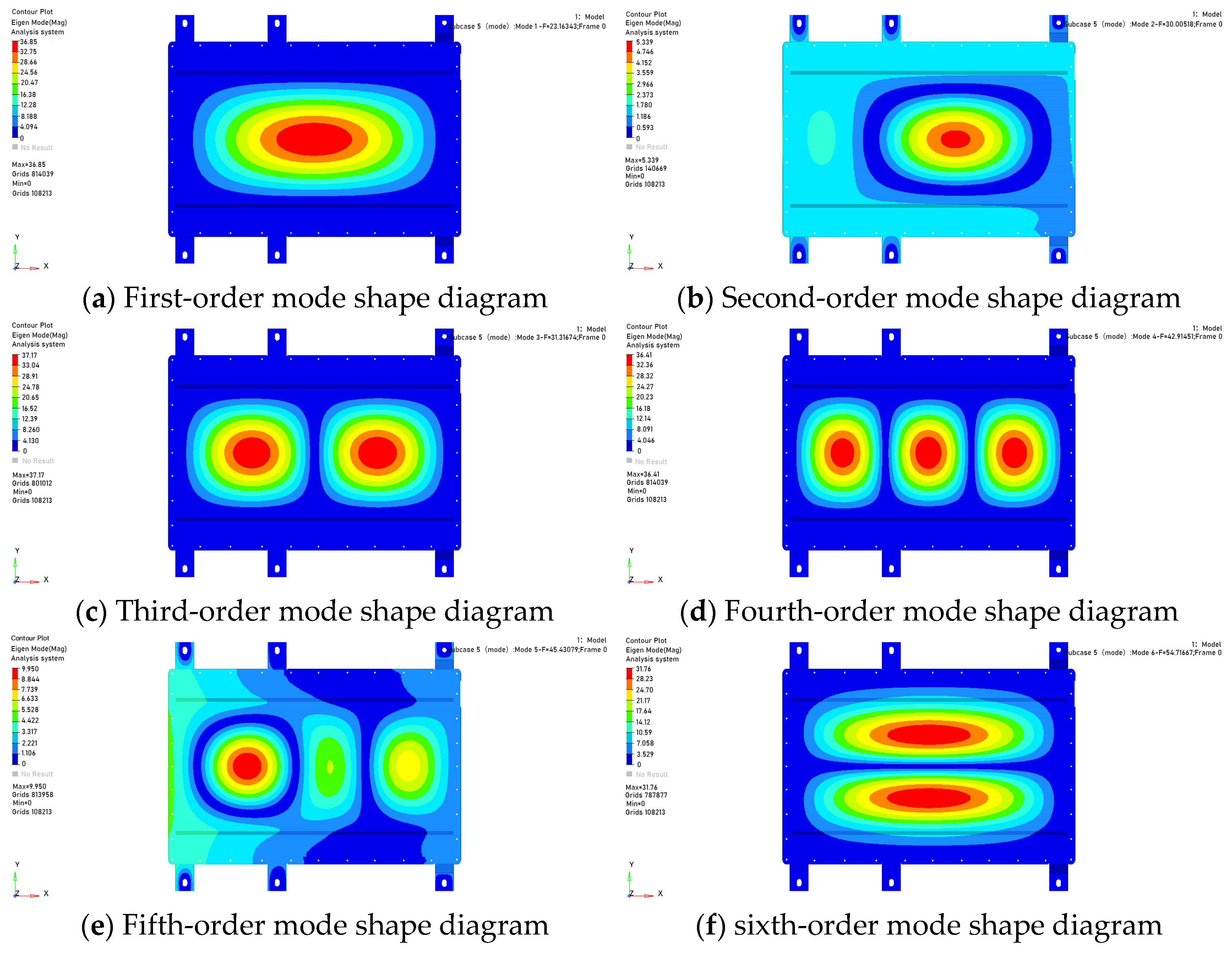
A finite element model established in HyperMesh software will be constrained in the middle of the fixed bracket bolt connection according to the assembly position with the car body, restricting its six degrees of freedom. After solving with Optistruct, the first six natural frequencies will be extracted. The natural frequency data is shown in
Figure 4.
The inherent frequencies and vibration modes of each stage are described in
Table 3.
During the operation of electric vehicles, the excitation effect produced by the drive motor and the excitation caused by uneven road surfaces are the main reasons for the resonance between the battery pack’s inherent frequencies and the vehicle’s frequencies.
- (1)
The excitation frequency of the motor is generally less than 25 Hz.
- (2)
The excitation caused by uneven road surfaces is related to road conditions and the speed of the electric vehicle. The equation for calculating the road surface vibration frequency is
In the equation,
is the maximum speed of the electric vehicle,
is the wavelength of the road unevenness, and
Table 4 shows the vibration wavelengths of different road types in China.
Since the electric vehicles studied in this article mainly operate on smooth urban roads, with the main driving area being the city and a maximum speed of 100 km/h, the wavelength of the road surface bumps is 1 [
19]. Substituting it into Equation (7) gives a road excitation frequency of 27.8 Hz.
In summary, the first natural frequency of the battery pack is 23.16 Hz, which is lower than the excitation frequency of the road surface at 27.8 Hz. This indicates that the excitation frequency caused by road unevenness is likely to resonate with the first natural frequency of the battery pack Combining with the natural frequency modal diagram, it can be seen that the excitation point is located in the middle of the upper cover, indicating insufficient stiffness at this location.
5. Simulation Analysis of Power Battery Pack Extrusion Safety
In safety accidents such as automobile collisions, power batteries may withstand extrusion impacts. Such extrusion can further cause compressive damage to components inside the battery, including internal circuits, controllers, and high-low voltage wiring harnesses, which in turn triggers safety risks such as short circuits and fires [
21,
22]. To evaluate the strength and stability of the battery pack under complex collision scenarios, the extrusion condition analysis of the battery pack can be carried out using a simplified model, so as to simulate the actual situation where electric vehicles are subjected to collisions from different directions. First, the extrusion model of the power battery pack is established through the LS-DYNA module in HyperMesh software, and then LS-DYNA software is used to calculate the k-file, thereby completing the extrusion simulation analysis of the power battery pack [
22].
According to the provisions of the safety test extrusion test [
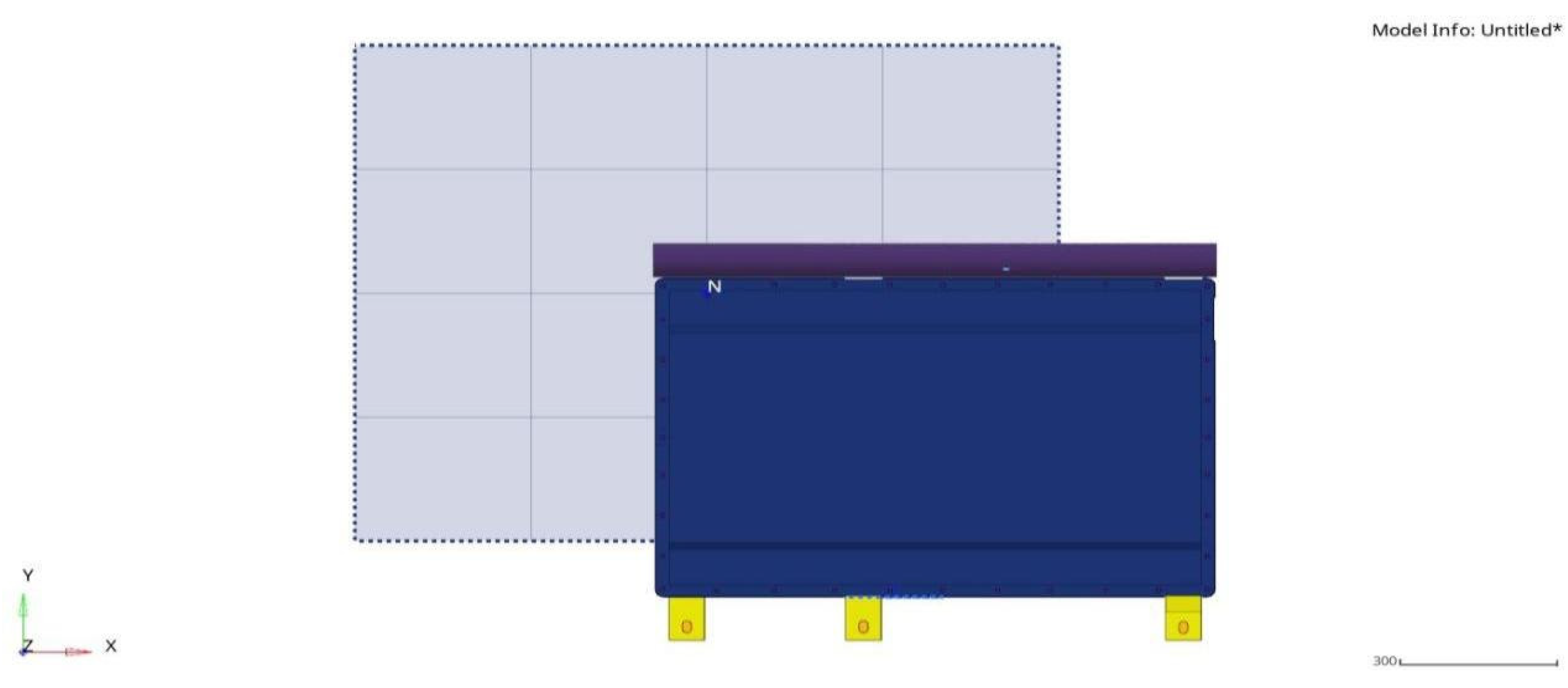
23], a semi-cylinder with a radius of 75 mm is used as the extrusion plate in the test, and the length of the extrusion plate must be greater than the height of the battery pack under test. The extrusion process shall be carried out along two directions (X and Y), which, respectively, represent the frontal impact that may occur when the vehicle is moving forward and the collision force from the side: the X direction corresponds to the vehicle’s running direction, while the Y direction is the horizontal direction perpendicular to the vehicle’s forward direction. The test termination conditions are the extrusion force reaches 100 kN, or the extrusion deformation reaches 30% of the overall dimension in the extrusion direction. After reaching either condition, this state shall be maintained for 10 min, followed by a 1 h observation period; during the entire process, the battery pack is required to have no phenomena such as ignition or explosion. The finite element model for extrusion in the X direction is shown in
Figure 7, and the finite element model for extrusion in the Y direction is shown in
Figure 8.
- (1)
Analysis of Extrusion Results in the X Direction
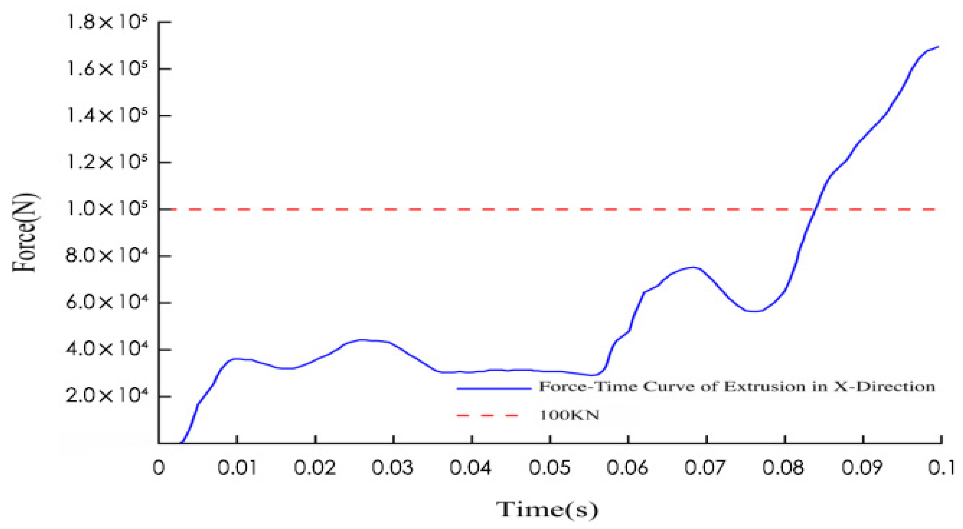
After the k-file was established and solved in HyperMesh, it was imported into the LS-DYNA solver for calculation. The force-time curve of the semi-cylinder under the X-direction extrusion condition obtained from the calculation is shown in
Figure 9. From 0 to 0.02 s, the extrusion force jumped to approximately 4 × 10
4 N in a short period. This phase corresponds to the initial contact stage between the extrusion plate and the battery pack, reflecting the mechanical impact at the moment of contact and the rapid transmission of stress, which is a direct response to the initiation of the extrusion action. From 0.02 s to 0.07 s, the extrusion force oscillated within the range of 2 × 10
4 to 7.5 × 10
4 N, with multiple small peaks and valleys appearing. During this period, friction occurred between the extrusion plate and the battery pack immediately after contact, and micro-deformations emerged inside the material, leading to repeated oscillations of the extrusion force. From 0.07 s to 0.1 s, the extrusion force started to rise continuously from 5.5 × 10
4 N, reached 1 × 10
5 N at 0.084 s, and approached 1.7 × 10
5 N until the end of the phase. At this stage, the material deformation entered a critical period, and the extrusion force increased sharply with the progress of extrusion, representing the high-intensity mechanical output in the final stage of extrusion.
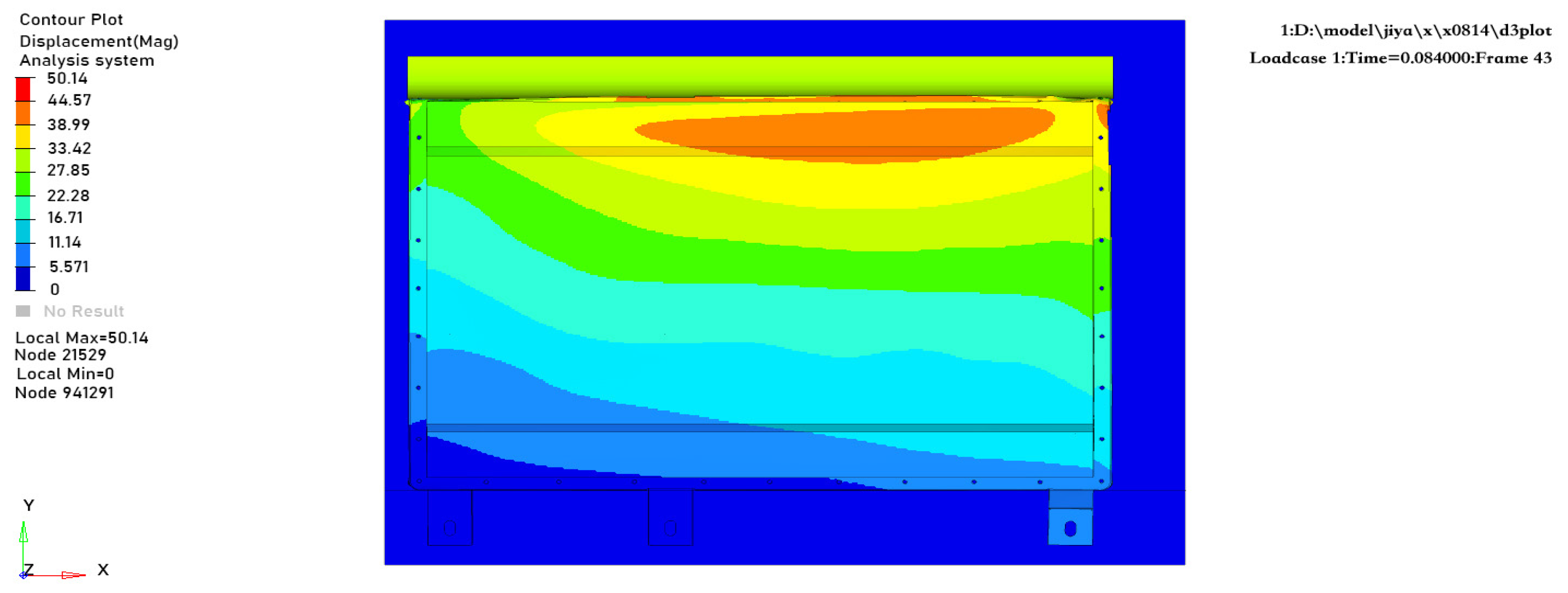
When the extrusion force reached 100 kN, the extrusion deformation of the battery pack is shown in
Figure 10. From the simulation results, it can be clearly observed that the deformation of the battery pack exhibits a significant characteristic of regional concentration: the deformation mainly occurs at the chamfered part of the top end of the battery pack’s upper cover, with a deformation amount of 50.14 mm. To evaluate the safety of the battery pack’s internal structure, the relative positional relationship between the battery module and the case was measured. The results show that the distance between the head of the battery module and the edge of the case is 90 mm; therefore, the case does not come into direct contact with the internal battery module, which effectively avoids safety risks caused by collisions between the module and the case, indicating excellent safety performance of the battery pack.
- (2)
Analysis of Extrusion Results in the Y Direction
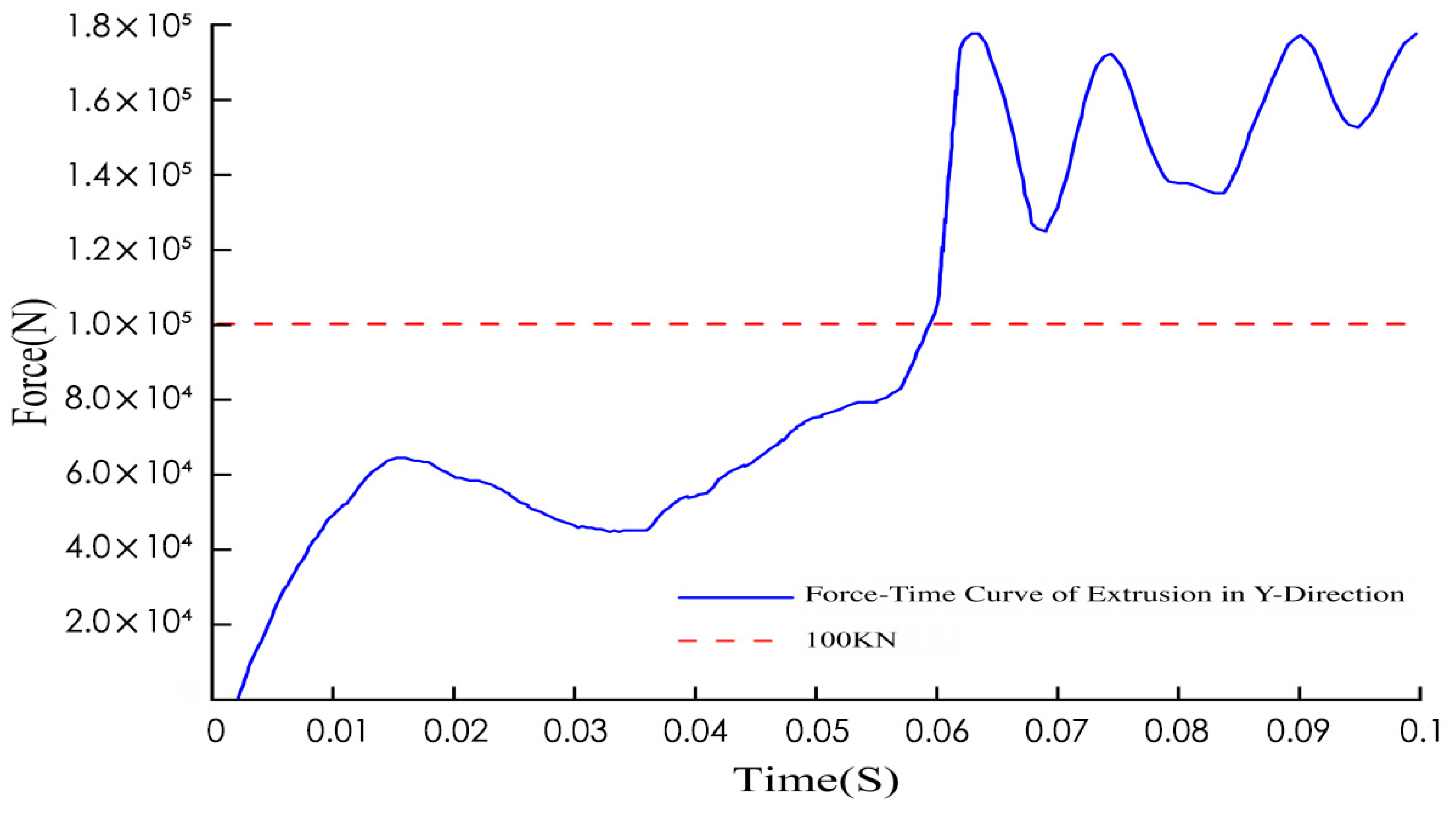
The force-time curve of the semi-cylinder under the Y-direction extrusion condition is shown in
Figure 11. From 0 to 0.015 s, the extrusion force sharply increases from 0 to approximately 6 × 10
4 N in a short period, forming the first obvious peak. This phase corresponds to the initiation of Y-direction extrusion: when the extrusion plate comes into contact with the edge of the battery pack, the extrusion force rises in an “explosive” manner within an extremely short time. This phenomenon reflects the mechanical impact at the moment of contact and represents a typical mechanical behavior during the extrusion initiation stage. From 0.015 to 0.055 s, the extrusion force decreases from the peak and fluctuates within the range of 4 × 10
4 to 8 × 10
4 N. During this period, the battery pack case and its internal structure generate mechanical feedback, causing small fluctuations in the extrusion force, which overall remains within a relatively stable medium-to-low intensity range. From 0.055 to 0.1 s, the extrusion force starts to rise sharply from 8 × 10
4 N; after exceeding the 1 × 10
5 N reference line at 0.058 s, it enters a high-frequency oscillation state. The peak value of the oscillation is close to 1.8 × 10
5 N, while the valley value remains above 1.2 × 10
5 N. Here, the high-frequency oscillation reflects the complex mechanical interactions of the model, which is related to factors such as changes in the internal structure of the material, and embodies the high-intensity, dynamic mechanical characteristics of the battery pack during the final stage of Y-direction extrusion.
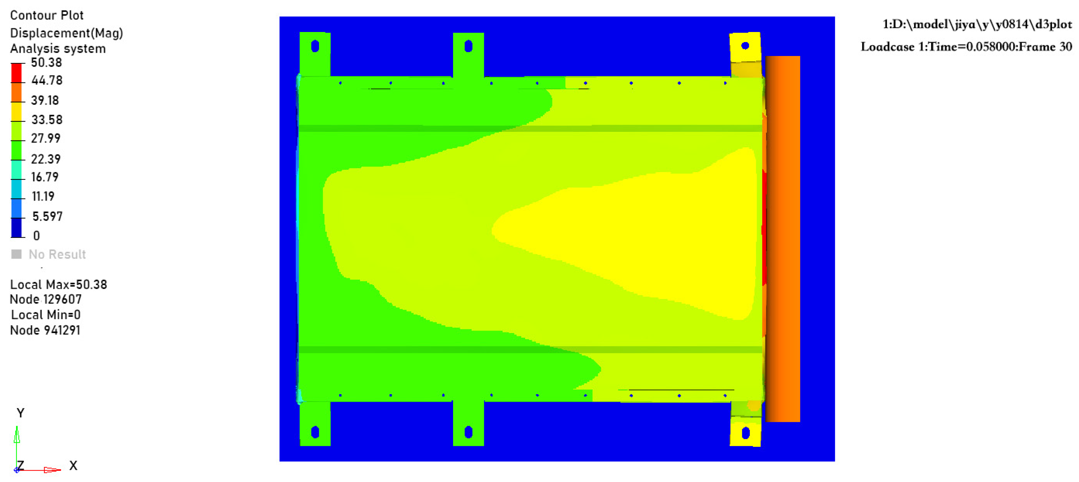
When the extrusion force reaches 100 kN, the extrusion deformation of the battery pack is shown in
Figure 12. The deformation of the battery pack is mainly concentrated at the contact area between the semi-cylindrical extrusion plate and the side wall of the lower case, with a deformation amount of 50.38 mm. Measurements indicate that the distance between the side of the battery module and the edge of the case is 99 mm; therefore, the case does not come into direct contact with the battery module, demonstrating good safety performance.
From the results of the extrusion condition analysis, benchmark verification was conducted with the technical requirements for battery pack extrusion performance specified in the national standard GB/T 38031-2025 as the core basis. When the extrusion force reaches 100 kN, there is no direct contact between the battery pack case and the internal modules, and the case has no severe damage (such as cracking) that may cause it to lose its service function, which fully meets the core requirements of this standard for battery pack extrusion safety performance.
6. Conclusions
Aiming at the limitation of the existing single-working-condition evaluation of battery packs, this study takes the battery pack of a certain urban small pure electric vehicle under development as the object. Through finite element simulation, the multi- working-condition evaluation of “dynamic stiffness-static strength-extrusion safety” is completed, and the conclusions are as follows:
- (1)
Response to research objectives
Through the analysis of three dimensions, namely modal, static, and extrusion, the safety performance of the battery pack under multi-working-condition scenarios of “vibration-static load-collision extrusion” is verified. By controlling mesh quality, accurately assigning material parameters, and strictly matching boundary conditions, the engineering reliability of the simulation results is ensured, providing a quantitative basis for structural optimization.
- (2)
Summary of Core Results
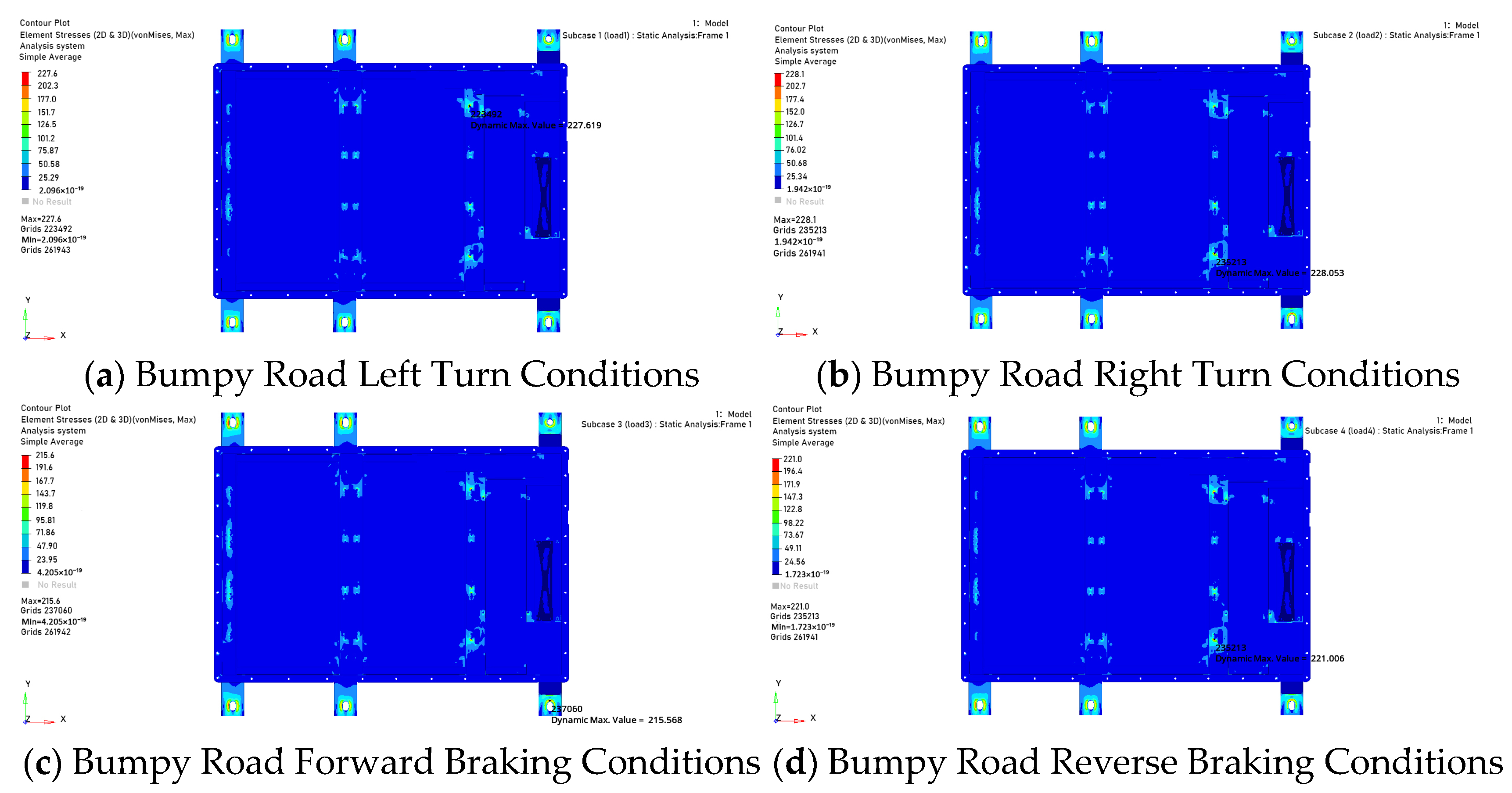
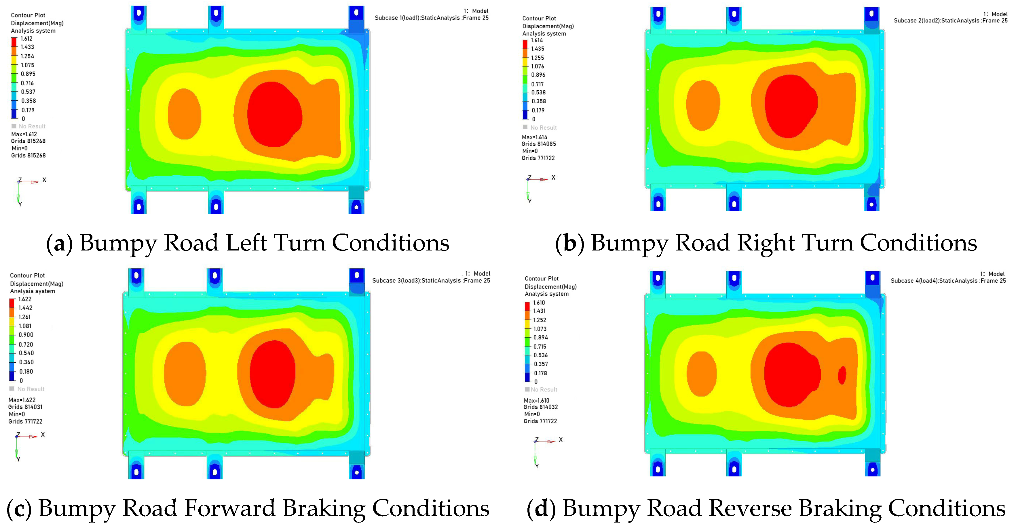
In the modal characteristic analysis, the vibration characteristics were solved using the finite element model of the battery pack. The first-order natural frequency was found to be 23.16 Hz, and the mode shape showed that the maximum amplitude was 36.85 mm, located in the middle of the upper cover. This indicates that the excitation frequency of road unevenness may resonate with the natural frequency of the battery pack, posing a potential risk of structural damage. To verify the structural reliability under static loads, simulations were conducted for 4 typical static working conditions. The results showed that the maximum stress was 228.1 MPa, which is less than the material yield limit; the maximum displacement was 1.622 mm, within the allowable deformation range. Additionally, the safety factors of key parts such as the lower case support structure and the top cover connection area were all greater than 1, indicating that the static strength meets the design and application requirements. The extrusion working condition simulation was carried out in accordance with GB/T 38031-2025, simulating lateral and forward extrusion scenarios. The results showed that the maximum deformation in the X-direction was 35.20 mm, and that in the Y-direction was 26.10 mm. Both values are less than the reserved safety distance between the internal modules and the edge of the case. No contact or extrusion between the modules and the case occurred, demonstrating that the battery pack can effectively protect the cells and its safety performance meets the collision safety standards.
- (3)
Research Significance
A “modal-static-extrusion” multi-operating-condition coupling analysis framework was established, which fills the gap of single-operating-condition evaluation in existing studies. This framework provides a reusable methodology for the safety performance simulation of battery packs, and its results can also guide engineering optimization.
- (4)
Future Research Prospects
In subsequent studies, simulations of composite environments such as “low temperature-vibration” and “impact-extrusion” can be incorporated to better align with the actual service scenarios under extreme climates. Additionally, physical tests can be used to calibrate simulation parameters, further improving the credibility of results and forming a “simulation-test” two-way verification system.


