Abstract
The finite element model (FEM) for induction motors (IM) was developed and validated through experimental testing. The validated FEM provides a reliable basis for further optimization of the electric machine. A strong sliding mode technique, in conjunction with field-oriented control (FOC), is proposed for speed control of the IM. The sliding mode controller ensures steady functioning in the face of ambiguities and disruptions, while FOC enables precise control of the motor’s magnetic field. This combination enhances both the efficiency and accuracy of speed control in IM, making it a valuable tool for industrial applications. The proposed sliding mode control (SMC) was fine-tuned using the advantages produced by the ant colony optimization algorithm. This approach aids in resolving issues and delivers optimal speed and field responses. Simulation and experimental results demonstrate the effectiveness of the proposed approach. The optimized induction motor achieved a 28% reduction in rotor Joule losses, resulting in improved energy efficiency. Additionally, using Ant Colony Optimization to adjust the SMC parameters led to a 99.74% reduction in speed tracking error and a 99.59% reduction in flux error compared to traditional manual tuning. These substantial improvements confirm the superiority of the proposed method for high-performance and energy-efficient electric vehicle applications.
1. Introduction
Electric vehicles (EVs), especially light electric vehicles (LEVs), are increasingly adopted as eco-friendly alternatives to traditional internal combustion engine (ICE) vehicles. This shift is driven by growing environmental concerns and the depletion of fossil fuels resources. LEVs are a good choice for eco-friendly transportation because they have many benefits, such as lower greenhouse gas emissions and higher energy efficiency [1,2]. Despite advances in electric vehicle technology, further improvements in powertrain efficiency and energy utilization remain essential for widespread adoption. Achieving broader adoption of LEVs requires continued enhancement of these aspects. The battery acts as the principal energy source, and the powertrain regulates the efficiency of energy conversion to mechanical output. Battery technology plays a critical role in determining the performance and service life of an electric vehicle (EV). Diverse methods are employed to extend battery lifespan. Extensive research has focused on enhancing energy density, monitoring temperature, and improving charge–discharge efficiency to maximize battery lifespan [3,4]. Lithium-ion batteries, solid state batteries, and mixed system energy storage devices have greatly promoted the optimization process of battery performance [5]. Moreover, smart battery management systems (BMS) have been proposed to control charging and avoid reduction in performance and energy efficiency [6]. Therefore, constantly improving the settings of the induction motor and adjusting the control system are important to reduce energy waste and extend battery lifespan.
A typical LEV powertrain comprises a battery, electric motor, controller, and transmission, with each component contributing to overall system efficiency. Induction motors (IMs) are commonly employed in electric vehicles due to their high efficiency, robustness, and cost-effectiveness [7]. Performance improvement of electric vehicles (EVs) requires efficient induction motors which are the dominant driving force in EV propulsion systems. By altering the rotor components and other motor parameters, we can achieve a significant improvement in loss reduction. One of the primary methods to achieve this is by optimizing the rotor construction, which helps to reduce harmonic losses in the secondary winding. Improving rotor structures allows for a reduction in harmonic losses, which in turn enhances the efficiency of the motor [8,9]. Also, the choice of rotor materials is important for the reduction of losses. The DOE has studied the fabrication of copper alloy rotors which have lower resistive losses than aluminum rotors and therefore improve motor efficiency [10].
Furthermore, fine-tuning the stator and rotor slot designs can lead to improvements in efficiency. In the context of electric vehicles, induction motors have benefitted from EV-specific enhancements like tailored slot geometry for loss reduction [11,12]. Enhancing rotor design to minimize harmonic losses, incorporating high-conductivity materials such as copper alloys, and ensuring precision slot machining alongside the use of other low-loss components can significantly boost the efficiency of induction motors. This improvement directly translates to more effective and energy-efficient electric vehicles. To maximize motor efficiency while reducing losses, different control approaches have been proposed, such as field-oriented control (FOC), direct torque control (DTC), and sliding mode control (SMC) [13,14]. SMC stands out for its resilience to disturbances and uncertainty, which is a common problem for the other two options. Nonetheless, other approaches often dominate due to poor implementation and insulation against chattering effects, which is counterproductive to energy saving and motor efficiency [15,16,17]. Researchers have stressed the importance of improving powertrain efficiency and battery energy changes through advanced control laws. Some of the researchers worked on applications for intelligent energy management and the regenerative braking system to reduce battery depletion [18]. The other researchers focused on motor control investigations and adaptive and artificial intelligence-based methods for performance improvement [19]. To increase the efficiency of controllers and to lessen their energy losses, optimization algorithms such as the genetic algorithm (GA), particle swarm optimization (PSO), and the ant colony optimization (ACO) have been employed [20].
In this research, we suggest an optimized SMC strategy for LEV powertrains using the Ant Colony Optimizer (ACO) for tuning controller parameters. ACO, a bio-inspired metaheuristic optimization algorithm, has been deployed to have excellent optimization performance for various engineering problems, especially for solving intricate nonlinear control issues [21,22,23,24]. Furthermore, we suggest optimizing powertrain efficiency through changing the induction motor’s rotor material to minimize losses and increase overall performance. By integrating ACO with SMC and rotor material optimization, the proposed methodology attempts to optimize powertrain efficiency, minimize energy loss, and optimize battery operation. This study combines ACO-based tuning with SMC to control both speed and flux. This method has been tested experimentally and under the NEDC driving cycle, and the effectiveness of this method is confirmed through simulations and comparisons with standard control methods [25,26]. Fractional-order PID (FOPID) controllers have been increasingly applied to induction motor drives and electric vehicle (EV) propulsion systems. The main advantage of FOPID is the ability to provide additional degrees of freedom through fractional integral and derivative orders, which can improve transient response and steady-state accuracy. However, the increased flexibility of FOPID controllers is often accompanied by greater implementation complexity, sensitivity to parameter variations, and higher computational burden, which may reduce their suitability for real-time EV drive applications. In contrast, the proposed Sliding Mode Control (SMC) tuned via Ant Colony Optimization (ACO) combines robustness against disturbances and model uncertainties with systematic parameter optimization. This hybrid strategy not only ensures accurate speed and flux regulation under varying driving conditions but also mitigates chattering effects, which are a common drawback of classical SMC implementations. The present work therefore complements existing research on FOPID controllers by proposing an alternative that emphasizes robustness and energy efficiency in EV induction motor drives.
This paper is structured as follows: Section 1 explores the effect of rotor material on the performance of induction motors. Section 2 describes the mathematical model of the powertrain and control strategy. Section 3 outlines the experimental validation of the IM model. Section 4 presents the sliding mode control, flux regulation and speed regulation. Section 5 reveals the implementation of Ant Colony Optimization (ACO) for enhancing sliding mode field-oriented control. Section 6 validates the proposed approach using the New European Driving Cycle (NEDC) to assess its effectiveness under standardized driving conditions. Section 7 presented the simulation results and NEDC Validation, and finally Section 8 summarizes the research and highlights key conclusions along with directions for future research.
2. Materials and Methods
2.1. Characteristics of Induction Motor
In a synchronous reference frame, the dynamic equation of induction motor is
where
In the above equations, and represent the stator voltage components, while and denote the stator current components. The rotor flux components are influenced by and , which correspond to the load torque and moment of inertia, respectively. The rotor and stator inductances are given by and , respectively, while represents the mutual inductance. Similarly, and denote the rotor and stator resistances, respectively, and p refers to the number of pole pairs. Furthermore, , and correspond to the slip speed, electrical synchronous speed, and rotor speed, respectively.
Hence, the electromagnetic torque equation can be written in terms of
2.2. Induction Motor Model
The 3-phase machine has a 36-slot stator and a 24-slot rotor. This motor has a power rating of 1.8 kW, operates at a frequency of 50 Hz, and has 4 pole pairs (p = 2). It runs on a 220 V RMS three-phase line-to-line supply, resulting in an approximate speed of 1500 rpm. The air gap of the induction machine is 0.07 mm. The detailed dimensions are provided in Table 1. The stator of the induction motor features semi-open slots, while the winding configuration consists of a three-phase system with a symmetrical squirrel cage rotor incorporating circular bars, as illustrated in Figure 1. In this study, the induction motor is supplied by a standard three-phase voltage source inverter (VSI) composed of six IGBT switches operating with sinusoidal PWM at 20 kHz. This inverter generates the three-phase voltages applied to the stator. The VSI directly influences the harmonic content of the stator currents, which determines the total harmonic distortion (THD), and it also introduces common-mode voltage (CMV) between the motor neutral point and the DC bus midpoint. These phenomena are critical in assessing the performance of the motor drive system in electric vehicle applications.

Table 1.
Induction Motor Parameters.
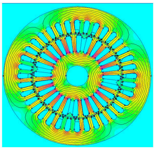
Figure 1.
Cross section of Induction motor.
To mitigate noise and harmonic distortions during startup and ensure smoother acceleration, the rotor is designed with circular conductors aligned with the motor axis. An accurate representation of the rotor’s electrical characteristics, including any inherent asymmetries, necessitates a comprehensive analysis of the rotor cage topology. Therefore, employing an optimal modeling approach is essential to achieve high fidelity in simulation and performance evaluation.
2.3. Optimizing Squirrel-Cage Induction Motor Parameters Through FEMM and MATLAB
To enhance the efficiency of an induction motor (IM) by reducing losses, it is essential to update both its mechanical and electrical parameters. In this study, the Finite Element Method Magnetics (FEMM4.2) software and MATLAB/Simulink2022b were utilized to determine the updated parameters. The methodologies employed for this parameter extraction are outlined below. A finite element (FE) model of the squirrel-cage IM was developed and analyzed using FEMM, as detailed in Table 2.

Table 2.
Experimental validation.
The primary objective was to improve the motor’s efficiency by accurately determining its electrical parameters. Additionally, a MATLAB/Simulink model was employed to further analyze the system’s performance and validate the results. An important feature of the stator is its slot shape, as illustrated in Figure 2. The stator inductance was computed by simulating the model across a range of rotor speeds and stator currents. Specifically, the stator inductance was identified at rotor speeds of 2, 5, 12, and 25 rad/s. A similar approach was adopted for the rotor, where the stator current gradually increased from 0 to 50 A while evaluating the corresponding rotor inductance at the specified speeds. Furthermore, key parameters such as the rotor time constant and the magnetic dispersion coefficient were estimated under varying operating conditions.
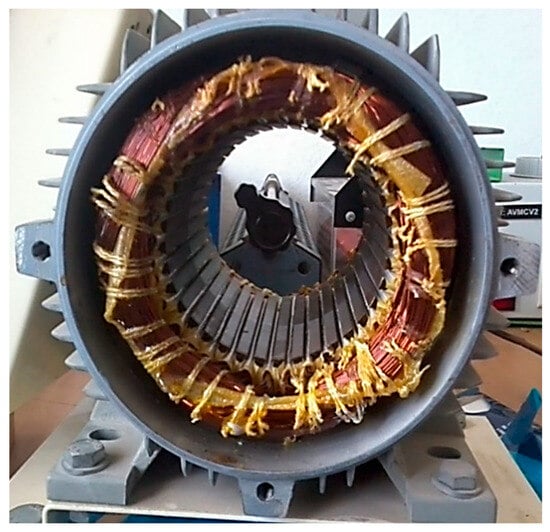
Figure 2.
Stator winding of the IM.
These findings provide critical insights into the electrical characteristics of the IM and facilitate the optimization of its performance by minimizing losses. The results from FEMM and MATLAB/Simulink contribute to the development of an enhanced IM model with improved efficiency.
3. Experimental Validation of the IM Model
This section presents the experimental findings of the study. The simulation results were experimentally validated using a dedicated test bench designed to assess efficiency improvements in the induction motor. This setup primarily consists of an 1800 W, three-phase, single-cage asynchronous motor (Siemens M1), mechanically coupled with a powder brake that serves as a resistive load. The powder brake is controlled by a continuous voltage source, enabling precise regulation of the braking torque, as illustrated in Figure 3. To evaluate the motor’s performance under various operating conditions, the system was tested across different stator current levels and rotor speeds. This approach facilitated a comprehensive analysis of motor behavior, enabling a close agreement between the finite element model (FEM) simulations and the experimental data. The controlled braking mechanism facilitated stable load conditions, thereby enhancing the reliability of the measured parameters. The rotor-material optimization in our study was achieved by employing a copper-aluminum alloy for the rotor windings, which was selected to reduce resistive (Joule) losses when compared to conventional aluminum windings. In addition, we introduced a new form of rotor slot geometry, specifically designed to further minimize harmonic losses and enhance efficiency.
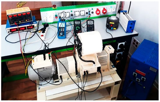
Figure 3.
Experimental validation setup.
The results obtained from these experiments provided valuable insights into the loss reduction and efficiency improvement strategies for the induction motor, validating the effectiveness of the optimized motor parameters derived from simulation. Figure 4 illustrates the copper losses in both the optimized model and the classical model. This experimental framework also enabled further refinement and enhancement of the simulation model, ensuring its accuracy in predicting real-world performance. Figure 5 shows a comparison between the losses in classic and optimized induction motors. As illustrated in Figure 4 and Figure 5, the comparative analysis demonstrates that the combination of an optimized slot design and improved rotor material results in a significant reduction in rotor losses relative to the standard aluminum winding configuration. These modifications collectively contribute to the enhanced performance and efficiency of the induction motor. Figure 6, Figure 7, Figure 8, Figure 9, Figure 10 and Figure 11 present the performance characteristics of the induction motor under varying available power conditions. The graphs depict key parameters, including power factor, slip, stator current, torque, rotational speed and efficiency, as functions of available power. These results provide a comprehensive understanding of the performance characteristics of the analyzed electrical machine. A high-precision position encoder with a resolution of 5000 steps per revolution (equivalent to 0.072°) is integrated into the system to capture real-time data on the motor’s angular position. Additionally, a stabilized power supply ensures a constant voltage supply to the motor, which is coupled to a controlled powder brake.
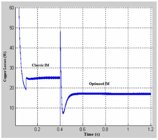
Figure 4.
Comparison of losses between the optimized model and the classical model.
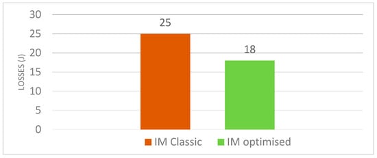
Figure 5.
Comparative analysis of Rotor Joules Losses using Bar Chart representation.
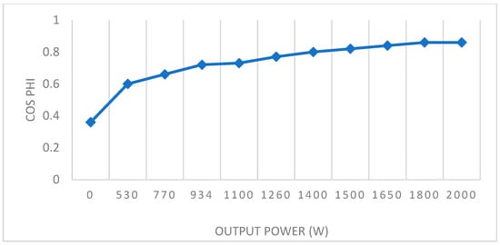
Figure 6.
Power Factor Variation as a Function of Output Power.
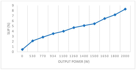
Figure 7.
Slip Variation as a Function of Output Power.
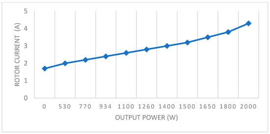
Figure 8.
Rotor current Variation as a Function of Output Power.
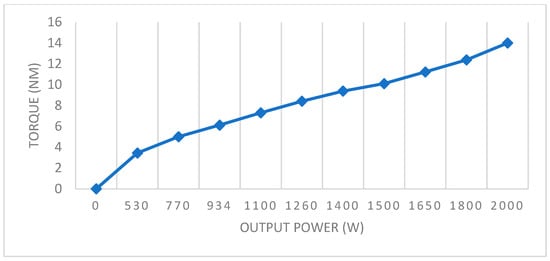
Figure 9.
Torque with the speed (in red is the experiment motor).
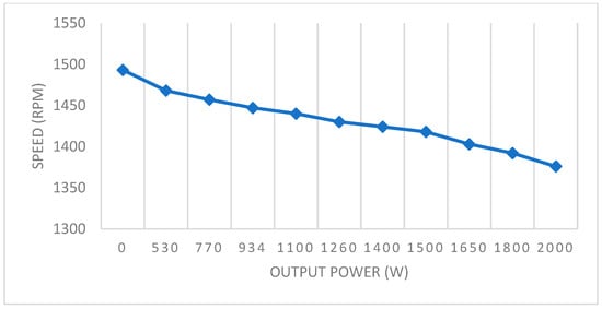
Figure 10.
Speed Versus Output power characteristics.
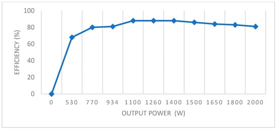
Figure 11.
Efficiency variation as a Function of Output Power.
This setup enables precise control of the braking torque, facilitating accurate assessment and validation of the motor’s performance under varying operational conditions. The brake functions as a load pair used in durability tests. After the transient phase, the electromagnetic torque stabilizes at its nominal value of 14 Nm, as illustrated in Figure 9. This stable electromagnetic torque indicates that the electrical machine operates efficiently and consistently. The machine’s performance can be further analyzed by examining the relationship between torque and other variables, such as speed and current. The no-load rotational speed was 1493 rpm, while the full-load speed was 1375 rpm, as shown in Figure 10.
Torque and speed are generally inversely related to electrical machines, particularly in induction motors. When load increases, torque increases, but speed decreases slightly due to slip. At full load, the speed is marginally lower than at nominal conditions, indicating a slight reduction in efficiency. However, this reduction remains within an acceptable range and does not significantly impact on the overall performance of the machine. The relationship between torque and speed was analyzed to compare the characteristics of the model obtained through the finite element method with the physical machine as shown in Figure 12.
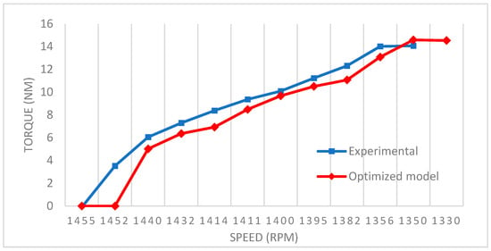
Figure 12.
Torque vs. speed: Experimental and Optimized Model Results (Red: Optimized Model, Blue: Experimental).
The results presented in this section demonstrate a strong correlation between the findings obtained through simulation and those derived from the experiment. The comparison of torque, speed, and efficiency characteristics indicates that the simulated model closely replicates the behavior of the physical machine, validating the accuracy of the finite element method used in the analysis.
Minor deviations observed between experimental and simulated results can be attributed to factors such as manufacturing tolerances, measurement uncertainties, and losses not fully accounted for in the simulation. However, these variations remain within an acceptable range, confirming the reliability of the optimized model in predicting the machine’s performance. The close agreement between both sets of results highlights the effectiveness of the proposed modifications and optimization techniques in improving the overall efficiency and performance of the machine.
4. Control and Regulation (Closed Loop) Based on Speed and Flux Using Sliding Mode
4.1. Sliding Mode Control
Sliding Mode Control (SMC) is a robust control technique widely used to address control challenges in dynamic systems. It has attracted significant attention due to its ability to handle nonlinear, uncertain, and complex systems effectively. Various control methodologies, such as Variable Structure Control (VSC) and SMC, have been applied across diverse domains, including stochastic systems, large-scale and infinite-dimensional systems, discrete-time models, multiple-input multiple-output (MIMO) systems, and nonlinear systems. Sliding Mode Control (SMC) operates by employing a discontinuous control signal that forces the system states to “slide” along a predefined surface, known as the sliding surface. This mechanism enables the system to maintain desired performance characteristics even in the presence of uncertainties and disturbances. This approach is particularly beneficial in achieving robust and high-performance regulation in nonlinear systems [27]. In this study, SMC is implemented with similar parameter considerations as those used in Field-Oriented Control (FOC). The objective is to develop a sliding mode controller that inherits the advantages of FOC with enhanced stability and robustness. The control strategy determines the optimal stator voltage vector, ensuring that both the stator flux linkage and the rotor speed remain within the desired limits [28].
The design of SMC typically involves two main phases. First, a switching surface is designed, ensuring that once the system state reaches this surface, the system response exhibits the desired characteristics. Second, a control law is established to satisfy the reaching condition, ensuring that the system states converge to the sliding surface within finite time, maintaining system stability and robustness against uncertainties [29].
4.2. Flux Regulation
By considering the first and third equations in Equation (1), we obtain the following expressions:
To keep things simple, we specify the process of error as follows:
where is the flux magnitude reference and is it estimated from the measured value of current by using the first equation in Equation (1).
The sliding mode flux surface is defined as
Taking the derivative of the Equation (11) and substituting Equations (9) and (10), we obtain
Substituting and of Equation (1) in Equation (11) yields:
And the new control function is
is the equivalent control that can be obtained by solving Equation (12):
The function is the discontinuous term employed to eliminate the influence of the uncertainties, which usually are composed of unpredictable parameter variations, external load disturbances, unmodeled and nonlinear dynamics, etc.
Note that the better choice of and allow for satisfying the sliding condition.
4.3. Speed Regulation
The equations used for angular speed regulation are written as follows:
From the above equation we write
The elimination of the state variable gives the following differential equation in
We remark that the mechanical load torque is expected to be a slowly varying function over time.
where represents the control input.
The error in the angular speed is written as
In this case, represents a positive constant.
Using Equation (23), the derivative of Equation (24) can be as follows:
The equivalent control is defined by the following expression:
And discontinuous control is:
Note that the better choice of and allow for satisfying the sliding condition. To improve the performance of the sliding mode controller, better constants (, ) and gains (, ) must be chosen. In this scenario, the metaheuristic optimization method, which is detailed below, can be used to find the ideal constants for sliding mode controller parameters.
5. Ant Colony Optimization (ACO) for Enhancing Sliding Mode Field-Oriented Control
Ant Colony Optimization (ACO) is a widely recognized metaheuristic optimization algorithm that has demonstrated remarkable effectiveness in solving combinatorial optimization problems (COPs) [30]. The algorithm is inspired by the foraging behavior of ants, which collectively identify shortest paths between their nest and food sources through indirect communication via pheromone deposition. Initially, ants explore random paths; as they traverse these routes, they deposit pheromones, that subsequently attract other ants to follow the same trajectory. Over time, the accumulation and evaporation of pheromones reinforce the optimal path, facilitating convergence to an efficient solution [31]. ACO has been widely used in control system tuning, particularly in nonlinear and dynamic systems such as induction motor drives. The primary advantage of ACO is its ability to identify optimal parameter sets through a distributed probabilistic search process, which is particularly beneficial in applications demanding precise gain tuning, such as Sliding Mode Field-Oriented Control (SM-FOC).
In this study, ACO is employed to optimize the tuning parameters of the Sliding Mode Field-Oriented Control (SM-FOC) for an induction motor, specifically refining the proportional and integral gains (, ) as well as the tuning constants (, ). The objective function is formulated based on speed tracking errors to minimize deviations and enhance control performance. The optimization process is governed by an improved ACO algorithm that integrates an elitist strategy to accelerate convergence and prevent premature stagnation [32]. By leveraging the adaptability and self-organizing capabilities of ACO, the optimized SM-FOC achieves enhanced robustness, improved dynamic response, and reduced steady-state error, thereby enhancing the overall efficiency of the induction motor drive system. The structure of the proposed combined control SM-FOC with ACO is presented in Figure 13.
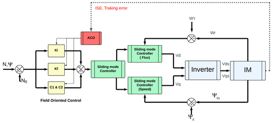
Figure 13.
Parameters tuning of SM-FOC with ACO.
Initialization: A population of artificial ants is deployed, each representing a candidate solution in the form of a parameter set (, , , ). The initial values are chosen based on prior knowledge from conventional tuning methods or heuristic estimations.
Solution Construction: Each ant iteratively constructs a complete solution by probabilistically selecting parameter values. The selection is influenced by pheromone trails and heuristic desirability functions, which guide the search toward promising regions of the solution space.
Evaluation: The fitness of each candidate solution is assessed using a cost function that quantifies the system’s performance. The cost function incorporates error metrics such as Integral of Time-weighted Absolute Error (ITAE) for speed tracking and flux regulation, as well as measures of robustness and chattering reduction in SM-FOC.
Pheromone Update: The pheromone levels are updated based on the quality of solutions found, reinforcing paths that lead to better performance. Solutions with higher fitness contribute more to the pheromone deposition, guiding subsequent iterations.
Convergence: The algorithm iterates until convergence criteria are met, such as a negligible change in fitness values across generations or a predefined iteration limit. The best-obtained parameter set is selected for implementation.
By integrating ACO into the control design, the SM-FOC scheme can achieve improved transient response, reduced steady-state error, and enhanced robustness against external disturbances and parameter uncertainties. This approach effectively addresses the tuning challenges associated with nonlinear control in induction motor drives, making it a valuable contribution to high-efficiency powertrain systems [33,34].
6. New European Driving Cycle
The New European Driving Cycle (NEDC) was developed to assess the emission levels and fuel economy of passenger vehicles in Europe. Vehicle emissions are a major contributor to atmospheric pollution in modern cities [35]. To offer uniform measures for regulatory and consumer information reasons, it was first introduced in the 1980s with the goal of representing typical urban and extra-urban driving situations [36]. In this study, the NEDC is employed to compare the emission levels and fuel economy of the optimized and non-optimized machines.
The structure of the NEDC comprises two main segments:
- Urban Driving Cycle (UDC): This segment simulates city driving conditions with low speeds and frequent stops, consisting of four repeated cycles, each lasting 195 s, totaling approximately 780 s.
- Extra-Urban Driving Cycle (EUDC): Following the UDC, this segment represents higher-speed driving conditions typical of suburban or highway scenarios, lasting about 400 s, with vehicle speeds reaching up to 120 km/h.
7. Results
7.1. Simulation Results
MATLAB/Simulink was selected for this study owing to its robust capabilities in vectorized system modeling and its intuitive graphical interface, which together enable the seamless integration of power electronics and control algorithms. This simulation environment facilitated precise modeling of the induction motor drive system, where the ode45 solver was employed under a fixed-step size to ensure numerical stability and repeatability. The system architecture consisted of a three-phase inverter with vector control for effective modulation of the induction motor, which was modeled using detailed Simulink blocks that captured its electrical, mechanical, and magnetic dynamics. A sliding mode controller governed speed and flux, delivering robust performance across diverse operating scenarios. Overall, this setup facilitated a comprehensive and realistic evaluation of the proposed control strategy’s dynamic effectiveness. As described in Section 2, the induction motor (IM) was powered by a three-phase inverter modeled using the standard “Three-Phase Inverter” block in MATLAB/Simulink. This inverter configuration comprised six IGBT switches and employed both vector control and pulse-width modulation (PWM) techniques [37]. The PWM switching frequency was set to 20 kHz. The proposed method was validated using an induction motor model with the parameters specified in Table 2. Figure 14 illustrates the simulation setup and system configuration. In this study, motor control was implemented in MATLAB/Simulink using Sliding Mode Control (SMC) with manually tuned parameters.
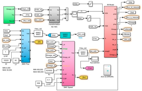
Figure 14.
SMC with FOC for IM model with MATLAB/SIMULINK.
The system’s performance was evaluated by analyzing the speed and flux responses of the motor. It was observed that manual tuning resulted in suboptimal performance, characterized by excessive settling time, large overshoot, and increased rise time as illustrated in Figure 15, Figure 16 and Figure 17. The plot presents the angular speed response of the induction motor under manually tuned sliding mode controller (SMC). The red dashed line represents the reference speed profile, which includes multiple setpoint changes to evaluate dynamic tracking performance, while the blue curve shows the actual measured speed response of the motor. Significant overshoot occurred following rapid increases in reference speed, along with considerable oscillations and prolonged settling time-particularly after the major speed reduction occurring around 8 s. Furthermore, the measured speed exhibits steady-state tracking errors and noticeable chattering, indicating suboptimal controller parameter selection. These results highlight the limitations of manual tuning and emphasize the need for optimization-based approaches to improve both transient and steady-state performance. These performance issues demonstrated that manual adjustment alone could not meet the fundamental criteria for effective sliding mode control. To enhance the control performance, the Ant Colony Optimization (ACO) technique was employed to optimize the controller parameters.
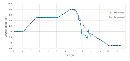
Figure 15.
Speed Response with manual tuning.
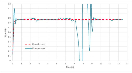
Figure 16.
Flux Response with manual tuning.
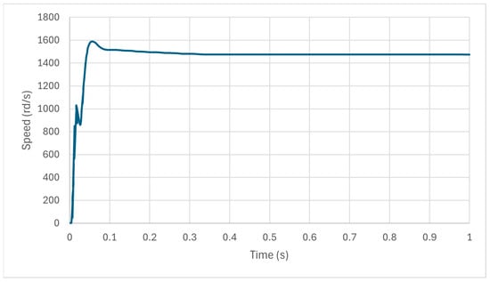
Figure 17.
Performance analysis of Induction Motor Speed Control with theoretical tuning.
The ACO-based tuning significantly improved the system’s response, resulting in reduced overshoots, faster rise time, and improved settling characteristics. Figure 18 and Figure 19 show the speed and flux responses, which were tuned using the ACO technique while accounting for the integral square error (ISE). Mathematical equation corresponding to the error:
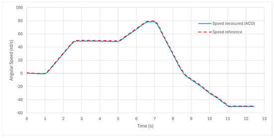
Figure 18.
Speed response with ACO tuning.
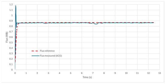
Figure 19.
Flux Response with ACO tuning.
Standard test scenarios for induction motor speed control typically include internal parameter variations to evaluate controller robustness.
The optimized controller demonstrated superior stability and tracking accuracy, making it more suitable for high-precision motor applications. The comparison between manually tuned and ACO-optimized SMC clearly highlights the effectiveness of metaheuristic optimization techniques in enhancing control strategies for electrical machines.
This study uses a trapezoidal reference speed profile to assess the drive system’s tracking performance. This approach enables a comprehensive assessment of the system’s ability to follow dynamic speed variations while maintaining stability and accuracy.
To further contextualize the proposed approach within the literature, a comparative analysis was conducted against previously reported implementations of Fractional-Order PID (FOPID) control for induction motor drives as shown in Figure 20. Although FOPID controllers generally achieve better tracking performance compared to conventional PID, they remain sensitive to parameter uncertainties and may require extensive tuning effort for different operating conditions. In contrast, the ACO-optimized SMC used in this study achieved a 99.74% reduction in speed error and 99.59% reduction in flux error compared to manual tuning, evaluated under both standard load conditions and the NEDC driving cycle. These findings demonstrate that, while FOPID offers improvement over traditional PID, the proposed SMC–ACO framework delivers superior robustness, adaptability, and dynamic performance—making it particularly suitable for electric vehicle powertrain applications.
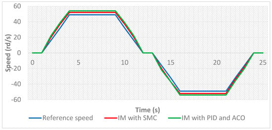
Figure 20.
Comparison of Speed Performance Using Sliding Mode Control and ACO-Based Optimization.
7.2. NEDC Validation
The proposed vehicle model was validated using the New European Driving Cycle (NEDC), which spans a total distance of 11,023 m over 1180 s, corresponding to an average vehicle speed of 33.6 km·h−1 (≈9.33 m·s−1). A sliding-mode speed controller was employed, with its gains automatically tuned using an ant-colony optimization (ACO) routine that minimized a tracking-error cost over the entire cycle while penalizing excessive control action. As illustrated in Figure 21, the estimated rotational speed (blue) closely follows the reference trajectory (green) across both stop-and-go urban segments and higher-speed extra-urban phases, covering a range of approximately 0–210 rad·s−1. The two trajectories are nearly superimposed, with only minor, short-lived deviations during sharp accelerations and decelerations. These results confirm negligible steady-state error and strong robustness to the pronounced speed fluctuations of the NEDC, underscoring the effectiveness of the SMC structure combined with ACO-based tuning. Table 3 presents the control parameters , , and obtained using both Sliding Mode Control (SMC) and Ant Colony Optimization (ACO) techniques. This table also includes the results for the Integral Squared Error (ISE) for speed and flux, which serve as key performance indicator for evaluating the control accuracy. The comparison of the parameter values highlights the impact of optimization techniques on the controller’s performance. The ISE values for both speed and flux are provided to quantify the effectiveness of the tuning methods, with lower ISE values indicating better tracking performance and reduced steady-state errors. The comparison highlights the significant improvements achieved with ACO-based tuning, demonstrating its effectiveness in refining controller parameters and enhancing overall system performance. The corresponding simulation results are presented to further validate these findings.
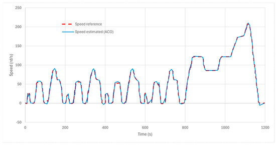
Figure 21.
NEDC speed tracking with ACO-tuned sliding-mode control: reference (red, dashed) vs. estimated speed (blue, solid) for the full 1200 s cycle.

Table 3.
Control parameters of manual and ACO tuning.
8. Conclusions
This study investigated the performance of an induction motor drive system controlled using Sliding Mode Control (SMC) and optimized using the Ant Colony Optimization (ACO) technique. The results showed that manual tuning of SMC parameters led to suboptimal performance, characterized by high overshoot, longer settling time, and increased rise time. To overcome these limitations, ACO was employed to optimize the control parameters (), resulting in a significant enhancement of system performance. The optimized control strategy achieved improved speed tracking, reduced flux and speed errors, and overall enhanced system stability, as evidenced by the lower Integral Squared Error (ISE) values for both speed and flux. The effectiveness of the proposed control strategy was further validated using the New European Driving Cycle (NEDC) test profile. Under NEDC conditions, the optimized system demonstrated substantial improvements compared to the baseline approach. Additionally, the optimized controller produced smoother speed tracking performance, with the Integral of Squared Error (ISE) for speed reduced by 99.74% and for flux by 99.59% relative to the manually tuned controller. These numerical results demonstrate the significant advantages of the proposed method for real-world electric vehicle applications.
Beyond performance enhancements, the improvements in motor efficiency directly contribute to increased battery life in electric drive applications, reducing energy consumption and extending the system’s operational lifespan. This optimization benefits not only industrial and automotive applications but also aligns with sustainability goals by minimizing energy losses, reducing thermal stress on components, and lowering maintenance costs. Moreover, by enhancing the efficiency of electrical machines, the proposed approach supports environmental sustainability by decreasing the overall carbon footprint associated with energy consumption. Efficient powertrain operation reduces energy demand, which in turn lowers greenhouse gas emissions, making the optimized system an environmentally responsible solution.
Overall, integrating ACO-based tuning into SMC offers a robust approach for achieving high-performance, energy-efficient motor control, with potential applications in sustainable transportation, renewable energy systems, and industrial automation. Future work could explore further refinements through hybrid optimization techniques and real-time implementation for enhanced adaptability in dynamic operating conditions.
Author Contributions
Conceptualization, Y.D. and W.A.; methodology, W.A., Y.D., F.H.M., F.A. and M.G.; software, Y.D.; validation, W.A., F.H.M., F.A. and M.G.; formal analysis, W.A., F.H.M., F.A. and M.G.; investigation, W.A.; resources, Y.D. and S.A.; data curation, W.A., F.H.M. and S.A.; writing—original draft preparation, Y.D.; writing—review and editing, W.A., F.H.M. and S.A.; visualization, W.A., F.A. and S.A.; supervision, W.A. and M.G.; project administration, W.A. and F.A. All authors have read and agreed to the published version of the manuscript.
Funding
This research received no external funding.
Data Availability Statement
The original contributions presented in this study are included in the article. Further inquiries can be directed to the corresponding author.
Conflicts of Interest
The authors declare no conflicts of interest.
References
- Ehsani, M.; Gao, Y.; Emadi, A. Modern Electric, Hybrid Electric, and Fuel Cell Vehicles: Fundamentals, Theory, and Design, 2nd ed.; CRC Press: Boca Raton, FL, USA, 2017; pp. 105–120. [Google Scholar]
- Foley, A.M.; Tyther, B.; Leahy, P.G.; McKeogh, E.J. Electric vehicles and energy storage—A case study on Ireland. In Proceedings of the 2009 IEEE Vehicle Power and Propulsion Conference (VPPC), Dearborn, MI, USA, 7–11 September 2009. [Google Scholar]
- Young, K.; Wang, C.; Wang, L.Y.; Strunz, K. Electric vehicle battery technologies—A review. Renew. Sustain. Energy Rev. 2016, 58, 1679–1697. [Google Scholar]
- Vetter, J.; Novak, P.; Wagner, M.R.; Veit, C.; Möller, K.-C.; Besenhard, J.O.; Winter, M.; Wohlfahrt-Mehrens, M.; Vogler, C.; Hammouche, A. Ageing mechanisms in lithium-ion batteries. J. Power Sources 2005, 147, 269–281. [Google Scholar] [CrossRef]
- Janek, J.; Zeier, W.G. A solid future for battery development. Nat. Energy 2016, 1, 16141. [Google Scholar] [CrossRef]
- Hu, X.; Feng, F.; Liu, Y.; Zhang, L.; Egardt, B. State estimation for advanced battery management: Key challenges and future trends. Renew. Sustain. Energy Rev. 2019, 114, 109334. [Google Scholar] [CrossRef]
- Zechmair, D.; Steidl, K. Why the Induction Motor could be the better choice for your electric vehicle program. World Electr. Veh. J. 2012, 5, 546–549. [Google Scholar] [CrossRef]
- Wang, S.; Li, Y.; Liu, Y. Rotor design to reduce secondary winding harmonic loss for induction motors in hybrid electric vehicle applications. In Proceedings of the 2016 IEEE Energy Conversion Congress and Exposition (ECCE), Milwaukee, WI, USA, 18–22 September 2016. [Google Scholar]
- Konuhova, M. Induction Motor Dynamics Regimes: A Comprehensive Study of Mathematical Models and Validation. Appl. Sci. 2025, 15, 1527. [Google Scholar] [CrossRef]
- Electric Motor R&D. Available online: https://www.energy.gov/eere/vehicles/articles/electric-motor-rd (accessed on 4 March 2025).
- Akhtar, M.J.; Behera, R.K. Optimal design of stator and rotor slot of induction motor for electric vehicle application. IET Electr. Syst. Transp. 2019, 9, 35–43. [Google Scholar] [CrossRef]
- Marfoli, A.; Di Nardo, M.; Degano, M.; Gerada, C.; Chen, W. Rotor Design Optimization of Squirrel Cage Induction Motor—Part I: Problem Statement. IEEE Trans. Energy Convers. 2021, 36, 1271–1279. [Google Scholar] [CrossRef]
- Krishnan, R. Electric Motor Drives: Modeling, Analysis, and Control; Prentice Hall: Upper Saddle River, NJ, USA, 2001; pp. 262–499. [Google Scholar]
- Holtz, J. Sensorless control of induction machines—With or without signal injection? IEEE Trans. Ind. Electron. 2006, 53, 7–30. [Google Scholar] [CrossRef]
- Utkin, V.; Guldner, J.; Shi, J. Sliding Mode Control in Electro-Mechanical Systems, 2nd ed.; CRC Press: Boca Raton, FL, USA, 2009; pp. 159–196. [Google Scholar]
- Hannan, M.; Lipu, M.; Hussain, A.; Mohamed, A. A review of lithium-ion battery state of charge estimation and management system in electric vehicle applications: Challenges and recommendations. Renew. Sustain. Energy Rev. 2017, 78, 834–854. [Google Scholar] [CrossRef]
- Zhang, Y.; Ma, H. Adaptive sliding mode control of induction motors based on artificial intelligence optimization. IEEE Access 2019, 7, 159711–159722. [Google Scholar]
- Mirjalili, S. Evolutionary Algorithms and Neural Networks: Theory and Applications, 1st ed.; Springer: Berlin/Heidelberg, Germany, 2019; pp. 15–55. [Google Scholar]
- Blum, C. Ant colony optimization: Introduction and recent trends. Phys. Life Rev. 2005, 2, 353–373. [Google Scholar] [CrossRef]
- Dorigo, M.; Stützle, T. Ant Colony Optimization, 1st ed.; MIT Press: Cambridge, MA, USA, 2004; pp. 153–204. [Google Scholar]
- Dorigo, M.; Maniezzo, V.; Colorni, A. Ant system: Optimization by a colony of cooperating agents. IEEE Trans. Syst. Man Cybern. Part B Cybern. 1996, 26, 29–41. [Google Scholar] [CrossRef]
- Bayoumi, E.H.E.; Soliman, H.M.; Lee, S. Ellipsoidal-Set Design of Robust and Secure Control Against Denial-of-Service Cyber Attacks in Electric-Vehicle Induction Motor Drives. Technologies 2025, 13, 289. [Google Scholar] [CrossRef]
- Gudey, S.K.; Malla, M.; Jasthi, K.; Gampa, S.R. Direct Torque Control of an Induction Motor Using Fractional-Order Sliding Mode Control Technique for Quick Response and Reduced Torque Ripple. World Electr. Veh. J. 2023, 14, 137. [Google Scholar] [CrossRef]
- Rtibi, W.; Yaich, M.; Hanini, W.; M’barki, L.; Ayadi, M. The Ant Colony Optimization Algorithm Application on the Speed Control of the Electrical Vehicle System Powered by the Five-Level NPC Inverter. In Proceedings of the 1st International Conference on Innovative Research in Applied Science, Engineering and Technology (IRASET), Meknes, Morocco, 12–13 March 2020. [Google Scholar]
- Azab, M. A Review of Recent Trends in High-Efficiency Induction Motor Drives. Vehicles 2025, 7, 15. [Google Scholar] [CrossRef]
- Rihar, A.; Nemec, M.; Lavrič, H.; Zajec, P.; Vončina, D.; Nedeljković, D.; Ambrožič, V.; Drobnič, K. Emerging Technologies for Advanced Power Electronics and Machine Design in Electric Drives. Appl. Sci. 2024, 14, 11559. [Google Scholar] [CrossRef]
- Jamoussi, K.; El Hajjaji, A.; Ouali, M. Robust Sliding Mode Control Using Adaptive Switching Gain for Induction Motors. Int. J. Autom. Comput. 2013, 10, 303–311. [Google Scholar] [CrossRef]
- Jamoussi, K.; Chadli, M.; El Hajjaji, A.; Ouali, M. Robust Fuzzy Sliding Mode Observer for an Induction Motor. J. Electr. Eng. Theory Appl. 2010, 1, 42–51. [Google Scholar]
- Ryvkin, S.; Schmidt-Oberm, R.; Steimel, A. Sliding Mode Control Technique for an Induction Motor Drive Supplied by a Three-Level Voltage Source Inverter. Ser. Elec. Energ. 2008, 21, 195–207. [Google Scholar] [CrossRef]
- Dhieb, Y.; Yaich, M.; Guermazi, A.; Ghariani, M. PID Controller Tuning using Ant Colony Optimization for Induction Motor. J. Electr. Syst. 2019, 15, 133–141. [Google Scholar]
- Borzabadi, A.H.; Mehne, H.H. Ant Colony Optimization for Optimal Control Problems. Sci. J. 2009, 4, 259–264. [Google Scholar]
- Spotvin, M.J.-Y. Ant Colony Optimization: Overview and Recent Advances. In Handbook of Metaheuristics, 3rd ed.; Springer: Berlin/Heidelberg, Germany, 2018; pp. 311–352. [Google Scholar]
- Kanthi Mathew, K.; Abraham, D.M.; Harish, A. Speed regulation of PMSM drive in electric vehicle applications with sliding mode controller based on harris Hawks optimization. e-Prime Adv. Electr. Eng. Electron. Energy 2024, 9, 100643. [Google Scholar] [CrossRef]
- Bendjedia, M.; Tehrani, K.A.; Azzouz, Y. Design of RST and fractional order PID controllers for an induction motor drive for electric vehicle application. In Proceedings of the 7th IET International Conference on Power Electronics, Machines and Drives (PEMD 2014), Manchester, UK, 8–10 April 2014; pp. 1–8. [Google Scholar] [CrossRef]
- Tzirakis, E.; Pitsas, K.; Zannikos, F.; Stournas, S. Vehicle emissions and driving cycles: Comparison of the Athens Driving Cycle (ADC) with ECE-15 and European Driving Cycle (EDC). Glob. NEST J. 2006, 8, 282–290. [Google Scholar]
- Safdari, M.; Ahmadi, R.; Sadeghzadeh, S. Numerical and experimental investigation on electric vehicles battery thermal management under New European Driving Cycle. Appl. Energy 2022, 315, 119026. [Google Scholar] [CrossRef]
- Alawieh, H.; Tehrani, K.A.; Azzouz, Y.; Dakyo, B. A new active common-mode voltage elimination method for three-Level Neutral-Point Clamped inverters. In Proceedings of the IECON 2014—40th Annual Conference of the IEEE Industrial Electronics Society, Dallas, TX, USA, 29 October–1 November 2014; pp. 1060–1066. [Google Scholar] [CrossRef]
Disclaimer/Publisher’s Note: The statements, opinions and data contained in all publications are solely those of the individual author(s) and contributor(s) and not of MDPI and/or the editor(s). MDPI and/or the editor(s) disclaim responsibility for any injury to people or property resulting from any ideas, methods, instructions or products referred to in the content. |
© 2025 by the authors. Published by MDPI on behalf of the World Electric Vehicle Association. Licensee MDPI, Basel, Switzerland. This article is an open access article distributed under the terms and conditions of the Creative Commons Attribution (CC BY) license (https://creativecommons.org/licenses/by/4.0/).