1. Introduction
Wireless power transmission technology integrates power electronic power conversion technology, electromagnetic conversion technology, and modern control technology. It uses electromagnetic fields as a medium to achieve direct electrical contact free transmission of electrical energy from the transmitting end to the receiving end. It has the advantages of safety, convenience, and easy implementation of intelligent operation, which can effectively overcome the problems brought by wired transmission methods [
1].
In wireless power transmission systems, the circuit is generally operated in a resonant state to ensure the transmission power and efficiency of the system. System tuning control mainly includes frequency modulation control and impedance network parameter adjustment control (such as inductance, capacitance, etc.). The front-end rectification mostly uses uncontrolled diode bridge rectification to achieve AC/DC conversion [
2]. However, due to the nonlinearity of the diode, this rectification method will bring a large number of harmonics to the charging system. The uncontrollability of the diode will cause the output DC voltage to change with the load and mutual inductance. To control the output voltage, a DC-DC link is usually added after the rectification link, making the circuit structure more complex and increasing the volume and cost of the device. Therefore, in recent years, more and more infinite energy transmission systems are using Pulse Width Modulation (PWM) rectification as the front-end rectifier. Compared with traditional diode shift or phase-controlled rectification methods, this circuit topology has advantages such as high input power factor, sinusoidal variation of grid-measured current, and the ability to achieve bidirectional energy flow, making it a hot topic of attention and research in the academic community in recent years.
In recent years, power electronics research has been strongly recommended for industrial applications in areas such as high power density, high power factor, high efficiency, low current distortion, and simple control schemes. Traditional diode rectifiers or phase-controlled rectifiers have the characteristics of simple structure and low cost. However, they have an inherent drawback, which is that as the emission angle increases, the power factor decreases while the line current harmonics are relatively high. In order to overcome the above problems, several circuit topologies of single-phase switching mode rectifiers (SMRs) with low current distortion and unified power factor have been proposed in the past few years [
3,
4]. These circuit configurations are based on a full bridge diode rectifier, followed by a boost, buck-boost, or CUK converter. Single-phase full-bridge [
5] and half-bridge [
6] SMR circuit configurations have capabilities such as bidirectional power flow, reactive power control, and high power factor. Among these circuit topologies, single-phase unidirectional AC/DC converters with boost topology are widely used as front-end power factor pre-regulators due to their excellent performance. In addition, it is also recommended that three-phase, three-level PWM rectifiers [
7] with unidirectional power flow to reduce voltage stress and power loss on the power switch. Six power switches are used in this topology structure. For single-phase three-level AC/DC converters, the number of power devices can be significantly reduced. The single-phase, three-level PWM rectifier uses two power switches. The rated voltage of the power switch is half of the DC bus voltage. The disadvantage of these schemes is that the control scheme is complex, or there is no experimental testing.
Compared with the traditional phase-shifting rectification method, the PWM rectifier has the advantages of high input power factor, sinusoidal variation of network measurement current, and the ability to achieve bidirectional energy flow. Therefore, it has become a hot topic of attention and research in the academic community in recent years, and some better results have been obtained [
6,
7,
8,
9,
10,
11,
12]. Ref. [
8] described a novel control strategy of direct power-control-based voltage-source pulse width modulation (PWM) rectifier-inverter. The key to this strategy is the direct selection of a switching state of the PWM rectifier-inverter on the basis of instantaneous power errors. In Ref. [
9], three-phase rectifier systems without connection of the neutral wire were characterized by the coupling of the phase input currents, and a three-phase Delta-switch rectifier circuit is used for analysis and a detailed model of the rectifier system is derived where the cross-couplings are visible. The model is subsequently used to evaluate the cross couplings, and three independent current controllers are designed. In [
10], the authors proposed an improved model of predictive direct power control (MPDPC) for PWM rectifiers to solve highly distorted under unbalanced network conditions. Ref. [
9] developed a new AC voltage sensorless control scheme for the three-phase pulse-width modulation rectifier, and a new startup process to ensure a smooth starting of the system was also proposed. Ref. [
10] gave the AC side voltage compensation parameter to improve the power factor and reduce the total harmonic distortion. In Ref. [
11], the authors developed an enhanced model-free predictive control (MFPC) to eliminate the stagnant current variation update for PWM rectifiers.
Among them, in three-phase voltage source PWM rectifiers, a double closed-loop control method of voltage outer loop and current inner loop is commonly used. This method has a simple control structure, is easy to implement, and is widely favored in engineering applications. However, during the transition from diode rectification to PWM current, there are significant surge currents and over-voltage, which pose certain hazards to the safe operation of the equipment [
12]. In recent years, various start-up inrush current suppression methods on the PWM rectifier have been proposed, which are mainly classified into active control method and passive control method [
13,
14]. As well known, the passive control method can partly suppress the inrush current. However, the suppression is only taken passively after the inrush current has been generated [
15,
16,
17]. To compensate for this deficiency, an active control method is proposed to take suppression measures in advance. Based on the injecting method [
16,
17] effectively suppressed the generation of inrush currents. However, applying the methods in [
16,
17], one needs to introduce more ancillary equipment, resulting in expensive costs. Apart from these, other active control methods add the transition procedure between the uncontrollable rectification state and the controllable rectification state of the PWM rectifier [
18,
19,
20,
21,
22]. It should be pointed out that the above control can only suppress inrush currents partially, and the start moment of the converter cannot be suppressed especially.
In fact, the main reason for the surge overcurrent during PWM rectifier startup is that the bus voltage is too low during startup, leading to a rapid increase in active current command. Therefore, the fundamental method to suppress the surge current is to reduce the active current command during startup. Ref. [
20] reduced the output of the voltage outer loop by setting the DC bus voltage command to the superposition of the initial voltage value and graceful curve. In Ref. [
21], the authors adopted a segmented starting method. Namely, during the starting stage, the control bus voltage monotonically increases, and when the bus voltage reaches 0.9 times of the command voltage, it switches to PWM rectification. Ref. [
23] divided a cycle into six sectors during the startup process by using a single-phase BOOST circuit to control the duty cycle of the single-phase circuit and the speed of bus voltage rise so that the voltage and current surge during the startup process are slowed down.
The above measures have achieved certain results in suppressing PWM startup surge, but the specific engineering implementation methods have not been discussed in detail, especially when switching from the transition process to normal operation. Improper control can cause a secondary current surge in the system. On the basis of discussing the principle of generating startup surge current, this article introduces the engineering implementation method of the startup process, and a comparative simulation analysis and experimental verification are conducted on the proposed method. The experiment proved that the separation of the voltage loop proportional loop and the current loop integral loop not only greatly reduces the voltage surge during startup but also effectively avoids the generation of a secondary current surge.
2. Modeling and Control of Voltage Source PWM Rectifier
The main circuit topology of the voltage source PWM rectifier is shown in
Figure 1.
Before analyzing the mathematical model of the rectifier, we present the following assumptions:
Remark 1. Assumption A1 ensures that a three-phase ideal symmetrical power supply has three identical voltage waves that are 120 degrees apart in phase. This symmetry means that the voltage and current waveforms are identical across all three phases, resulting in balanced loading and reduced harmonic distortion.
Remark 2. Under the assumption, the switching devices are all ideal switches, which means that they have no inherent resistance or loss when switching on or off. In other words, they completely isolate the circuit when closed and have no impedance when open. This statement has important implications for the behavior of circuits containing these switches. For example, if a circuit contains an ideal switch, it can be used to control the flow of current between two points in the circuit, without any energy loss due to the switch itself. This allows for efficient control and manipulation of electrical devices, as well as reducing the overall energy consumption of the system.
Remark 3. Dead zone refers to a situation where a change in a physical quantity (such as voltage, current, etc.) within a specific range cannot cause a change in another physical quantity (such as switch state, equipment working state, etc.). In circuits, dead zones typically occur between components such as controllers, sensors, and actuators. Due to the existence of dead zones, the circuit system may not function properly under certain working conditions, resulting in performance degradation, system instability, and other issues. On the one hand, dead zones can have a negative impact on the performance of circuit systems. For example, in fields such as switching power supplies and motor control, dead zones may cause fluctuations in output voltage or speed, which in turn affects the stability and efficiency of equipment. In addition, dead zones may also cause the system to be insensitive to input signals, making it difficult to achieve precise control.
The mathematical model in the
and
rotating coordinate system using grid voltage orientation is expressed as:
where
is a unipolar binary switching function,
is the DC bus voltage,
,
,
, and
are the current, and the grid voltage of the AC side in the synchronous d and q rotating coordinate systems respectively,
and
are equal to the rectifier side voltages
and
.
By controlling
and
, the control of the rectifier side voltages
and
can be achieved, thereby controlling the network measurement current and DC side voltage. The control structure diagram is shown in
Figure 2:
3. Reasons for the Generation of Starting Impulse Current
When the system operates at a unit power factor and adopts a
d-axis orientation, the
d-axis component of the grid current is constant, and the
q-axis component is zero. The system (1) can be equivalent to:
If both the current inner loop and the voltage outer loop use PI controllers, that is:
The control equation obtained from Equations (2) and (3) above is:
where
is the peak value of phase voltage.
are respectively the proportional coefficient and integral coefficient of the voltage outer loop PI controller;
are the ratio coefficient and integration coefficient of the active current inner loop PI controller, respectively;
are the proportional coefficient and integral coefficient of the reactive current inner loop PI controller, respectively.
From Equations (2) to (4), one can obtain that
d-
q decoupled double closed loop control block diagram, see in
Figure 3 below.
The voltage outer loop PI controller is used to follow the DC bus voltage
, and its output is used as the given value of the active current
in the current inner loop. The main function of the current inner loop PI controller is to follow the given value of the current, that is, to follow the active current value
and the reactive current value
. Through
d-
q decoupling, a reference control voltage is generated, and the control voltage is divided by the bridge arm gain
to generate modulation ratios
and
. The relationship between the two is shown in Formula (5):
After the modulation ratios
and
are changed by 2s-3r, three-phase modulation waves are generated, which are modulated with three-phase carrier waves to generate driving signals for power devices, namely:
are the control signals of the switching tubes for the three-phase bridge arms, respectively, is the phase angle of the grid voltage space vector, which can be obtained through phase locking of the grid voltage.
The rectifier is in an uncontrollable rectification state before restarting, so the initial value of the DC bus voltage is a fixed value:
is the peak phase voltage on the grid side. In order to achieve unit power factor rectification, the set value of the DC bus voltage must be greater than the initial value of the uncontrolled rectification state. Generally, it is selected:
Therefore, the process of starting the rectifier is the process of the DC bus voltage rising from the uncontrolled rectification state to the set voltage .
If L and R are ignored, it can be seen from Equation (2) that the rate of change of current is only related to the voltage difference between the two ends of the grid side inductance. When using unit power factor rectification, the reactive current is given as 0, so the reactive current component will not generate a starting impulse current. Assuming that at startup, the given DC bus voltage is much higher than the actual DC voltage. After several cycles of voltage loop adjustment, the output active current reaches saturation output, and the deviation of the active current in the current inner loop will rapidly increase, even reaching integral saturation. At this point, the current inner loop will decrease and increase the actual value of the inner loop current. In addition, the DC voltage dynamic response is slower, resulting in a smaller actual , which further increases the actual output current and may exceed the given current command . At this time, the controller will increase to suppress the increase of active current. If the voltage loop response is slower, can eventually reach saturation. Although reaches saturation, if , there is still a voltage difference between the two ends of the inductor on the AC side such that the current inner loop PI regulator will lose its current regulation ability, causing the active current to continue to increase and develop a significant current surge.
As the active current increases, the DC voltage will continue to increase. When , the voltage at both ends of the inductor will be 0, and the active current will begin to decrease. The PI regulator in the current inner loop will reactivate, and under the control of the voltage and current loops, both the active current and DC voltage will eventually stabilize.
4. Suppression Methods for Initiating Shocks
From the above analysis, it can be seen that the current surge and voltage surge during the start-up of PWM rectifiers are concomitant. Due to the slower response speed of the voltage outer loop compared to the current loop, the current loop reaches saturation and loses control during the voltage rise process, and the duty cycle of the rectifier bridge power device reaches its maximum, resulting in grid side current surge. To reduce the startup impulse of PWM rectifiers, it is necessary to avoid the current inner loop controller losing control or reduce the time of losing control.
This article proposes a novel segmented control method that can effectively avoid the loss of control in the current inner loop, thereby reducing the starting impulse current. The specific implementation method is shown in
Figure 4. Where,
is the active current command,
is the reactive current command,
is the bus DC voltage command.
When starting, first separate the inner current loop and the outer voltage loop. At this time, the set value of the active current is selected as the calculated active current in the uncontrolled rectification state. According to the instantaneous power theory, there is a certain fluctuation in the active current at this time. The maximum value of the active current at this time can be selected as the set value of the active current in the starting state. At this point, the voltage outer loop is not working. When the DC bus voltage is basically stable, the set value of the active current slowly increases. If the actual value of the bus voltage rises to nearly ninety percent, by integrating the DC voltage outer loop into the control system, we can effectively solve the problem of the slow response of the DC voltage outer loop, which leads to saturation of the current inner loop and reduces the starting impulse of the current.
In the meantime, to avoid secondary impact caused by the connection of the DC voltage outer loop to the system, the following measures are adopted to prevent the voltage outer loop from generating integral saturation. Without loss of generality, assume that the voltage outer loop is connected to the system; the actual value of the active current
satisfies the following equation:
where
and
are the proportional and integral coefficients of the DC voltage outer loop, respectively, and
is the initial values of the voltage integral accumulation of the voltage outer loop.
Choosing calculated from Equation (3) as the initial value of the voltage outer loop when connected to the system, one can ensure a smooth transition of the inner loop current command when connected to the voltage outer loop, thereby avoiding the occurrence of secondary shocks.
5. Simulation Analysis
To verify the effectiveness of the PWM rectifier start-up control strategy mentioned above, we design a simulation model as shown in
Figure 4 and give two comparison with traditional start-up control method in
Figure 5 and
Figure 6. The simulation parameters are given in
Table 1.
Based on the simulation model construction in
Figure 5, we give two comparative simulations (as shown in
Figure 6 and
Figure 7) between traditional control method and the starting control strategy of this paper. The waveforms of the rectified current during startup are shown in
Figure 6.
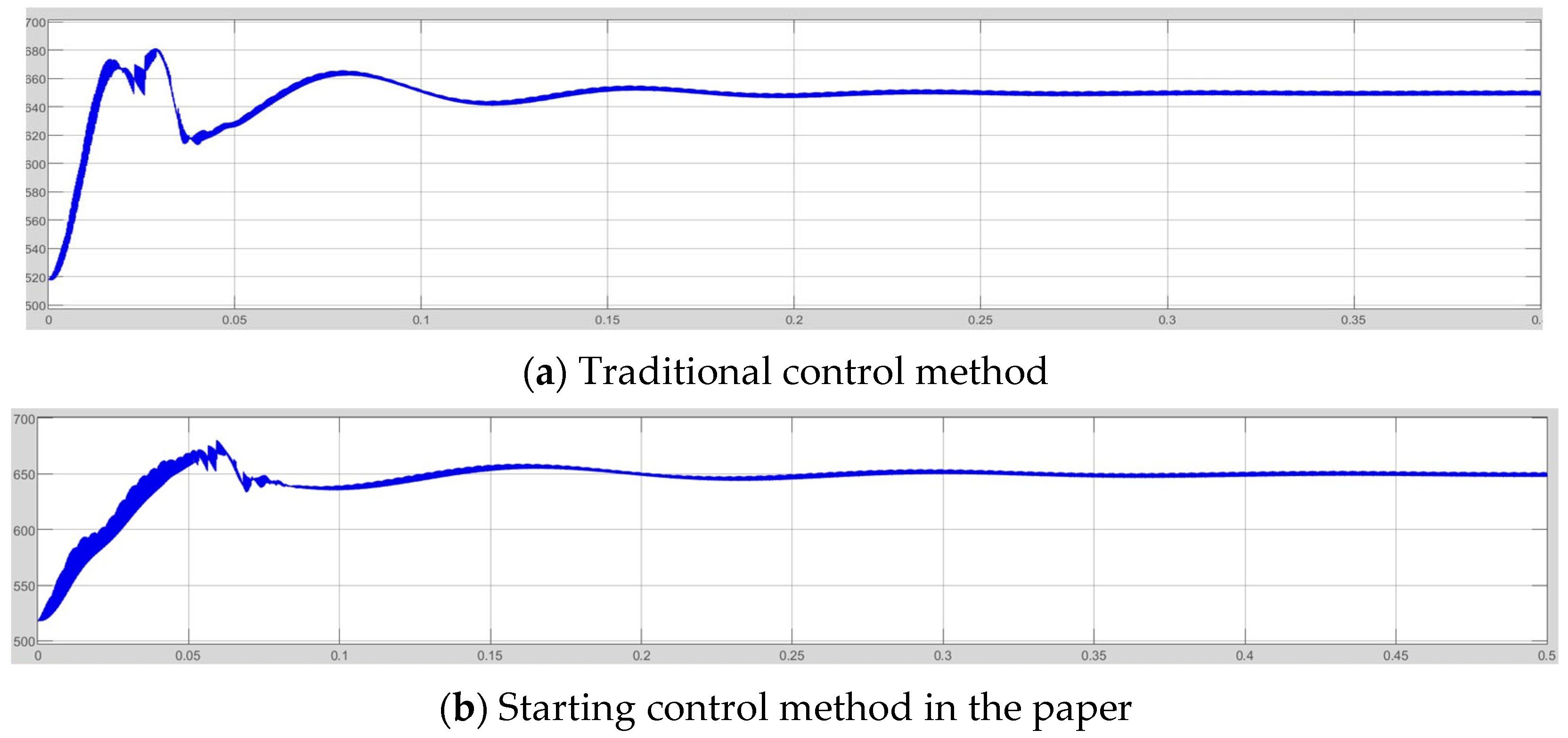
From
Figure 6, it can be seen that when starting with traditional methods, the surge current can reach 150 A, which is 3.75 times the normal operating current. After adopting the improved starting strategy designed in this article, the maximum surge current is 60 A, which is about 1.5 times the normal operating current, greatly reducing the starting current surge. In addition, after improving the control strategy, the start-up time was reduced from 0.15 s to 0.1 s. When the start-up process is over, both methods can work stably at the unit power factor state.
In addition, we also give the corresponding waveforms of DC voltage at startup, as shown in
Figure 6 below.
From
Figure 6, it can be seen that when the DC voltage is set to 650 V, the DC voltage can reach around 680 V, and there is a long oscillation time when starting with the traditional method. However, after adopting the control strategy described in this article, the maximum DC voltage during starting is around 660 V, and the oscillation time is also reduced. Therefore, after the improvement of the control method, the voltage overshoot at start-up and the DC voltage ripple at steady-state operation are greatly reduced.
6. Experimental Verification
To further validate the startup strategy described in this article, an experimental setup is designed, as shown in
Figure 8 below.
In the following, we give several experimental results by applying the above experimental setup.
The core controller uses TMS320F28335DSP, which was produced by TI, and the main circuit of the system uses an Infineon IGBT power module. The A/D sampling frequency is 3 KHz, and the bus voltage is set at 650 V. The simulation results are shown in
Figure 9,
Figure 10,
Figure 11 and
Figure 12. As shown in
Figure 9, it only takes about two grid cycles for the grid side current to be in the same phase as the power supply voltage during system startup. After being in phase, the current waveform has good sinusoidal characteristics, low harmonic content, and a small starting current impact, accounting for about 20 percent of the rated operating current.
The ratio of the current sampling and conditioning circuit is 45 A/V, and it can be seen from
Figure 9 that the current overshoot in the startup process is about 44% after the improved control method is adopted. Much less than 2 times the protection value, improving the security of the device.
Figure 10 shows the startup voltage waveform. It can be seen that the startup voltage rises smoothly, and there is no significant voltage surge or fluctuation at the switching point. The switching point is the moment when the voltage loop is connected to the current loop. The voltage overshoot during the entire startup process is only 9 V with an overshoot of 1.38 percent.
Figure 11 shows the waveforms of grid side voltage, current, and DC bus voltage during stable operation. It can be seen that the power factor of the equipment during stable operation is 1, which can achieve unit power factor rectification. Moreover, the DC bus voltage is stable and has little fluctuation.
Figure 12 shows the voltage, current, and DC bus voltage waveforms on the grid side when the load resistance suddenly changes from 75 Ω to 25 Ω. It can be seen that when the load suddenly changes, the grid side current and voltage can maintain good in-phase, and the grid side current can quickly recover the sine waveform with a short distortion time. After the DC bus voltage drops, the set value can be quickly tracked. When the load changes, the grid voltage and current are always at the same frequency and phase; that is, high power factor rectification is always maintained.


