Article

Research on the Multiple Capacitor Current Sharing of High-Current Receiving Coils in a Series–Series Wireless Charging System

1
School of Electrical Engineering, Shandong University, Jingshi Road 17923, Jinan 250061, China
2
School of Information Science and Electrical Engineering, Shandong Jiaotong University, Jinan 250357, China
3
Jinan EMag Electric Co., Ltd., Jingyi Road 88, Jinan 250061, China
*
Author to whom correspondence should be addressed.
World Electr. Veh. J. 2024, 15(2), 58; https://doi.org/10.3390/wevj15020058
Submission received: 8 December 2023 / Revised: 26 January 2024 / Accepted: 6 February 2024 / Published: 8 February 2024

Abstract

:
In order to improve wireless charging power and reduce heating problems, the optimal design of the high-current wireless charging coil has always been the research focus of wireless charging system research. This paper proposes a multi-branch and multi-capacitance current sharing method for series–series (SS) receiving coils. Firstly, the current sharing model with n branches that are connected parallel to multiple compensation capacitors is established. The current sharing situation of parallel coils with three branches and three capacitors with independently resonant compensation is analyzed. Then, the wireless charging system with the parallel coils of 48 V/100 A receiving coils is simulated. The results show that when one capacitor is used for compensation, the three-coil currents highly differ; when three capacitors are compensated independently, the three-coil currents are basically equal. The simulation results show that the current sharing method can effectively improve the charging power of the system and reduce the maximum temperature of the receiving coil, which proves the effectiveness of this method. Finally, through the experimental comparison, it is verified that the current sharing measure can make the current of each wire basically equal.

1. Introduction

In recent years, wireless power transmission technology has been increasingly used in industrial fields such as rail transit [1,2,3,4] and electric vehicles [5,6,7,8]. Resonant topology is the basis of the efficient transmission of wireless power systems. Reference [9] compares the advantages and disadvantages of different compensation topologies and also compares their load characteristics as well as their open-circuit and short-circuit performances. The magnetic coupling mechanism of the primary side and the secondary side is the most important part of the wireless power transfer system. In order to improve the performance of wireless power transmission, a lot of literature has carried out a lot of research on it. Reference [10] proposes using a DDQ coil and a BP coil to enhance the anti-offset ability, but this will use more copper and reduce the coupling coefficient. The H-core proposed in [11] can have higher tolerance and efficiency in a larger air gap, but the magnetic flux leakage is more serious. The cause of the AC resistance of the coil is analyzed and the calculation of the AC resistance is studied in reference [12,13]. Reference [14] analyzes the influence of increasing the coupling coefficient on the transmission performance of the system, points out that increasing the coupling coefficient can reduce the sensitivity of the system, and puts forward a method to optimize the coil to improve the coupling coefficient. The relationship between the coupling coefficient and the inner and outer radius of the coil is analyzed in [15], and it is concluded that there is a small relationship between the coupling coefficient and the inner radius of the coil; however, with the gradual increase of the inner radius, its influence on the coupling coefficient cannot be ignored in practical application. Reference [16] points out that mutual inductance is independent of wire diameter, puts forward a new method for calculating mutual inductance, which is verified through experiments, and provides certain methods to optimize the coupling coefficient when the size of the receiving coil is limited by space. The influence of the coupling mutual inductance parameters on the performance of radio energy transmission systems is analyzed in reference [17]. It is pointed out that increasing mutual inductance can improve system efficiency, and the optimization conditions are given. In this paper, a new, comprehensive evaluation index of the system is proposed, which considers many factors such as efficiency, cost, and so on. Modeling research on wireless charging systems has also been carried out. Reference [18] deeply studied the finite element modeling of a 5 KW system, provided calculation methods for power loss, equivalent circuits, and stray fields, and experimentally verified the obtained finite element simulation results, concluding that the error was less than 5%.
In order to increase the charging power, the high-current wireless charging coil can use multiple coils that are in parallel to improve the current level. Currently, a lot of research has been carried out on the application of multiple coils in the coupling mechanism. In [19], using multiple receiving coils is proposed to improve overall system efficiency, but it does not consider the influence of coupling between multiple coils on the secondary side of the system. In [20,21], through the study of the coupling effect between multiple receiving coils and multiple transmitting coils in the wireless charging system, it is concluded that the resonant frequency of the system shifts under the coupling effect. It is necessary to re-adjust the compensation network parameters to improve efficiency. In [22], a scheme using the parallel connection between double-layer coils on the original and secondary sides is put forward, the compensation capacitance of the current sharing coil is derived through the phase difference, and the current sharing effect is verified through experiments. However, a general model of the n coils that are in parallel is not deduced in it, and the expression of compensation capacitance is a little complicated in it too.
A high-current wireless charging system uses a high-power density coil, which has high loss and causes the coil temperature to rise. If the temperature of the system is too high, it will affect the material properties of the magnetic core, reduce the coupling of the primary and secondary side coils, affect the transmission efficiency of the system, and cause a lot of security risks [23,24,25]. The loss of the system is obtained through finite element simulation, and then the temperature of the coupling mechanism can be obtained through thermal simulation. Combined with the thermal simulation results, the coupling mechanism can be further optimized.
In this paper, the current sharing measure of multi-coils and multi-capacitors is proposed. First, the basic principle of the SS structure for wireless power transmission is deduced, then the current sharing model is derived for the parallel coils of the high-current wireless charging system, and the expression form of the compensation capacitor is obtained. Afterward, taking the parallel connection between the three coils as an example, the detailed current sharing equation is derived. The single capacitor compensation and the multi-capacitor compensation are simulated, and the simulation results are compared and analyzed to verify the effectiveness of the current sharing measure. The coils using the abovementioned two capacitance compensation methods are compared through disturbance simulation and thermal simulation, and the effect of current sharing measures on improving the anti-disturbance ability of the system and reducing the maximum temperature of the coil is analyzed. Finally, an experimental platform is set up to sample the current of each wire in the coil under two conditions as follows: no current sharing measures and current sharing measures. Furthermore, the effects of the current sharing measures are compared and verified.

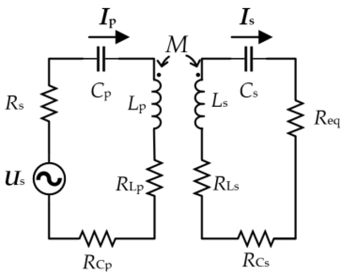
2. Principle of Wireless Power Transmission in a SS Structure

Figure 1 shows a schematic diagram of the SS structure for the wireless power transmission system. The DC power supply outputs a high-frequency AC voltage after passing through the inverter circuit. The primary side resonant circuit is composed of Cp and Lp, and the secondary resonant circuit is composed of Cs and Ls. Lp and Ls are energy transmission coils. RL and RC are the internal resistance of the inductor and capacitor, respectively. Ip and Is are the currents flowing through the primary and secondary coils, respectively. The alternating current is output through the SS compensation structure, which is passed through the uncontrollable rectification circuit composed of the diodes D1, D2, D3, and D4 and then filtered through the capacitor C0 to obtain a stable direct current I0 to supply power to the load RL. The output of the inverter is equivalent to an AC current source US and an AC source’s internal resistance Rs, and the rectifier and load are equivalent to Req in order to analyze its basic characteristics in which Req = 8 RL · (π2)−1 [26], as shown in Figure 2.
According to Figure 2 and Kirchhoff’s laws, the primary side current Ip and the secondary side current Is at resonance are obtained as follows:
I p = U S ( R Ls + R Cs + R eq ) ω 0 2 M 2 + ( R Lp + R Cp + R S ) ( R Ls + R Cs + R eq ) ,
I s = i ω 0 M U S ω 0 2 M 2 + ( R Lp + R Cp + R S ) ( R Ls + R Cs + R eq ) ,
where
ω 0 = 1 L p C p = 1 L s C s
If the internal resistance of the power supply, inductor, and capacitor is ignored, after simplifying Equations (1) and (2), the following current equation can be obtained:
I p = U S R eq ω 0 2 M 2
I s = i U S ω M
The simplified current equation can effectively reduce the difficulty of system parameter matching, and these two formulas are used to determine parameters such as that of coil inductance.
According to the equivalent circuit above and Equations (1) and (2), the efficiency of the SS structure is obtained, and the expression of this is as follows:
η = ω 0 2 M 2 R eq [ ω 0 2 M 2 + ( R Lp + R Cp + R S ) ( R Ls + R Cs + R eq ) ] ( R Ls + R Cs + R eq ) .
Ignoring the internal resistance of the power supply and capacitor, the efficiency can be expressed in the form of a quality factor, as shown in Equation (7) and through the quality factor that is shown in Equation (8).
η = 1 1 + 1 k 2 Q Lp Q s · 1 1 + R Ls R eq ,
Q Lp = ω L p R Lp , Q s = ω L s R Ls + R eq .
Qs is the quality factor of the receiving side. To improve efficiency, it is necessary to improve the value of the quality factor. However, in order to ensure the stability of the system, the quality factor of the receiving side should not exceed 10 as much as possible [27]. The load of the high-current wireless charging system is relatively small, and the inductance of the receiving coil should also be low in order to limit the value of Qs. To wind a receiving coil with a small inductance value that can withstand high currents, it is necessary to use multiple wires in parallel. However, the current inequality of multiple wires requires thicker wires, and the problem of local overheating of wires occurs. Therefore, it is necessary to study the current sharing measures among multiple wires.

3. Model of the Current Sharing of Coils and Efficiency Analysis

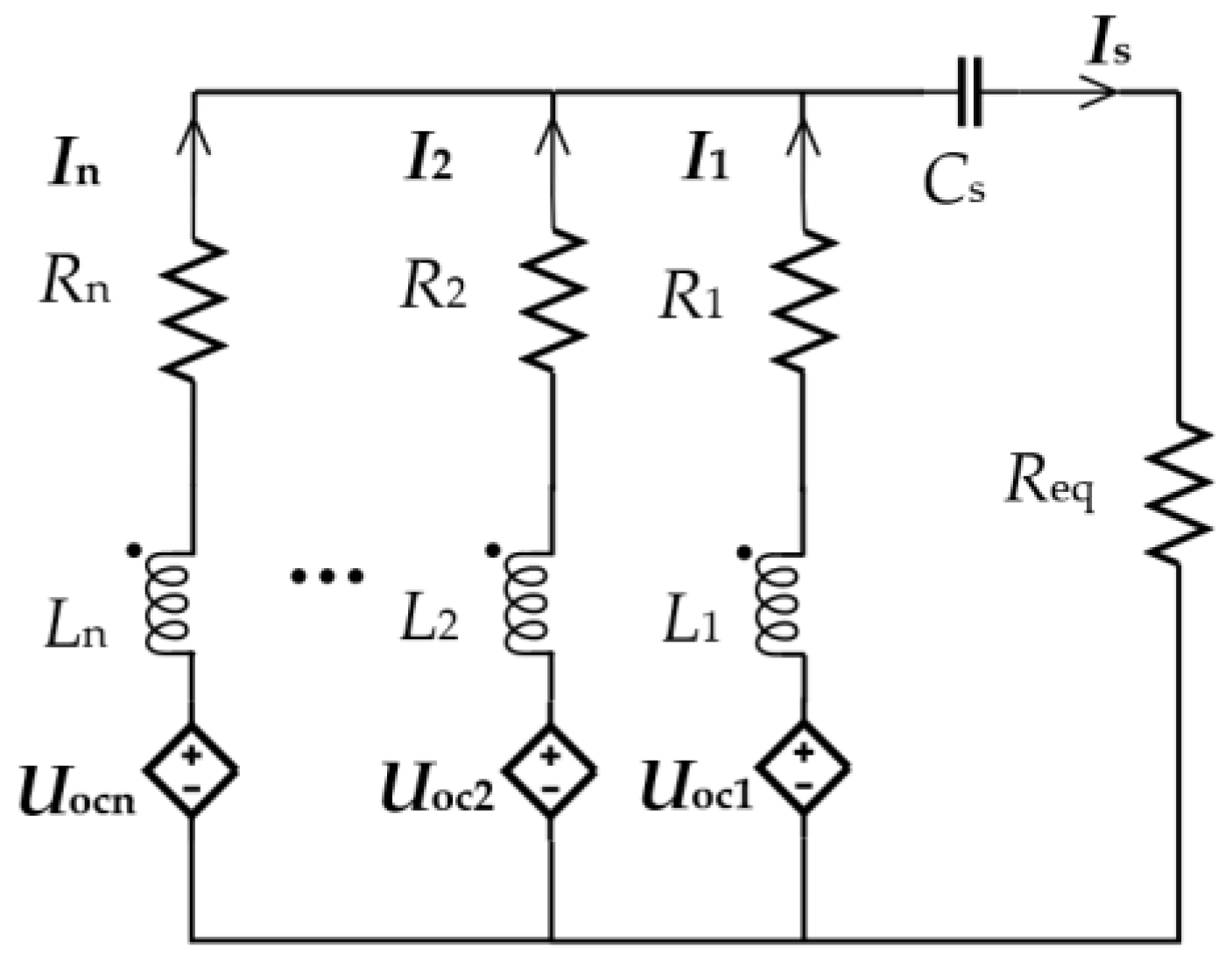
3.1. Analysis of n Branches Parallel to One Capacitor

With n branches being connected in parallel, the schematic diagram of the coil is shown in Figure 3. Lp and Cp are the self-inductance and compensation capacitance of the transmitting coil, respectively. Ii (I = 1, 2, …, n) is the current of the receiving coil i. Li is the self-inductance of the receiving coil i, and Cs is the compensation capacitor of the whole receiving coil. Mpi is the mutual inductance between the transmitting coil and receiving coil i, and Mij (j = 1, 2, …, n) is the mutual inductance between the receiving coils. The coil diagram above is equivalent to the equivalent circuit diagram with a controlled source, as shown in Figure 4. Uoci is the induced voltage of the original side coil on the secondary side coil i. Ri is the AC resistance of each branch.
The calculation process of a capacitor compensation circuit is too complicated. The calculation form cannot accurately express the unequal current of each branch, so the unequal current state is expressed by simulation later.

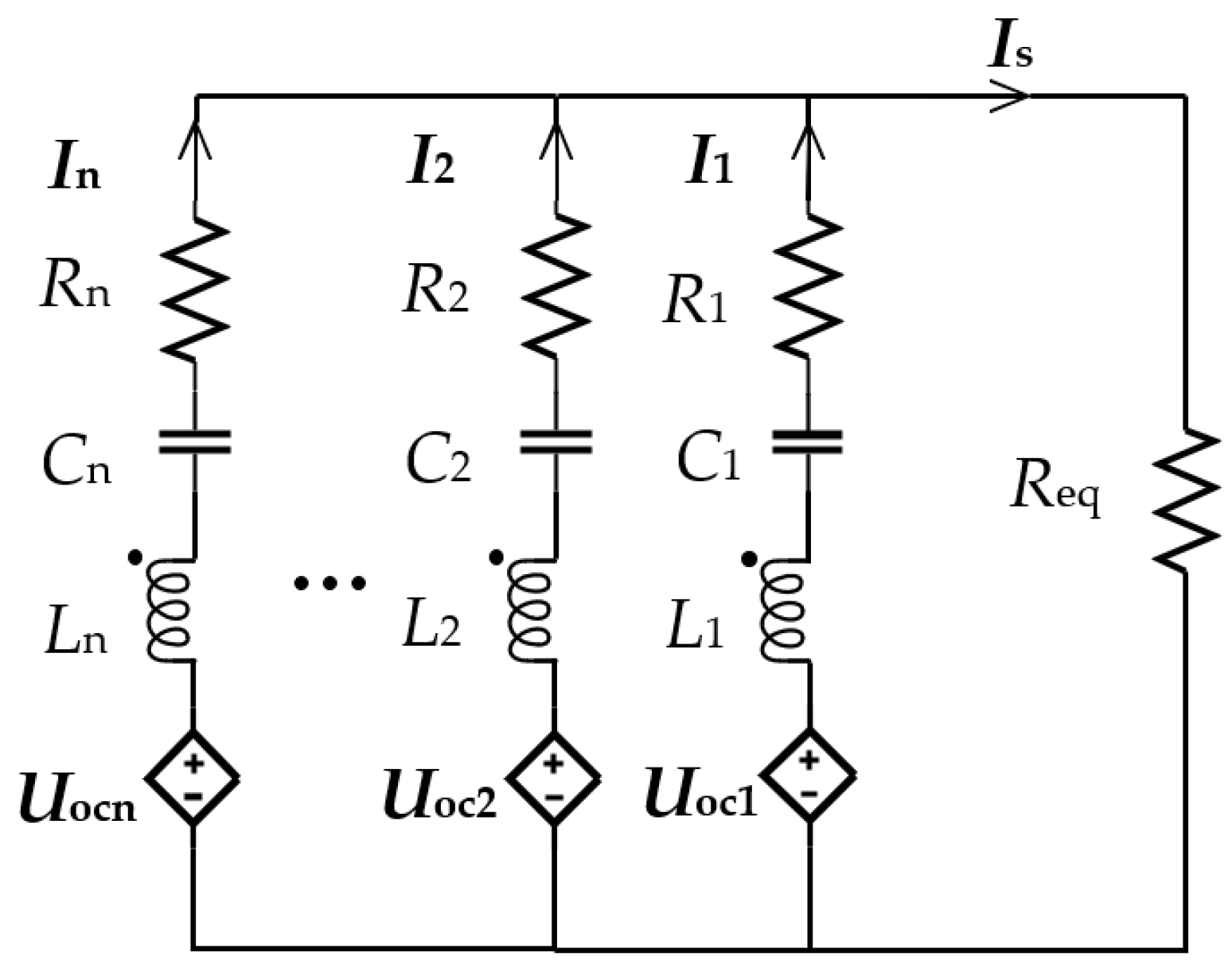
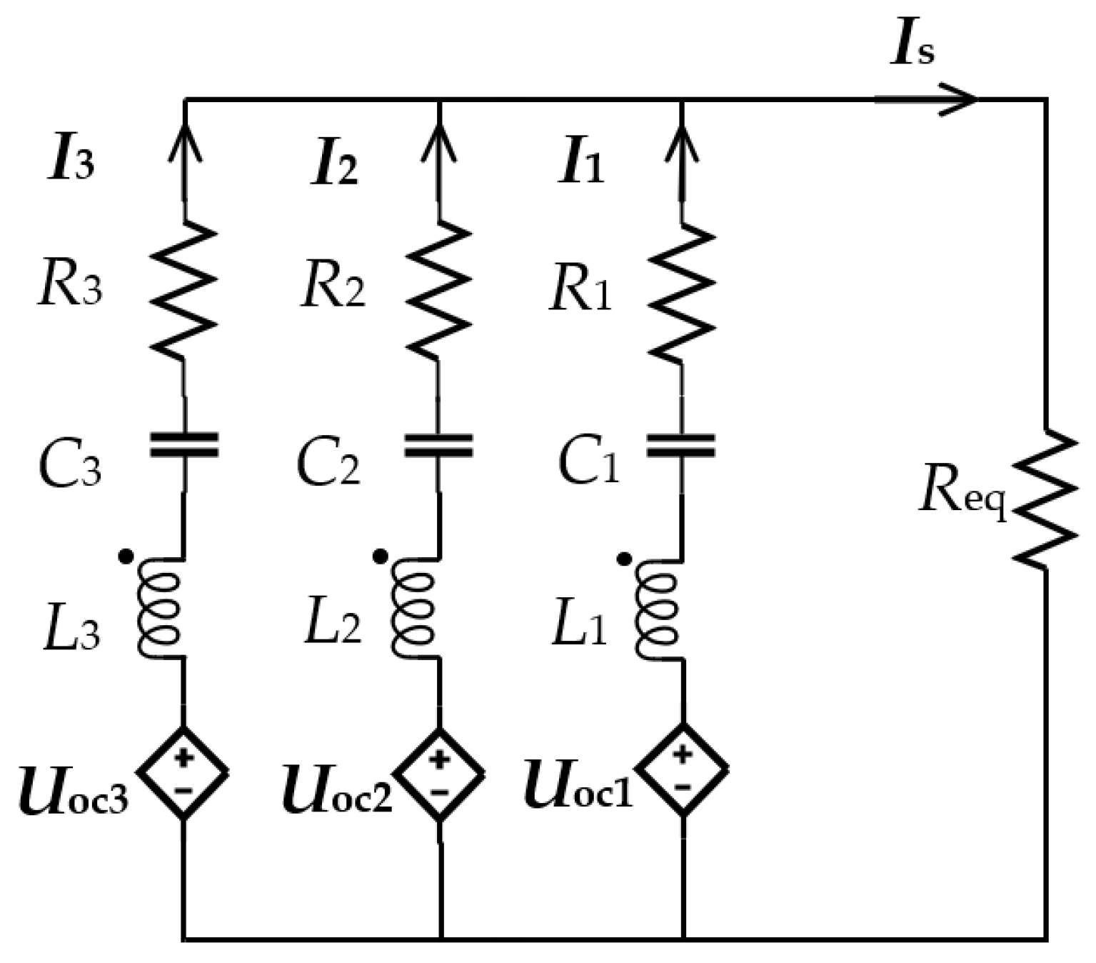
3.2. Analysis of n Branches Parallel to Three Capacitors

With n branches being compensated with n capacitors, the diagram is shown in Figure 5. Li and Ci are, respectively, the self-inductance and compensation capacitance of the receiving coil i. Other parameters are described above. The equivalent circuit diagram is shown in Figure 6.
According to Figure 6 and Kirchhoff’s laws, Equation (9) is obtained as follows:
U o c 1 + j ω L 1 I 1 + j ω M 12 I 2 + j ω M 13 I 3 + + j ω M 1 n I n j 1 ω C 1 I 1 + I 1 R 1 = R eq ( I 1 + I 2 + + I n ) U o c 2 + j ω L 2 I 2 + j ω M 21 I 1 + j ω M 23 I 3 + + j ω M 2 n I n j 1 ω C 2 I 2 + I 2 R 2 = R eq ( I 1 + I 2 + + I n ) U o c n + j ω L n I n + j ω M n 1 I 1 + j ω M n 2 I 2 + + j ω M n ( n 1 ) I n 1 j 1 ω C n I n + I n R n = R eq ( I 1 + I 2 + + I n ) .
Complete resonance compensation is adopted, and the capacitance is calculated according to the following:
ω L 1 + ω M 12 + + ω M 1 n = 1 ω C 1 ω L 2 + ω M 21 + + ω M 2 n = 1 ω C 2 ω L n + ω M n 1 + + ω M n ( n 1 ) = 1 ω C n .
By substituting Equation (10) into Equation (9) and letting k11 = I1/I1, k12 = I2/I1, k13 = I3/I1, …, k1n = In/I1, Equation (11) can be obtained:
U oc 1 + j ω M 12 ( k 12 1 ) I 1 + + j ω M 1 n ( k 1 n 1 ) I 1 + I 1 R 1 = R eq ( I 1 + I 2 + + I n ) U oc 2 + j ω M 21 ( 1 k 12 ) I 1 + + j ω M 1 n ( k 1 n k 12 ) I 1 + I 2 R 2 = R eq ( I 1 + I 2 + + I n ) U ocn + j ω M n 1 ( 1 k 1 n ) I 1 + + j ω M n ( n 1 ) ( k 1 ( n 1 ) k 1 n ) I 1 + I n R n = R eq ( I 1 + I 2 + + I n ) .
The matrix form of Equation (11) can be expressed as follows:
U oc 1 U oci U ocn + j ω I 1 M k 11 k 1 i k 1 n + I 1 A = R eq ( I 1 + + I n ) 1 1 1 ,
where
A = k 11 R 1 k 12 R 2 k 1 n R n T ,
M = ( 1 ) ( M 12 + + M 1 n ) M 1 i M 1 n M i 1 ( 1 ) ( M i 1 + + M in ) M in M n 1 M ni ( 1 ) ( M n 1 + + M n ( n 1 ) )
The n formulas on the left side of Equation (11) are equal. I0 is allowed to be the effective value of the average current of n branches, namely that of I0 = (I1 + I2 + … + In)/n. When I1 is greater than I0, with I2, I3, …, and In being smaller than I0, the k12, k13, …, and k1n decrease. As a result, the left side of the first equation of Equation (11) becomes lower, and the left side of other equations becomes higher. Afterward, subject to the constraints of the equation, I1 needs to be reduced, and the currents of the other circuits need to be increased, thereby maintaining the current sharing state.

3.3. Analysis of Efficiency

The calculation equation, constraint condition, and extreme value of coil loss are as follows:
P Loss = i = 1 n R i I i 2 ,
f ( I i ) = i = 1 n I i I s = 0 ,
P ( I i , λ ) = P Loss + λ f ( I i ) .
In Equation (17), λ is a derivable parameter in the extreme value formula, and the extreme point of power can be obtained from Equation (18).
P 1 = 2 R 1 I 1 + λ = 0 P 2 = 2 R 2 I 2 + λ = 0 P n = 2 R n I n + λ = 0 P λ = i = 1 n I i I 2 = 0
The unique extreme value point can be obtained, and the formula for calculating the n current values of the extreme value point is shown in Equation (19).
I i * = 1 R i j = 1 n 1 R j I s ,   i , j = 1 , 2 , n .
The expression of the current value of the extreme point is similar to the expression of the resistance form of the parallel shunt with n paths. By comparing the special value of the boundary and the magnitude of the extreme value, it can be determined that the extreme value is the minimum value. For a coil wound with n parallel wires, the AC resistance of the n wires is basically equal, so the current value of the extreme value point is basically equal to the current value of the average current, thus achieving higher efficiency.
In the high-frequency Litz wire coil of a wireless power transmission system, the AC resistance [12] includes a conductive resistance (Rcond) and an induced resistance (Rind), as shown in Equation (20).
R ac = R cond + R ind
The conductive resistance consists of the DC resistance and the equivalent resistance of the skin effect. For the system determined by frequency, its size is only related to wire parameters such as wire thickness and length [13]. The induced resistance is the equivalent resistance of the proximity effect, which is related to the magnetic induction intensity of the adjacent wire to this wire [28]; therefore, its size is not only affected by the parameters of the wire itself but is also related to the distance of the adjacent conductor. The higher the number of turns of the wire is or the closer the distance between the wires is, the stronger the magnetic field and the higher the resistance are.
For the coils in which two wires are connected in parallel, what affects the resistance is the conductive resistance because the induced resistance is the same, so there should be no gap between the two wires (the turn spacing between different turns of the same wire cannot be affected by this); therefore, the AC resistance of the two wires is basically the same. In the case that three or four wires are in parallel, the conductive resistance of the outer wire is higher, and the induced resistance of the middle wire is higher too. If the distance between the wires is zero, the influence of the induced resistance may be higher than that of the conductive resistance. Therefore, the distance between the parallel wires should be appropriately increased to reduce the induced resistance so that the resistance of the other wires except the innermost wire may be as close to the same as possible. If the number of parallel wires is more than four, the conductive resistance and inductive resistance of each wire can be basically equal according to transposition.

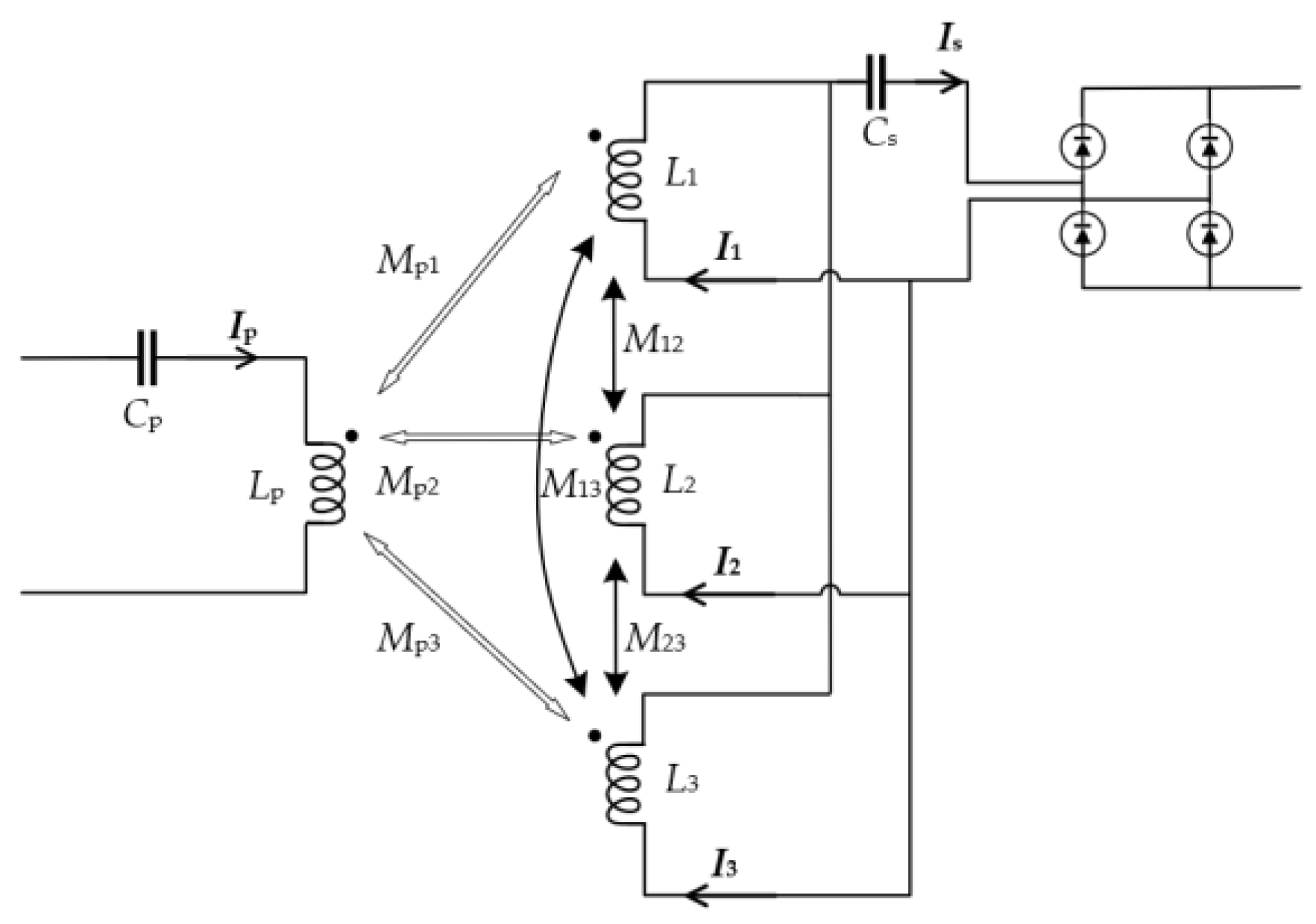
3.4. Analysis of Three Parallel Branches

Taking the three-coil example, the three capacitors are separated, and the resonant compensation is adopted, as shown in Figure 7. The coil schematic diagram above is equivalent to the circuit of the sub-sideband-controlled source, as shown in Figure 6, and the parameters are the same as those in Section 3.1.
Through Figure 8 and Kirchhoff’s laws, the equation is as follows:
U oc 1 + j ω L 1 I 1 + j ω M 12 I 2 + j ω M 13 I 3 j 1 ω C 1 I 1 + I 1 R 1 = R eq ( I 1 + I 2 + I 3 ) U oc 2 + j ω L 2 I 2 + j ω M 21 I 1 + j ω M 23 I 3 j 1 ω C 2 I 2 + I 2 R 2 = R eq ( I 1 + I 2 + I 3 ) U oc 3 + j ω L 3 I 3 + j ω M 31 I 1 + j ω M 32 I 2 j 1 ω C 3 I 3 + I 3 R 3 = R eq ( I 1 + I 2 + I 3 ) .
The formula for calculating the capacitance value is as follows:
ω L 1 + ω M 12 + ω M 13 = 1 ω C 1 ω L 2 + ω M 21 + ω M 23 = 1 ω C 2 ω L 3 + ω M 31 + ω M 32 = 1 ω C 3 .
With k12 = I2/I1, k13 = I3/I1 being permitted, Equation (22) is substituted into Equation (21) to obtain the following:
U oc 1 + j ω M 12 ( k 12 1 ) I 1 + j ω M 13 ( k 13 1 ) I 1 + I 1 R 1 = R eq ( I 1 + I 2 + I 3 ) U oc 2 + j ω M 21 ( 1 k 12 ) I 1 + j ω M 23 ( k 13 k 12 ) I 1 + I 2 R 2 = R eq ( I 1 + I 2 + I 3 ) U oc 3 + j ω M 31 ( 1 k 13 ) I 1 + j ω M 32 ( k 12 k 13 ) I 1 + I 3 R 3 = R eq ( I 1 + I 2 + I 3 ) .
Then, there is the following:
A = V oc 1 + I 1 R 1 + j ω M 12 ( k 12 1 ) I 1 + j ω M 13 ( k 13 1 ) I 1 , B = V oc 2 + I 2 R 2 + j ω M 21 ( 1 k 12 ) I 1 + j ω M 23 ( k 13 k 12 ) I 1 , C = V oc 2 + I 3 R 3 + j ω M 31 ( 1 k 13 ) I 1 + j ω M 32 ( k 12 k 13 ) I 1 ,
and then A = B = C. When I1 is higher than the average I0 and the other circuit currents are less than I0, k12 decreases and k13 decreases. Afterward, A decreases, B increases, and C increases. Being subject to equality constraints, I1 decreases, and other currents increase and maintain the current sharing state.

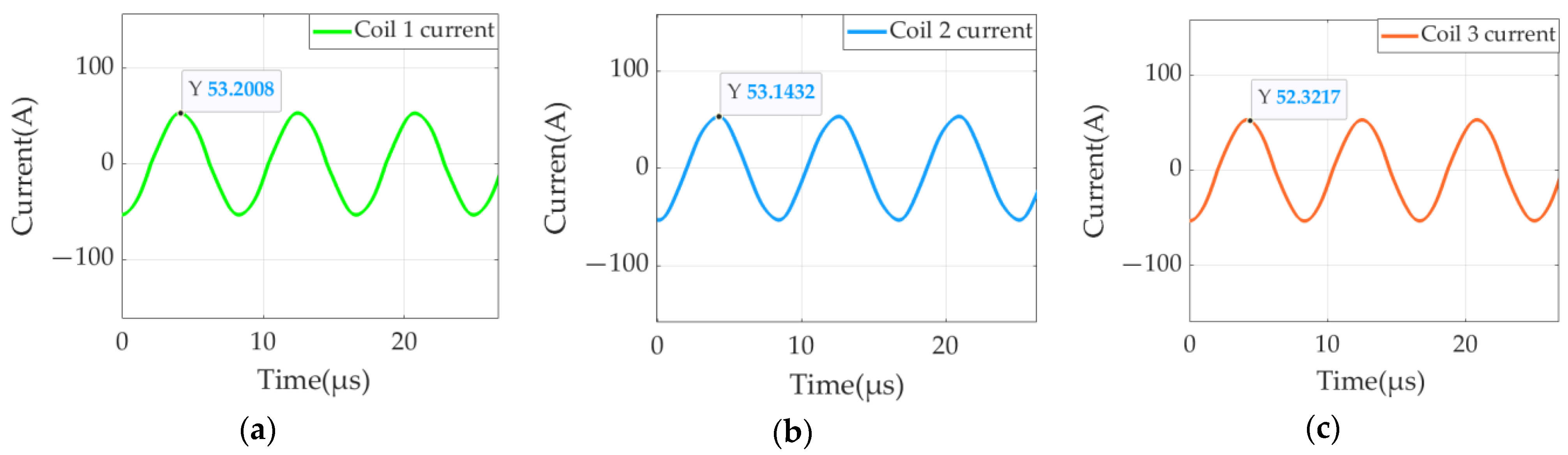
4. Simulation Verification of Parallel Current Sharing

The theoretical part of current sharing is derived above, and the simulation verification is carried out in this section. The simulation tools use Maxwell and Simulink, and the coupling mechanism is simulated in Maxwell to obtain the coil self-inductance and mutual inductance. Then, they are substituted into the Simulink simulation module to simulate the current sharing effect, and finally the Icepack simulation is used to compare the coil temperatures of the current sharing and uneven current sharing. The 100 A system is taken as an example. At the same power, increasing the primary voltage level can reduce the current level of the primary coil, thus reducing the loss of the primary coil and improving the efficiency. In addition, considering the voltage withstand level of the inverter, the primary DC voltage is 500 V. According to Equation (6), increasing the system frequency can improve the efficiency, but a higher system frequency will also lead to higher coil AC resistance loss and magnetic core loss. A single strand of thinner Litz wire is needed to reduce AC resistance. Considering the cost, a system frequency of 120 k and a Litz wire with a single-strand diameter of 0.05 mm are selected. According to the characteristics of the SS structure, the 100 A current at the load end is equivalent to 112 A in the AC circuit before rectification [26]. In order to leave a certain margin, the effective value is 120 A. The coupling coefficient can be selected as 0.2. From the previous analysis, in order to ensure the stability of the system, the quality factor of the secondary coil should not be too high. After selecting the inductance of the secondary coil, the primary inductance can be calculated using Equation (4), and the compensation capacitance can be calculated according to the resonance of the capacitance and inductance. The selected system parameters are shown in Table 1. The Maxwell simulation model includes coils, magnetic cores, and aluminum plates, and the three coils are coplanar and centered, as shown in Figure 9a. The magnetic core used in Figure 9a is a strip core, the schematic diagram is shown in Figure 9b, the core parameters are calculated in reference [29], and the strip core parameters are shown in Table 2. The core material is PC95, and the thickness of the magnetic core is 5 mm [30]. The aluminum plate is close to the magnetic core. The schematic diagram of the receiving coil is shown in Figure 9c. The coil winding adopts the winding method whereby the pitch of coil is equal to the wire diameter [31].
In Figure 9c, the turns are numbered 1–9 from the inside to the outside. The first, fourth, and seventh turns are the first wires, which are connected in series and wound into coil 1. Similarly, the second, fifth, and eight ones are the second wires, which are wound into coil 2. The third, sixth, and ninth ones are the third wires, which are wound into coil 3. Then, the three coils are connected in parallel to form the receiving coil.
The mutual inductance between the transmitting coil and each coil on the receiving side and its resistance can be obtained by simulating the above model, as shown in Table 3. The self-inductance of each coil on the receiving side and the mutual inductance between them are shown in Table 4.
After the inductance value is obtained by MAXWELL and the capacitance value is then obtained by calculation, the current values of different wires can be obtained by Simulink. When using single capacitor compensation, the secondary side compensation capacitor Cs is 349 nF. When using three capacitors for compensation, the value of the three capacitors on the secondary side can be calculated through Table 4 and Equation (22). The calculation result is C1 = 120 nF, C2 = 114 nF, and C3 = 115 nF. The Simulink model is built according to Figure 6, and the simulated self-inductance, mutual inductance, and corresponding capacitance values are brought into the model. Figure 10 shows the currents when one capacitor is compensated, and Figure 11 shows the currents when three capacitors are compensated.
In Figure 10, the effective values of the current of receiving coil 1, the current of receiving coil 2, and the current of receiving coil 3 are 52 A, 27 A, and 32 A, respectively. According to the previous Simulink simulation, this is caused by the different mutual inductance of the primary and secondary coils and the cross-coupling of the secondary coils. The abscissas of the three current waveforms in Figure 11 have the same time. The peak currents of the three coils are 54 A, 53 A, and 53 A (effective value: 37 A), respectively. Therefore, the currents of the three coils have the same frequency and phase, and their magnitudes are basically equal. By comparison, the use of multi-capacitor compensation can effectively avoid the problem of the uneven distribution of the multi-coil current and prevent the coil from being damaged by an excessive coil current.

5. Analysis of the Effect of Current Sharing Optimization

5.1. Efficiency Comparison of Three Branches in Parallel

The current effective values of the three wires corresponding to the minimum loss are shown in Table 5, which are obtained from Equation (19) and Table 3. The current values are not much different from the current sharing current effective value of 37 A. In addition, it is found in the simulation that when the core shape and the turn spacing of the coil change, the coil’s current distribution without current sharing measures highly changes. Efficiency cannot be accurately estimated; therefore, the measure of current sharing is closest to the extreme point of efficiency.

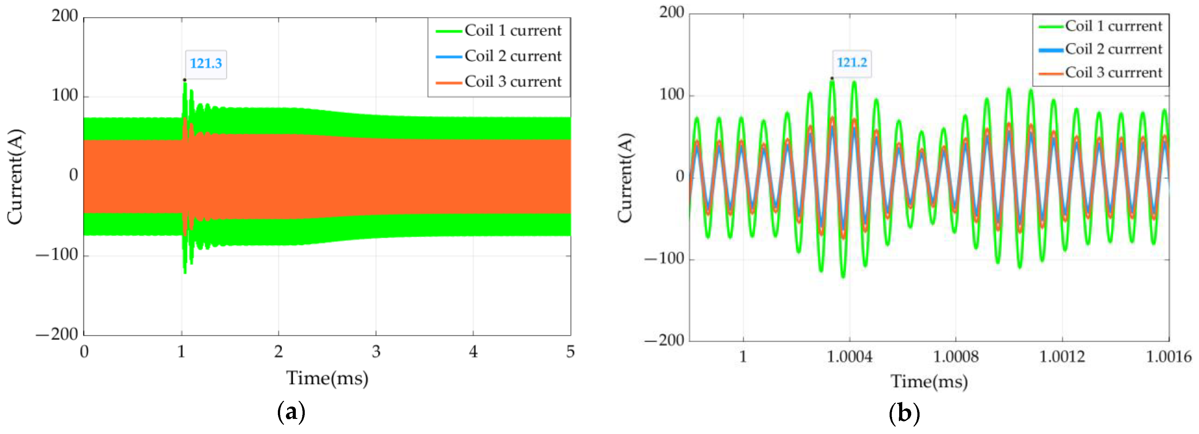
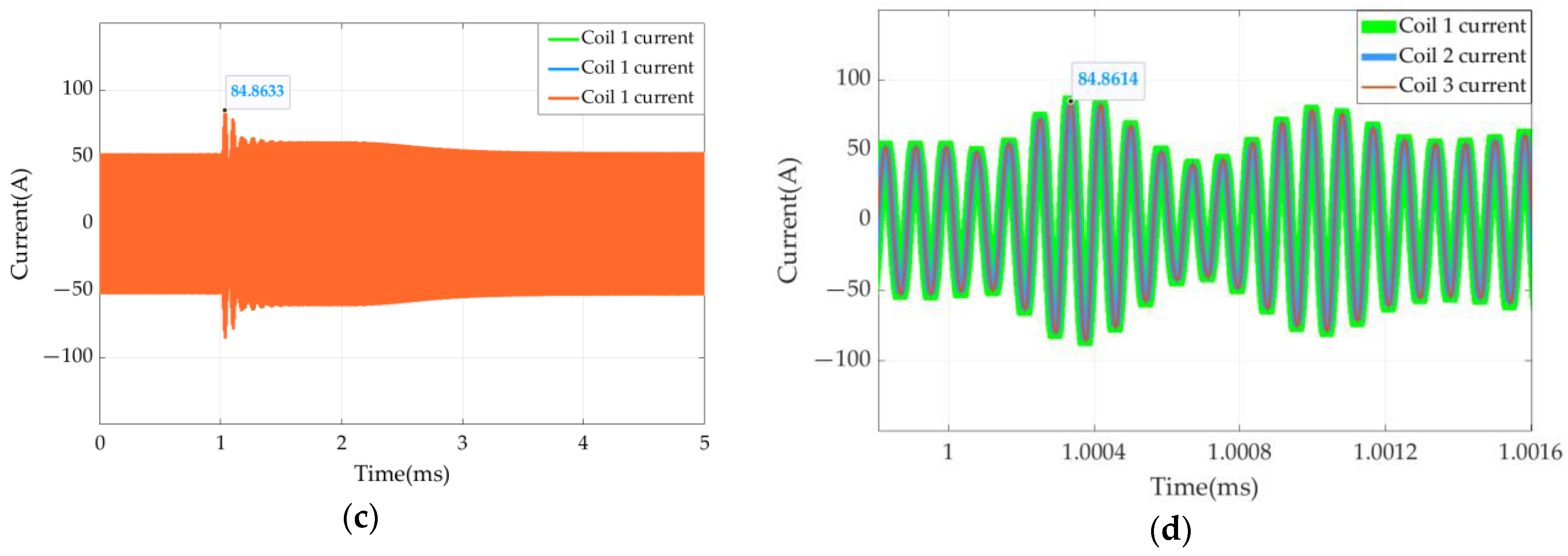
5.2. System Disturbance Analysis

A sudden load disturbance is applied to the system after the stable operation of the system, and the optimization effect of the current sharing measure is further analyzed by observing the fluctuation of the current value and the time that it takes for the system to restore stability. Figure 12 shows the current diagram of the three wires of the receiving coil whose load changes from 0.48 Ω to 0.78 Ω. The disturbance occurs at 1 ms.
As can be seen from Figure 12, after adopting the current sharing measure, the coil current can still maintain the current sharing state when the load is disturbed. The maximum current fluctuation and rise range of the two schemes are shown in Table 6. The proportion of the current increase of the coil with the current sharing measure is smaller than that of the coil without the current sharing measure, so the current sharing measure can improve the anti-disturbance performance of the system. In addition, the current amplitude of the coil without current sharing measures increases too much when it is disturbed, which will threaten the safety of the coil. In order to avoid wire damage due to current fluctuation, thicker wires need to be used. This will undoubtedly increase the cost.

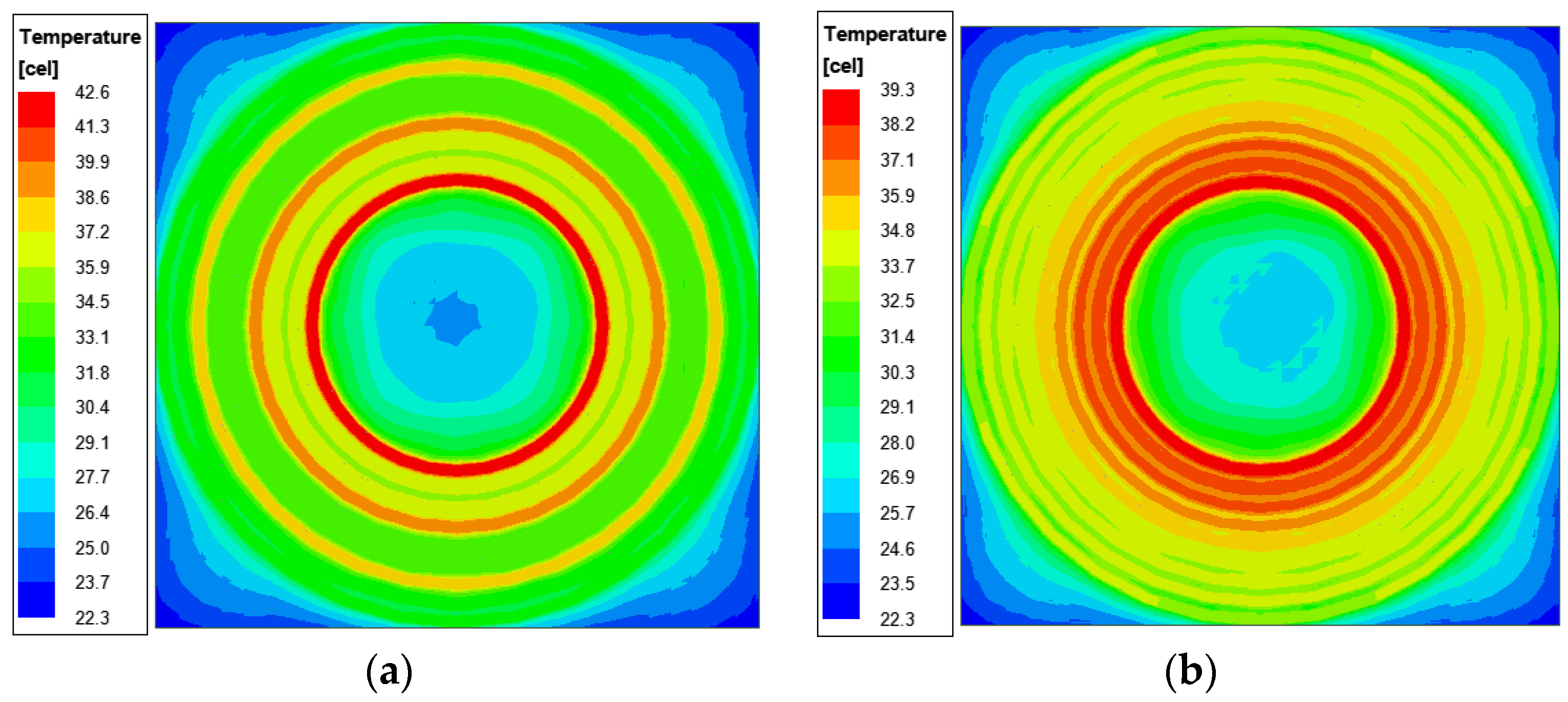
5.3. Temperature Simulation Comparison

When multiple coils are connected in parallel, the current of each coil is different. The coil that flows through the high current will also generate more heat, and the coil will be damaged when the local temperature of the coil is too high. Therefore, the thermal simulation of the coupling mechanism is carried out in the cases of current sharing and non-current sharing, and the temperature changes of the receiving coil under the two conditions are compared and analyzed. The temperature simulation results are shown in Figure 12. The unit used in the picture is Celsius, and the initial ambient temperature is 20 °C. The temperature rise between the two is compared.
It can be seen from Figure 13a that the temperature on the innermost side is the highest, with a temperature rise of 23 °C. This is because the innermost coil has the highest current. In Figure 13b, the coil’s maximum temperature rise is 19 °C, with a reduction of 4 °C and a reduction of 17%, because the current of the innermost coil is reduced due to the current sharing measure. After comparing the temperature simulation cloud images of the two cases, the temperature of the secondary coil with the current sharing measure is lower, the temperature is more uniform from the inside to the outside, and there are basically no local hot spots in the middle of the coil.

6. Experimental Verification

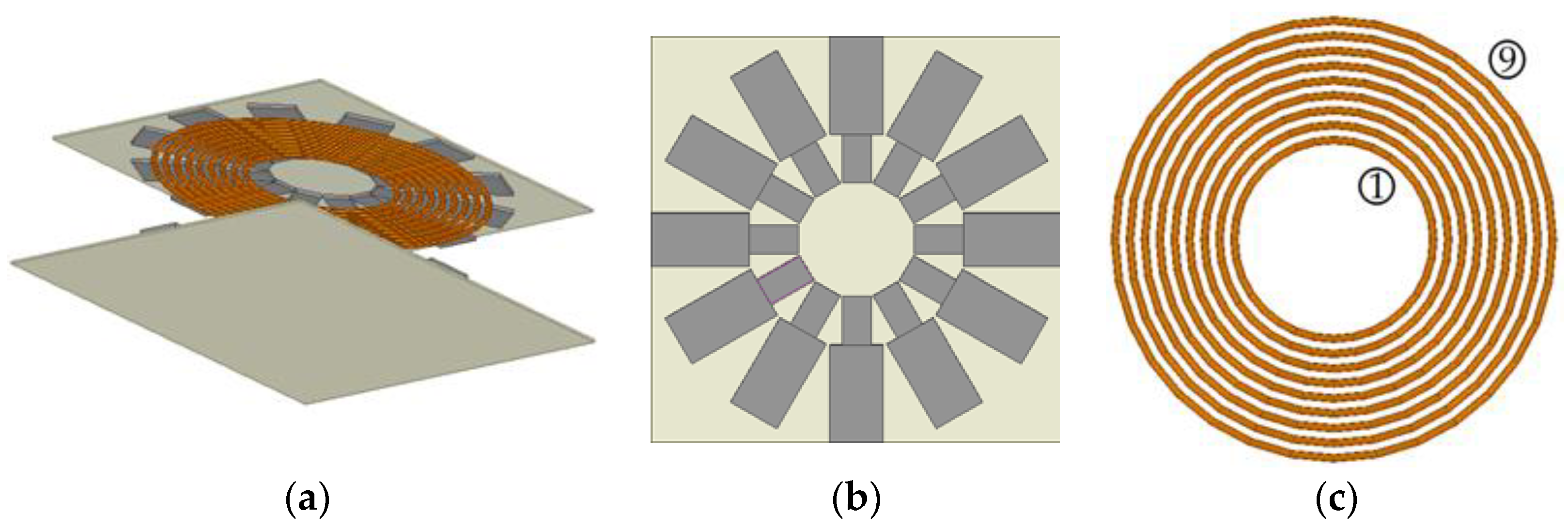
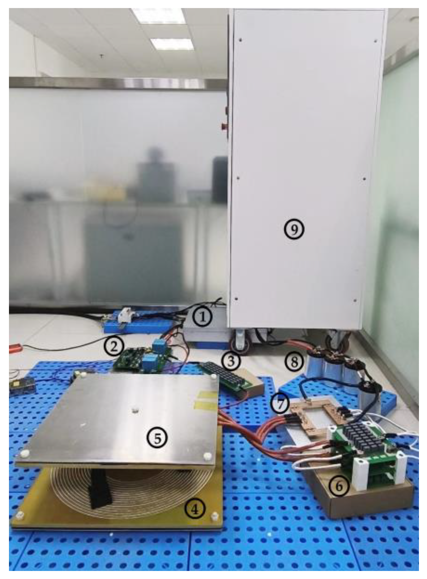
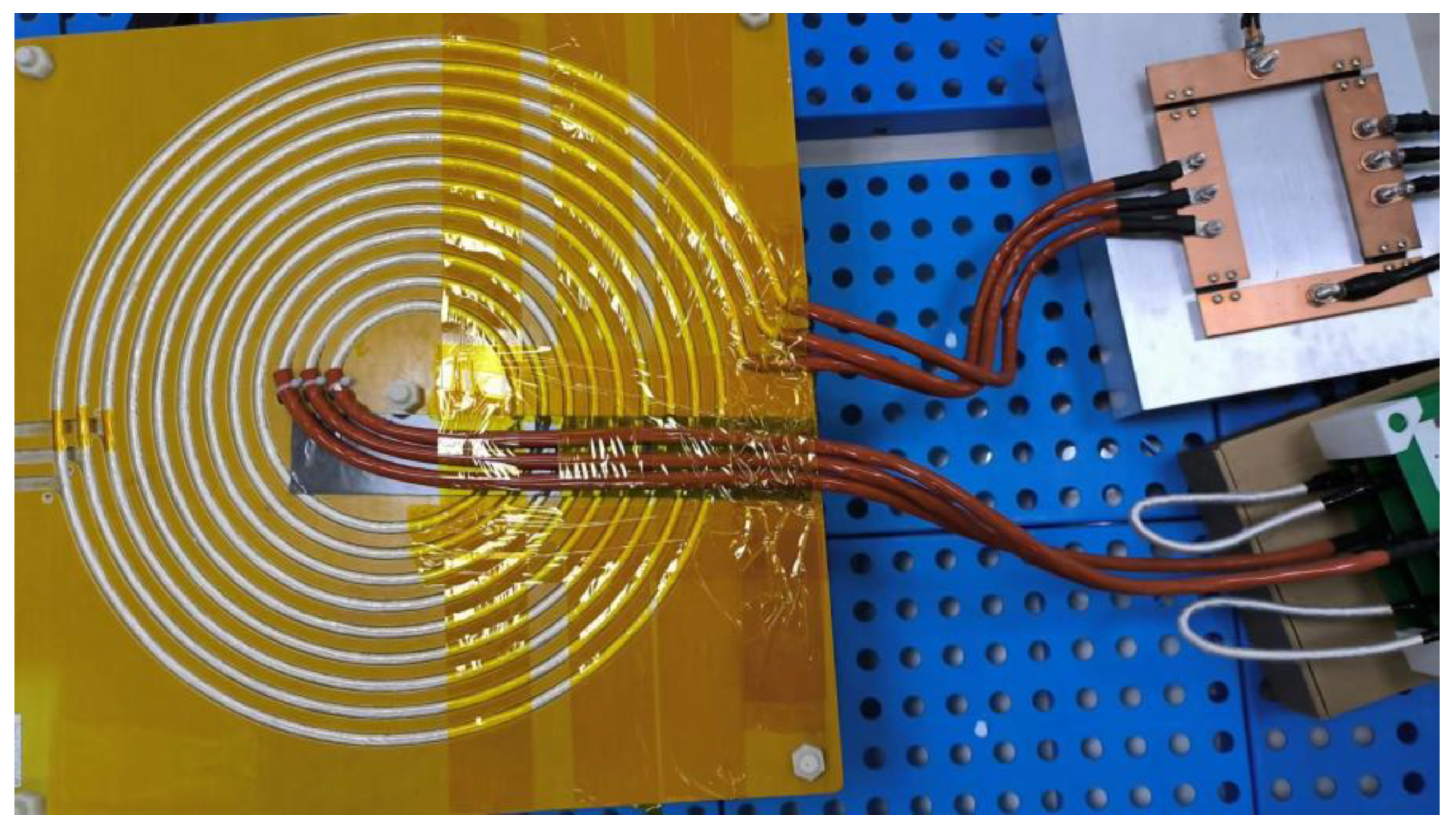
6.1. Experimental Prototype

The experimental equipment of the wireless power transfer system is shown in Figure 14. The inverter is composed of type IMZ120R045M1 MOSFET, and the rectifier bridge is composed of four modules of VS-UFB280FA20. The type of filter capacitor is D3B2K527K202722, and the load is 0.48 Ω. The parameters of the core and aluminum plate are shown in Table 1 and Table 2. The coil is fixed in a 1 cm thick epoxy sheet, and the magnetic core is glued to the other side of the epoxy sheet. This paper focuses on the current sharing of the secondary side coil, and the schematic diagram of the secondary side coupling mechanism is shown in Figure 15. The measured values of the inductance and mutual inductance of the primary and secondary side coils are shown in Table 7. The resonant capacitance, which is calculated according to Table 7 and Equation (22), is shown in Table 8.

6.2. Experimental Results

The capacitance of Table 8 is separately connected through the current sharing connection, and its parallel connection is that of the resonant compensation capacitance of the whole secondary coil, which is the non-current sharing connection. In these two cases, the oscilloscope is used to measure the current of the three wires, and the results are compared. Because the inner wire is larger in the case of a non-uniform current, the main purpose of this experiment is to verify the effect of current sharing measures. Therefore, for the safety of the experiment, the primary DC input voltage is set at 100 V.
It can be seen from Figure 16a that when the current sharing measure is not taken, the current of the three wires is 12 A, 6.38 A, 4.24 A, respectively, and 12 A is the innermost current. The current of the three wires widely varies from the obvious phase difference, and the current of the innermost wire is nearly three times higher than that of the minimum current. Therefore, the pressure of the innermost wire is the highest, and there is bound to be a more serious heating phenomenon. Because of the experimental equipment that was used in this paper, it is not convenient to use a thermal imager to measure the coil temperature, so the coil temperature measurement is not carried out here. However, through the existing analysis, it can be concluded that the temperature of the inner wire is higher when the flow is uneven.
In Figure 16b, the current of the three wires is 7.38 A, 7.32 A, 7.06 A, respectively. The phase difference of the three currents is very low, the effective values of the current are basically the same, and the error between the maximum and minimum values as well as the average value are less than 3%. Therefore, compared with the situation of the uneven flow, the pressure of the inner wire is lower, the temperature is also lower, and the system is safer.
The comparison between the two shows that the current sharing measures proposed in this paper have an obvious effect on balancing the current of each wire. And it is also necessary to take current sharing measures after the current level is increased.

7. Conclusions

In this paper, a current sharing method of multi-branch and multi-capacitor compensation is proposed to solve the problem of the non-uniform current of multiple coils on the receiving side of a high-current wireless charging system, which leads to a poor anti-disturbance ability and a high local temperature. The calculation formulas of the compensation capacitance of each branch are derived and compared by simulation, and the following conclusions are obtained:
(1) The difference in the mutual inductance between the primary and secondary coils and the cross-coupling between the receiving coils leads to the non-uniform current of the secondary coils. By adding capacitors to each coil, the resonant compensation for the self-inductance of the coil, and the mutual inductance of the secondary multiple coils, the influence of an uneven current that is caused by different mutual inductance and cross-coupling can be eliminated.
(2) The current of the innermost coil is the highest, and its value is more than twice that of the coil with the smallest current, so the danger of an overload in the innermost coil is high when the load is disturbed. When the current sharing measure of multi-coil and multi-capacitor compensation is adopted, the current of each coil is basically equal, and the current of the innermost wire is obviously reduced.
(3) When the current is uneven, because the innermost coil has the highest current, the temperature of the innermost coil is as high as 23 °C. After the current equalization measure is adopted, the current of the coil is significantly reduced, and its temperature is also reduced by 4 °C, which is a drop of up to 17%, thereby preventing the coil from overheating and effectively improving the safety of the system.
Finally, the effectiveness of the current sharing measure is verified through experiments, which provides a solution for the system design with a higher current level.

Author Contributions

Conceptualization, Y.X.; methodology, S.C.; software, S.C. and Y.Z.; validation, Y.X. and X.L.; formal analysis, Y.X. and G.Q.; investigation, Y.X., Z.L. and G.Q.; resources, Y.X. and Y.Z.; data curation, S.C. and G.Q.; writing—original draft preparation, Y.X.; writing—review and editing, G.L., Z.L. and Y.Z.; visualization, Y.X.; supervision, G.L. and X.L.; project administration, G.L. and X.L.; funding acquisition, Z.L. All authors have read and agreed to the published version of the manuscript.

Funding

This research was funded by the Natural Science Foundation of Shandong Province, grant number ZR2021ME009.

Data Availability Statement

Data are contained within the article.

Acknowledgments

This paper would like to express special thanks to Zhizhen Liu for his guidance on the writing and the funding of the experimental equipment. Many thanks go to Yuandi Zhao for his help in the experiment process.

Conflicts of Interest

The authors declare no conflicts of interest. Yuandi Zhao is an employee of Jinan EMag Electric Co., Ltd. The paper reflects the views of the scientists and not the company.

References

  1. Kim, J.H.; Lee, B.; Lee, J.; Lee, S.; Park, C.; Jung, S.; Lee, S.; Yi, K.; Baek, J. Development of 1-MW Inductive Power Transfer System for a High-Speed Train. IEEE Trans. Ind. Electron. 2015, 62, 6242–6250. [Google Scholar] [CrossRef]
  2. Covic, G.A.; Boys, J.T. Modern Trends in Inductive Power Transfer for Transportation Applications. IEEE J. Emerg. Sel. Top. Power Electron. 2013, 1, 28–41. [Google Scholar] [CrossRef]
  3. Elliott, G.A.J.; Covic, G.A.; Kacprzak, D.; Boys, J.T. A New Concept: Asymmetrical Pick-Ups for Inductively Coupled Power Transfer Monorail Systems. IEEE Trans. Magn. 2006, 42, 3389–3391. [Google Scholar] [CrossRef]
  4. Luo, B.; Long, T.; Guo, L.; Dai, R.; Mai, R.; He, Z. Analysis and Design of Inductive and Capacitive Hybrid Wireless Power Transfer System for Railway Application. IEEE Trans. Ind. Appl. 2020, 56, 3034–3042. [Google Scholar] [CrossRef]
  5. Shin, J.; Shin, S.; Kim, Y.; Ahn, S.; Lee, S.; Jung, G.; Jeon, S.; Cho, D. Design and Implementation of Shaped Magnetic-Resonance-Based Wireless Power Transfer System for Roadway-Powered Moving Electric Vehicles. IEEE Trans. Ind. Electron. 2014, 61, 1179–1192. [Google Scholar] [CrossRef]
  6. Li, W.; Zhao, H.; Li, S.; Deng, J.; Kan, T.; Mi, C.C. Integrated LCC Compensation Topology for Wireless Charger in Electric and Plug-in Electric Vehicles. IEEE Trans. Ind. Electron. 2015, 62, 4215–4225. [Google Scholar] [CrossRef]
  7. Kumar, K.; Chowdary, V.V.S.R.; Mali, V.; Kumar, R. Analysis of Output Power Variation in Dynamic Wireless Charging System for Electric Vehicles. In Proceedings of the 2021 IEEE 2nd International Conference on Smart Technologies for Power, Energy and Control (STPEC), Bilaspur, India, 19–22 December 2021; pp. 1–6. [Google Scholar]
  8. Kavitha, M.; Bobba, P.B.; Prasad, D. Comprehensive mathematical modelling and experimental analysis of a wireless power transfer system for neighborhood electric vehicles. In Proceedings of the 2015 IEEE International WIE Conference on Electrical and Computer Engineering (WIECON-ECE), Dhaka, Bangladesh, 19–20 December 2015; pp. 275–279. [Google Scholar]
  9. Liu, F.; Zhang, Y.; Chen, K.; Zhao, Z.; Yuan, L. A comparative study of load characteristics of resonance types in wireless transmission systems. In Proceedings of the 2016 Asia-Pacific International Symposium on Electromagnetic Compatibility (APEMC), Shenzhen, China, 17–21 May 2016; pp. 203–206. [Google Scholar]
  10. Zaheer, A.; Kacprzak, D.; Covic, G.A. A bipolar receiver pad in a lumped IPT system for electric vehicle charging applications. In Proceedings of the 2012 IEEE Energy Conversion Congress and Exposition (ECCE), Raleigh, NC, USA, 15–20 September 2012; pp. 283–290. [Google Scholar]
  11. Takanashi, H.; Sato, Y.; Kaneko, Y.; Abe, S.; Yasuda, T. A large air gap 3 kW wireless power transfer system for electric vehicles. In Proceedings of the 2012 IEEE Energy Conversion Congress and Exposition (ECCE), Raleigh, NC, USA, 15–20 September 2012; pp. 269–274. [Google Scholar]
  12. Deng, Q.; Liu, J.; Czarkowski, D.; Kazimierczuk, M.K.; Bojarski, M.; Zhou, H.; Hu, W. Frequency-Dependent Resistance of Litz-Wire Square Solenoid Coils and Quality Factor Optimization for Wireless Power Transfer. IEEE Trans. Ind. Electron. 2016, 63, 2825–2837. [Google Scholar] [CrossRef]
  13. Acero, J.; Hernandez, P.J.; Burdio, J.M.; Alonso, R.; Barragdan, L.A. Simple resistance calculation in litz-wire planar windings for induction cooking appliances. IEEE Trans. Magn. 2005, 41, 1280–1288. [Google Scholar] [CrossRef]
  14. Li, H.; Wang, K.; Huang, L.; Li, J.; Yang, X. Coil structure optimization method for improving coupling coefficient of wireless power transfer. In Proceedings of the 2015 IEEE Applied Power Electronics Conference and Exposition (APEC), Charlotte, NC, USA, 15–19 March 2015; pp. 2518–2521. [Google Scholar]
  15. Lu, M.; Ngo, K.D.T. Systematic Design of Coils in Series–Series Inductive Power Transfer for Power Transferability and Efficiency. IEEE Trans. Power Electron. 2018, 33, 3333–3345. [Google Scholar] [CrossRef]
  16. Cheng, Y.; Shu, Y. A New Analytical Calculation of the Mutual Inductance of the Coaxial Spiral Rectangular Coils. IEEE Trans. Magn. 2014, 50, 7026806. [Google Scholar] [CrossRef]
  17. Sun, Y.; Xia, C.; Dai, X.; Su, Y. Analysis and optimization of mutual inductance for inductively coupled power transfer system. Proc. CSEE 2010, 30, 44–50. [Google Scholar]
  18. Bosshard, R.; Kolar, J.W.; Wunsch, B. Accurate finite-element modeling and experimental verification of inductive power transfer coil design. In Proceedings of the 2014 IEEE Applied Power Electronics Conference and Exposition—APEC 2014, Fort Worth, TX, USA, 16–20 March 2014; pp. 1648–1653. [Google Scholar]
  19. Wang, C.S.; Stielau, O.H.; Covic, G.A. Design Considerations for a Contactless Electric Vehicle Battery Charger. IEEE Trans. Ind. Electron. 2005, 52, 1308–1314. [Google Scholar] [CrossRef]
  20. Kurs, A.; Moffatt, R.; Soljačić, M. Simultaneous mid-range power transfer to multiple devices. Appl. Phys. Lett. 2010, 96, 044102. [Google Scholar] [CrossRef]
  21. Ahn, D.; Hong, S. Effect of Coupling Between Multiple Transmitters or Multiple Receivers on Wireless Power Transfer. IEEE Trans. Ind. Electron. 2013, 60, 2602–2613. [Google Scholar] [CrossRef]
  22. Shen, H.; Liu, X.; Yan, C.; Chen, X. Analysis and Optimization of High-Power MCR Bidirectional WPT System with High Distance-Diameter Ratio. In Proceedings of the IECON 2021—47th Annual Conference of the IEEE Industrial Electronics Society, Toronto, ON, Canada, 13–16 October 2021; pp. 1–6. [Google Scholar]
  23. Niu, S.; Yu, H.; Niu, S.; Jian, L. Power loss analysis and thermal assessment on wireless electric vehicle charging technology: The over-temperature risk of ground assembly needs attention. Appl. Energy 2020, 275, 115344. [Google Scholar] [CrossRef]
  24. Hwang, K.; Chung, S.; Yoon, U.; Lee, M.; Ahn, S. Thermal analysis for temperature robust wireless power transfer systems. In Proceedings of the 2013 IEEE Wireless Power Transfer (WPT), Perugia, Italy, 15–16 May 2013; pp. 52–55. [Google Scholar]
  25. Zhu, C.; Fu, C.; Wang, D.; Huang, X.; Zhang, H.; Dong, S.; Wei, G.; Song, K. Thermal Simulation and Optimization Study for Magnetic Coupler of Static Electric Vehicle Wireless Power Transfer Systems. In Proceedings of the 2019 22nd International Conference on Electrical Machines and Systems (ICEMS), Harbin, China, 11–14 August 2019; pp. 1–4. [Google Scholar]
  26. Duerbaum, T. First harmonic approximation including design constraints. In Proceedings of the INTELEC—Twentieth International Telecommunications Energy Conference (Cat. No.98CH36263), San Francisco, CA, USA, 4–8 October 1998; pp. 321–328. [Google Scholar]
  27. Feng, A.; Mao, Z.; Qin, H. Bifurcation Phenomena and Phase Shift Control Strategy in Loosely Coupled Inductive Power Transfer System. J. Shanghai Dianji Univ. 2010, 13, 17–21. [Google Scholar]
  28. Bagchi, A.C.; Kamineni, A.; Zane, R. Analytical Optimization of a Litz Wire Spiral Coil Based Underwater IPT System. In Proceedings of the 2018 IEEE Energy Conversion Congress and Exposition (ECCE), Portland, OR, USA, 23–27 September 2018; pp. 2456–2463. [Google Scholar]
  29. Xie, Y.; Liu, Z.; Hou, Y.; Luo, X.; Sun, S.; Ding, R. Optimal Design of Magnetic Cores for the Circular Coil in Wireless Power Transfer System. In Proceedings of the 2023 International Conference on Power System Technology (PowerCon), Jinan, China, 21–22 September 2023; pp. 1–5. [Google Scholar]
  30. Shijo, T.; Ogawa, K.; Obayashi, S. Optimization of thickness and shape of core block in resonator for 7 kW-class wireless power transfer system for PHEV/EV charging. In Proceedings of the 2015 IEEE Energy Conversion Congress and Exposition (ECCE), Montreal, QC, Canada, 20–24 September 2015; pp. 3099–3102. [Google Scholar]
  31. Sampath, J.P.K.; Alphones, A.; Shimasaki, H. Coil design Guidelines for High Efficiency of Wireless Power Transfer (WPT). In Proceedings of the 2016 IEEE Region 10 Conference (Tencon), Singapore, 22–25 November 2016; pp. 726–729. [Google Scholar]
Figure 1. Structure of a SS-type wireless power transfer system.
Wevj 15 00058 g001
Figure 2. Equivalent circuit diagram.
Wevj 15 00058 g002
Figure 3. Schematic diagram of n branches parallel to one capacitor.
Wevj 15 00058 g003
Figure 4. Equivalent circuit.
Wevj 15 00058 g004
Figure 5. Schematic diagram of n branches parallel to three capacitors.
Wevj 15 00058 g005
Figure 6. Equivalent circuit with n capacitors.
Wevj 15 00058 g006
Figure 7. Schematic diagram of the separate resonance compensation.
Wevj 15 00058 g007
Figure 8. Equivalent circuit diagram of three branches in parallel.
Wevj 15 00058 g008
Figure 9. Schematic diagram of the coupling mechanism. (a) Primary and secondary coupling mechanisms. (b) Schematic diagram of the coupling mechanism. (c) Diagram of the three coils in parallel.
Wevj 15 00058 g009
Figure 10. Receiving coil current with one capacitor compensation.
Wevj 15 00058 g010
Figure 11. Receiving coil current with three capacitors compensation: (a) coil 1 current; (b) coil 2 current; (c) coil 3 current.
Wevj 15 00058 g011
Figure 12. Disturbance simulation results: (a) receiving coil current without the current sharing measure; (b) detailed waveform at disturbance without the current sharing measure; (c) receiving coil current with the current sharing measure; (d) detailed waveform at disturbance with the current sharing measure.
Wevj 15 00058 g012aWevj 15 00058 g012b
Figure 13. Temperature simulation results: (a) coil temperature without the measure of current sharing; (b) coil temperature with the measure of current sharing.
Wevj 15 00058 g013
Figure 14. Experimental equipment: ① DC power supply; ② inverter equipment; ③ Cp; ④ primary side coupling mechanism; ⑤ secondary side coupling mechanism; ⑥ C1,C2,C3; ⑦ rectifier bridge; ⑧ filter capacitor; ⑨ electronic load.
Wevj 15 00058 g014
Figure 15. Schematic diagram of the secondary side coil.
Wevj 15 00058 g015
Figure 16. Receiving coil current: (a) current distribution without the current sharing measure; (b) current distribution with the current sharing measure.
Wevj 15 00058 g016
Table 1. The 5 kW wireless charging system parameters.
ParametersValuesParametersValues
primary AC equivalent voltage (V)500primary Litz wire0.05 × 3000
side length of primary
/secondary aluminum plate (cm)
54/50secondary Litz wire0.05 × 10,000
total inductance of receiving coil (μH)5primary
/secondary pitch (mm)
4.5/7.5
Lp (μH)152k0.2
Cp (nF)11.57load voltage (V)48
frequency (kHz)120load current (A)100
Cs (nF)352RL (Ω)0.48
distance between the primary coil and the magnetic core (mm)5.5distance between the secondary coil and the magnetic core(mm)2.5
Table 2. Strip core parameters.
ParametersValues
primary sidefirst ringradius (mm)80–150
length/width (mm)70/40
second ringradius (mm)150–270
length/width (mm)120/70
secondary sidefirst ringradius (mm)70–130
length/width (mm)60/35
second ringradius (mm)130–250
length/width (mm)120/65
Table 3. Primary and secondary coil mutual inductance and resistance.
ParametersValuesParametersValues
Mp1 (μH)6.6Rp (mΩ)83.9
Mp2 (μH)6.9R1 (mΩ)8.6
Mp3 (μH)7.0R2 (mΩ)9.9
R3 (mΩ)10.8
Table 4. Receiving coil self-inductance and mutual inductance.
ParametersValuesParametersValues
L1 (μH)5.6M12 (μH)4.6
L2 (μH)6.0M13 (μH)4.4
L3 (μH)6.1M23 (μH)4.8
Table 5. Receiving coil self-inductance and mutual inductance.
ParametersValues
I1 (A)41
I2 (A)36
I3 (A)34
Table 6. Maximum current fluctuation and rise range of the two schemes.
ParametersWithout Current Sharing MeasureWith Current Sharing Measure
Maximum current fluctuation(A)121.384.86
Rise range65%62%
Table 7. Experimental receiving coil’s self-inductance and mutual inductance.
ParametersValuesParametersValues
L1 (μH)5.67M12 (μH)4.27
L2 (μH)6.69M13 (μH)4.32
L3 (μH)7.48M23 (μH)5.02
Table 8. Receiving coil’s self-inductance and mutual inductance.
ParametersValues
C1 (μF)123
C2 (μF)110
C3 (μF)105
Disclaimer/Publisher’s Note: The statements, opinions and data contained in all publications are solely those of the individual author(s) and contributor(s) and not of MDPI and/or the editor(s). MDPI and/or the editor(s) disclaim responsibility for any injury to people or property resulting from any ideas, methods, instructions or products referred to in the content.

