Abstract
The accurate identification of a driver’s braking intention is crucial to the formulation of regenerative braking control strategies for electric vehicles. In this paper, a braking intention recognition model based on the sample entropy of the braking signal and a probabilistic neural network (PNN) is proposed to achieve the accurate recognition of different braking intentions. Firstly, the brake pedal travel signal is decomposed to extract the effective components via variational modal decomposition (VMD); then, the features of the decomposed signal are extracted using sample entropy to obtain the multidimensional feature vector of the braking signal; finally, the sparrow search algorithm (SSA) and probabilistic neural network are combined to optimize the smoothing factor with the sparrow search algorithm and the cross-entropy loss function as the fitness function to establish a braking intention recognition model. The experimental validation results show that combining the sample entropy features of the braking signal with the probabilistic neural network can effectively identify the braking intention, and the SSA-PNN algorithm has higher recognition accuracy compared with the traditional machine learning algorithm.
1. Introduction
The range of electric vehicles is an important factor limiting their development. In the absence of a key breakthrough in battery energy storage technology, regenerative braking technology can help improve the range, and braking intention recognition is closely related to regenerative braking technology, which has attracted much attention in the automotive industry. By using the results of brake intent recognition, the regenerative braking control strategy can be adjusted to reasonably allocate regenerative braking force and mechanical braking force to improve the efficiency of braking energy recovery and achieve the increased range of electric vehicles [1]. Accurately recognizing braking intent has a direct impact on regenerative energy recovery efficiency, so it is important to identify braking intent quickly and accurately.
Braking intention cannot be directly measured due to the subjective influence of the driver and can only be identified by extracting features from the variation of parameters. Researchers have studied different perspectives, such as the selection of braking parameters and braking intention algorithms. For the selection of braking parameters, Zhu and Li established a braking intention recognition model by analyzing the mechanism of driver cortical activity based on a driving simulator and functional near-infrared spectroscopy experiments [2]. Li and Wang used the driver’s electroencephalogram (EEG) as the data input and obtained the energy features after wavelet transformation for intention recognition [3]. In addition to the driver’s EEG information, driver operation and vehicle state data obtained through experiments are often used as state parameters. For example, Zheng [4] used pedal displacement, displacement change rate, brake chamber pressure, wheel speed, and its deviation rate to form the feature samples and selected them for multi-condition intent. Research on braking intention recognition algorithms can be divided into three main categories: threshold setting, fuzzy inference, and machine learning. Intent recognition by setting thresholds mainly appeared in the early stages of research, but the recognition rate of this method is low. Fuzzy inference, which has the characteristics of good adaptability, a simple algorithm, and a nonlinear advantage, is widely applied in the field of intention recognition. For example, Liu and Zhang identified the relationship between brake pedal displacement, braking intent, and braking intensity by designing a brake pedal fuzzy logic controller [5]. An adaptive network fuzzy inference system was investigated in the literature [6] to defuzzify the braking intention parameters and build a braking intention recognition model. With the development of machine learning, supervised and unsupervised machine learning algorithms are also applied in the field of brake intention recognition. Lei and Zhang [7] used the Gustafson–Kessel cluster analysis algorithm for brake intention recognition. In order to improve the recognition accuracy, more accurate features are applied in the clustering algorithm. For example, Wang combined the features in the frequency domain of the braking signals with the clustering algorithm to recognize the braking intention [8]. Neural networks have also been applied in the field of brake intention recognition due to their high recognition accuracy. Based on the temporal sequence of braking behaviors, studies in the literature [9] have adopted long- and short-term memory neural networks to construct a model to achieve the recognition of braking intention, while Xing [10] considered the hierarchical and sequential features of hidden Markov models from the connection between driving intentions and driving behaviors and constructed a two-layer Markov model with behavioral and intention layers to achieve the recognition of long and complex driving intentions. In addition, the recognition model combining intelligent optimization algorithms and machine learning algorithms is also very helpful for the recognition of braking intentions. Li designed a driver intention recognition method based on the artificial bee colony optimization support vector machine and compared it with the BP neural network, the particle swarm optimization vector machine, and other algorithms with good results [11]. Compared with a single recognition model, the application of a two-layer recognition model also improves the recognition rate of braking intention. Studies in the literature [12,13,14] used a two-layer intention recognition model that combined a Markov model with a support vector machine and a neural network to complete the recognition of braking intention.
In summary, the research on braking intention recognition focuses on the feature extraction of braking signals. Mining the hidden features of the braking signal is the focus of the research, and at present, the recognition of braking intention mainly selects the brake pedal position information, position change rate, speed change rate, and other time domain information as the recognition features and combines them with machine learning algorithms to carry out the research. This paper proposes a braking intention recognition model based on the sample entropy feature of the braking signal, which consists of two parts: one part is to analyze the braking signal in the time–frequency domain and extract the sample entropy as the signal feature, and the other part is to use a probabilistic neural network to identify the braking intention. In order to improve the recognition accuracy, we use the sparrow searching algorithm to search for the optimal parameters, and finally, we prove the feasibility and accuracy of this recognition method through comparative validation. Finally, the feasibility and accuracy of the recognition method are proved through comparative verification.
The structure of this paper is arranged as follows: First, the braking intention recognition model based on the sample entropy of the braking signal is constructed, and then, the dSPACE-based braking signal acquisition platform is built to acquire the voltage signal of the brake pedal. Finally, the validation analysis is carried out based on the acquired braking signals, comparing and verifying the validity of the sample entropy and the accuracy of the SSA-PNN algorithm.
2. Sample Entropy Extraction for Braking Signals
Accurately extracting the features of the braking signal first requires the performance of the variational modal decomposition of the acquired braking signal, the decomposition of the braking signal into multiple IMF signals, the extraction of the effective components in the original signal, and then the extraction of the sample entropy features for the decomposed IMF signals.
2.1. Brake Signal Processing
Due to the complexity and nonsmoothness of the braking signal, it is difficult to extract the signal features accurately by directly finding the sample entropy for them. Therefore, in this paper, variational modal decomposition (VMD) is used to process the braking signal [15], and the effective components of the original signal are obtained by decomposing the original signal into an intrinsic modal function (IMF), in preparation for the subsequent extraction of the sample entropy as signal features.
Variational Modal Decomposition is a decomposition estimation method for signals, using which, the frequency center and bandwidth of the decomposed components can be obtained by iteratively searching for the optimal solution of the variational model to achieve the adaptive separation of signals under the premise of preserving the effective components. The VMD can self-determine the number of modal decompositions to reduce the complexity of high nonlinearity and strong time series smoothness.
The schematic diagram of the VMD is shown in Figure 1. The VMD assumes that all the components are concentrated in the signal around its center frequency and uses this to build a constrained optimization problem to estimate the center frequency and the corresponding components of the signal components [16].

Figure 1.
VMD schematic.
The essence of variational modal decomposition is to solve the variationally constrained problem shown in Equation (1) [17]:
In Formula (1), f(t) is the target signal; uk and ωk are the decomposed signal of f(t) and its center frequency, respectively; and K denotes the total number of uk.
The key to solving the problem shown in Equation (1) lies in the introduction of the Lagrange operator λ(t), which can be used to obtain the optimal solution of the problem by pretending to be an unconstrained problem [18].
The VMD decomposition is completed by alternating directional multipliers to achieve alternating updates to uk and ωk.
In Formulas (3) and (4), n is the number of iterations. , , , and represent, respectively, the Fourier transform of , , , and .
Iteration is carried out according to Equations (3) and (4) until Equation (5) is satisfied [19], at which point, the iteration ends.
In Formula (5), is the convergence accuracy; the size is generally 10−6.
Through the abovementioned process, the braking signal is decomposed into multiple IMF signals for the sample entropy extraction of the braking signal after variational modal decomposition. Based on the opening of the brake pedal and its rate of change, brake signals are categorized into three types: a deceleration brake, parking brake, and emergency brake. Figure 2 shows the output signal of the brake pedal and its variational modal decomposition results.
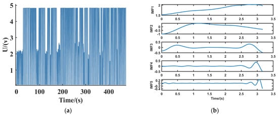
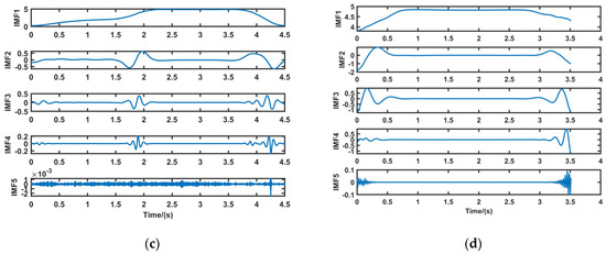
Figure 2.
Brake pedal output signal and decomposition results. (a) brake pedal output signals; (b) deceleration brake signal; (c) parking brake signal; (d) emergency brake signal.
2.2. Sample Entropy Extraction
In this paper, the brake pedal position information is selected as the recognition parameter, the signal processing is carried out via variational modal decomposition, and the sample entropy is extracted from the decomposed signal as the input of the recognition model. The process of solving the sample entropy is shown in Equations (6)–(12) under [20]:
- (1)
- Construct a sequence of vectors of dimension m, . where, .
- (2)
- Take the absolute value of the maximum difference between the corresponding elements of and as the distance between the two vectors.
- (3)
- Define as the number of () for which the distance between and is less than or equal to r. When , it can be expressed as:
- (4)
- Define as:
- (5)
- Increase the dimension to m + 1 and count the number of and () whose distances are less than or equal to r. Denote the definition of as: Define as the number of with distances less than or equal to r from ( in m + 1 dimensions
- (6)
- Define as:
Thus, is the probability of two sequences matching m points at a similar tolerance r, while is the probability of two sequences matching m + 1 points. The sample entropy is defined as:
When N is a finite number, Equation (11) can be transformed into Equation (12) to estimate the sample entropy:
A group of acquired braking signals can be extracted via the VMD decomposition of the effective components to obtain five groups of IMF component signals that are not in the center frequency, and then, the sample entropy for each group of IMF signals can be solved to complete the feature extraction of a group of braking signals. Figure 3 shows the sample entropy of the IMF components of the three braking intention signals.
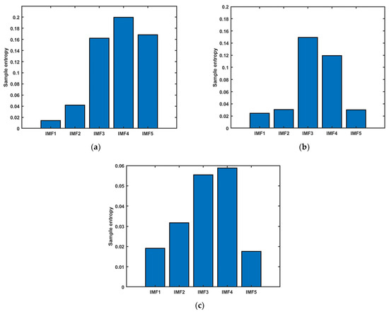
Figure 3.
Sample entropy of the IMF component of the braking signals.(a) deceleration brake signal sample entropy; (b) parking brake signal sample entropy; (c) emergency braking signal sample entropy.
3. SSA-PNN Brake Intention Recognition Algorithm
The braking intention recognition model constructed in this paper is mainly divided into two parts: the recognition algorithm and the optimization algorithm. The probabilistic neural network is chosen as the recognition algorithm, and the sparrow search algorithm is used as the optimization algorithm to improve the recognition accuracy of the probabilistic neural network.
3.1. PNN Brake Intention Recognition Model
Probabilistic neural networks are a type of radial basis function neural network and belong to the forward propagation category [21].
Probabilistic neural networks have the advantages of fast computation time, good robustness, and simple and instant training compared to other radial basis function neural networks. PNNs are well suited for real-time processing, have good scalability, and are easy to implement in hardware with their relatively fixed neurons. Therefore, probabilistic neural networks are widely used in pattern recognition, nonlinear mapping, classification, and other fields [22,23,24].
The PNN recognition model consists of an input layer, a pattern layer, a summation layer, and an output layer, and the structure is shown in Figure 4.
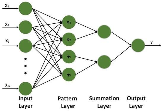
Figure 4.
Probabilistic neural network structure.
The input layer of the model is responsible for passing feature vectors into the network with the same number of neurons as the sample dimensions. The pattern layer is the middle link between the input layer and the summation layer, using the Gaussian function as the activation function, calculating the similarity between the input feature vectors and each pattern in the training set, and feeding its distance into the Gaussian function to obtain the output of the pattern layer. The similarity is calculated as shown in Equation (13).
In Formula (13), is the weight between the input layer and the summation layer; is the smoothing factor, the value of which will directly affect the merit of the neural network.
The summation layer sums up the probabilities of patterns attributed to the same type and calculates a probability density function for each class with the same number of neurons as the number of recognition target types. The output layer is responsible for outputting the recognition results.
In the PNN model constructed in this paper, the input layer contains five neurons consistent with the number of sample features; the number of neurons in the pattern layer is determined by the input layer; the number of neurons in the summation layer is three, which is the same as the number of identification types; and the number of neurons in the output layer is one. In a PNN based on density function kernel estimation, one hidden layer neuron is determined for each training sample, and the neurons’ weights are directly taken from the input sample values. There is no need to optimize the neuron weights through reverse iteration, which greatly reduces the computational complexity and allows for easy training and fast convergence.
3.2. PNN Smoothing Factor Optimization
After the structure of the SSA-PNN algorithm has been determined, it needs to be trained as well as tested. The recognition accuracy of the PNN is only affected by the smoothing factor, which greatly reduces the complexity of the optimization of the neural network. To ensure the goodness of neural network training, the optimal smoothing factor needs to be determined. In this paper, the cross-entropy loss function is used to evaluate the network’s merit and determine the optimal smoothing factor. The cross-entropy is used as the fitness function of the SSA algorithm, and the smoothing factor of the neural network is output through the search iteration of the SSA algorithm when the optimal fitness is achieved, so as to ensure the goodness of the network.
The sparrow search algorithm (SSA) consists of a discoverer, joiner, and detector [25]. Among them, the position update formula of the discoverer is shown in Equation (14) [26]:
In Formula (14), and , represent the warning value and safety value, respectively; the size of the value of the two indicates whether the region is safe or not, and when the region is safe, the sparrow flock will carry out a large-scale search, and vice versa, it will be quickly withdrawn. t and T denote the number of the current iteration and the maximum number of iterations, respectively, and denotes the location information value of the i-th sparrow in the j-th dimension iteration times for t, and is the random number of .
The formula for updating joiner positions is shown in Equation (15) [26].
In Formula (15), is the global worst fitness of the finder in the population during the tth search for excellence, is the location of the best fitness in the t + 1st search for excellence, and A denotes a column vector of the same dimensions as an individual sparrow and satisfies .
The formula for updating the position of the scout is shown in Equation (16) [26].
In Formula (16), is the current global optimum position; is the step control parameter; is a random number, and is the current fitness value of the individual sparrow. and are the current global best and worst fitness values, respectively. When , the sparrow is at the edge of the population and has been attacked, and when , the sparrow in the middle of the population is aware of the danger and therefore needs to move closer to other sparrows to reduce the probability of predation.
3.3. SSA-PNN Braking Intent Recognition Process
The probabilistic neural network recognition model and recognition process using the sparrow search algorithm to find the best values are shown in Figure 5.
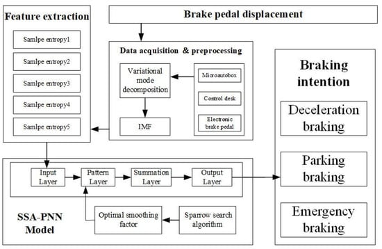
Figure 5.
SSA-PNN algorithm recognition flow chart.
4. Experimental Analysis
The experimental analysis is divided into two parts—data acquisition and validation analysis—and the constructed recognition model is validated by the data collected by the platform. Comparative analyses are conducted to identify the effectiveness of the features and recognition models.
4.1. Data Acquisition
This paper divides braking intentions into three categories: deceleration braking, parking braking, and emergency braking [27]. Deceleration braking indicates braking for the purpose of slowing down and usually occurs on speed-limited roads. Stopping braking is braking for the purpose of stopping and often occurs at red lights or junctions. Emergency braking is the act of stopping a vehicle in an emergency situation. The brake signal acquisition platform built on the basis of the dSPACE semi-physical simulator is shown in Figure 6, which enables the acquisition of brake signals with different braking intentions in real life. The platform consists of an electronic brake pedal, a dSPACE MicroAutoBox, a host PC, and a DC-regulated power supply. Micautobox is a semi-physical simulator produced by dSPCE, Germany, which allows the study of rapid control prototypes and hardware-in-the-loop simulation. The DC-regulated power supply provides 24 V and 12 V to the MicroAutoBox and the electronic brake pedal, respectively. The electronic brake pedal is the braking signal emitting a voltage signal of 0–4.85 V to characterize the brake pedal travel as the braking action is applied. dSPACE MicroAutoBox is responsible for the real-time transfer of the braking signal to the host PC for data storage and analysis.
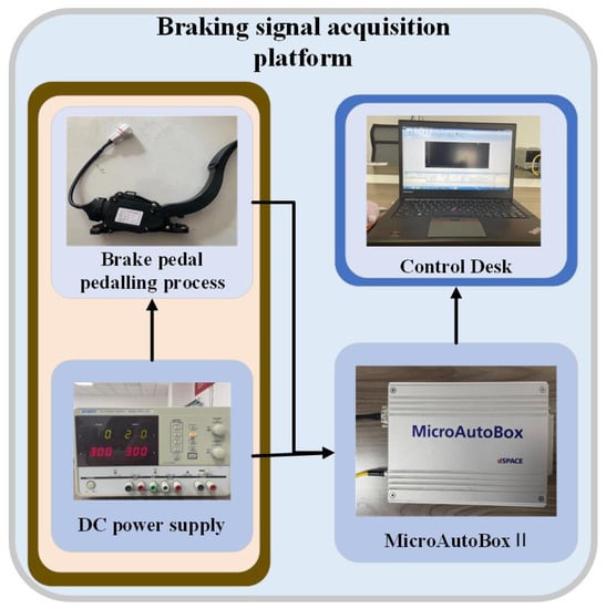
Figure 6.
Braking signal acquisition platform.
Due to the driver’s different braking requirements for different braking situations, the driver operates the brake pedal differently. In the deceleration braking condition, the brake pedal presents a small opening and maintains the small opening until the vehicle speed reaches the driver’s requirement. In the stopping condition, the driver slowly depresses the brake pedal to reduce the vehicle speed and quickly depresses the pedal when approaching the destination. Emergency conditions require the driver to press the pedal at maximum speed to maximize the pedal opening in the shortest possible time.
This paper uses the braking signal acquisition platform shown in Figure 6 to collect a total of 150 sets of braking data, 50 sets of each of the three types of braking intent data, with a sampling period of 0.01 s. From the braking signal acquisition results shown in Figure 1, it can be seen that the single braking behavior is short and the probability of the braking intent changing during this period is low, and the braking data can be used for braking intent identification.
4.2. Validation Analysis
The algorithm validation is divided into two aspects: first, to verify the validity of the sample entropy as a braking intention recognition parameter; and second, to verify the accuracy of the SSA-PNN algorithm.
In this paper, the accuracy rate and Kappa coefficient are used as evaluation indicators to measure the recognition effect, where the accuracy rate characterizes the proportion of correct classifications to the overall classification, and the Kappa coefficient is used to measure the classification accuracy and can measure the bias of the model classification.
To verify the validity of the sample entropy, the model validation was carried out by randomly dividing the data into training and test groups in the ratio of 4:1—120 sets of training data and 30 sets of test data—and comparing the accuracy of brake pedal position information, brake pedal position change rate, brake pedal speed change rate, and sample entropy as features to identify the braking intention. The recognition algorithm was a probabilistic neural network. Brake pedal position information can be directly captured by the platform shown in Figure 6, and other time-domain features such as pedal velocity and acceleration can be obtained via derivation. The obtained time-domain features with sample entropy are used as inputs to unify the recognition using an unoptimized probabilistic neural network. The PNN is first trained by 120 training samples with labels, and then, 30 unlabeled sets of test samples are inputted to validate the validity of the sample entropy using the recognition results and Kappa coefficients. The recognition results are shown in Table 1.

Table 1.
Recognition results for different features.
According to the results in Table 1, the recognition accuracy using the pedal position change rate and speed change rate as features is only 86.67% and 83.33% with Kappa coefficients of 0.7796 and 0.7463, which is a low recognition accuracy. The recognition accuracy using pedal position information is 90% with a Kappa coefficient of 0.8387, which is an improvement compared to the previous accuracy. The recognition accuracy using sample entropy as a feature is 93.33% with a Kapp coefficient of 0.8982, a further improvement compared to time-domain features such as position information, position change rate, and speed change rate. The results validate the effectiveness of sample entropy as a braking intention recognition parameter.
In order to verify the accuracy of the recognition algorithm, a random ratio of 7:3 was used to allocate the samples. A BP neural network, support vector machine (SVM), random forest algorithm, probabilistic neural network (PNN), genetic algorithm optimized probabilistic neural network (GA-PNN), and sparrow search algorithm optimized probabilistic neural network (SSA-PNN) were used for braking intention recognition. The BP neural network [28] is a kind of error backpropagation algorithm based on the correction of the error of the neural network which can adaptively modify the weights to achieve the desired result. The SVM [29] is a common classifier that can be classified by the kernel method as nonlinear. The random forest algorithm is an integrated learning method that uses decision trees as estimators. The GA [30] and SSA are both intelligent optimization algorithms that search for the optimal solution to a global problem by simulating the laws of nature in a continuous iterative manner. The parameter settings of the comparison algorithms are shown in Table 2, and the brake recognition results are shown in Table 3.
Table 2.
Parameterization of the algorithms.
Table 3.
Recognition results of different algorithms.
According to the results in Table 2, without optimization, the probabilistic neural network has better recognition results compared to the BP neural network, SVM, and random forest algorithms, with accuracy and Kappa coefficients of 93.33% and 0.9011, respectively, indicating that the PNN is more suitable than other algorithms for the accurate recognition of intentions with a smaller sample size. The results of the optimized probabilistic neural networks were better than the unoptimized results, with GA-PNN achieving 95.56% accuracy and a kappa coefficient of 0.9334. SSA-PNN achieved 97.78% accuracy and a kappa coefficient of 0.9667. From the confusion matrix shown in Figure 7, it can be visually compared that SSA-PNN has higher accuracy in intention recognition, while the errors mainly occur in the recognition of the second and third types of errors.
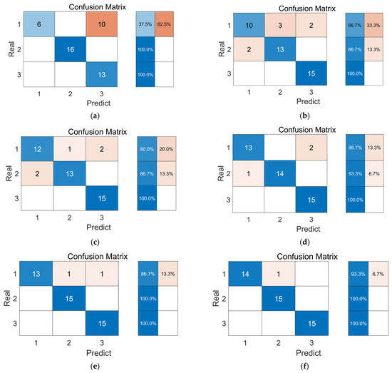
Figure 7.
Recognition results of different algorithms. (a) Random Forest; (b) BP; (c) SVM; (d) PNN; (e) GA-PNN; (f) SSA-PNN.
To rule out chance and further validate the advantages of SSA-PNN, 15 sets of validation were performed, and the identification results are shown in Figure 8.
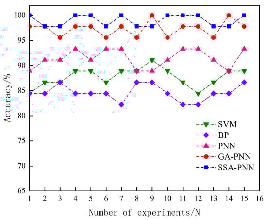
Figure 8.
Comparison of different algorithms over multiple trials.
The results in Figure 8 show that the SSA-PNN algorithm correctly identified all the results in 8 out of 15 trials, with a minimum accuracy of 97.78% and an average recognition accuracy of 98.86%. The average accuracy of the GA-PNN, PNN, BP, and SVM algorithms were 96.34%, 91.41%, 84.59%, and 87.71%, respectively. It can be seen that the SSA-PNN recognition accuracy is better than the other algorithms.
5. Conclusions
The accurate recognition of a driver’s braking intention can effectively formulate the regenerative braking control strategy of electric vehicles and improve the range of electric vehicles. In this paper, a braking intention recognition model based on sample entropy and a probabilistic neural network are proposed and experimentally verified to address the problem of how to accurately identify a driver’s braking intention.
- (1)
- Through the analysis of the experimental results, the effectiveness of using the sample entropy of the braking signal as the recognition feature is verified. Compared with the time-domain features such as pedal position, speed, and speed change rate, the sample entropy can identify the braking intention more effectively.
- (2)
- Compared with traditional machine learning algorithms, the SSA-PNN braking intention recognition algorithm proposed in this paper has higher braking intention recognition accuracy and can effectively achieve the accurate determination of braking intention.
- (3)
- In this paper, the SSA-PNN recognition model featuring sample entropy is constructed through the study of brake intention feature parameters and the recognition model, which improves the accuracy of brake intention recognition. However, there are still some shortcomings in this paper. The method only focuses on the accuracy of recognition and ignores the consideration of real time. In addition, further research is needed on how to extract braking signal features more accurately and quickly to improve the accuracy of braking intentions.
Author Contributions
Conceptualization, J.W. and H.Z.; investigation, H.Z.; methodology, J.W. and H.Z.; project administration, X.F.; resources, X.F.; software, Z.L. and X.F.; supervision, J.W.; validation, J.W.; writing—original draft, H.Z. and Z.L.; writing—review and editing, H.Z. and Z.L. All authors have read and agreed to the published version of the manuscript.
Funding
This work was supported in part by the Technological Innovation Guidance Project of Shaaxi, under Grant S2022-YD-QFY-0027; the Key Research and Development Project of Weinan, under Grant ZDYFJH-115; and the Key Research and Development Project of Shaanxi, under Grant 2023-YBGY-335.
Data Availability Statement
Data sharing not applicable.
Conflicts of Interest
The authors declare no conflict of interest.
References
- Zhou, H.; Niu, Z. Recognition of Driver’s Braking Intention Based on Extreme Learning Machine. Automob. Technol. 2021, 11, 30–34. [Google Scholar]
- Zhu, L.; Li, S.; Li, Y.; Wang, M.; Zhang, C.; Li, Y.; Yao, J.; Ji, H. Analysis of braking intention based on fNIRS in driving simulation experiments. IET Intell. Transp. Syst. 2019, 13, 1181–1189. [Google Scholar] [CrossRef]
- Li, M.; Wang, W.; Liu, Z.; Qiu, M.; Qu, D. Driver behavior and intention recognition based on wavelet denoising and bayesian theory. Sustainability 2022, 14, 6901. [Google Scholar] [CrossRef]
- Zheng, H. Braking intention recognition algorithm based on electronic braking system in commercial vehicles. Int. J. Heavy Veh. Syst. 2019, 26, 268–290. [Google Scholar] [CrossRef]
- Liu, J.; Zhang, X. Relationship among braking pedal displacement, braking In-tensity and braking strength in regenerative braking process of electric Vehicle. Sci. Technol. Eng. 2018, 18, 317–325. [Google Scholar]
- Tang, J.; Zuo, Y. Braking Intention Recognition Method Based on the Fuzzy Neural Network. Wirel. Commun. Mob. Comput. 2022, 2022, 2503311. [Google Scholar] [CrossRef]
- Lei, Y.; Zhang, Y.; Fu, Y.; Liu, K. Research on adaptive gearshift decision method based on driving intention recognition. Adv. Mech. Eng. 2018, 10, 1–12. [Google Scholar] [CrossRef]
- Wang, B.; Tang, X.; Wang, L.; Yang, S.; Ma, L. Braking intention identification method for electric vehicles based on EEMD and entropy theory. Automot. Eng. 2018, 40, 936–941. [Google Scholar]
- Wang, S.; Zhao, X.; Yu, Q.; Yuan, T. Identification of driver braking intention based on long short-term memory (LSTM) network. IEEE Access 2020, 8, 180422–180432. [Google Scholar] [CrossRef]
- Xing, Z. Driver’s intention recognition algorithm based on recessive Markoff model. J. Intell. Fuzzy Syst. 2020, 38, 1603–1614. [Google Scholar] [CrossRef]
- Li, X.; Zhang, X. Recognition Method of Braking Intention of Electric Vehicles Based on ABC-SVM Algorithm. China Mech. Eng. 2021, 32, 2125. [Google Scholar]
- Xin, G.; Guo, P. Research on key technologies of driving intention identification for commercial vehicle based on HMM-SVM. In Proceedings of the 2019 Chinese Automation Congress (CAC), Hangzhou, China, 22–24 November 2019; pp. 4941–4946. [Google Scholar]
- Zhao, X.; Wang, S.; Ma, J.; Yu, Q.; Gao, Q.; Yu, M. Identification of driver’s braking intention based on a hybrid model of GHMM and GGAP-RBFNN. Neural Comput. Appl. 2019, 31, 161–174. [Google Scholar] [CrossRef]
- Xu, S.; Zhao, X.; Yang, N.; Bai, Z. Control strategy of braking energy recovery for range-extended electric commercial vehicles by considering braking intention recognition and electropneumatic braking compensation. Energy Technol. 2020, 8, 2000407. [Google Scholar] [CrossRef]
- Li, H.; Xu, Y.; An, D.; Zhang, L. Application of a flat variational modal decomposition algorithm in fault diagnosis of rolling bearings. J. Low Freq. Noise Vib. Act. Control. 2020, 39, 335–351. [Google Scholar] [CrossRef]
- Chen, S.; Peng, K.; Zhou, P. Review of signal decomposition theory and its applications in machine fault diagnosis. J. Mech. Eng. 2020, 56, 91–107. [Google Scholar]
- Zhang, W.; Li, j.; Chen, W. A compound fault feature separation method of rolling bearings based on VMD optimized by the bat algorithm. J. Vib. Shock. 2022, 41, 133–141. [Google Scholar] [CrossRef]
- Zhang, J.; Hou, G.; Wang, H.; Zhao, Y.; Huang, J. Operation feature extraction of flood discharge structure based on improved variational mode decomposition and variance dedication rate. J. Vib. Control. 2020, 26, 229–240. [Google Scholar] [CrossRef]
- Meng, Z.; Wang, X.; Liu, J.; Fan, F. An adaptive spectrum segmentation-based optimized VMD method and its application in rolling bearing fault diagnosis. Meas. Sci. Technol. 2022, 33, 125107. [Google Scholar] [CrossRef]
- Pang, C.; Jiang, Y.; Liao, C.; Wu, T.; Jing, W. Automatic recognition of natural earthquaks and artificial blasting based on the sample entropy of the Mel frequency cepstrum coefficient and support vector machine optimized by gray wolf optimization. China Earthq. Eng. J. 2022, 44, 1169–1175. [Google Scholar] [CrossRef]
- Javaid, M.; Abbas, M.; Liu, J. Topological properties of four-layered neural networks. J. Artif. Intell. Soft Comput. Res. 2019, 9, 111–122. [Google Scholar] [CrossRef]
- Sharkawy, A.N. Principle of neural network and its main types: Review. J. Adv. Appl. Comput. Math. 2020, 7, 8–19. [Google Scholar] [CrossRef]
- Liu, B.; Cao, M. Application of Probabilistic Neural Network in Fault Diagnosis of Turbo-generator. Softw. Guide 2019, 18, 10. [Google Scholar]
- Wang, C.; Tang, Z.; Wu, X.; Li, C.; Zhang, H. Semi-supervised Land Use Classification Based on Particle Swarm Optimization Probabilistic Neural Network. Trans. Chin. Soc. Agric. Mach. 2022, 53, 2. [Google Scholar]
- Xue, J.; Shen, B. A novel swarm intelligence optimization approach: Sparrow search algorithm. Syst. Sci. Control Eng. 2020, 8, 22–34. [Google Scholar] [CrossRef]
- Bai, W.; Jia, X.; Lv, T. Application of Improved Sparrow Search Algorithms in Three-dimensional Path Planning. Control Eng. China 2022, 29, 10. [Google Scholar]
- Pan, H.; Guo, X.; Pei, X.; Pan, J.; Zhang, J. Research on Regenerative Braking Control Strategy of Distributed EV Based on Braking Intention; SAE Technical Paper; SAE International: Warrendale, PA, USA, 2018. [Google Scholar]
- He, K.; Jiang, L. Research on DC Electronic Load System Based on BP Neural Network PID Control. Acad. J. Eng. Technol. Sci. 2022, 5, 56–61. [Google Scholar] [CrossRef]
- Wu, Y.; Tao, G. Application of a New Loss Function-Based Support Vector Machine Algorithm in Quality Control of Measurement Observation Data. Math. Probl. Eng. 2022, 2022, 7266719. [Google Scholar] [CrossRef]
- Xu, L.; Hou, L.; Zhu, Z.; Li, Y.; Liu, J.; Lei, T.; Wu, X. Mid-term prediction of electrical energy consumption for crude oil pipelines using a hybrid algorithm of support vector machine and genetic algorithm. Energy 2021, 222, 119955. [Google Scholar] [CrossRef]
Disclaimer/Publisher’s Note: The statements, opinions and data contained in all publications are solely those of the individual author(s) and contributor(s) and not of MDPI and/or the editor(s). MDPI and/or the editor(s) disclaim responsibility for any injury to people or property resulting from any ideas, methods, instructions or products referred to in the content. |
© 2023 by the authors. Licensee MDPI, Basel, Switzerland. This article is an open access article distributed under the terms and conditions of the Creative Commons Attribution (CC BY) license (https://creativecommons.org/licenses/by/4.0/).