Article

High-Reliability Rotor Position Detection Method for Sensorless Control of Synchronous Condenser

1
School of Electrical Engineering, Southeast University, Nanjing 210094, China
2
Nari Electric Co., Ltd., Nanjing 211102, China
*
Author to whom correspondence should be addressed.
World Electr. Veh. J. 2023, 14(10), 299; https://doi.org/10.3390/wevj14100299
Submission received: 18 July 2023 / Revised: 29 August 2023 / Accepted: 11 October 2023 / Published: 21 October 2023

Abstract

:
Static frequency converters (SFCs) are very important for starting the connection of synchronous capacitors to the power grid, which is beneficial for ensuring the impact of electric vehicle connection on the inertia of the power grid. In the traditional sensorless initial rotor position detection method, the signal-to-noise ratio of the induced voltage at the machine terminal is small, making it difficult to accurately extract the rotor position. In this study, a reliable initial position detection method for a sensorless-controlled synchronous machine drive is proposed. A step excitation voltage was applied to the excitation circuit before the motor was started, and the three-phase induction voltage at the terminals was sampled in real time. The sampling signal was processed in two ways: digital filter processing and stator flux calculation. The accuracy of the initial rotor position is determined by comparing the differences between the two results. This algorithm does not depend on additional hardware circuits and has fewer setting parameters; therefore, it is easy to apply in engineering applications. Finally, a comparative experiment was conducted using a real-time digital system (RTDS) to verify the feasibility and effectiveness of the proposed method. The proposed rotor position detection method can effectively improve the detection reliability and ensure the start-up reliability of SFCS.

1. Introduction

With the development of power systems, particularly ultra-high-voltage direct current transmission systems, the demand for reactive power sources has increased [1,2]. Concurrently, owing to the increase in renewable energy power generation and the continuous reduction in coal power generation, the power grid lacks dynamic reactive power support and the problem of voltage stability is becoming increasingly prominent. On the other hand, the increasing integration of electric vehicles in the distribution network weakens the inertia of the distribution network, while traditional compensation equipment does not have specific inertia support capabilities. Therefore, to strengthen the voltage support of power systems and improve the flexibility of power grid operation, synchronous condensers are increasingly used in power grids. Static frequency converters (SFCs) have attracted considerable attention as crucial equipment for starting the connections of synchronous condensers to the grid [3,4].
The SFC for a synchronous condenser is a current-source inverter for speed regulation of a synchronous motor. Accurate rotor position detection of a motor directly determines if an SFC can drive the motor to start normally [5]. With the development of measurement and control technology, electrical drives have begun to use the rotor position detection method without a mechanical position sensor. It reduces the workload of on-site maintenance and increases the requirements for system measurement accuracy and control algorithm reliability [6,7,8,9].
To detect the initial rotor position of a synchronous condenser, the control system generally applies a step excitation command to the rotor winding of the synchronous condenser and obtains the initial rotor position from the measured terminal-induced voltage [6,7]. However, the induced voltage at the machine terminal is small and superimposed with various noise interferences, and the signal-to-noise ratio (SNR) is also low. Therefore, the signal is weaker after the voltage transformation of the measuring circuit. Consequently, it is difficult to accurately extract the rotor position [10,11]. The earlier solution involves using a rotor position sensor but only performing the detection function in the low-speed stage [12,13]. The reliability problem has been solved to a certain extent; however, the mechanical position sensor has not yet been removed. With improvements in the computing power of the processor, researchers have proposed a method of injecting high-frequency signals to realize initial position detection [14,15,16]. However, this is not applicable to the inverter bridge of an SFC with thyristor as the core device. Errors in rotor initial position detection can cause damage to mechanical structures such as turning gears and should be avoided [6,10]. A low-speed forward rotation of a large Synchronous capacitor is driven by a barring device before starting. Before disengaging from the turning device (such as the initial rotation), reverse torque can not be applied to the static inverter starting unit as it is more strictly prohibited to drag the unit reverse rotation. Otherwise, the gear mechanism of the turning gear will be damaged destructively, which puts forward higher requirements for the accuracy and reliability of the initial position detection of the static inverter. For the rotor position detection in the phase of load commutation, the terminal voltage of the Synchronous condenser is close to the sine wave. The static inverter can adopt the control scheme of a constant commutation margin angle, and the commutation time is the zero-crossing time of terminal line voltage. Therefore, using a hardware circuit to detect the zero-crossing can form the trigger signal of the inverter, but the zero-crossing caused by interference is not accurate and the phase hysteresis caused by the conventional filtering algorithm needs to be addressed [8,13].
In order to solve the reliability problem of phase detection in the initial stage and operation stage of a static frequency converter, the corresponding anti-interference phase detection method is proposed to improve the accuracy of detection and ensure its operation control performance. In this study, a method based on the line voltage and flux is proposed to detect the initial rotor position. Digital filtering and flux calculations were used to measure the terminal voltage and rotor position, respectively, and the results were compared. When there is a large deviation between the calculation results of the two methods, it is judged that the initial rotor position calculation is abnormal, and the unit is forbidden from starting. Finally, the effectiveness of this method is verified using a real-time digital system (RTDS) simulation.

2. Dual Rotor Initial Position Detection Method

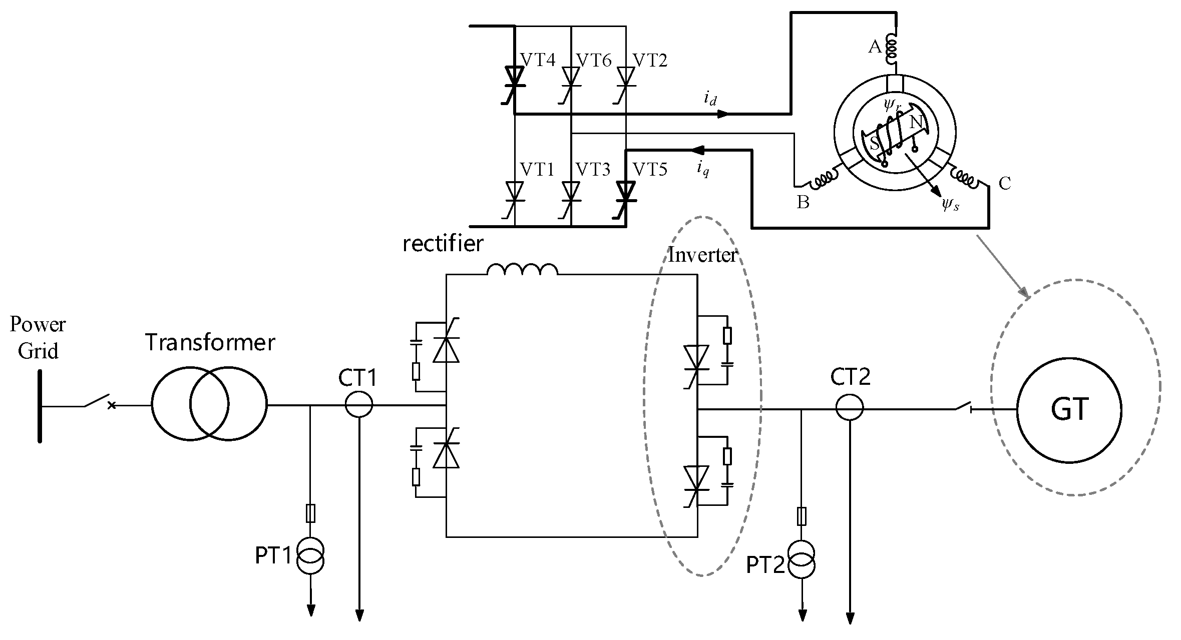
2.1. Start up Analysis of SFC

A schematic diagram of the rotor position detection is shown in Figure 1. As shown in the figure, the control system applies a step excitation voltage command to the rotor winding of the motor and extracts the initial rotor position from the induced voltage measured at the terminals. However, the induced voltage at the machine terminals is small and superimposed with various noise interferences, and the SNR is low. Therefore, the signal becomes weaker after the voltage transformation of the measuring circuit.
According to the operating principle of a static frequency converter, there are six possible thyristor combinations that form six possible electrical positions in the magnetic field generated by the stator current. As shown in Figure 2, to ensure that the initial acceleration torque is sufficiently large, it is necessary to select the thyristor combination that requires conduction according to the initial position [17], such that the magnetic field formed by the stator current is ahead of the rotor magnetic field, and there is an appropriate angle between them.
An incorrect judgment of the initial rotor position will result in unit start-up failure and even reverse rotation. In certain special applications, this may damage the mechanical structure, such as the turning gear mechanism, which should be avoided. However, common sensorless rotor position detection methods have several problems, such as a single calculation method and lack of multi-algorithm mutual verification. In Figure 2, GT stands for generator, PT for voltage transformer, and CT for current transformer.

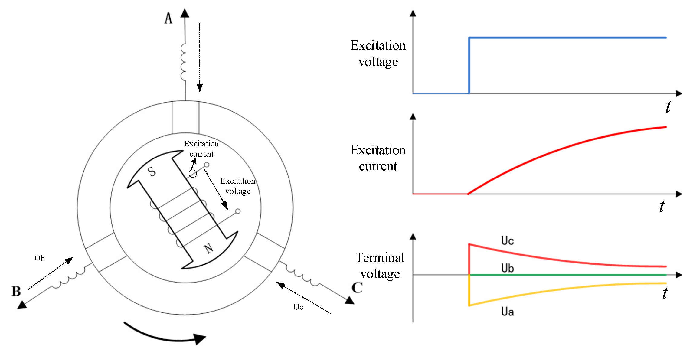
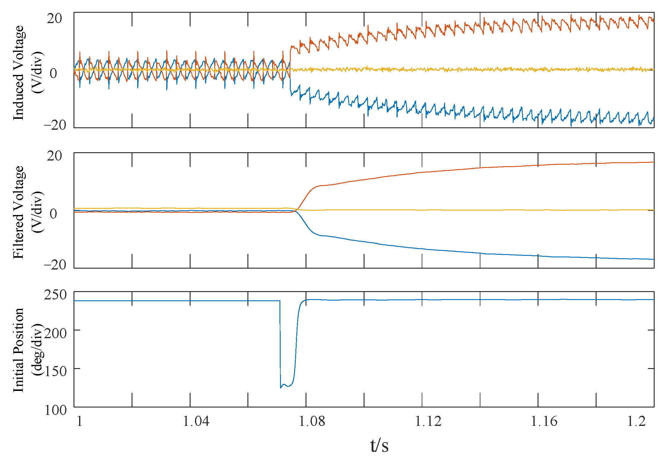
2.2. Voltage Detection Method

To ensure the successful start-up of a synchronous motor, it is necessary to accurately measure the initial rotor position when the motor is stationary. On this basis, subsequent start-up control can be performed correctly. Owing to the limitation of the voltage step signal and motor parameters, the value of the voltage signal induced by the motor stator is relatively small. There are also various interference signals and the signal waveform is poor. Moreover, the signal is weakened by the measuring circuit, and the size of the useful signal is comparable to the interference signal, which easily results in a calculation error of the initial position of the motor rotor, causing motor start failure and affecting normal industrial production. Based on real and effective line voltage signals, the rotor position is accurately calculated using the line voltage calculation formula, which creates conditions for the successful start-up of the motor.
The voltage detection method is illustrated in Figure 3. The SNR of the stator-induced line voltage detected by the voltage sensor is low; therefore, a low-pass digital filter was used to filter the interference and amplify the signal appropriately. Subsequently, the stator-induced voltage amplitude was obtained using the line voltage induced by the stator of the synchronous condenser. Finally, the initial position information is obtained using the line voltage amplitude and angle calculation formulas. Compared with existing rotor position detection methods [8,10], this method is more effective in extracting line voltage information, which accurately reflects the synchronous condenser position of the rotor. Thus, the relative position of the rotor at rest can be accurately calculated based on the line voltage.
The line voltage signal generated by the motor stator was measured and a low-pass digital filter was used to filter the interference and amplify the signal appropriately. The transfer function of the filter is
F ( z ) = K G 1 ( z ) G 2 ( z )
In Equation (1),
G ( z ) = b 0 + b 1 z 1 + b 2 z 2 a 0 + a 1 z 1 + a 2 z 2
where b0, b1, b2, a0, a1, and a2 are the filter coefficients. The filter G(z) described in Equation (2) is a second-order low-pass filter, which is used to filter out the high-frequency signal in the line voltage signal, and K in Equation (1) is the amplification factor, which is used to properly amplify the filtered line voltage signal.
Once the original voltage signals uabp, ubcp, and ucap were filtered using the above filters, the uAB, uBC, and uCA signals were generated, and the instantaneous values uABm, uBCm, and uCAm were obtained.
When the excitation current changes, a three-phase voltage is induced at the generator end, which includes rotor position information, namely:
[ u a u b u c ] = [ d d t [ m a f cos θ i f ] d d t [ m b f cos ( θ 120 ° ) i f ] d d t [ m c f cos ( θ + 120 ° ) i f ] ]
m a f = m b f = m c f = ω ω f λ ad
In the formula, ua, ub, and uc are the terminal voltages of the synchronous condenser, θ Is the rotor position angle, maf, mbf, and mcf are the maximum mutual inductance between the stator and rotor, and ω and ωf are the equivalent turns of the stator and rotor windings, respectively, and λad is the permeability of the d axis breath magnetic flux path.
When the motor speed is zero, the terminal voltage is only generated by the change in excitation current. From Equation (3), it can be obtained that
{ sin θ = u ABm 3 m af d i f d t cos θ = u BCm u CAm 3 m af d i f d t
θ 1 = arctan ( 3 × u B C max u C A max u A B max )
Thus, the position angle of the rotor in the entire space can be determined by Equations (5) and (6).

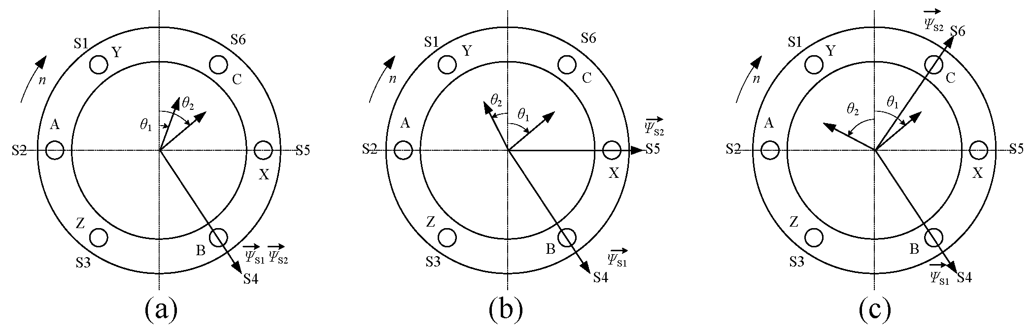
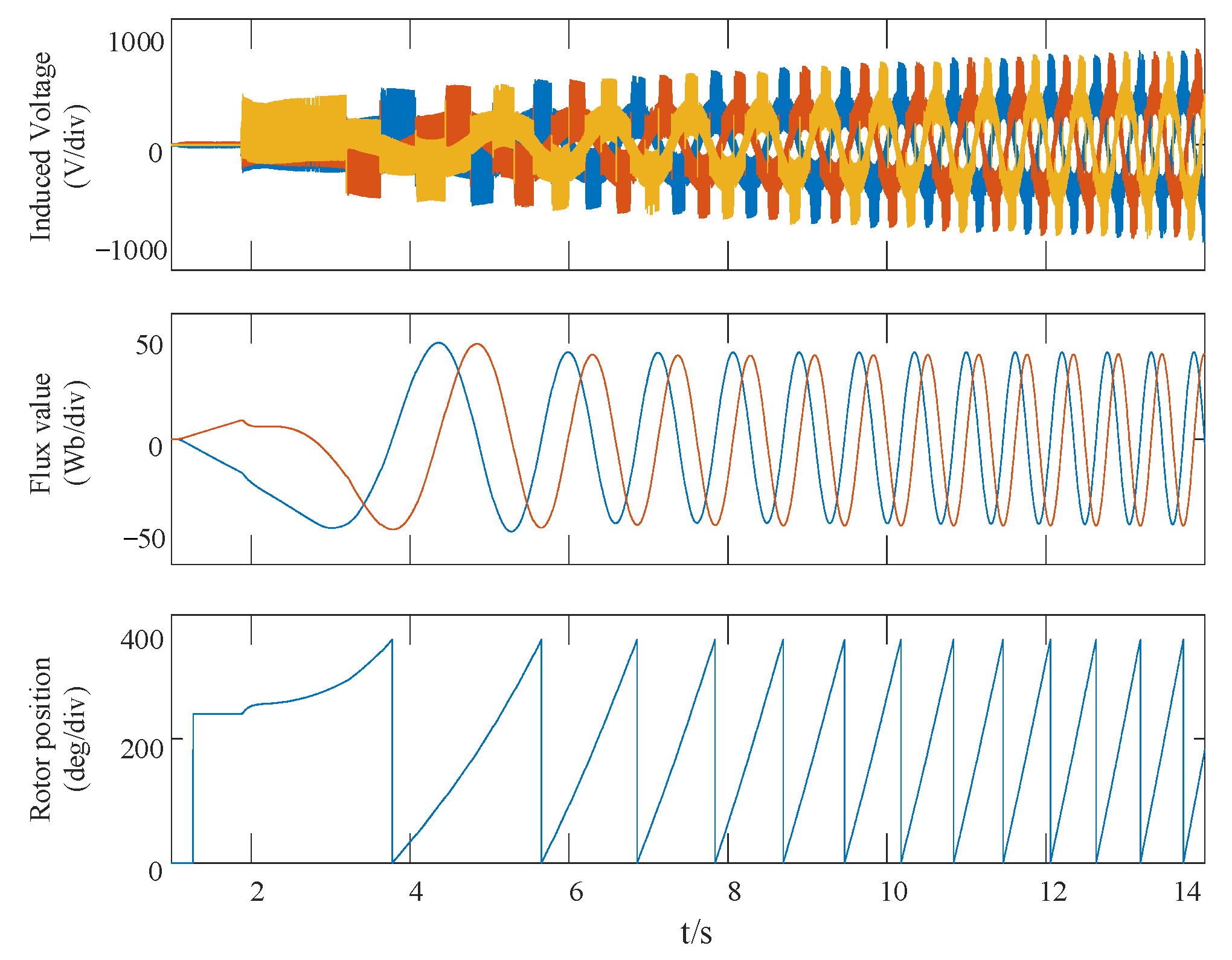
2.3. Magnetic Flux Detection Method

The rotor initial position detection based on the flux algorithm is used to calculate the unit flux using the voltage model method while the excitation current is suddenly applied. According to the real-time calculated magnetic flux ψ α and ψ β , the rotor position can be calculated using θ 2 = arctan ( ψ β / ψ α ) . The induction voltage signal of the original generator terminal is integrated to calculate the stator flux. According to the relationship between the magnetic flux and voltage of the synchronous motor, Equation (7) can be deduced. Moreover, the method can suppress the integral bias caused by zero drift; the algorithm block diagram is shown in Figure 4.
The variables uα and uβ denote the induced voltage components of the α-β axis generator terminal, and λmax is set according to the step value of excitation voltage.
{ ψ α = 1 s + ω c u α + ω c s + ω c × λ lim × λ α ψ α 2 + ψ β 2 ψ β = 1 s + ω c u β + ω c s + ω c × λ lim × λ β ψ α 2 + ψ β 2
In Equation (7),
λ lim = min { ψ α 2 + ψ β 2 , λ max } ,   cos θ 2 = λ β ψ α 2 + ψ β 2 ,   sin θ 2 = λ α ψ α 2 + ψ β 2
where ωc denotes the cut-off frequency of the first-order low-pass filter.
If there is a deviation between θ1 and θ2, and VTn1, VTm1, VTn2, and VTm2 (n = 1,3,5; m = 2,4,6) are the same, it is judged that the rotor position calculation is successful, the system is unlocked, and the converter is started for the first time, as illustrated in Figure 5a. The variables VTn1 and VTm1 denote the thyristor numbers that θ1 needs to turn on, and VTn2 and VTm2 are the thyristor numbers that θ2 needs to turn on. Otherwise, it is determined that the calculation of the rotor position fails and the startup is terminated, as shown in Figure 5b,c. Moreover, S1–S6 indicate the possible directions of the magnetic field axes formed by the stator currents in space. XYZ represents the port for the connection port of the stator three-phase winding, and ABC represents the input current port of the stator three-phase winding.

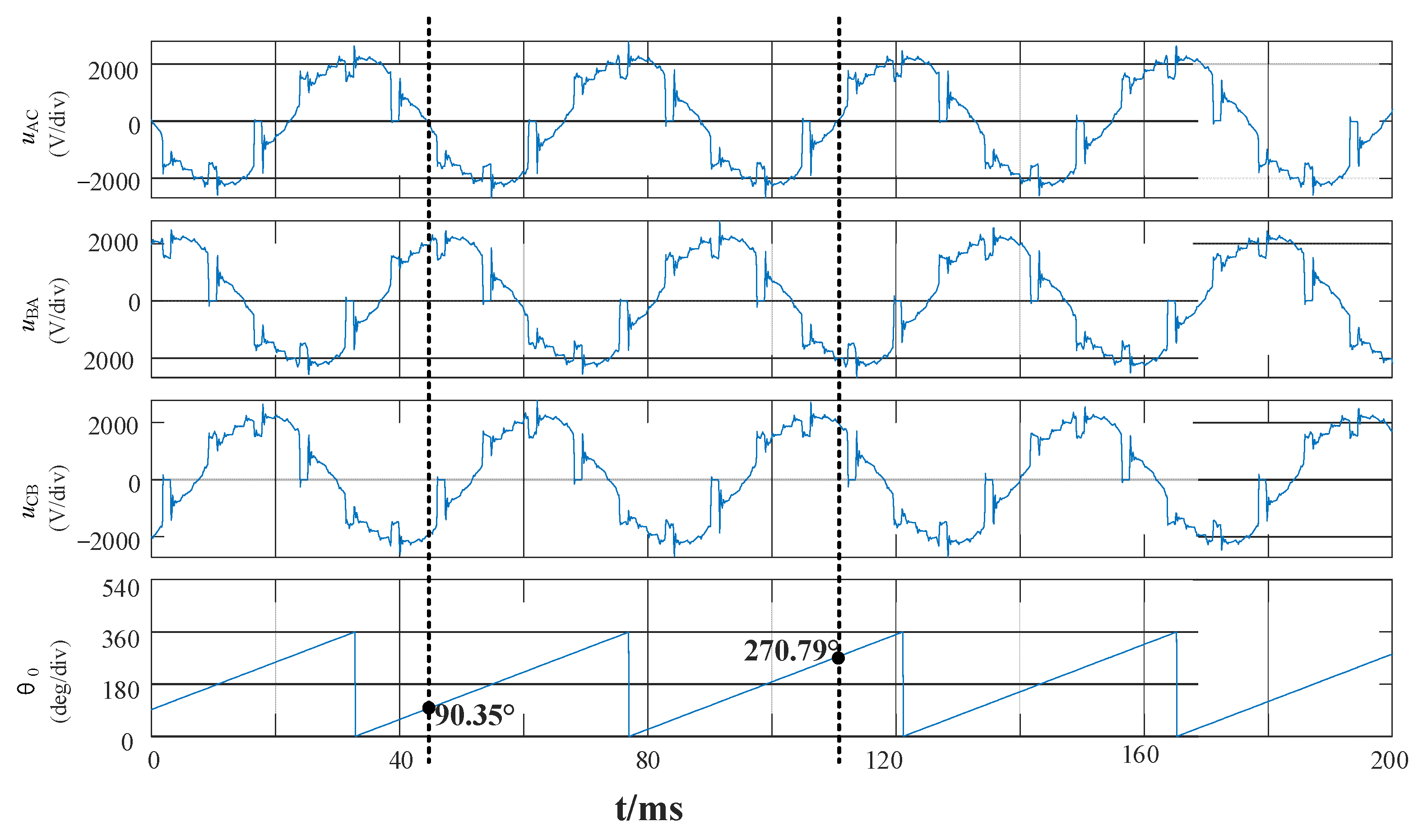
3. Method for Detecting Rotor Position during Operation

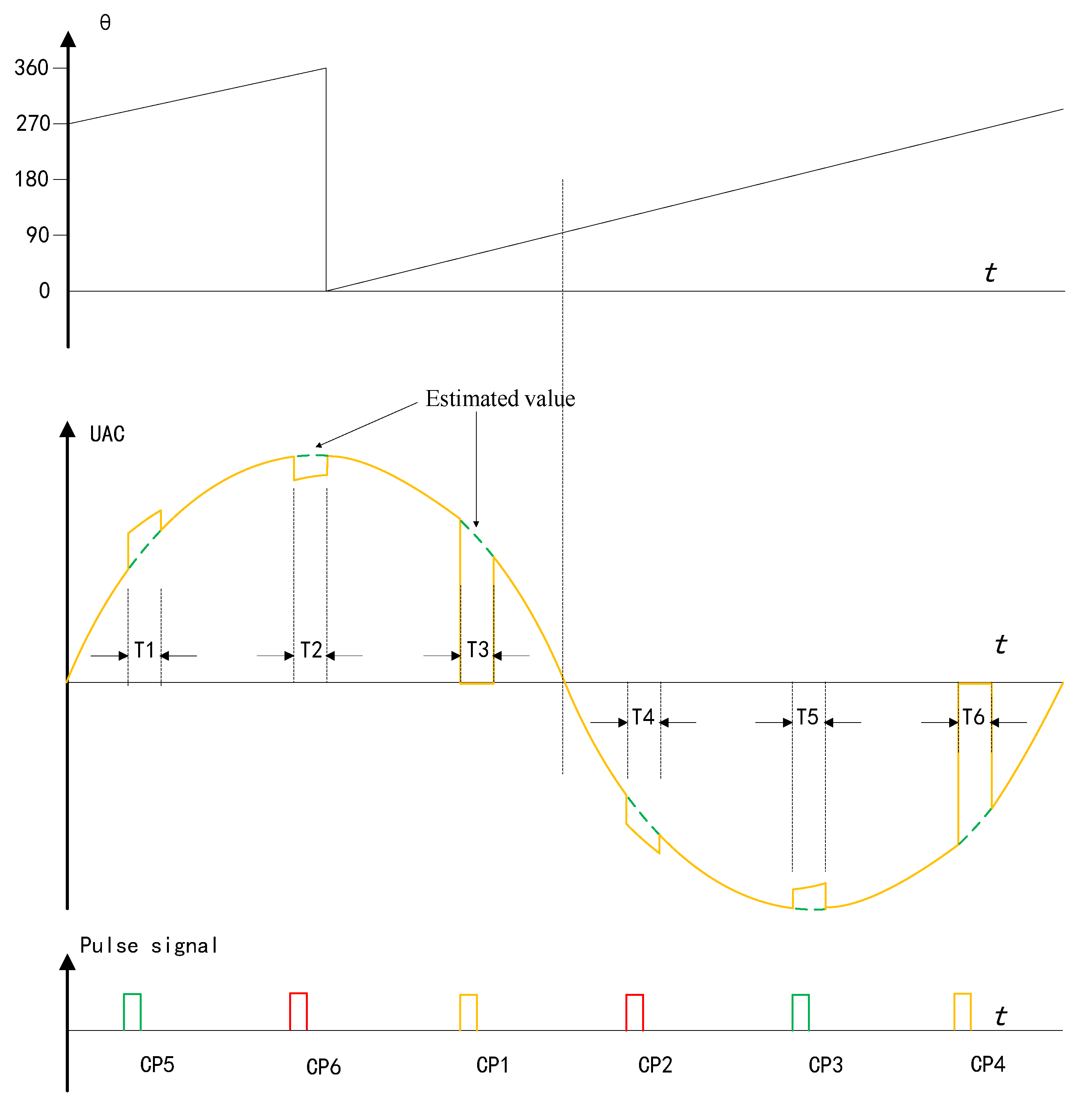
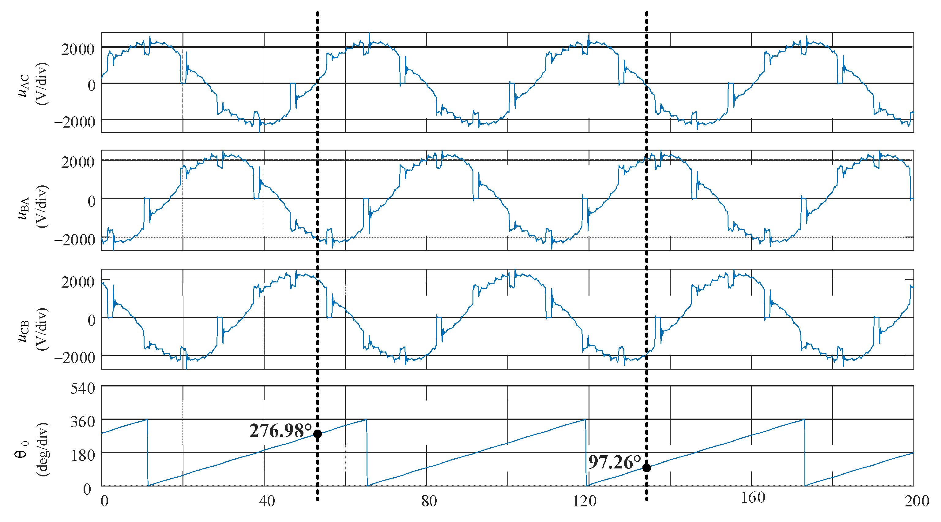
3.1. Synchronous Phase Compensation

Affected by the commutation process of the thyristor, the synchronous signal measured by the sampling phase voltage transformers (PTs) of the converter has a large distortion and the frequency varies over a large range, as shown in Figure 6. Generally, A SFC adopts the form of high–low voltage. The output side was not isolated by an output transformer, and the terminal voltage was the same as the anode line voltage of the converter.
A constant commutation margin angle control is often used to improve the power factor of the output side of the SFC and ensure reliable operation of the converter. However, accurate measurement of the zero-crossing point of the synchronous signal (line voltage) of the converter is the basis for reliable operation and accurate control of the SFC inverter.
A conventional linear filtering algorithm can obtain a signal in a specific frequency band, such as the fundamental component of the original synchronized signal. However, owing to the asymmetry of the line voltage (synchronous signal) waveform, there is a deviation between the fundamental phase and original waveform, and the deviation changes under different operating conditions. As illustrated in Figure 6, it is difficult to accurately determine the synchronization phase.
To eliminate the influence of waveform distortion on the frequency conversion synchronous phase detection of the SFC system, at the trigger pulse moment, as shown in Figure 6, the original voltage waveform is processed by sinusoidal interpolation (Equation (8)). This is performed to obtain an approximately sinusoidal voltage waveform. The compensated signal is then phase-locked with a strong anti-interference software phase-locked loop.
U L = { U m sin ( a p 3 + n × ω m × T s ) T 1 U m sin ( a + p 3 + n × ω m × T s ) T 2 U m sin ( a + n × ω m × T s ) T 3 U m sin ( a p 3 + n × ω m × T s ) T 4 U m sin ( a + p 3 + n × ω m × T s ) T 5 U m sin ( a + n × ω m × T s ) T 6 U A C O t h e r   S t a g e
where Ts denotes the sampling period of the controller and n = [ 0 , I N T ( t μ ) T s + 1 ] represents the number of sampling points in the selected interpolation interval. The variable ωm denotes the frequency of the voltage signal.
The algorithm performs sinusoidal interpolation in the selected interval, eliminating the influence of synchronous voltage distortion on the synchronous phase detection. The filtered voltage exhibited the following characteristics:
(1)
Waveform distortion is significantly reduced and symmetrical.
(2)
The zero-crossing time is the same as that of the original signal without a phase offset.
It can ensure a real-time and accurate phase-locked frequency conversion synchronous signal of the phase-locked loop algorithm and adapt to the frequency conversion operating conditions of the static inverter.

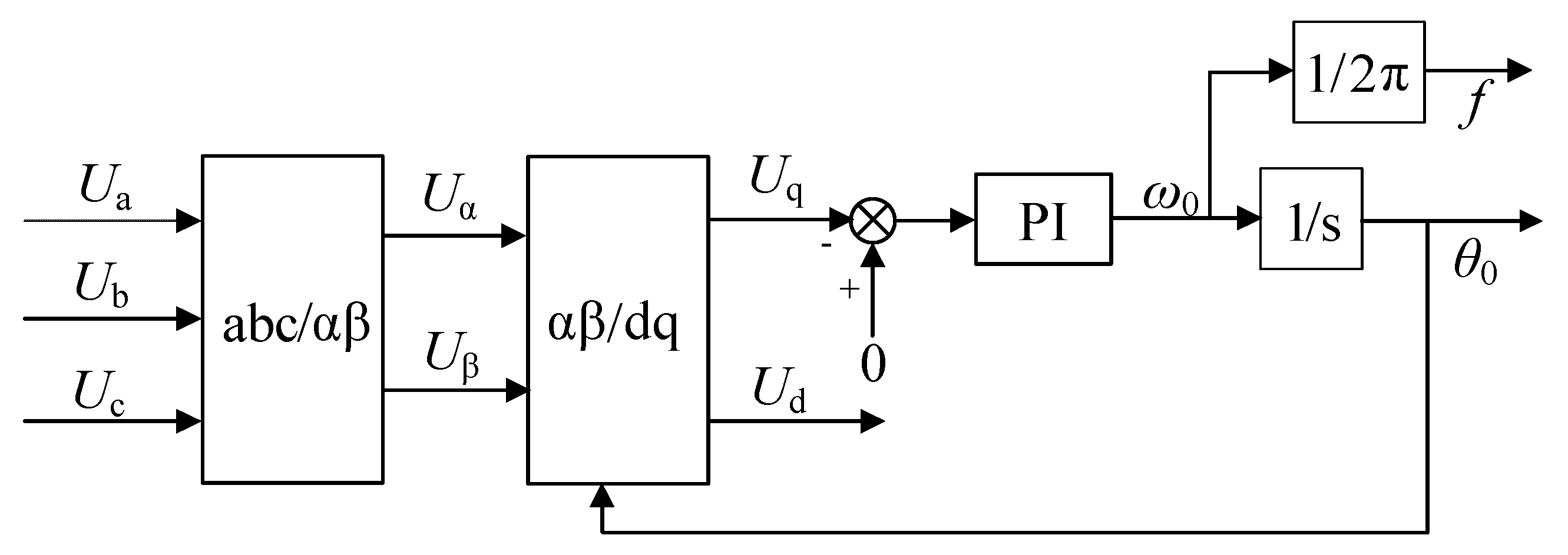
3.2. Software Phase-Locked Loop Based on Rotating Coordinate System

The position information of the synchronous motor can only be obtained from the sampled data processed by the synchronous phase via a phase-lock loop. A phase-locked loop system uses phase feedback to achieve more accurate control. It can also achieve tracking control of constant frequency signals. Simultaneously, this control can improve tracking accuracy and sensitivity. In contrast to other phase-locked loops, software phase-locked loops have the advantages of extremely rich degrees of freedom and maximum expansion capability. In practical applications, through some practical designs, the software phase-locked loop can realize the functions of the general phase-locked loop and break through the effects achieved by the analog and hardware phase-locked loops.
The specific implementation of the PLL module based on a rotating coordinate system is depicted in Figure 7. Following the coordinate transformation of abc/dq, the grid voltage is converted to the dq rotating coordinate system. Subsequently, proportional-integral (PI) regulation is adopted to determine the phase of the input voltage vector. The positive sequence component of the grid voltage is selected to effectively suppress the influence of the amplitude and frequency fluctuations of the grid voltage on the phase-locked loop. The variables Ua, Ub, and Uc represent the input voltage, and the three-phase voltage in the abc coordinate system is transformed into αβ. The two-phase voltage in the coordinate system is transformed into Ud and Uq two-phase voltages in the rotating coordinate system, where ω0 and θ0 represent the angular frequency and phase angle, respectively, of the rotating coordinate system.

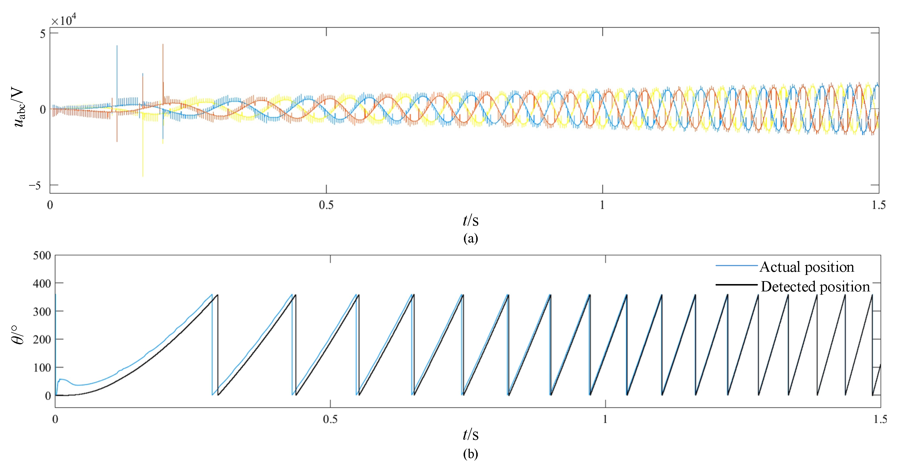
4. RTDS Verification

RTDS experiments were set up to verify the effectiveness of the proposed dual initial position detection method. The specific parameters of SFCS and SC are listed in Table 1. As shown in Figure 8, the platform includes an RTDS real-time digital emulator, an input/output (IO) interface card, and an SFC controller. The SFC controller comprises three parts: an SFC control unit, an IO sampling unit, and an intelligent IO control unit. The core of the SFC controller comprises an SFC control unit and an SFC IO sampling unit that perform electrical data acquisition and calculation, rotor position detection, bridge synchronous signal formation, unit speed closed-loop control (including bridge trigger control), bridge synchronous signal formation, bridge trigger control, system protection, and system monitoring. The intelligent IO control device sends the switching quantities inside and outside the system directly via optical fiber or through a logical operation to the regulating device and receives the control signals transmitted by the regulating device directly or through a logical operation.
The parameters of the filter and PI controller are shown in Table 2. Figure 9 shows a waveform using the voltage detection method, including the induction voltage at the SC terminal, the filtered induction voltage, and the initial rotor position detected value. As shown in the diagram, the voltage detection method designed in this study has a good filtering effect. The harmonic content of the filtered induction voltage is also extremely low, and the initial rotor position can be accurately detected. Figure 10 illustrates the waveform of the flux calculation method, including the induction voltage of the SC machine, the flux value in the αβ coordinate, and the rotor position angle. It can be observed from the diagram that the flux calculation method designed in this study can effectively track the real-time position of the rotor. Not only can it be used to detect the initial position, but it also provides a good basis for the phase-locked loop in the following operation. Figure 11 shows the waveform obtained using the dual-rotor initial position detection method. The initial position detected by the voltage detection method is 255.88°, whereas the initial position detected by the flux detection method is 257.35°. Compared to the initial rotor position calculated by the two algorithms, the deviation of the two algorithms is less than 5°. Thus, the detection is successful and the SFC starts, ensuring forward rotation of the motor. From the RTDS simulation results, we can observe that the proposed dual-rotor initial position detection method can avoid the uncertainties presented by the low SNR of the single detection method and effectively improve the reliability of SC startup.
Figure 12 and Figure 13 show the phase-locked loop of the rotating coordinate system for detecting the rotor position during operation. Figure 12 illustrates the rotor position results without synchronous phase compensation. Affected by the thyristor commutation process, the synchronized signal detected by the inverter bridge PT exhibited a large distortion, and the frequency varied over a large range. The results without phase compensation show a large detection deviation. As shown by the dotted line in Figure 12, The detection result at the zero-crossing position (theoretical value of 270°) on the rising edge of the bridge Uac is 276.98°. The detection result at the zero-crossing point (theoretical value of 90°) of the descending edge of the bridge Uac is 97.26°, with a deviation of approximately 7°. This large deviation is not conducive to reliable operation and accurate control of the inverter bridge of the static inverter. Figure 13 presents the rotor position detection results obtained using synchronous phase compensation. As the synchronous compensation algorithm performs sinusoidal interpolation at the selected interval, it can effectively eliminate the effect of synchronous voltage distortion on synchronous phase detection. As shown by the dotted line in Figure 13, The detection result at the zero-crossing position on the descending edge of the bridge Uac is 90.35°, whereas the detection result at the zero-crossing position on the rising edge of the bridge Uac is 270.79°.
The whole process is shown in Figure 14. The synchronous condenser is started from zero rotation speed, and within a time range of 1.5 s, the amplitude and frequency of the terminal voltage are increasing. After the phase of the input voltage is locked by the phase-locked loop, the changes in the frequency and amplitude of the input signal do not disturb the PLL. The error between the position detected by the method proposed in this paper and the actual position angle of the rotor is kept within 1%, which can meet the needs of the sensorless control of static frequency converters. The simulation results show that the initial rotor position detection method can verify the deviation of the two methods, can effectively avoid inversion during start-up, and can improve the safety of large-scale synchronous motor starting. A method of synchronous phase compensation for the initial terminal voltage is proposed to improve the accuracy of rotor position detection. Compared with the methods in the literature, the computational workload is increased to a certain extent, but it provides an effective guarantee for the reliable starting of large-scale synchronous condensers.

5. Conclusions

In this study, the starting process of SFCS was analyzed and a highly reliable rotor position detection method was studied. In the starting stage, an initial rotor position detection method was proposed by combining two different signal processing methods. For the operation phase, a phase-locked loop with synchronous phase compensation was proposed. The following conclusions are drawn.
  • Two position detection methods are used to check each other, which can effectively avoid reverse rotation when the unit starts and improve the safety of large synchronous motors.
  • Synchronous phase compensation can effectively reduce the influence of a distorted waveform on detection accuracy and improve phase detection accuracy to within 1%, thus providing technical support for the high-performance control of SFCS.
  • The algorithm does not need additional hardware circuits, has few parameters, and can be easily applied in engineering.

Author Contributions

Conceptualization, X.S. and T.L.; methodology, X.S.; software, W.M.; validation, X.S. and T.L.; formal analysis, X.S.; data curation, X.S.; writing—original draft preparation, X.S.; writing—review and editing, J.Z.; visualization, X.S.; supervision, J.Z.; project administration, J.Z.; funding acquisition, J.Z. All authors have read and agreed to the published version of the manuscript.

Funding

The work is supported by the National Natural Science Foundation of China (NO. 51877042).

Data Availability Statement

Not applicable.

Conflicts of Interest

Teng Li and Mu are Employees of Nari Electric Co., LTD. The Paper Reflects The Views of the Scientis, and Not the Company.

References

  1. Ramachandra Sekhar, K.; Vinoth Kumar, N.; Harada, Y. Impact of renewable energy control center on voltage stability and transmission network efficiency in wind farm integrated grid. In Proceedings of the 2014 IEEE International Conference on Power Electronics, Drives and Energy Systems, Mumbai, India, 16–19 December 2014; pp. 1–6. [Google Scholar]
  2. Teleke, S.; Abdulahovic, T.; Thiringer, T.; Svensson, J. Dynamic Performance Comparison of Synchronous Condenser and SVC. IEEE Trans. Power Deliv. 2008, 23, 1606–1612. [Google Scholar] [CrossRef]
  3. Wang, Y.; Wang, L.; Jiang, Q. Impact of Synchronous Condenser on Sub/Super-Synchronous Oscillations in Wind Farms. IEEE Trans. Power Deliv. 2021, 36, 2075–2084. [Google Scholar] [CrossRef]
  4. Wang, P.; Mou, Q.; Liu, X.; Gu, W.; Chen, X. Start-Up Control of a Synchronous Condenser Integrated HVDC System With Power Electronics Based Static Frequency Converter. IEEE Access 2019, 7, 146914–146921. [Google Scholar] [CrossRef]
  5. Tan, J.; Xue, R.; Tan, H.; Zhang, T.; Zhao, Y.; Zhao, B.; Wu, S.; Zhai, Y.; Dang, H. Design and Experimental Investigations on the Helium Circulating Cooling System Operating at Around 20 K for a 300-kvar Class HTS Dynamic Synchronous Condenser. IEEE Trans. Appl. Supercond. 2022, 32, 5400405. [Google Scholar] [CrossRef]
  6. Hadavi, S.; Rathnayake, D.B.; Jayasinghe, G.; Mehrizi-Sani, A.; Bahrani, B. A Robust Exciter Controller Design for Synchronous Condensers in Weak Grids. IEEE Trans. Power Syst. 2022, 37, 1857–1867. [Google Scholar] [CrossRef]
  7. Hadavi, S.; Mansour, M.Z.; Bahrani, B. Optimal Allocation and Sizing of Synchronous Condensers in Weak Grids With Increased Penetration of Wind and Solar Farms. IEEE J. Emerg. Sel. Top. Circuits Syst. 2021, 11, 199–209. [Google Scholar] [CrossRef]
  8. Hadavi, S.; Saunderson, J.; Mehrizi-Sani, A.; Bahrani, B. A Planning Method for Synchronous Condensers in Weak Grids Using Semi-Definite Optimization. IEEE Trans. Power Syst. 2023, 38, 1632–1641. [Google Scholar] [CrossRef]
  9. Magsaysay, G.; Schuette, T.; Fostiak, R.J. Use of a static frequency converter for rapid load response in pumped-storage plants. IEEE Trans. Energy Convers. 1995, 10, 694–699. [Google Scholar] [CrossRef]
  10. Ryu, H.; Kim, B.; Lee, J.; Lim, I. A Study of Synchronous Motor Drive using Static Frequency Converter. In Proceedings of the 2006 12th International Power Electronics and Motion Control Conference, Portoroz, Slovenia, 30 August–1 September 2006; pp. 1496–1499. [Google Scholar]
  11. Liu, T.-H.; Lin, C.-Y.; Yang, J.-S.; Chang, W.-Y. Modeling and harmonics elimination for a static frequency converter driving a 300 MVA synchronous machine. In Proceedings of the IEEE International Symposium on Industrial Electronics, Warsaw, Poland, 17–20 June 1996; Volume 2, pp. 602–607. [Google Scholar]
  12. Meghana, R.; Singh, R.R. Sensorless Start-Up Control for BLDC Motor using Initial Position Detection Technique. In Proceedings of the 2020 IEEE International Conference on Power Electronics, Smart Grid and Renewable Energy (PESGRE2020), Cochin, India, 2–4 January 2020; pp. 1–6. [Google Scholar]
  13. Song, X.; Han, B.; Zheng, S.; Chen, S. A Novel Sensorless Rotor Position Detection Method for High-Speed Surface PM Motors in a Wide Speed Range. IEEE Trans. Power Electron. 2018, 33, 7083–7093. [Google Scholar] [CrossRef]
  14. Yeh, H.-C.; Yang, S.-M. Phase Inductance and Rotor Position Estimation for Sensorless Permanent Magnet Synchronous Machine Drives at Standstill. IEEE Access 2021, 9, 32897–32907. [Google Scholar] [CrossRef]
  15. Wang, Z.; Yao, B.; Guo, L.; Jin, X.; Li, X.; Wang, H. Initial Rotor Position Detection for Permanent Magnet Synchronous Motor Based on High-Frequency Voltage Injection without Filter. World Electr. Veh. J. 2020, 11, 71. [Google Scholar] [CrossRef]
  16. Iturra, R.G.; Thiemann, P. Sensorless Rotor Position detection of Synchronous Machine using Direct Flux Control—Comparative evaluation of rotor position estimation methods. In Proceedings of the 2021 XVIII International Scientific Technical Conference Alternating Current Electric Drives (ACED), Ekaterinburg, Russia, 24–27 May 2021; pp. 1–6. [Google Scholar]
  17. Martin, F.; Leibfried, T. An universal high voltage source based on a static frequency converter. In Proceedings of the Conference Record of the 2006 IEEE International Symposium on Electrical Insulation, Toronto, ON, Canada, 11–14 June 2006; pp. 420–423. [Google Scholar]
Figure 1. Schematic diagram of rotor position detection.
Wevj 14 00299 g001
Figure 2. Schematic diagram of static frequency converter’s initial trigger.
Wevj 14 00299 g002
Figure 3. Flow chart of rotor position voltage detection.
Wevj 14 00299 g003
Figure 4. Flux calculation block diagram.
Wevj 14 00299 g004
Figure 5. Schematic diagram of judging rules for dual initial position detection. (a) Successful startup case (b) Failed startup case 1 (c) Failed startup case 2.
Wevj 14 00299 g005
Figure 6. Schematic diagram of direct synchronous voltage compensation.
Wevj 14 00299 g006
Figure 7. Control block diagram of the phase-locked loop based on the rotating coordinate system.
Wevj 14 00299 g007
Figure 8. RTDS platform of SFCS.
Wevj 14 00299 g008
Figure 9. Test results of the voltage detection method.
Wevj 14 00299 g009
Figure 10. Test results of the magnetic flux detection method.
Wevj 14 00299 g010
Figure 11. Test results of the dual-rotor initial position detection method.
Wevj 14 00299 g011
Figure 12. Waveform diagram of rotor position detection without synchronous phase compensation.
Wevj 14 00299 g012
Figure 13. Waveform diagram of rotor position detection with synchronous phase compensation.
Wevj 14 00299 g013
Figure 14. Waveform diagram of the whole process. (a) the three-phase stator terminal voltage, (b) the phase of the input voltage.
Wevj 14 00299 g014
Table 1. Main parameters of the RTDS experiment.
ParameterValue
Transformer turn ratio10 kV/0.9 kV/0.9 kV
Direct current reactor2.4 mH
Voltage of power grid500 kV
Rated power of Synchronous Condensers300 MVar
Rated voltage of Synchronous Condensers20 kV
Rated current of Synchronous Condensers8660 A
Rated speed of Synchronous Condensers3000 r/min
Table 2. Main parameters of the control system.
ParameterValue
G1(z)(0.000375 + 0.000750∙z−1 + 0.000375∙z−2)/(1 − 1.9445∙z−1 − 0.9460∙z−2)
G2(z)200∙z − 194
KP5.0
KI20.0
Disclaimer/Publisher’s Note: The statements, opinions and data contained in all publications are solely those of the individual author(s) and contributor(s) and not of MDPI and/or the editor(s). MDPI and/or the editor(s) disclaim responsibility for any injury to people or property resulting from any ideas, methods, instructions or products referred to in the content.

