1. Introduction
A wheel loader (WL) is an off-road vehicle driven by an engine or electric motors and is widely used in specific locations with a small operating area such as construction sites, coal mines, and ports. With the end of the COVID-19 epidemic, the world economy is recovering rapidly. From a developmental perspective, the demand for WLs in various countries has gradually increased. According to a research report [
1], the size and share of the global WL market is predicted to grow to around USD 19,568.7 million by the end of the next five years. Currently, engine-driven loaders still dominate the market, but the environmental pollution caused by economic production activities cannot be underestimated [
2,
3]. With the increased severity in environmental protection requirements [
4], the trend towards lower cost and higher efficiency batteries [
5,
6,
7] and the development of motor drive control [
8,
9,
10] electric wheel loaders (EWLs) will certainly become the mainstream of the future market [
11]. EWLs can reduce noise and exhaust emissions, and the low-speed, high-torque mechanical characteristics of the motor are better suited to the low speeds at which WLs often operate [
12].
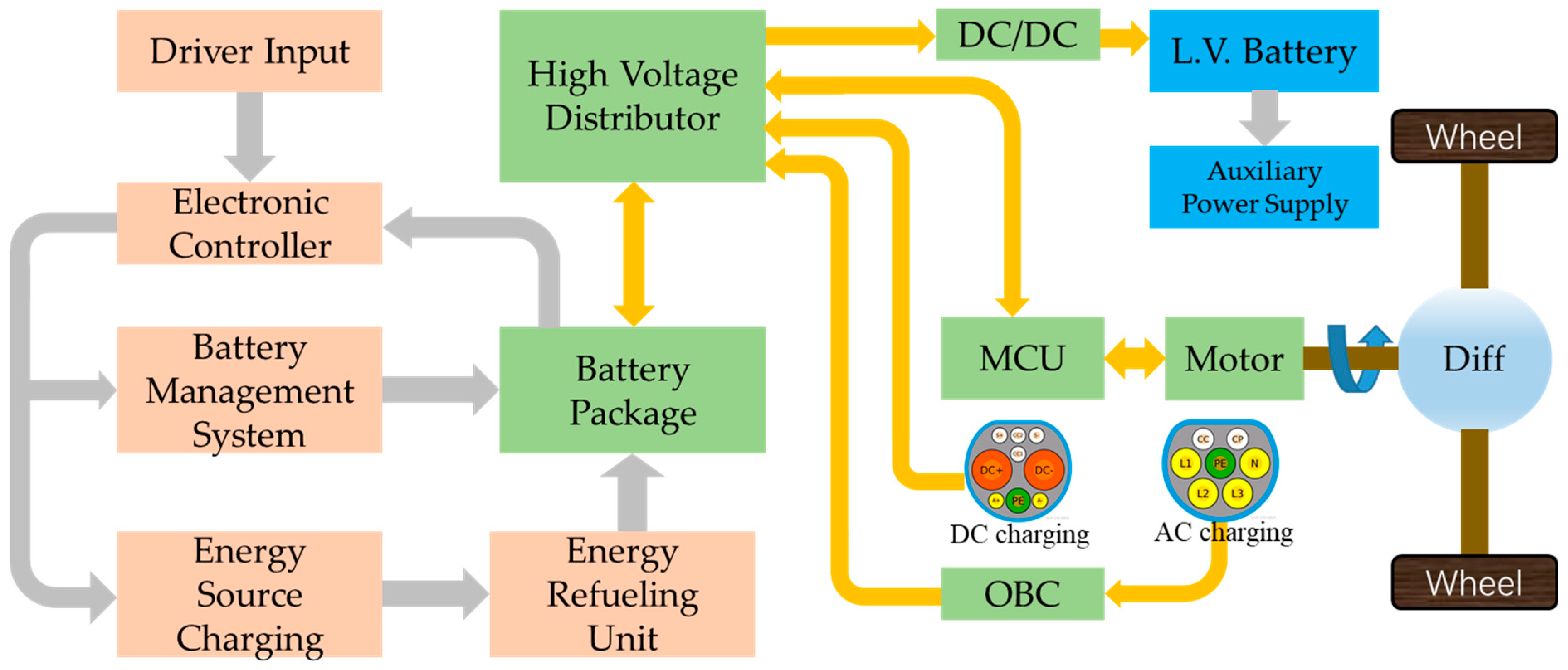
The drive structure of an EWL can be referred to as the structure of an electric road vehicle [
13]. As shown in
Figure 1, a pure electric drive vehicle structure is mainly powered by the power battery, and it is driven by the electric motor through a variable speed gearbox, differential drive axles, and half shafts to realize the transmission of torque and speed to the drive wheels. As far as the arrangement of motor drives is concerned, the types that are being researched include single-motor drive [
14], simultaneous drive with dual motors [
15], dual-motor drive with all 4 wheels [
16], hub motor drive [
17], etc. In terms of applications, single-motor drives with fixed reduction ratios are the most widely used in electric vehicles due to the simplicity and ease of control of the single-motor drive system. This reduces the production costs of electric vehicles and facilitates maintenance [
18]. In order to improve the efficiency and performance of electric drives, researchers have made improvements to the drive structure of single-motor drives, such as utilizing automated manual transmission (AMT) [
19,
20], two-speed automatic transmission (AT) [
21,
22], continuously variable transmission (CVT), and dual-clutch transmission (DCT) [
23,
24,
25]. However, the use of a single motor does not allow the vehicle to operate in the economic speed zone of the motor for long periods of time, which is detrimental to increasing the range of the vehicle. Therefore, research into multi-motor drive structures is also considered necessary to address this issue. Wang, Y. et al. [
26] presented a new two-motor hybrid drive system with two power sources, as shown in
Figure 2. The system achieves torque–speed coupling between the two power sources, greatly increasing the high-performance operating range of the motors. At the same time, a CVT is implemented to effectively increase the driving range. Holdstock, T. et al. [
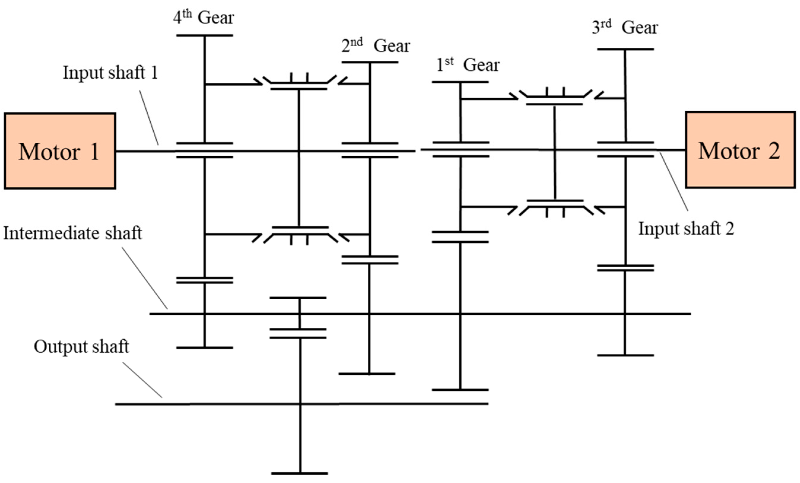
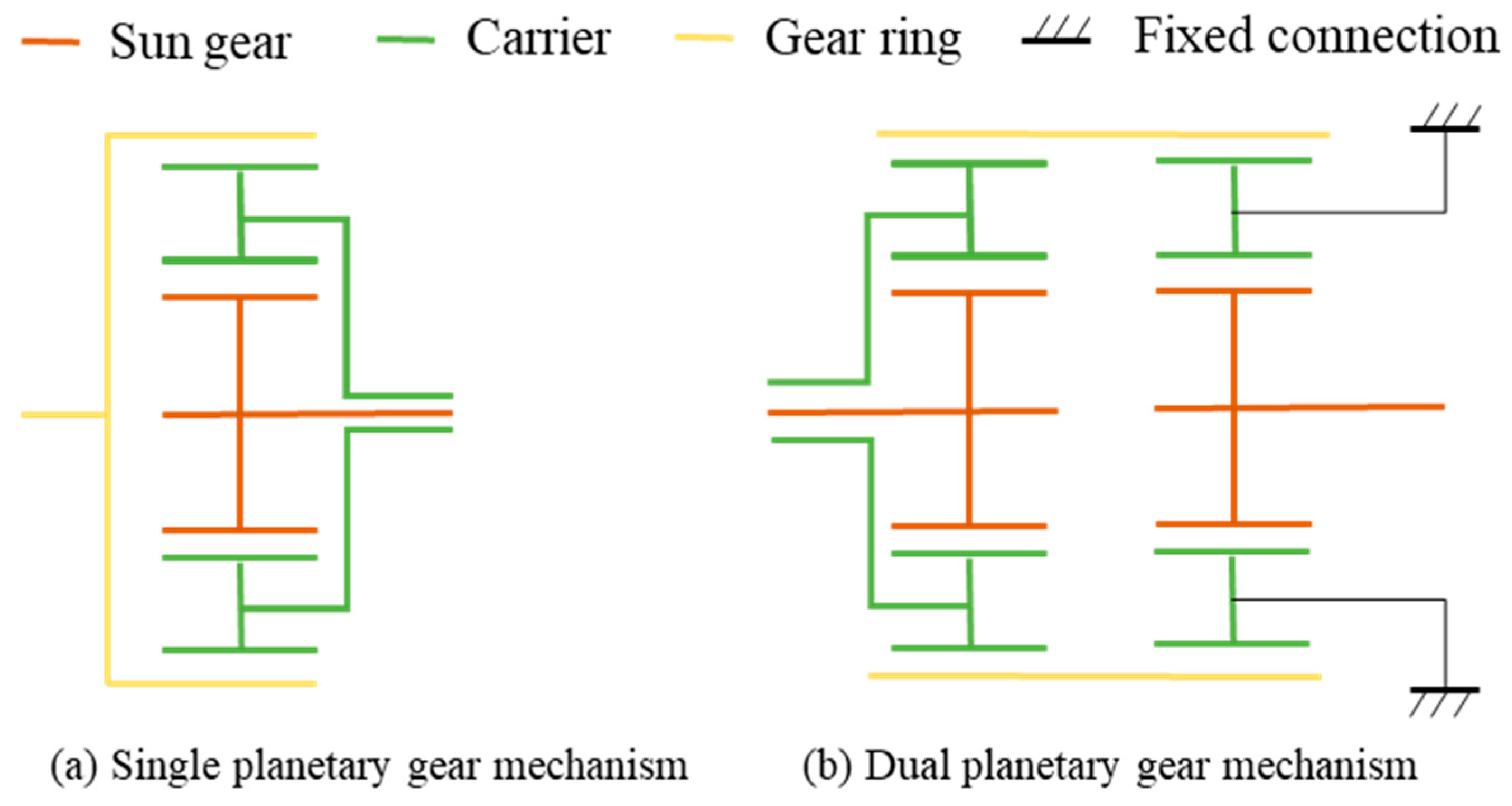
27] designed a two-motor, four-speed electric drive architecture, as shown in
Figure 3. This drivetrain architecture improves the flexibility of the motor operating points. The results of the study show that under the ECE-15 operating conditions test, the drive efficiency of the single-row planetary gear structure increased by 9.1%, and the energy recovery efficiency increased by 9.7%. Additionally, the drive efficiency of the double planetary gear structure increased by 10.9%, and the energy recovery efficiency increased by 11.1%. Mantriota, G. et al. [
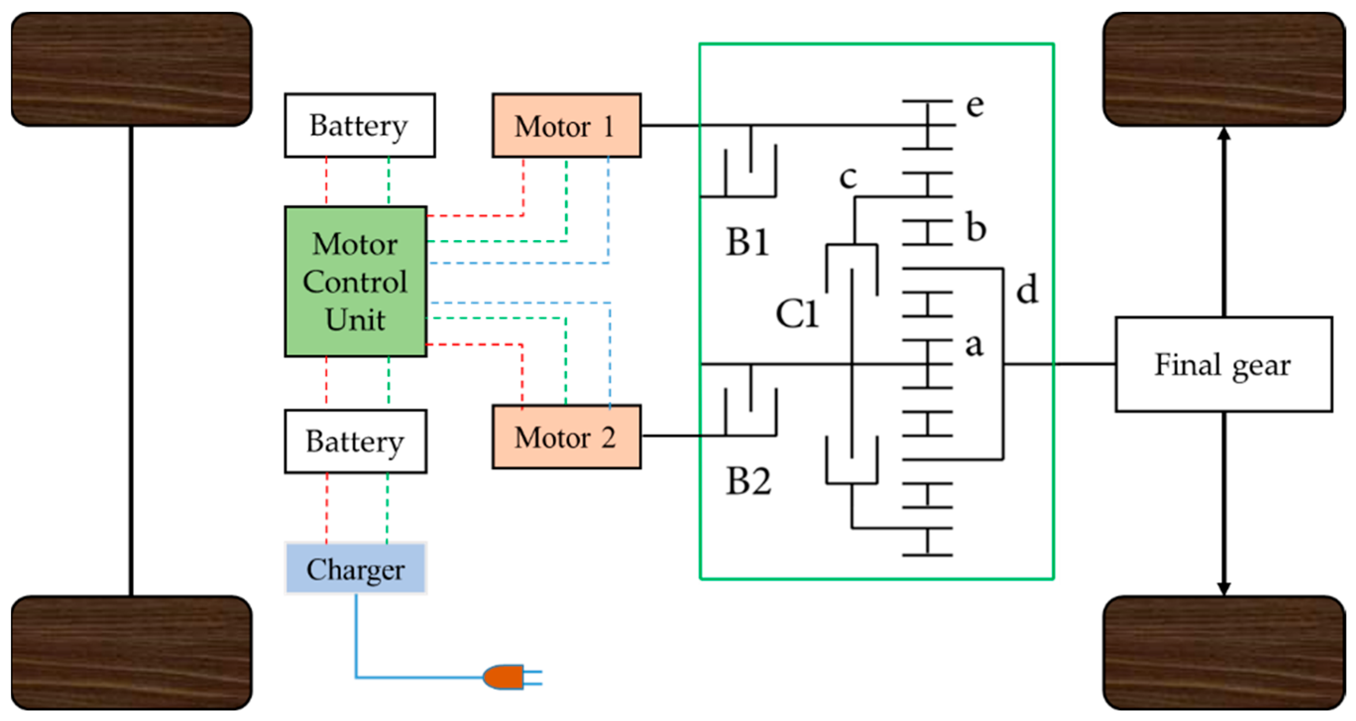
28] proposed a scheme to drive the vehicle with two smaller motors through a planetary gear mechanism, as shown in
Figure 4. The simulation results show that this dual-motor power transmission is usually better than that of a single motor, with an improvement of about 9% in both the drive efficiency and energy recovery efficiency.
Additionally, Xu, S. et al. [
29] put forward a multi-mode drive optimization control strategy based on a hierarchical control architecture to investigate the economy and dynamics of an electric vehicle with dual motors in the front axle and a single motor in the rear axle. The test showed a 6.45% reduction in energy consumption. A two-in-one motor drive control strategy is proposed that takes into account air-conditioning usage conditions based on factors such as motor efficiency within the two motors [
30], which do not have the same maximum power, and its simulation results show that energy savings of up to 2.2% can be achieved.
The literature discussed above highlights the advantages of using multi-motor drive methods to achieve an optimal power distribution and flexible control strategies, leading to improved dynamics and economy in electric drive vehicles. Similar considerations apply to EWLs, which also need to operate efficiently and dynamically. As a result, improving the drive structure and control strategies of EWLs has emerged as a key research topic in this field. EWL drive systems can be broadly categorized based on the number of motors, namely a single-motor drive system and a multi-motor drive system. A multi-motor drive system can further be classified as either a multi-motor independent drive system or a multi-motor coupled drive system [
31]. This study takes the multi-motor independent drive system of an EWL as the research object to compare its energy conversion efficiencies in three drive modes.
The remainder of this paper is organized as follows:
Section 2 presents an overview of the powertrain structures and characteristics of EWLs.
Section 3 introduces the experiment measurement for a dual-motor distributed drive EWL.
Section 4 provides the experimental results, and
Section 5 discusses the experimental results.
Section 6 concludes the paper.
2. The Structures and Characteristics of EWL
The working process of a WL usually consists of a four-stage cycle consisting of shoveling, delivery, unloading, and returning to the stockpile [
32]. For the EWL, the drive motor drives the vehicle during both stages of delivery and returning to the pile, which can be referred to as the running condition, where the drive motors contribute the main energy consumption of the WL. Tests have been conducted on the energy consumption of a dual-motor-driven loader in the running condition [
33]. The results indicate that during the running condition, the rolling resistance moment that needs to be overcome by the drive motor is the same, whether it is driven by the front wheels alone or by the rear wheels alone, which depends on the total mass of the WL and the rolling resistance coefficient of the road surface. In the running condition, the EWL can be driven by either a single motor or two motors.
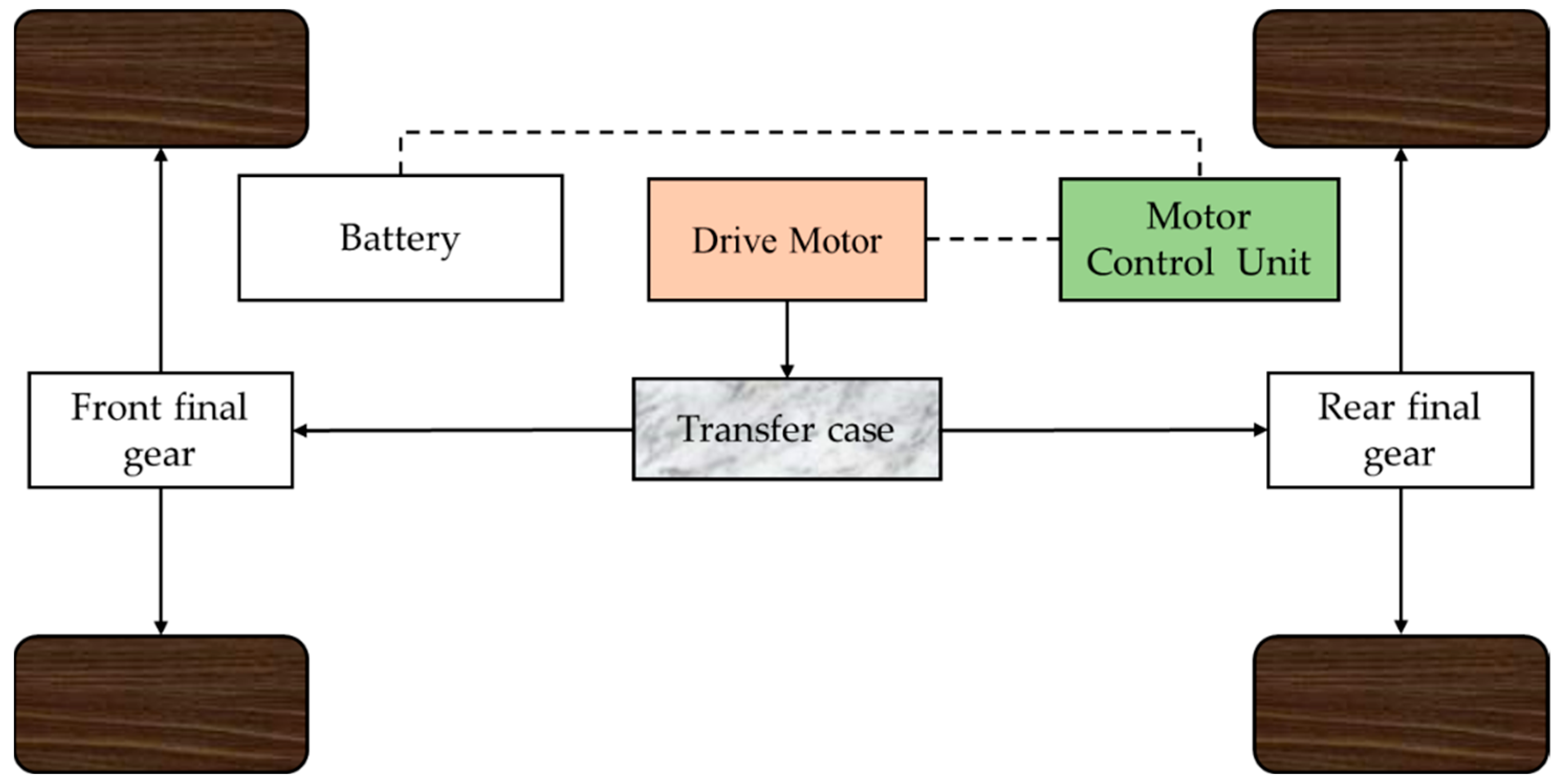
Figure 5 shows a single-motor drive powertrain, which has a similar transmission system to an engine drive except for the gearbox. In this case, a conventional diesel-driven loader is retrofitted with an electric motor in place of an engine. The motor’s speed is reduced by a reduction gear to increase the torque, which is then transferred to the front and rear axles, respectively, via a splitter box. In this configuration, the torque
generated by the front axle and the torque
generated by the rear axle and the motor torque
have to satisfy Equation (1).
where
,
, and
represent the angular velocity of the front axis, rear axis, and motor, respectively.
is the transmission efficiency of the gearbox.
The advantage of this structure is that there are fewer drive motors, and the control of the motors is simpler. However, the disadvantage is that the front and rear torques are unevenly distributed, and the simple structure of the transfer case cannot distribute the torque according to the front and rear axle torque requirements. As a result, complex transfer case structures and control algorithms need to be developed to compensate for these deficiencies [
34]. Furthermore, due to the high driving forces required for the WL’s running and shoveling conditions, motors that are capable of providing sufficiently high torque and power must be installed.
Figure 5.
Powertrain of single-motor full-drive electric wheel loader.
Figure 5.
Powertrain of single-motor full-drive electric wheel loader.
In order to solve the problem of the insufficient driving power of a single motor, dual-motor drives are widely utilized in wheel loaders [
35,
36]. A type of dual-motor drive structure of an EWL is shown in
Figure 6. The structure of the dual-motor drive for the loader involves the front and rear motors transmitting power to their respective drive axles via a reduction mechanism. Both motors are arranged longitudinally, and their output shafts are connected with a coupling, ensuring that the actual output speed of both motors remains the same at all times when driving. This allows for a power transfer between motors when one is underpowered, resulting in a combined drive. The disadvantage of this construction, however, is that the loader is prone to generating parasitic power. The relevant parameters for each motor and the corresponding drive wheel should satisfy Equation (2) in order to avoid the generation of parasitic power.
where
represents the angular speed of the front motor rotor,
represents the angular speed of the front motor rotor,
indicates the radius of the front wheel of the EWL,
indicates the radius of the rear wheel of the EWL,
is the total transmission ratio from the front motor to the front wheel drive train, and
is the total transmission ratio from the front motor to the rear wheel drive train.
Figure 7 illustrates a distributed drive configuration where one motor drives the front wheels and the other motor drives the rear wheels. The advantage of this drive configuration is that the motors can be configured according to the size and structure of the wheel loader, and each motor can be controlled by its corresponding motor controller for the output speed and torque. Additionally, this configuration allows the motors to operate at different speeds simultaneously, reducing the parasitic power generated by inconsistent front and rear wheel speeds found in the former two configurations [
37]. This structure also allows for separate front and rear motor drives. Under running conditions, the rolling resistance that needs to be overcome when the front and rear motors are driven at a constant speed can be expressed by Equations (3) and (4), respectively.
where
is the torque of the front motor,
is the torque of the rear motor,
is the total mass of the EWL,
is the coefficient of rolling resistance between the tire and the road surface,
is the angle of the slope of the road on which the EWL is travelling,
is the coefficient of air resistance of the EWL,
is the windward area of the EWL,
is the travel speed of the EWL,
is the total transmission efficiency of the front motor to the front wheel drive train, and
is the total transmission efficiency of the rear motor to the rear wheel drive train.
When the loader is working at the first stage [
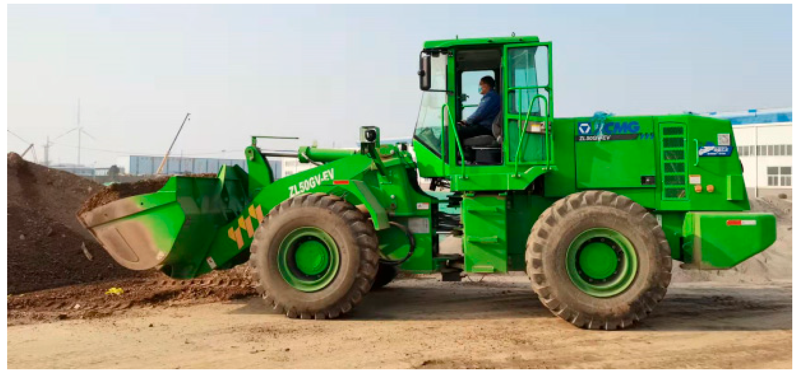
32], the operator uses the maneuvering mechanism to drop the bucket to the ground in preparation for shoveling. However, the operator may not be able to accurately sense the position of the bucket, which can cause the bucket to drop too much, leading to the lifting of the front wheels. This, in turn, can result in insufficient pressure on the ground and reduced traction. Taking into account this driving characteristic of the loader, this study utilizes the EWL configuration shown in
Figure 7 for testing. This study conducts bulldozing tests in single front drive, single rear drive, and dual drive modes to investigate which drive mode is the most economical.
5. Discussion
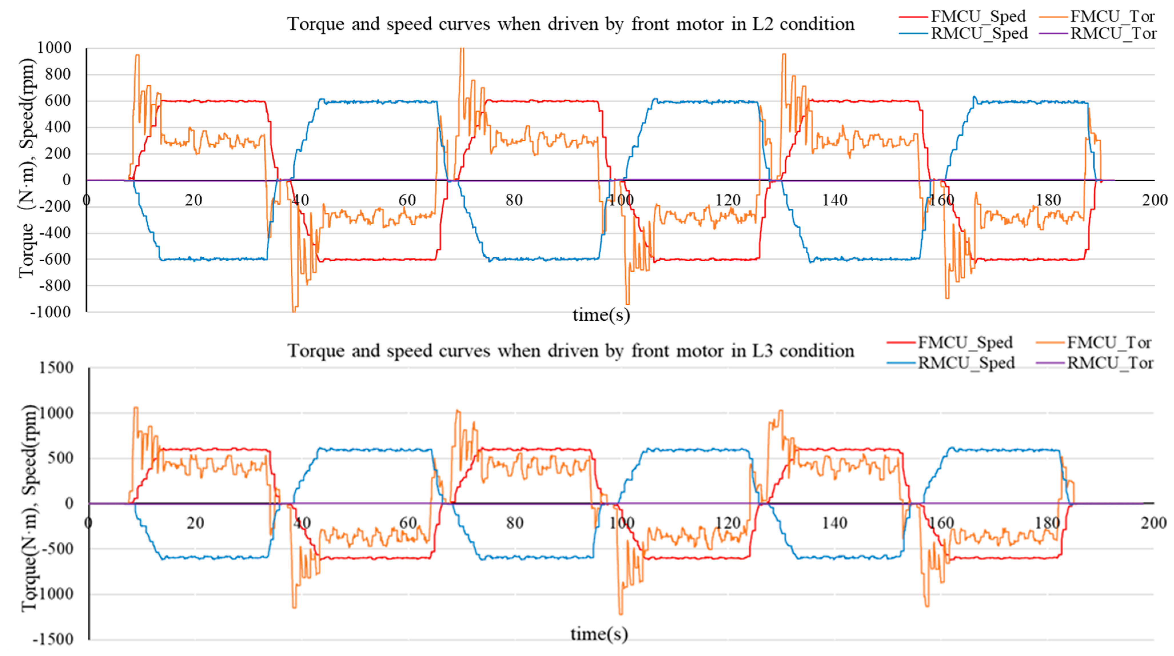
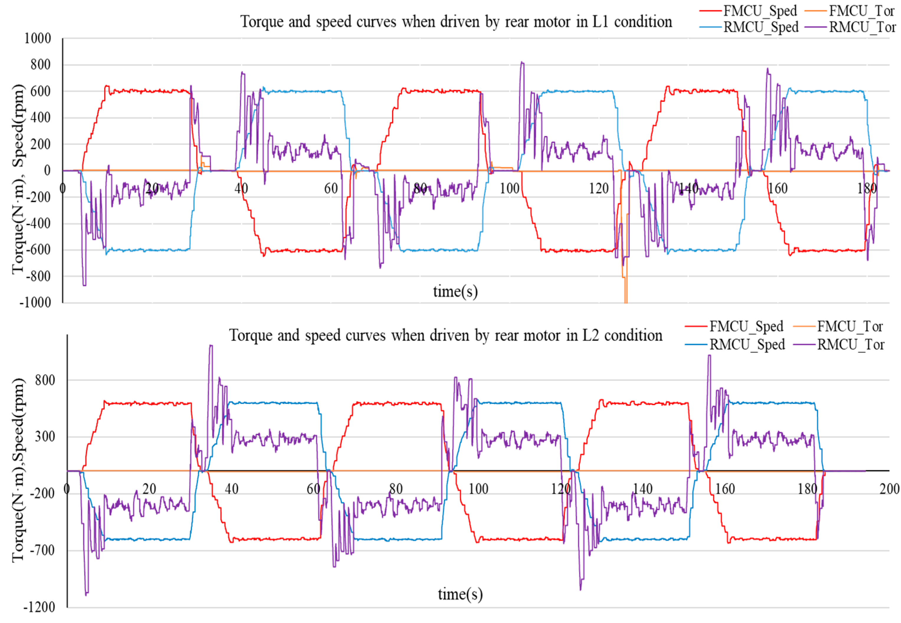
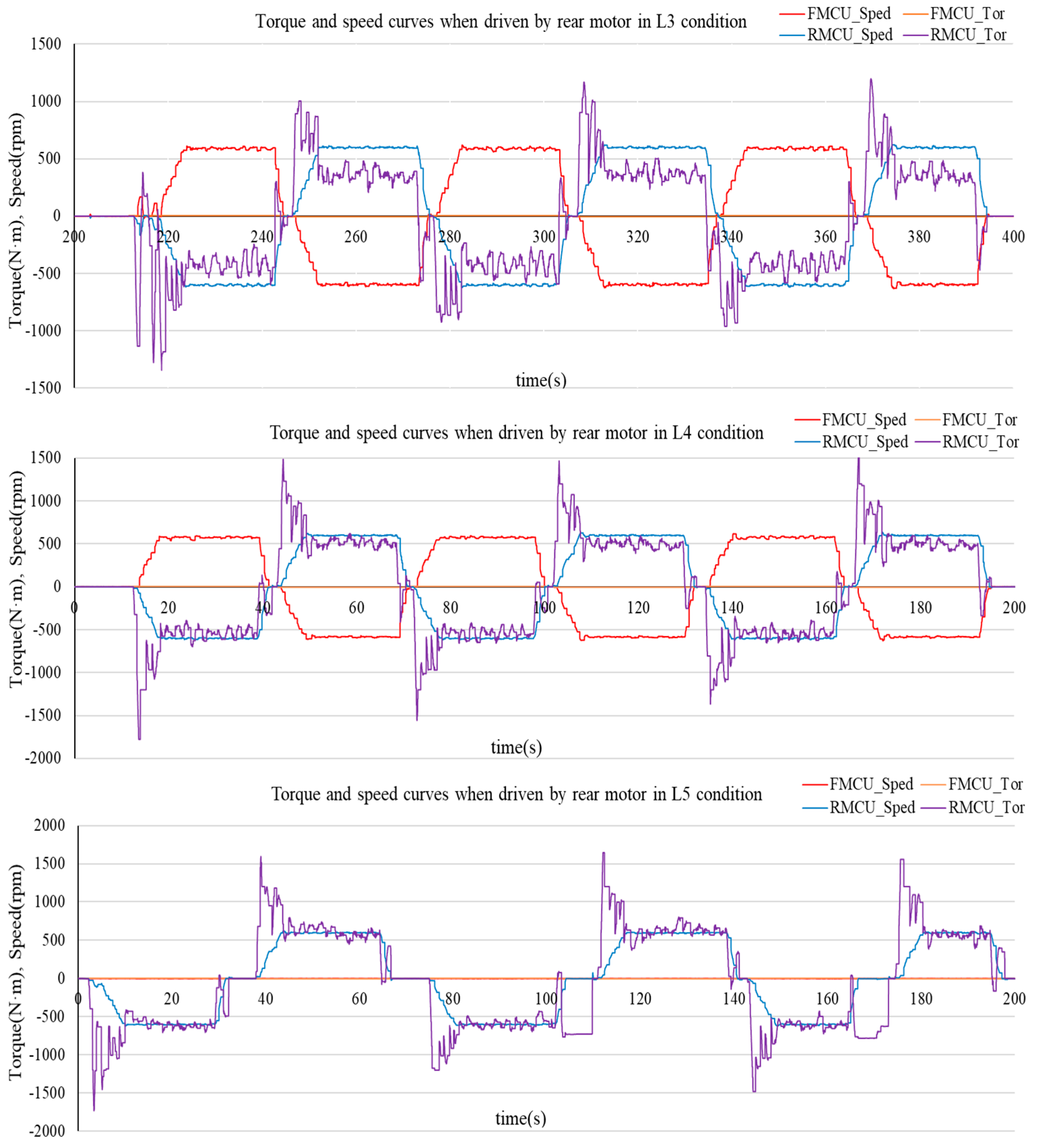
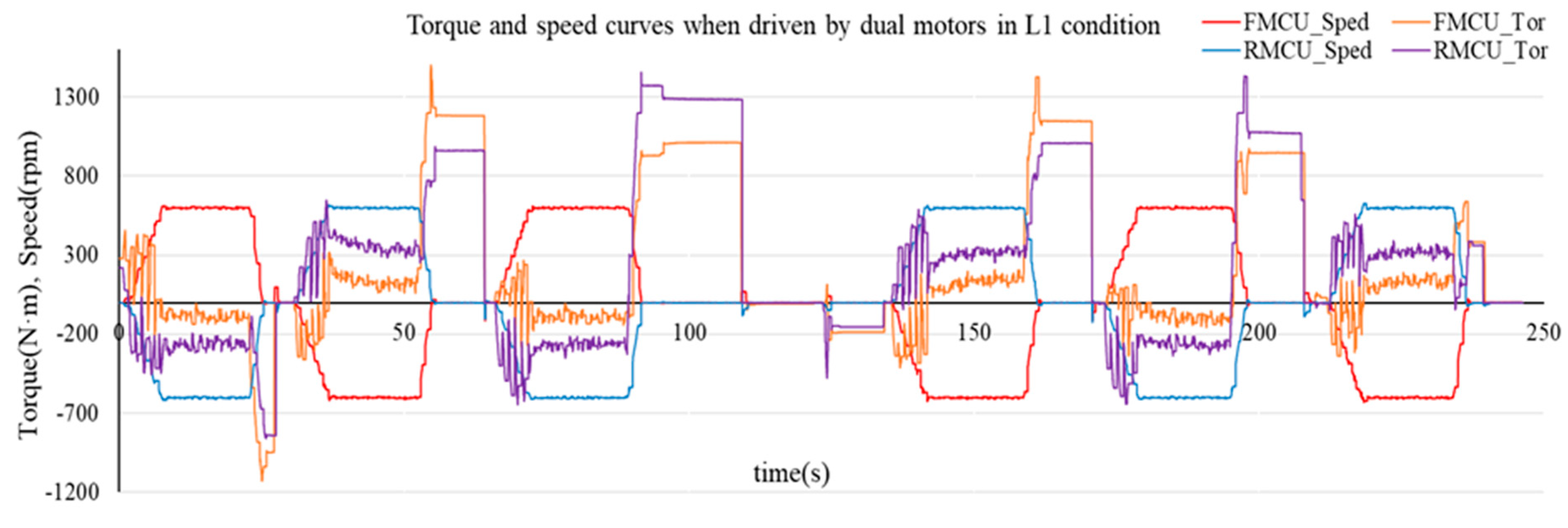
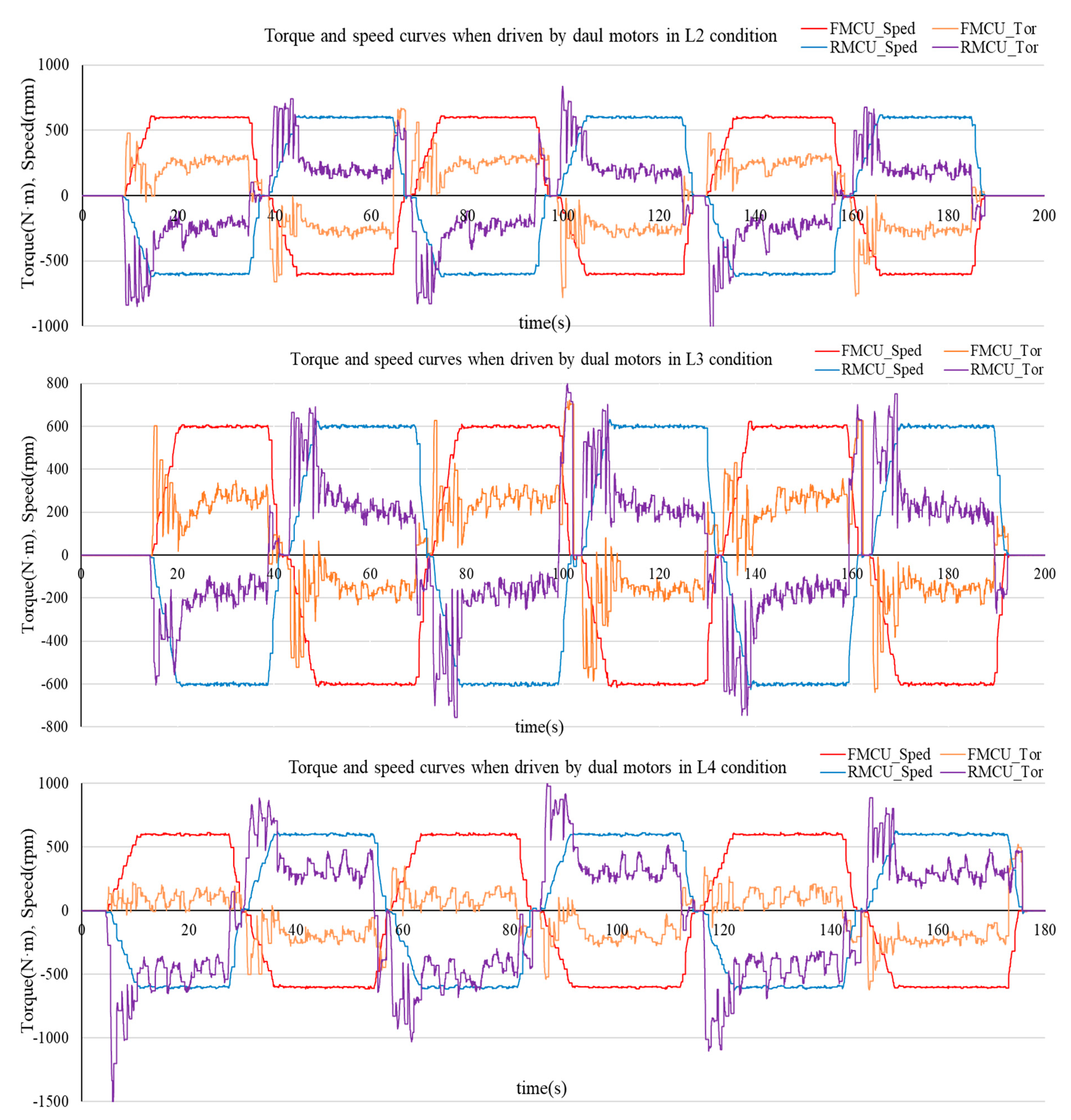
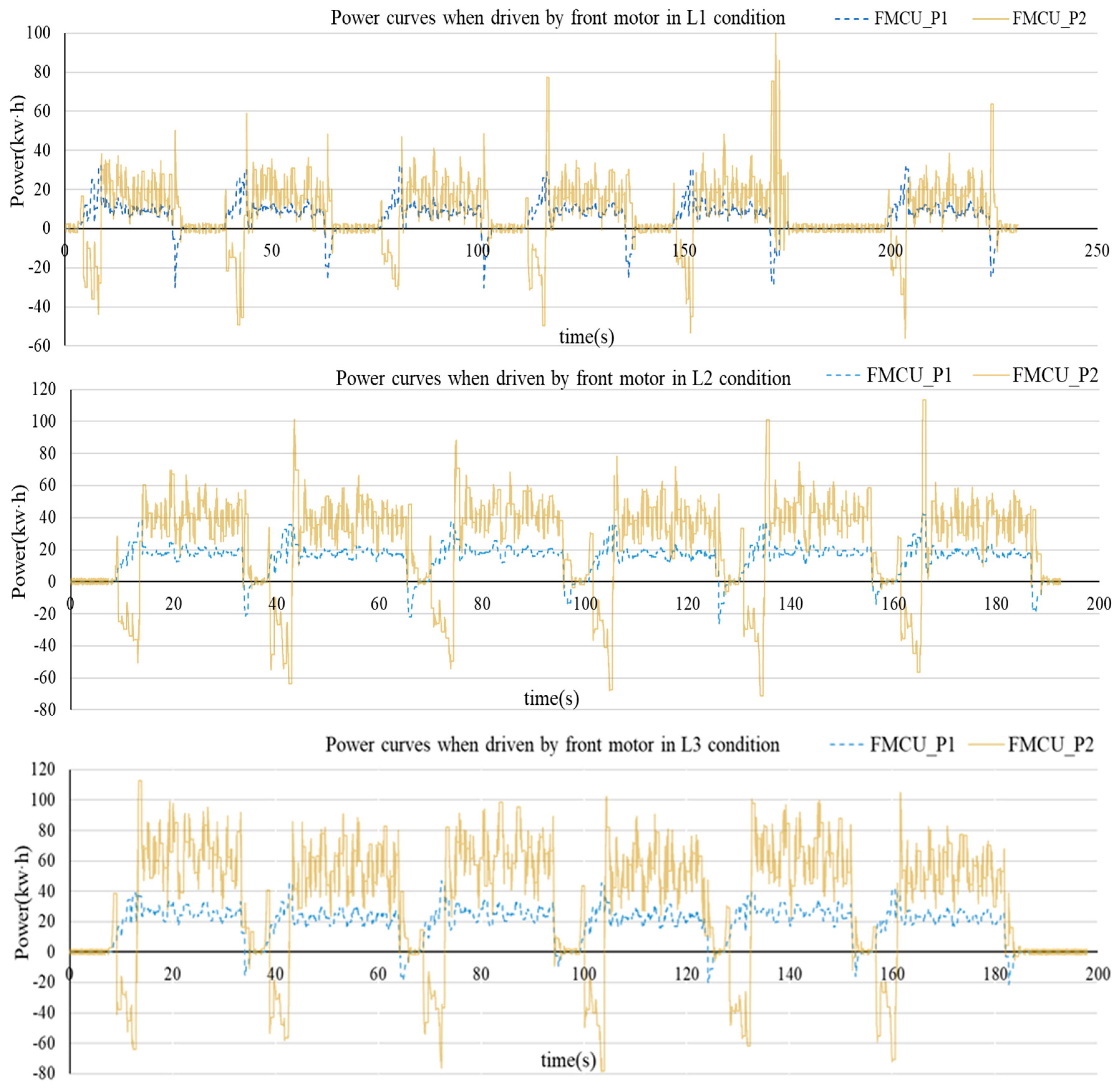
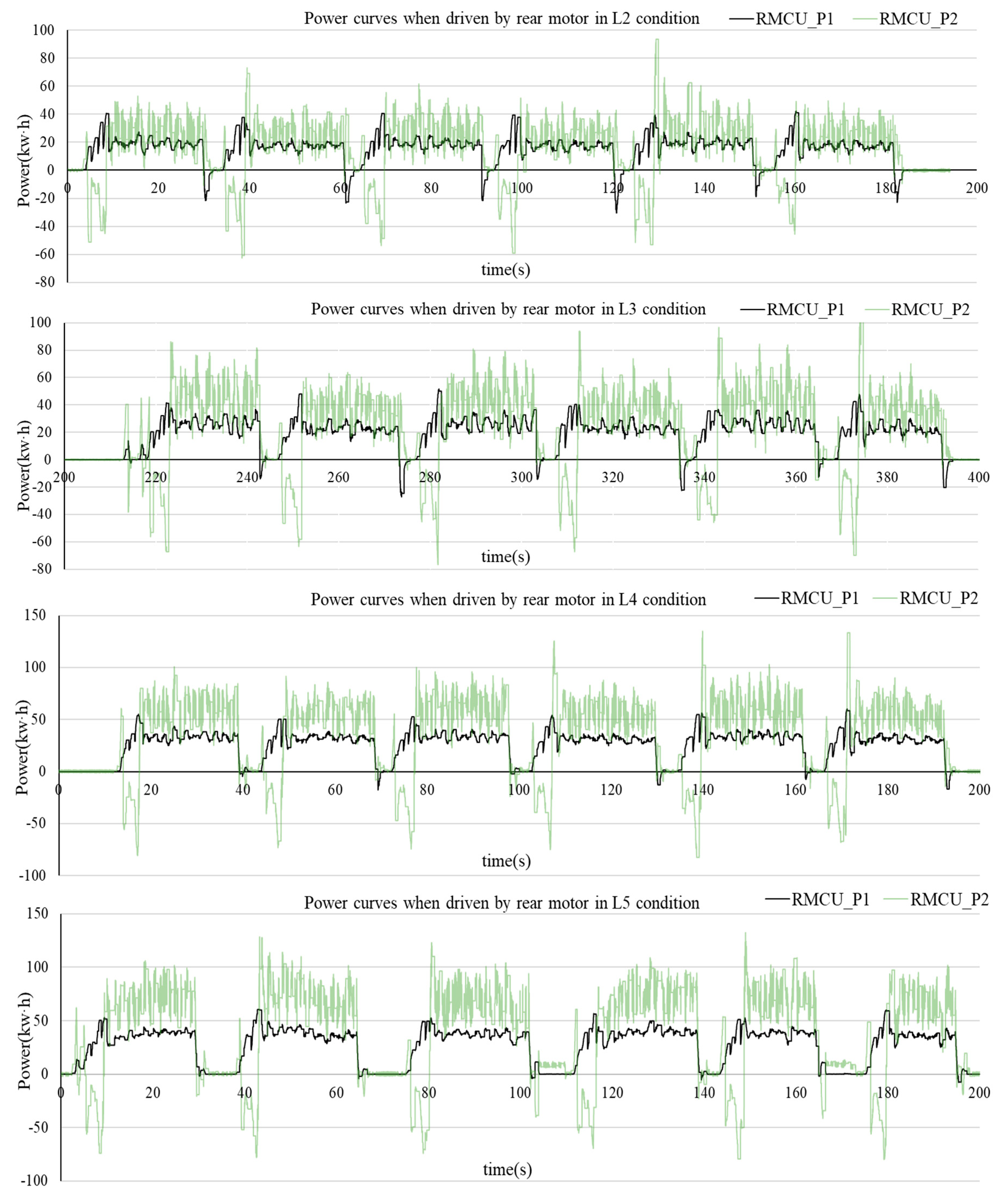
Due to the target speed control mode being selected in the test, the acceleration and deceleration phrases are not considered in this research. The data for the analysis are taken from
Figure 11,
Figure 12,
Figure 13,
Figure 14,
Figure 15 and
Figure 16 when the motors reach the target speed. The torque of the motor, the output power
of the motor, and the input power
of the motor in the data segment, showing that the torques’ variations are relatively smooth, were selected for the analysis. In the following tables,
represents the mean value of torque generated by the rear motor,
represents the mean value of output power of the rear motor, and
represents the mean value of input power of the rear motor, while
represents the energy conversion efficiency of the rear motor in the corresponding data segment. Similarly,
,
,
, and
refer to the average torque, the output power, the input power, and the energy conversion efficiency of the front motor, respectively.
indicates the sum average torque of the front and the rear motors. The energy conversion efficiency of the motor can be calculated using Formula (11).
where
in the subscript indicates the position of either the front motor by F or the rear motor by R.
The related data calculated in different cases when the EWL was driven by the front motor are listed in
Table 4. The maximum motor efficiency is 52.3% in a forward state and 54.39% in a backward state. Though the F-mode operations have not been realized in the L4 and L5 cases, the data in the three groups of L1, L2, and L3 from
Table 4 still illustrate the same pattern of change, as drawn from
Table 5.
The related data calculated in different cases when the EWL was driven by the rear motor are listed in
Table 5. They show that the energy conversion efficiency of the motor reaches up to 85.43% during the first forward-moving period in the L1 case and the top efficiency is 86.02% during the forward-moving periods in cases L1 to L5. The minimum energy conversion efficiency of the motor is 51.87% in the forward-moving periods, while the lowest is 52.74% in the backward-moving periods. Of all the values of the average torque, the positive values occur in the forward operations and the negative values occur in the backward operations. From L1 to L5, the absolute values of the average torque, average input power, and average output power increase consistently in general, while the opposite is true for the energy conversion efficiency of the motors.
The related data calculated in different cases when the EWL was driven by the two motors are listed in
Table 6. The necessary parameters of the D-drive mode are the average torque of the motors, the overall energy conversion efficiency of the motors, and the sum torque of the two motors. In the data processing, the sum of the torques of the motors are converted into positive values for the depiction of the curves. The total efficiency of the twin motors is calculated using Equation (12).
Figure 17 displays the average values of the motor torque, input power, output power, and efficiency in F-drive mode from condition L1 to condition L3.
Figure 18 presents the average values of the motor torque, input power, output power, and efficiency in D-drive mode from condition L1 to condition L5.
The orange curves represent the change in the motor output power, the blue curves show the change in the motor input power, the red curves show the change in the average torque, and the green curves show the change in the motor efficiency. The diagram includes eight curves in both
Figure 17 and
Figure 18, in which the solid lines indicate the curves for each parameter when the EWL is moving forward, while the dashed lines indicate the curves for each parameter when the EWL is moving backward.
As shown in
Figure 17, the average torque, average input power, and average output power of the motor in the forward state of the EWL are the smallest in the L1 condition and the largest in the L3 condition. It can be drawn by the change in torque that the resistance rises as the vertical force between the bucket and the ground increases. The energy conversion efficiency of the motor is 50.80% in the L1 condition, 43.75% in the L2 condition, and 40.39% in the L3 condition, indicating that the energy conversion efficiency of the motor decreases as the front wheels of the loader are lifted more. This pattern is consistent for both the forward and backward movements of the EWL.
Figure 17.
Curves of motor power, motor efficiency, and motor torque in F-drive mode.
Figure 17.
Curves of motor power, motor efficiency, and motor torque in F-drive mode.
As shown in
Figure 18, the average torque, average input power, and average output power of the motor in the forward state of the EWL are the smallest in the L1 condition and the largest in the L5 condition, and all show a gradual increasing trend. The energy conversion efficiency of the motor is 82.62% in the L1 condition, 64.96% in the L2 condition, 58.40% in the L3 condition, 56.03% in the L4 condition, and 52.99% in the L5 condition, indicating a same pattern of change as that in the F-drive mode. The difference is that the motor efficiency is higher in all operating conditions corresponding to the R-drive mode compared to the F-drive mode.
Figure 18.
Curves of motor power, motor efficiency, and motor torque in R-drive mode.
Figure 18.
Curves of motor power, motor efficiency, and motor torque in R-drive mode.
Figure 19 shows the curve of the variation in the average value of the total motor torque and overall motor energy conversion efficiency from the L1 to L4 operating conditions in the D-drive mode. Shown in purple is the curve of the change in the sum of the torque of the two motors, and shown in green is the curve of the change in the overall motor efficiency.
Figure 19 indicates that in the D-drive mode, the sum of the motor torques tends to rise with the increasing bucket ground pressure, whether the EWL is driving forward or backward. When driving forward, the total torque is 174.59 Nm at the L1 condition and 577.7 Nm at the L4 condition, while the energy conversion efficiency is 40.05% at the L1 condition and 82.67% at the L4 condition, which also show an increasing trend. The same pattern of change is observed in reverse. Compared to the F-drive and D-drive modes, this shows that the overall efficiency achieved with the dual-motor drive is higher when the EWL requires more torque.
Figure 19.
Curves of total motor torque in D-drive mode.
Figure 19.
Curves of total motor torque in D-drive mode.
Based on the analysis above, we can derive a trend table illustrating the changes in the motor torque and motor energy usage efficiency as the height of the front wheel lifting increases, as shown in
Table 7.
Based on the discussion above, a proposal for the motor energy improvement of dual-motor drive EWLs is put forward below, which may provide researchers and manufactures with a potential solution.
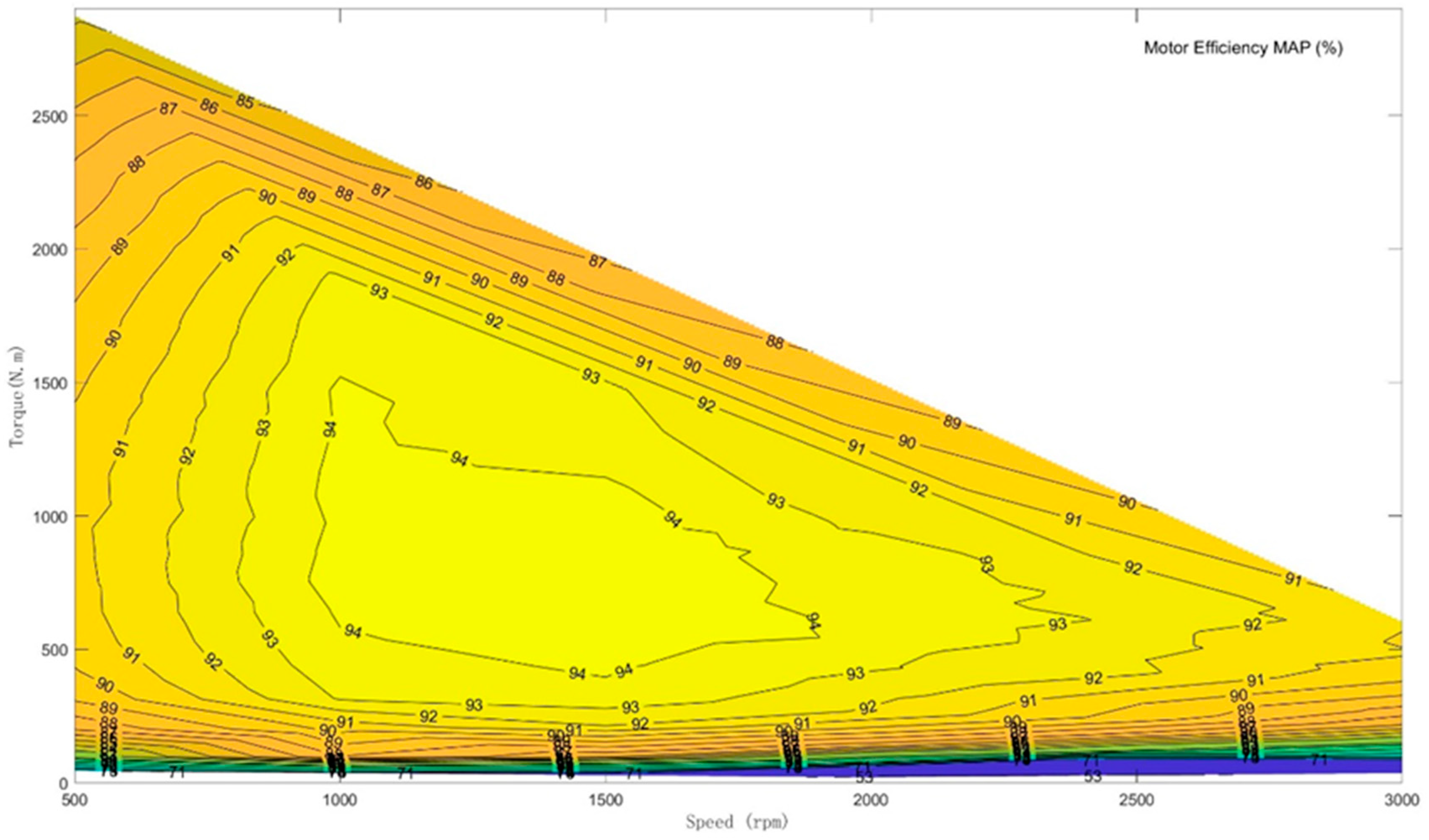
For a two-motor drive EWL, the front wheel can be driven by a smaller motor, while the rear wheel can be driven by a lager one in torque and power. In the running state of shoveling work, the rear motor can be the primary drive motor. When the bucket is lowered towards the ground for the preparation of the shoveling material, this will cause an increase in the pressure on the rear wheel. If the drive force of the rear motor is not enough, the front motor will be activated by the MCU to generate enough toque together with the rear motor. However, this should have a limited condition, that is, the rear motor should work on the high efficiency range as much as possible according to the energy efficiency MAPs of the two motors derived by the tests. In addition, elevating the front wheels to a certain extent can induce tire slippage. When the grip between the front wheels and the ground diminishes, a portion of the energy from the driving force is diverted into parasitic power, an undesirable occurrence. This can be identified by monitoring whether the front wheel rotation speed suddenly exceeds that of the rear wheels. Detecting the tire slip trigger control of the hydraulic circuit governing the bucket or boom allows for adjustments to be made to the bucket’s position and, consequently, allows for traction to be restored between the front wheels and the ground. Employing these methods can effectively reduce energy wastage during loader operations. It is worth noting that various other factors, including the road conditions, terrain, temperature, weather, material properties, and driver behavior, also play roles. These aspects can be considered in future research endeavors aimed at achieving intelligent assisted driving for loaders.
