Article

Design and Application of the unIT-e2 Project Use Case Methodology

by
Adrian Ostermann
1,2,*,
Patrick Vollmuth
1,2 and
Valerie Ziemsky
1
1
FfE Munich, 80995 München, Germany
2
School of Engineering and Design, Technical University of Munich (TUM), 80333 München, Germany
*
Author to whom correspondence should be addressed.
World Electr. Veh. J. 2023, 14(1), 13; https://doi.org/10.3390/wevj14010013
Submission received: 1 November 2022 / Revised: 16 December 2022 / Accepted: 3 January 2023 / Published: 5 January 2023

Abstract

:
The ramp-up of electromobility requires cross-industry holistic solutions. However, bringing together stakeholders from different branches holds challenges. One prerequisite for successful collaboration is a uniform understanding of roles, processes, and interfaces. Based on existing methods and experience from former projects, this paper describes a method for the systematic description of use cases for smart charging of electric vehicles. This method enables a uniform understanding of all actors involved and guarantees application-oriented usability. The unIT-e2 use case methodology consists of the business-use case level and the technical-use case level, which describe the use case in a structured layout. The method was applied in all so-called clusters of project unIT-e2. In total, we identify 25 higher-level business use cases and highlight similarities and differences between them. Further, this paper describes the business-use case regulatory-defined grid-serving flexibility in detail.

1. Introduction

The European Union (EU) aims to reach climate neutrality by 2050 to meet the goal of the Paris Agreement to limit global warming to well below 2, preferably to 1.5 degrees Celsius, compared to pre-industrial levels [1]. Therefore, the EU needs to reduce emissions by increasing energy efficiency and investing in green technology. The European electricity sector lowered its emissions by 39% in 2019 compared to 1990 [2]. However, even if the generation of electricity were solely renewable, it would not be sufficient to achieve the goal of climate neutrality. A high share of variable renewable energy (VRE: wind and photovoltaic—PV) results in various challenges for the energy system due to intermittency, location-specific output, uncertainty, and limits in predictability [3,4,5,6]. To ensure the security of supply, which is put at risk by the integration of high shares of renewable energies, the energy system must be flexible by shifting demand in times when renewable energy generation is high. Sector coupling is widely considered necessary to achieve flexibility, significant emission reduction, and climate neutrality by interconnecting the energy-consuming sectors of industry, buildings (heating and cooling), and transport with the energy-producing sector [7,8,9]. Especially the transport sector needs to be transformed since greenhouse gas (GHG) emissions have increased between 2013 and 2019 as opposed to the other sectors [10]. In 2018, more than 12% of EU GHG emissions were caused by passenger cars [10]. Decarbonization in the transport sector can be realized by shifting to electric vehicles (EVs) if the electricity consumed is generated from renewable energy sources [11]. EVs can further offer positive and negative flexibility by charging batteries during periods of low demand or low prices, by interrupting an ongoing charging process, or by reducing charging power. Therefore, the integration of EVs is one of the most promising means to achieve the 2030 target of the European Commission’s current revised proposal to reduce average fleet-wide emissions from newly registered vehicles from 37.5% to 55% relative to a 2021 benchmark [12]. The trend towards an increasing share of EVs can already be observed in the EU. In 2019, the share of newly registered passenger EVs (battery electric vehicles—BEV—and plug-in hybrid electric vehicles—PHEV) in the EU was 3% [13]. In 2020, this share increased to 11%, and in 2021, to 18% [13].
The growing prevalence of EVs results in new business opportunities opening the market for new players: original equipment manufacturers (OEM), such as VW or Tesla, are now offering electricity tariffs in Germany [14,15]. On the one hand, the electrification of components in the transport sector, like EVs, or in the heating sector, such as heat pumps (HP), offers new opportunities and flexibility. On the other hand, electrification leads to increasing grid loads entailing new challenges for grid operators. In Germany, electric vehicle supply equipment (EVSE) with an output of 3.7 to 11 kW must be registered with the grid operator according to section 19 of the Low-Voltage Connection Ordinance (German: Niederspannungsanschlussverordnung—NAV) [16]. The installation of EVSE above 11 kW even requires a permit from the grid operator. Besides their permission to curtail VRE, grid operators might be authorized to interrupt charging sessions to ensure grid stability in the future. This, however, is in contradiction to EV user needs for the highest availability of mobility. Potential grid operator interventions could also affect other players’ economic interests, such as flexibility aggregators. Therefore, all market participations must have a coordinated approach to reconcile grid stability, high shares of renewable energy, and customer satisfaction with diverse business models of other parties. This challenge is the starting point of the project unIT-e2, which unites the automotive and energy sector to enable the integration of electromobility in line with grid and market requirements by defining uniform processes and creating standardized interfaces.

2. The Project unIT-e2, German Market and Regulations

By bringing together 29 partners from the automotive and energy sector, IT and charging infrastructure, and the scientific research sector, the project unIT-e2 offers a unique consortium along the entire value chain [17]. The project started in August 2021 and will last three years with the research institute FfE as the consortium leader. The project focuses on the market and grid integration of electromobility by defining interoperable, holistic, and intelligent charging concepts and demonstrating them in four large-scale field trials defined as clusters. These clusters are named Cit-E-Life, sun-E, Harmon-E, and Heav-E. Each cluster consists of an automobile manufacturer and various partners from the energy and IT sector. Accompanying the four clusters, three conceptional subprojects (SP) ensure the transfer into practice: SP research, SP grid, and SP project management and synthesis. At the beginning of the project, it was necessary to identify and define use cases that the clusters will demonstrate. For the successful demonstration in field trials, all parties involved must have the same understanding of the procedures and processes that arise from the electromobility use cases. Due to the high number of partners, the structure of different clusters, and the various individual backgrounds, FfE developed the unIT-e2 use-case methodology to define and describe the use cases systematically and uniformly.
Integrating electromobility into the energy system requires a fitting regulatory environment, which must be well-known and taken into consideration during the process of use-case development. German legislation aims to induce flexibility procurement with several incentive mechanisms. According to § 41a Energy Industry Act (German: Energiewirtschaftsgesetz—EnWG), electricity suppliers are required to offer variable tariffs to their customers to incentivize energy savings or control consumption [18]. Furthermore, § 41a (2) EnWG obliges electricity suppliers with a certain size of their customer base to offer electricity supply contracts with dynamic tariffs in the future [18]. Time-variable tariffs aim to incentivize shifting electricity consumption to times of low electricity stock exchange prices, usually correlating with a high share of renewable electricity generation. Similar to financial incentives on the actual electricity price, German legislators established a measure to enable variable grid fees. § 14a EnWG requires grid operators to offer reduced grid fees for consumers providing the grid-serving control of their controllable consumption devices [18]. However, in September 2021, the European Court of Justice found § 14a EnWG not to comply with European law (C-718/18) [19]. The only institution allowed to develop grid fee models is the Federal Network Agency. Thus, the concrete handling of variable grid fees in Germany remains unclear. In this respect, the reform of the § 14a EnWG failed after more than two years of consultation. The draft, which was withdrawn by the Federal Ministry for Economic Affairs and Climate Action (German: Bundesministerium für Wirtschaft und Klimaschutz—BMWK, formerly BMWi) in January 2021, would have allowed grid operators to reduce the power of “controllable consumer devices”, such as EVSE, or even disconnect them from the grid if risking grid congestion otherwise [20]. While the energy sector broadly supported the policy that was originally planned, there was growing concern in the automotive sector that this would hinder the progress of electromobility and cause irritation among customers. The reform of §14a EnWG is the task of the current federal government. One of the project goals of unIT-e2 is to develop cross-sectoral accepted criteria for the redesign of §14a EnWG and to communicate them to the political decision-makers.
At the same time, the compulsory smart-meter rollout (§29 German Federal Law on Metering Point Operation, German: Messstellenbetriebsgesetz—MsbG) further complicates flexibility procurement. Accordingly, energy generation plants with a minimum installed capacity of 7 kW and consumers with an annual consumption exceeding 6000 kWh are subject to the mandatory installation of a smart metering system consisting of a modern metering device and a smart meter gateway (SMGW) [21]. While modern metering devices measure the actual electricity consumption, SMGWs serve as a communication interface to process, save, and communicate measured data. The state-of-the-art smart-metering-device technology is insufficient for a widespread rollout, as not all kinds of tariffs can be measured, e.g., load-based variable tariffs, consumption-based variable tariffs, and critical peak pricing, including real-time pricing [22]. Therefore, the Federal Cyber Security Authority (German: Bundesamt für Sicherheit in der Informationstechnik—BSI) set up a stage model for the further development of standards for the digitalization of the energy transition [23]. The stage model describes the necessary smart metering system development path to enable use cases around submetering, electromobility, and control of flexibilities. As the smart meter rollout affects consumers with an annual electricity consumption higher than 6000 kWh, most common households are currently not affected by the smart meter rollout. However, by adding the charge load of an electric vehicle to the standard household load, the expected annual electricity consumption increases by 3000 kWh, thus requiring a smart metering device [24,25]. The project unIT-e2 addresses the described regulatory challenges: usage of variable electricity tariffs for charging EVs, control of flexibilities, the concrete design of variable grid fees, and whatever else is necessary.

3. unIT-e2 Use-Case Methodology

In the field of electromobility, actors with different roles must work together, such as distribution-grid operators, transmission-grid operators, charge-point operators, metering-point operators, energy suppliers, and aggregators. Each actor knows his area of expertise and the associated processes. For the successful and well-ordered execution of an implementation project, the uniform comprehension of all processes and interfaces up to a certain level of detail is indispensable. This is where the use-case methodology developed in the unIT-e2 project can be applied. Starting with the fundamental understanding that a use-case definition is necessary for joint implementation, the objective of the methodology is a systematic description of use cases based on a uniform level of detail, which ensures a consistent understanding of the use-case processes by all participants.

3.1. Literature Review

In literature, different use-case definitions can be found [26,27]. Cockburn defines a use case as “a description of the possible sequences of interactions between the system under discussion and its external actors, related to a particular goal” [26]. At the same time, ref [27] depicts a use case as a set of actions carried out by a system and produces an observable result that is typical of value for one or more actors or other stakeholders of the system. The second definition is closer to our understanding of use cases than the first one. Therefore, we define a use case as follows:
“A use case describes the functionality of a system from the user’s point of view. A user can be a person, a role, an organization, or another system. The name of the use case is derived from the goal of the use case from the user’s point of view. The aim of defining use cases is to reach an agreement and a common understanding about the behavior and scope of a system between the stakeholders of a project. Use cases can be represented graphically or in text documents”.
Several norms and methods to develop and describe use cases exist [26,27,28,29,30,31,32]. Cockburn establishes a guide in his book Writing Effective Use Cases on how to define use cases with a consistent style [26]. The use-case diagram describes the user’s possible interactions with a system based on graphical representation via the unified modeling language (UML) and is often used in software design [28]. The aim is to mimic the real world as simply as possible to understand how the system is going to be designed. The e3-value methodology, first developed by [30], is a well-accepted business modeling technique also based on graphical representation and has been developed to be tractable and lightweight. The focus of the e3-value model lies in the exchange of objects of value between actors performing activities. Originally used in explorations of e-commerce business models, e3-value models abstract from process details, thereby helping decision-makers focus on economic viability [33]. One limitation of e3-value models is the focus on the business model, leaving out many other concerns [33]. The IEC 62559 series provides a use-case methodology for power-system professionals to specify and detail “their user requirements for automation systems, based on their utility business needs” [29,34]. The IEC 62,559 series describes processes and provides basics for the use-case methodology like terms or use-case types, while it also defines the structure of a use-case template, an actor list, and a list of requirements. Further, it defines the required core concepts and their serialization into an XML format of a use-case template [29]. The IEC 62,913 series builds on the use-case methodology defined in the IEC 62,559 series and gives a more detailed methodology for describing use cases and extracting requirements from them, focusing on smart grids instead of only power systems [27]. The IEC 62,913 series focuses on capturing and sharing generic smart-grid requirements from a basis for standardization work that ensures and improves the interoperability between smart-energy systems and components [27]. However, for non-domain experts, the benefit of the documents is rather limited. Further, the familiarization and the consistent, correct use of the documents are time-consuming. The smart-grid architecture model (SGAM) defined by [35] provides technology-neutral analysis and the architectural or cross-system mapping of smart grid use cases. SGAM is thus suitable for representing the technical–operational implementation of use cases and the associated interoperability requirements. IEEE defines interoperability as “the ability of two or more systems or components to exchange information and to use the information that has been exchanged” [36]. Through the different views of the smart-grid architecture, technical (syntactic), informational (semantic), and organizational (pragmatic) interoperability can be represented and checked [37]. A guide on applying SGAM can be found in [37]. The use-case methodology developed by Faller et al. [32] during the project C/sells is mainly based on [27,31]. Faller et al. defined three main steps to describe a use case: 1. description of the business use cases and the use-case concept, 2. process and system description, and 3. procedure specifications (sequence diagrams). Business-use cases (BUCs) describe the business application and specify roles and responsibilities for executing business processes, while the focus is on the company’s internal processes and not the overall system. In this process, the involved participants, relevant influences, and the purpose of the use case are clarified and presented [32]. Furthermore, [38] differentiates between parties (legal entities, i.e., either natural persons (a person) or judicial persons (organizations)), roles (representing the intended external behavior (i.e., responsibility) of a party), actors (a party that participates in a (business) transaction), and responsibilities (external behavior to be performed by parties). Role models such as [39,40,41] can be used to define roles uniformly across projects. The first step includes identifying political and regulatory factors influencing the use case by analyzing laws, directives, regulations, and standards. Afterward, the business services and processes are visualized in an e3-value model, including the identified roles, actors, parties, and responsibilities. Additionally, the business or operational benefit is described in a business-model-canvas or a platform-business-model-canvas. As the last step 1, the use-case goals are documented in a classical project-management target table. In step 2, Faller et al. focus on the representation of system components and the associated process scope when using the components in the use case [32]. Using a detailed process diagram (e.g., business process model and notation [42]), the description of initial interfaces, communication requirements, parts of the system (components), and their functions is developed in tabular form. In step 3, the use case is described in more detail (technically) about its procedures (sub-processes). For this purpose, the use case is described in sequence diagrams, and the respective information flows, messages, subsystems, and applied standards are specified in more detail.
From experience in the project C/sells, applying the described use-case methodology by Faller et al. [32] compared to other ones like [29] or [27] is less complex but still requires a considerable amount of time and resources to document every use case. In other projects, such as InDEED [43], Trade-EVs II [44], and Bidirectional Charging Management (BCM) [45] use cases, were identified with a similar or adapted use-case methodology. Experience from the aforementioned projects showed that creating, maintaining, and reading documents with long texts is time-consuming, particularly in keeping the documents up to date and consistent. Further, various partners perceived the many different visualization methods as unnecessary. Only roles and actors directly affected or involved in the use case should be displayed to enhance readability. Another lesson was that the business and technical discussions often mixed and made it challenging to achieve purposeful results during each step or phase. A stronger separation of these two fields would thus increase the efficiency of use-case development. Due to the size of unIT-e2 and a large number of partners in the four different clusters resulting in many use-case documents, an efficient method was essential.

3.2. Methodology Description

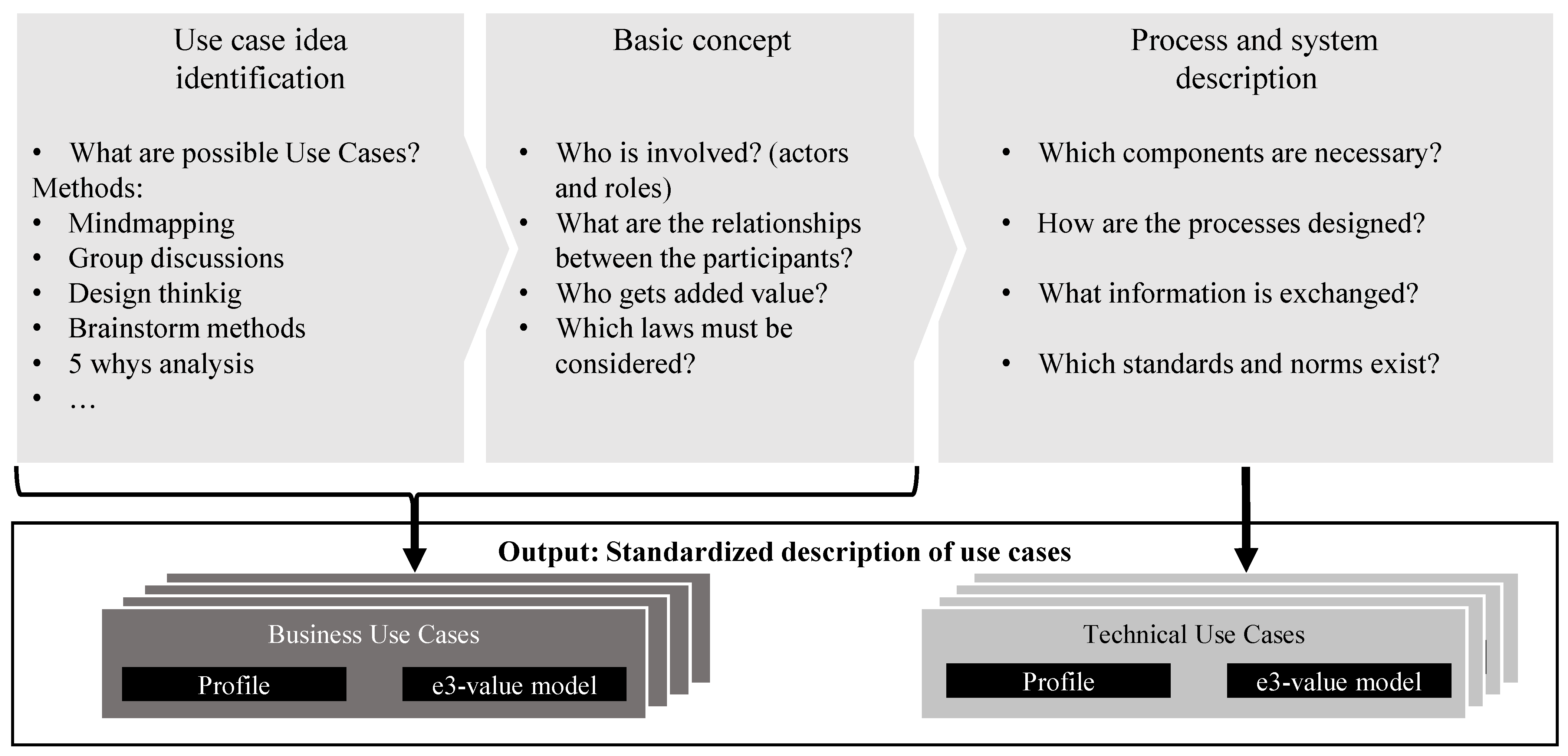
Based on the mentioned methods as well as experience from these projects, FfE developed the unIT-e2 use-case methodology. Figure 1 shows the schematic procedure.
At first, the unIT-e2 use-case methodology deducts the former three steps from Faller et al. into two use-case levels: business-use case (BUC) and technical-use case (TUC). The first level, BUC, consists of the use-case identification and the basic concept. To identify a use-case idea, various methods such as mind mapping, design thinking, and others can be applied. For the basic concept of the use case, the following questions need to be answered: who is involved, what are the relationships between participants, who gets added value, and which laws must be considered? Further, the desired implementation needs to be defined. Therefore, five different implementation stages can be distinguished: conceptual, simulation, laboratory, pilot operation, and real operation. The conceptual stage solely analyzes the use case on a conceptual basis, while simulation means that the use case is investigated by simulation models. A laboratory implementation tests a use case under technical and/or regulatory development in a protected development environment without a direct connection to the public power grid. For pilot operation, a use case under technical and/or regulatory development is tested with connection to the public power grid with preferably “friendly users” on a limited scale. The final implementation real operation tests a technically and regulatory-compliant use case with not necessarily certified or approved components in the real end-customer sector. The second level and one level more profound is the TUC, comprising step 2 and communication format, channels, and standards from step 3 of the use-case method defined by Faller et al. [32]. The specification of the processes applied by Faller et al., corresponding to internal processes in companies via sequence diagrams, is too detailed for discussing the use case with the number of project partners involved in unIT-e2. Therefore, the TUC focuses on the technical components (soft- and hardware) involved and their interaction with each other and not on the exact process sequence. The necessary process specification takes place after the unIT-e2 use-case methodology. For each use-case level, a description template and an e3-value model template for visualizing relevant relationships are created. Hence, long texts are avoided by using icons and graphics. The BUC template describes the use case on a high level, includes relevant participants, describes the benefit, how the use case is to be implemented in the project, and states the overall goal of the use case. The BUC e3-value model visualizes relationships and interactions between participants. The TUC template describes the processes, participants, relevant technical components, and involved communication protocols, norms, and standards. The TUC e3-value model includes all relevant components and their data and communication interfaces. The description template, as well as the e3-value for both BUCs and TUCs, are limited to two PowerPoint pages each, resulting in four pages in total to describe one use case.
At the beginning of the project, several workshops were conducted in each cluster to develop use cases to be demonstrated in field trials. Depending on the particular use case and the number of involved project partners, it took several workshop sessions to complete the process visualized in Figure 1. A glossary was written to foster a uniform understanding of recurring terms. In the end, the standardized use-case templates constitute the foundation for the field tests of the project

4. Resulting Business Use Cases in unIT-e2

The unIT-e2 use-case methodology was applied in all four clusters, which resulted in the 25 higher-level BUCs displayed in Figure 2. Depending on the location of the flexibility and the direction of power flow, the BUCs can be subdivided into more than 40 individual BUCs, as stakeholders, responsibilities, and requirements differ for these cases. Different implementation steps are planned for the various BUCs. Some will only be analyzed by simulation or tested in a laboratory environment rather than demonstrated during the field trials. The following section discusses the higher-level BUCs to reduce complexity.
We categorized the BUCs in two dimensions: per unIT-e2 cluster in which the BUC will be implemented and per origin of the incentive signal, i.e., the key source, which creates an incentive for the BUC to be implemented. The origin of the incentive signal is divided into three types: 1. local/on-site, 2. electricity market, and 3. grid/system. Further, these incentives can be subdivided into different use-case categories displayed on the left. For each cluster, five to eight BUCs were identified. Five use cases are incentivized locally/at the site where the technical implementation takes place. Seven use cases are incentivized by variable market prices resulting from the electricity spot markets. The largest group of 13 BUCs is incentivized by the electric grid or, more precisely, by the possibility to reduce grid load, avoid grid congestions, and thus optimize grid use and avoid grid expansion.

4.1. Incentive Signal: Local/On Site

The category of locally incentivized BUCs contains two similar BUCs called increased PV self-consumption, one from the cluster sun-E and one from the cluster Harmon-E. Both will be implemented at private homes with a PV system and a home energy management system (HEMS), which optimizes the self-consumption behind the meter. On a technical level, both approaches require a smart metering system that allows EEBUS communication, which is a communication interface based on standards and norms, with the HEMS and PV-forecast data. The main difference between both BUCs is that, for the cluster Harmon-E, bidirectional EVs will be tested in a laboratory environment in addition to the unidirectionally chargeable EVs in the field trial. The BUC peak-shaving in this category is comparable to the BUC building optimization. Both use cases aim to optimize the use of available power at the grid connection point by avoiding peak loads and corresponding fees. The optimization of flexible loads is implemented behind the meter in both cases. While both cases are to be implemented in apartment buildings or commercial sites with unidirectional EVs, peak-shaving in the cluster Harmon-E will also be tested in a single home, and bidirectional EVs will be tested in a laboratory environment. For peak-shaving in apartment buildings/commercial sites, an aggregator will operate the charging strategy, whereas for building management, an energy management system (EMS) will manage different flexibilities from various owners under potential grid restrictions.

4.2. Incentive Signal: Electricity Market

Out of the seven use cases incentivized by market prices, three use cases aim at reducing greenhouse gas emissions, which are GHG-optimized electricity consumption, CO2-optimized charging in a smart quarter, and CO2-optimized charging of a vehicle fleet. These use cases aim to minimize the direct emissions of electricity for charging the EV, when forecast data regarding the greenhouse gas emissions of electricity are needed in an appropriate temporal resolution. The BUCs differ in the planned implementation, as cluster sun-E will mainly simulate its BUCs for a single home, whereas cluster Heav-E will test the two BUCs in field trials in a smart quarter (apartment block) and for a fleet of EVs. On a technical level, the role of optimization varies. In sun-E, the HEMS optimizes based on emission data. In Heav-E, for the smart-quarter BUC, the smart-quarter manager optimizes all flexible assets with varying restrictions and objectives. For the vehicle-fleet case, this role is the fleet manager. In four BUCs, varying spot market prices are utilized to minimize electricity costs. For all four cases, the energy provider has market access, from which market prices are derived and passed either directly to the local EMS via a secure SMGW pathway or to an aggregator. The cases of market-oriented flexibility via price incentives and market optimization (dynamic tariffs) do not involve any aggregator, but instead market price tables are transmitted to the local HEMS, wherein the charging strategy is optimized locally. For the cases market (and grid) serving flexibility and market-oriented flexibility via trading profits, an aggregator either sends price tables to the local HEMS of a single home or sends flexibility schedules, which in turn determine the charging strategy for apartment buildings or commercial sites.

4.3. Incentive Signal: Grid/System

From the category of use cases incentivized by optimizing the electric grid, three BUCs are based on variable electricity prices, which are derived from the forecasted grid load. These cases have in common that a hypothetical variable grid usage fee is introduced by the grid operator based on the time-dependent local grid load. The grid operator thus needs locally and temporally resolved grid status data. In all cases, the local EMS receives variable price signals, which are included in the behind-the-meter optimization. For the BUC grid-serving flexibility via price incentives (sun-E), the variable grid fee will contain both a price component based on long-term forecasts and a component based on dynamic short-term predictions. The BUC adaption of charging behavior by price signals shows the feature that not only single home and apartment blocks/commercial sites are part of the field trials but also public charging. Each cluster includes one BUC with a strict load limit, which is set by the grid operator depending on the grid load at the respective time (i.e., the German §14a EnWG regulation or a possible future adaptation of the originally planned paragraph). For all these cases, reduced grid fees are considered, which are accounted for by the energy provider. In all cases, the grid operator sends a load limit signal via the smart-metering-system infrastructure to the grid connection point, where a local EMS must adjust the local power consumption accordingly. Two use cases aim at generally improved grid management through extensive data collection and automation. Key objectives in both cases are the monitoring and forecast of grid status to determine grid congestion and to derive required actions, such as load limits. Necessary data should be acquired through conventional measuring points, such as electric transformers, and new grid status data from local smart-metering systems. The lower four BUCs are linked to grid system services to maintain overall grid stability. For all these BUCs, an aggregator is needed who participates in one of the respective marketplaces and offers flexibility from pooled assets. If an offer is accepted, the offered flexibility is used to provide the respective system service, wherein the aggregator receives a command signal from the grid operator if necessary. The roles of the different players involved differ for the different use cases. e.g., in sun-E, the OEM functions as an aggregator, whereas for the other cases, the aggregator receives required data from the OEM’s backend or the local EMS.

5. Business Use Case: Regulatory-Defined Grid-Serving Flexibility

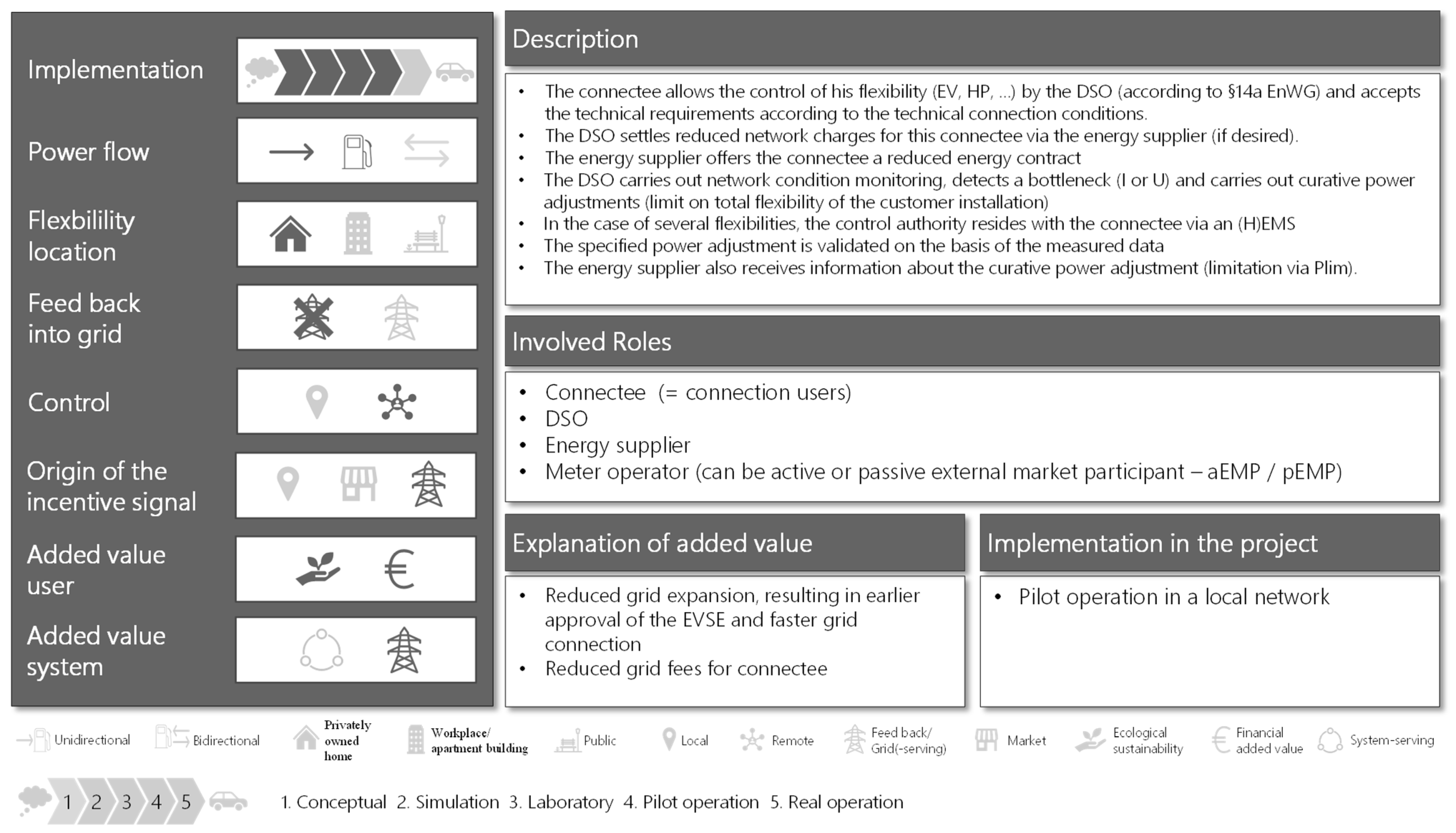
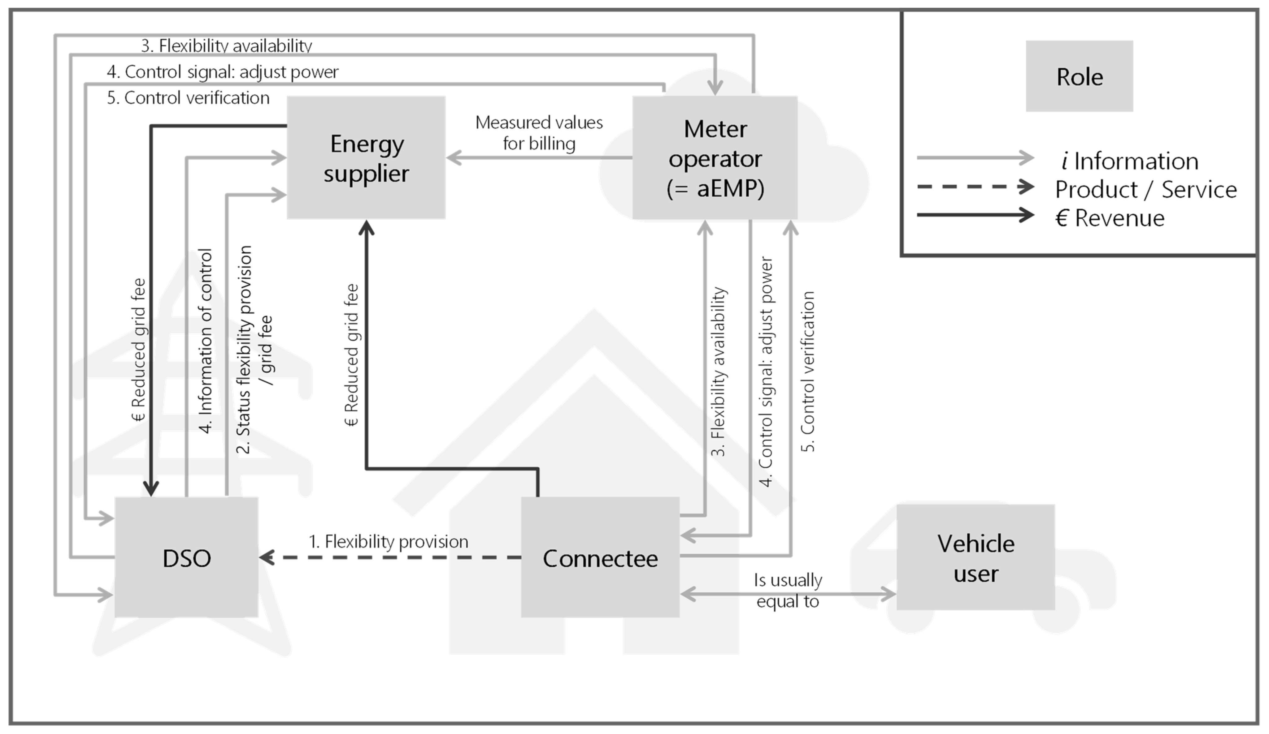
Since all clusters will test a use case from the category direct grid constraint and the discussions about the reform of §14a EnWG, the following section describes the BUC regulatory-defined grid-serving flexibility from cluster Harmon-E in more detail. Depending on the power flow and the location of the flexibility, the use case can be further divided into three individual use cases. However, the overall goal remains the same: enable the distribution operator (DSO) to control the flexibility within a regulatory-defined framework. Figure 3 shows the template description (top) and the e3-value model (bottom) for the individual BUC regulatory-defined grid-serving unidirectional flexibility for privately owned homes.
This use case will be implemented in Harmon-E in pilot operation. The power flow is unidirectional; the location of the flexibility is a privately owned home; there is no feedback into the grid, and the flexibility is remotely controlled. The incentive signal origins from the grid. The user becomes ecological/sustainable, and there is also financial added value. The use case can be categorized as grid serving. A detailed description of the definition of grid serving can be found in [46]. The involved roles are connectee (in this case connectee = connection user), DSO, energy supplier, and meter operator. The meter operator can either be an active or passive market participant or both (aEMP/pEMP), resulting in two more BUCs than the one presented. First, the connectee allows the control of his flexibility (e.g., EV, HP, battery storage) by the DSO (according to §14a EnWG) and accepts the technical requirements according to the technical connection conditions. Therefore, the DSO settles reduced network charges for this connectee via the energy supplier. The energy supplier offers the connectee a reduced energy contract. The DSO carries out network condition monitoring and if he detects grid congestion, the DSO performs curative power adjustments by limiting the total flexibility of the customer installation. If the connectee has several flexibilities, the control authority of these flexibilities resides with the connectee via an (H)EMS. The specified power adjustment (PLim) is validated based on the measured data, and the energy supplier also receives information about the curative power adjustment. Figure 3 shows the case when the meter operator functions as an aEMP. The different roles are a result of the rollout of the smart-meter infrastructure. The aEMTs do not only receive data but can also control downstream devices via the SMGW. To control the flexibility, the aEMP must send a communication request to the gateway administrator (GWA). However, this process is part of the TUC rather than the BUC. The general procedure for controlling flexibilities via the smart-meter infrastructure is described in [47]. An aEMT must therefore have certification in accordance with ISO/IEC 27001, which covers all smart-meter public-key infrastructure-relevant processes and IT systems [48]. On the other hand, pEMPs can only receive data from SMGWs. This is a prerequisite for pEMPs to be able to handle their business processes, e.g., to create invoices and determine network states based on received meter values. The other possible variant of the use case would be if the DSO functions as an aEMP and the meter operator as a pEMP. In the following step, the template description and the e3-value model shown in Figure 3 serve as a basis for the design of the corresponding TUC.

6. Technical Use Case: Regulatory-Defined Grid-Serving Flexibility

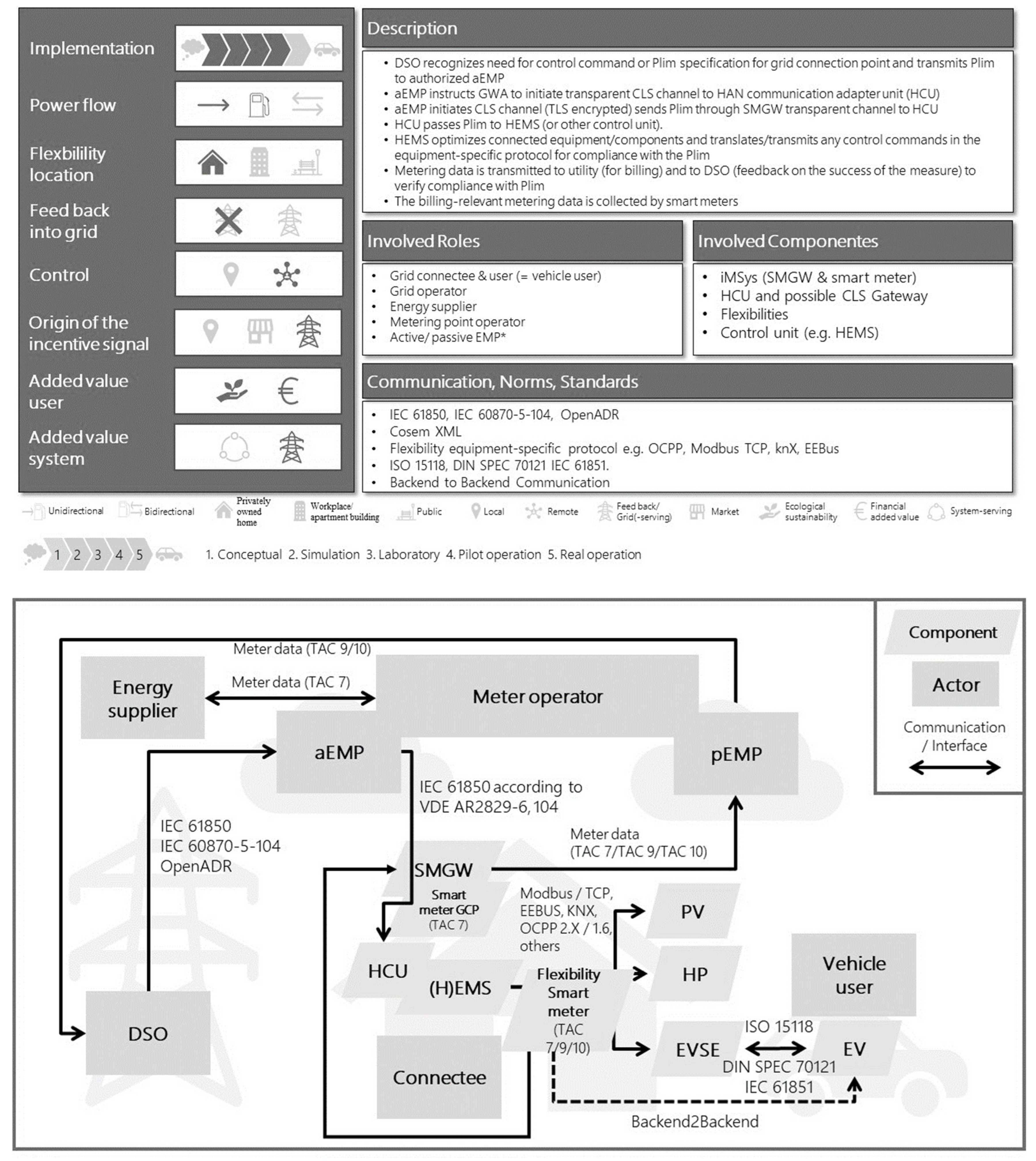
The following section describes one possible technical implementation of the use-case regulatory-defined grid-serving flexibility for privately owned home as it will probably be tested in cluster Harmon-E. Figure 4 shows the template description (top) and the e3-value model (bottom) for the technical use case.
The technical use case proceeds as follows. The DSO recognizes the need for a control command or a Plim specification for the grid connection point (GCP) and transmits the Plim to an authorized aEMP. The applicable standards for communication are IEC 61850, IEC 70870-5-104, and OpenADR. Again, the meter operator acts as an aEMP. The aEMP instructs the GWA to initiate a transparent CLS channel to the HAN communication adapter unit (HCU). The aEMP initiates the establishment of a controllable local system (CLS) channel (TLS encrypted) and sends the Plim signal through the SMGW transparent channel to the HCU, which is the endpoint of the CLS channel. In correspondence with [23], the transmission via a CLS proxy corresponds to stage 3 of the stage model. Once again, the IEC 61,850 following VDE AR2829-6 offers a communication standard. Afterwards, the HCU passes the Plim signal to a HEMS. Another possibility is that the HCU passes the Plim signal directly to a control unit (e.g., PV, HP, EVSE). The HEMS optimizes the connected equipment/flexibilities, translates, and transmits any control commands in the equipment-specific protocol for compliance with the Plim. Depending on the flexibility, multiple protocols are possible (e.g., EEBUS, Modbus/TCP, OCPP, KNX, …). Another possible transmission is the backend-to-backend communication of the component manufacturers. Between the EVSE and EV, the possible communication standards are ISO 15118, DIN SPEC 70121, and IEC 61851. Metering data is transmitted via the SMGW according to the tariff application cases (TAC, German: Tarifanwendungsfall) 7, 9 or 10 to the energy supplier (for billing) and the DSO to verify adherence to the Plim signal [49]. In compliance with German calibration regulations, every flexibility needs a separate calibrated metering point to be used by §14a EnWG. If the Plim signal refers to the GCP, then one grid connection meter is sufficient. If the Plim signal refers to a single control unit, usage of the meter data from the HEMS would be interesting to avoid additional meters. However, this is currently not in compliance with German calibration regulations. Nevertheless, in future, this might represent an attractive alternative solution.

7. Conclusions and Outlook

In summary, this paper describes a use-case methodology oriented towards practical use. The methodology is based on existing norms and standards, as well as experience from other projects. The use-case methodology was applied in all four clusters resulting in several BUCs and TUCs. Most of the BUC descriptions are published on the project website https://unit-e2.de/ (accessed on 17 December 2022) [17]. The methodology supports a common understanding of the research subject and wording and thus constitutes a solid basis for the first project phase. The simplified method is constructed such that every project partner, even those with limited time and/or limited interest in scientific analysis, are capable and motivated to participate. The major advantage of this approach is that it yields quick results, which enable further preparation for the field tests. The documentation is reduced but still sufficient so that all stakeholders, even those without specific expertise, can understand the essential components of the use case in a short time. Further, the brief description and the graphic representation as an e3-value model are impactful and readily comprehensible for new project staff or external stakeholders, even those without specific expertise. The simplicity of the unIT-e2 use-case methodology is an advantage and at the same time also a drawback. While the use-case descriptions are sufficiently detailed for project staff to understand the process, software developers, for example, need detailed sequence diagrams for implementation. These additional specifications of certain processes and/or interfaces are necessary but not part of the unIT-e2 use case methodology. To develop valuable business models, further steps are also needed. Another limitation of the paper is we cannot yet publish more than one TUCs at this point. In future work, we plan to publish further selected TUCs. Additionally, in the unIT-e2 subproject research, most of the BUCs will be implemented and examined in various simulation environments. With the FfE model, the Electric Grid and Energy System Model for Distribution Grids—GridSim effects of the use cases on e.g., grid loads in various grids (urban and rural) will be examined [50]. Further, implementation of the use cases in the FfE model electric Flexibility assessment modelling environment—eFlame will allow the investigation of current and future revenues [51]. Future research should be devoted to the development of a system architecture derived from the BUC and TUC, which enables a full understanding of the whole system rather than focusing on one use case. Another interesting topic for future work is the systematic assessment of the combination possibilities of the use cases.

Author Contributions

Conceptualization, A.O. and P.D.; methodology, A.O and P.D.; validation, A.O., P.D. and V.Z.; formal analysis, A.O. and P.D.; investigation, V.Z.; resources, A.O.; writing—original draft preparation, A.O., P.D. and V.Z. writing—review and editing, A.O.; visualization, A.O. and P.D.; supervision, A.O.; project administration, A.O.; funding acquisition, A.O. All authors have read and agreed to the published version of the manuscript.

Funding

This research was conducted as part of the activities of FfE in the project “unIT-e2—Living Lab for Integrated E Mobility”. The project is funded by the Federal Ministry for Economic Affairs and Climate Action (BMWK) (funding code: 01MV21UN11 (FfE e.V.), 01MV21UN01 (FfE GmbH)).

Data Availability Statement

Not applicable.

Acknowledgments

Special thanks go to all unIT-e2 partners involved in the process and the various workshops. Further, we like to thank Katharina Sommer, Ryan Harper and Robbie Göb.

Conflicts of Interest

The authors declare no conflict of interest.

Abbreviations

The following abbreviations are used in this manuscript:
BCMBidirectional Charging Management
BUCBusiness-Use Case
CLSControllable Local System
DSODistribution Network Operator
EMSEnergy Management System
EUEuropean Union
EVElectric Vehicle
EVSEElectric Vehicle Supply Equipment
GCPGrid Connection Point
GHGGreenhouse Gas
GWAGateway Administrator
HANHome Area Network
HCUHAN Communication Adapter Unit
HEMSHome Energy Management System
HPHeat Pump
OEMOriginal Equipment Manufacturer
SGAMSmart Grid Architecture Model
SMGWSmart Meter Gateway
SPSub Project
TUCTechnical-Use Case
UMLUnified Modeling Language

References

  1. Paris Agreement; Version 2015; United Nations: Paris, France, 2015.
  2. EEA Greenhouse Gases-Data Viewer. Available online: https://www.eea.europa.eu/data-and-maps/data/data-viewers/greenhouse-gases-viewer (accessed on 10 February 2022).
  3. Bird, L.; Debra, L.; Millian, M.; Carilini, M.; Estanqiero, A.; Flynn, D.; Gomez-Lazaro, E.; Holttingen, H.; Menemenlis, N.; Orths, A.; et al. Wind and solar energy curtailment: A review of international experience. Renew. Sustain. Energy Rev. 2016, 65, 577–586. [Google Scholar] [CrossRef] [Green Version]
  4. Denholm, P.; Hand, M. Grid flexibility and storage required to achieve very high penetration of variable renewable electricity. Energy Policy 2011, 39, 1817–1830. [Google Scholar] [CrossRef]
  5. Bistline, J. Economic and technical challenges of flexible operations under large-scale variable renewable deployment. Energy Econ. 2017, 64, 363–372. [Google Scholar] [CrossRef]
  6. Guerra, K.; Haro, P.; Gutiérrez, R.; Gómez-Barea, A. Facing the high share of variable renewable energy in the power system: Flexibility and stability requirements. Appl. Energy 2022, 310, 118561. [Google Scholar] [CrossRef]
  7. Mathiesen, B.V.; Lund, H.; Connolly, D.; Wenzel, H.; Østergaard, P.A.; Möller, B.; Nielsen, S.; Ridjan, I.; Karnøe, P.; Sperling, K. Smart Energy Systems for coherent 100% renewable energy and transport solutions. Appl. Energy 2015, 145, 139–154. [Google Scholar] [CrossRef]
  8. Mathiesen, B.V.; Connolly, D.; Lund, H.; Nielsen, M.P.; Schaltz, E.; Wenzel, H.; Bentsen, N.S.; Felby, C.; Kaspersen, P.; Ridjan, I. CEESA 100% Renewable Energy Transport Scenarios towards 2050—Technical Background Report Part 2; Aalborg University: Copenhagen, Denmark, 2015. [Google Scholar]
  9. Duscha, V.; Wachsmuth, J.; Eckstein, J.; Pfluger, B. GHG-Neutral EU2050—A Scenario of an EU with Net-Zero Greenhouse Gas Emissions and Its Implications; Umweltbundesamt: Dessau-Roßlau, Germany, 2019. [Google Scholar]
  10. National Emissions Reported to the UNFCCC and to the EU Greenhouse Gas Monitoring Mechanism; European Environment Agency (EEA): Copenhagen, Denmark, 2020. Available online: https://www.eea.europa.eu/data-and-maps/data/national-emissions-reported-to-the-unfccc-and-to-the-eu-greenhouse-gas-monitoring-mechanism-16 (accessed on 27 February 2022).
  11. Bieker, G. A Global Comparison of the Life Cycle Greenhouse Gas Emissions of Combustion Engine and Electic Passenger Cars; The International Council on Clean Transportation: Berlin, Germany, 2021. [Google Scholar]
  12. Dornoff, J.; Mock, P.; Baldino, C.; Bieker, G.; Díaz, S.; Miller, J.; Sen, A.; Tietge, U.; Wappelhorst, S. Fit for 55: A Review and Evaluation of the European Commission Proposal for Amending the CO2 Targets for New Cars and Vans; The International Council on Clean Transportation: Berlin, Germany, 2021. [Google Scholar]
  13. Total Market Share of Newly Registered Passenger Electric Vehicles in the European Union between 2015 and 2020. Available online: https://www.statista.com/statistics/625010/electric-vehicle-market-share-in-eu-annual/ (accessed on 20 May 2022).
  14. Volkswagen Naturstrom. Available online: https://www.elli.eco/en/green-energy (accessed on 9 May 2022).
  15. Tesla Stromtarif. Available online: https://www.tesla.com/de_de/tesla-stromtarif (accessed on 9 May 2022).
  16. Verordnung über Allgemeine Bedingungen für den Netzanschluss und dessen Nutzung für die Elektrizitätsversorgung in Niederspannung (Niederspannungsanschlussverordnung—NAV); Bundesrepublik Deutschland: Berlin, Germany, 2006.
  17. Project Webpage unIT-e²: Living Lab for Integrated e-Mobility. Available online: https://unit-e2.de/ (accessed on 29 August 2022).
  18. Gesetz über Die Elektrizitäts- und Gasversorgung (Energiewirtschaftsgesetz) (EnWG); Version 2018; Bundesministerium der Justiz und für Verbraucherschutz: Berlin, Germany, 2018.
  19. European Commission v Federal Republic of Germany. Failure of a Member State to fulfil Obligations—Internal Markets for Electricity and Natural Gas (Case C-718/18); Court of Justice of the European Union: Luxembourg, 2021. [Google Scholar]
  20. Pressemittelung zur Berichterstattung in der Heutigen Welt am Sonntag zu Thema Laden von E-Autos. Available online: https://www.bmwk.de/Redaktion/DE/Pressemitteilungen/2021/01/20210117-berichterstattung-welt-am-sonntag-laden-von-e-autos.html (accessed on 9 May 2022).
  21. Gesetz zur Digitalisierung der Energiewende; Version 2016; Bundesministerium für Wirtschaft und Energie (BMWi): Bonn, Germany, 2016.
  22. Ziemsky, V.; Biedenbach, F.; Matzner, A. Systemintegration von Elektrofahrzeugen—Stromlieferverträge mit Nicht-Statischen Tarifen-FfE Grundlagenpapier; Forschungsstelle für Energiewirtschaft (FfE): München, Germany, 2022. [Google Scholar]
  23. Stufenmodell zur Weiterentwicklung der Standards für Die Digitalisierung der Energiewende; Bundesamt für Sicherheit in der Informationstechnik: Berlin, Germany; Bundesministerum für Wirtschaft und Energie: Bonn, Germany, 2020.
  24. Müller, M.; Biedenbach, F.; Reinhard, J. Development of an Integrated Simulation Model for Load and Mobility Profiles of Private Households. Energies 2020, 13, 3843. [Google Scholar] [CrossRef]
  25. Doppelter Haushaltsstromverbrauch mit Elektroauto. Available online: https://www.vbew.de/energie/presseinfos-energie/news/doppelter-haushaltsstromverbrauch-mit-elektroauto (accessed on 11 May 2022).
  26. Cockburn, Alistair: Writing Effective Use Cases; Addison-Wesley Professional: Boston, MA, USA, 2000.
  27. IEC SRD 62913-1:2019; Generic Smart Grid Requirements (Part 1: Specific Application of the Use Case Methodology for Defining Generic Smart Grid Requirements According to the IEC Systems Approach). International Electrotechnical Commission: Geneva, Switzerland, 2019.
  28. Oestereich, B. Analyse und Design Mit der UML 2.5—Objektorientierte Softwareentwicklung; Oestereich: München, Germany, 2012. [Google Scholar]
  29. IEC 62559-2:2015; Use Case Methodology—Part 2: Definition of the Templates for Use Cases, Actor List and Requirements List. Issued 2015-04; International Electrotechnical Commission: Geneva, Switzerland, 2015.
  30. Gordijn, J.; Akkermans, J.M. Value-based requirements engineering exploring innovative e-commerce ideas. Requir. Eng. 2003, 8, 114–134. [Google Scholar] [CrossRef]
  31. CEN-CENELEC-ETSI. Smart Grid Coordination Group: SG-CG/M490/K_ SGAM Usage and Examples—SGAM User Manual—Applying, Testing & Refining the Smart Grid Architecture Model (SGAM); Version 3.0; CENELEC: Brüssel, Belgien, 2014. [Google Scholar]
  32. Faller, S.; Bogensperger, A.; Köppl, S.; Kießling, A. Anwendungshilfe Use Case Methodik—Eine praktische Anwendungshilfe für die Use Case Entwicklung; Forschungsstelle für Energiewirtschaft e. V. (FfE): München, Germany, 2020. [Google Scholar]
  33. Weigand, H.; Johannesson, P.; Andersson, B.; Bergholtz, M.; Edirisuriya, A.; Ilayperuma, T.; Ribbers, P. Strategic analysis using value modeling—The c3-value approach. In Proceedings of the 40th Hawaii International Conference on System Sciences, Waikoloa, HI, USA, 3–6 January 2007; Tilburg University: Tilburg, The Netherlands, 2007. [Google Scholar]
  34. IEC 62559—Use Case Methodology. Available online: https://syc-se.iec.ch/deliveries/iec-62559-use-cases/ (accessed on 9 May 2022).
  35. CEN-CENELEC-ETSI. Smart Grid Coordination Group: SG-CG/M490/I_Smart Grid Interoperability—Methodologies to Facilitate Smart Grid System Interoperability through Standardization, System Design and Testing; CEN-CENELEC-ETSI: Brüssel, Belgium, 2014. [Google Scholar]
  36. IEEE Standard Computer Dictionary: A Compilation of IEEE Standard Computer Glossaries; Issued 1991-01-18; IEEE: New York, NY, USA, 1991.
  37. Faller, S.; Schütz, J.; Bogensperger, A.; Uslar, M. Anwendungshilfe SGAM—Smart Grid Use Cases modellieren. In Energiwirtschaftliche Tagesfragen; Forschungsstelle für Energiewirtschaft e. V. (FfE), OFFIS e.V.: Offenbach, Germany, 2020. [Google Scholar]
  38. CEN-CENELEC-ETSI. Smart Grid Coordination Group: SG-CG/ M490/F_ Overview of SG-CG Methodologies; CENELEC: Brüssel, Belgien, 2014. [Google Scholar]
  39. Frein, C. Rollenmodell für Die Marktkommunikation im Deutschen Energiemarkt—Anwendungshilfen—Strom und Gas; BDEW Bundesverband der Energie- und Wasserwirtschaft e.V.: Berlin, Germany, 2016. [Google Scholar]
  40. ENTSO-E. The Harmonised Electricity Market Role Model; entso-e aisbl: Brüssel, Belgien, 2017. [Google Scholar]
  41. EASEE-Gas. Harmonised Gas Role Model Specification; EASEE-Gas: Paris, France, 2016. [Google Scholar]
  42. Business Process Model and Notation (BPMN); Object Management Group: Needham, MA, USA, 2011.
  43. InDEED—Konzeption, Umsetzung und Evaluation einer auf Blockchain Basierenden Energiewirtschaftlichen Datenplattform für die Anwendungsfälle “Labeling” und “Asset Logging”. Available online: https://www.ffe.de/projekte/indeed/ (accessed on 11 May 2022).
  44. Trade-EVs II—Trade of Renewable, Aggregated and Distributed Energy by Electric Vehicles. Available online: www.ffe.de/tradeEVsII (accessed on 1 January 2021).
  45. Bidirektionales Lademanagement (BDL)—Intelligentes Zusammenspiel von Elektrofahrzeugen, Ladeinfrastruktur und Energiesystem. Available online: https://www.ffe.de/projekte/bdl/ (accessed on 9 January 2021).
  46. Schulze, Y.; Müller, M.; Faller, S.; Duschl, W. Was ist Netzdienlichkeit? In et-Energiewirtschaftliche Tagesfragen; Forschungsstelle für Energiewirtschaft (FFE e.V.): München, Germany, 2021. [Google Scholar]
  47. Bogensperger, A.; Estermann, T.; Samweber, F.; Köppl, S.; Müller, M.; Zeiselmair, A.; Wohlschlager, D. Smart Meter—Umfeld, Technik, Mehrwert; Forschungsstelle für Energiewirtschaft e.V.: München, Germany, 2018. [Google Scholar]
  48. Bundesamt für Sicherheit in der Informationstechnik (BSI). Zertifizierung nach ISO 27001 auf der Basis von IT-Grundschutz—Zertifizierungsschema; Version 1.2; Bundesamt für Sicherheit in der Informationstechnik (BSI): Bonn, Germany, 2014. [Google Scholar]
  49. Technische Richtlinie BSI TR-03109-1—Anforderungen an die Interoperabilität der Kommunikationseinheit Eines Intelligenten Messsystems; Version 1.1; Bundesamt für Sicherheit in der Informationstechnik: Bonn, Germnay, 2021.
  50. FfE Model: GridSim—Electric Grid and Energy System Model for Distribution Grids. Available online: https://www.ffe.de/en/tools/gridsim-electricity-grid-and-energy-system-model-for-distribution-grids/ (accessed on 1 December 2022).
  51. FfE Model: eFlame—Electric Flexibility Assessment Modeling Environment. Available online: https://www.ffe.de/tools/eflame-electric-flexibility-assessment-modeling-environment/ (accessed on 1 December 2022).
Figure 1. unIT-e2 use-case methodology.
Wevj 14 00013 g001aWevj 14 00013 g001b
Figure 2. Overview of BUCs in unIT-e2 project grouped per cluster and incentive signal.
Wevj 14 00013 g002
Figure 3. BUC regulatory-defined grid-serving unidirectional flexibility for privately owned home: description template (top) and e3-value model (bottom).
Wevj 14 00013 g003aWevj 14 00013 g003b
Figure 4. TUC regulatory-defined grid-serving unidirectional flexibility for privately owned home: description template (top) and e3-value model (bottom).
Wevj 14 00013 g004
Disclaimer/Publisher’s Note: The statements, opinions and data contained in all publications are solely those of the individual author(s) and contributor(s) and not of MDPI and/or the editor(s). MDPI and/or the editor(s) disclaim responsibility for any injury to people or property resulting from any ideas, methods, instructions or products referred to in the content.