Abstract
A method for real-time estimation of rotor flux linkage of permanent-magnet synchronous machines (PMSMs) under both steady state and free-running conditions is proposed in this paper. At steady state, a method for the estimation of rotor flux linkage is proposed based on the injection of variable-period zero-voltage perturbation, of which the accuracy is irrespective of the influence of voltage-source inverter (VSI) nonlinearity. Moreover, for the estimation of rotor flux linkage under free-running condition, due to system inertia after shutdown or fault in the motor driver, an effective approach using history data recorded at different transients of rotor speeds is developed, which has eliminated the influence of VSI nonlinearity during the modeling process. The proposed two methods are experimentally validated on a down-sized PMSM prototyped for electric vehicle application, which shows good performance for the estimation of rotor flux linkage under both steady state and free-running conditions.
1. Introduction
Thanks to its high torque density and high efficiency, the permanent-magnet synchronous machine (PMSM) has been widely used in industrial applications such as electric vehicles (EVs) and industrial servo drives [1,2]. However, for electric vehicles using PMSMs, their rotor permanent magnets (PMs) might suffer from irreversible demagnetization due to temperature rise and large demagnetization current [3,4,5,6]. Therefore, in order to monitor the status and potential faults of PMs, the accurate information of rotor flux linkage, which decreases with the increases of PM temperature, has become an essential factor. In addition, the real-time information of rotor flux linkage is also necessary for high performance controls such as the maximum torque per ampere control and sensorless control [7,8,9].
Recently, the real-time estimation of rotor flux linkage has been widely investigated for operations under steady state. However, the estimation of rotor flux linkage and other machine parameters will inevitably suffer from equation rank-deficient problems, which can lead to divergence or wrong convergence of results [10]. Moreover, in a PMSM drive system, the command voltage from the proportional integral (PI) controller is often employed for replacing the real voltage for control algorithms [11]. However, due to the existence of voltage source inverter (VSI) nonlinearity, the command voltage is not equal to the real PMSM voltage, which will greatly affect the accuracy of parameter estimation.
To solve the rank-deficient problem in parameter estimation of PMSM, many methods have been developed [12,13,14,15,16,17,18,19,20,21,22,23,24,25]. A typical method is based on observation or identification algorithms, such as model reference adaptive system [12], recursive least square [13,14], and extended Kalman filters [15]. Two RLS algorithms, being fast and slow, respectively, are employed in [12] to estimate four electrical parameters of a PMSM. The faster one estimates the d-axis and q-axis inductance, which are affected by magnetic saturation due to varying currents. While the slower one is devoted to the estimation of winding resistance and rotor flux linkage, which are mainly affected by the machine temperature. Similarly, the methods used in [16,17] also adopt the two-stage algorithms to estimate machine parameters. A potential disadvantage is that the inaccurate estimation of inductances will lead to errors in the identification of winding resistance. In addition, it is also possible to construct a full-rank identification model by setting the parameters that do not need to be identified as fixed values or offline measured values [18,19,20]. However, this kind of solution will easily suffer from mismatched parameters and result in large estimation errors. Another method for constructing a full-rank identification model is to inject disturbance signals into the PMSM for online parameter estimation, such as DC voltage pulse [21], d-axis currents [22], zero-voltage vector [23], harmonic current [24], and position-offsets [25]. Nevertheless, the injection of disturbance signals may bring adverse effects to the machine, such as increasing machine losses and reducing the stability of the drive system.
To eliminate the influence of VSI nonlinearity on parameter identification, numerous methods have been investigated [11,26,27,28,29,30]. The most conventional method is to establish a disturbance observer based on the accurate mathematical model of VSI [11], in which the VSI nonlinearity is modeled as a distorted voltage term and can be eliminated by online compensation. However, in real applications, the hardware parameters are not always available, and voltage drops of power devices are varying under different operating conditions. Since the distorted voltage due to VSI nonlinearity is mainly composed of the 6th harmonic, it can be eliminated by the harmonic suppression solution [26,27,28]. In [26], it was assumed that only VSI nonlinearity leads to 6th harmonics in dq-axis voltages, while the influence of 6th harmonic in back-electromotive-force (EMF) was ignored. Hence, it is only suitable for PMSMs with sinusoidal back EMF, and its application scenarios are limited. Similarly, it was concluded in [29] that the derivative of the d-axis current harmonics will be the major error in the estimation of VSI nonlinearity. Moreover, the suppression of d-axis current harmonics can be achieved by the d-axis current control loop, which improves the identification accuracy of the parameters of surface-mounted PMSMs (SPMSMs). In addition, the distorted voltage due to VSI nonlinearity can also be estimated under variable speed conditions [30].
Based on the above analysis, it can be found that most existing studies on the estimation of rotor flux linkage and other machine parameters are conducted at steady state, and few researchers work on the identification of rotor flux linkage under the free-running condition. Therefore, this paper proposes a scheme for the real-time estimation of rotor flux linkage of PMSMs under both steady state and free-running conditions. Firstly, the rotor flux linkage will be estimated by an injection of variable-period zero-voltage perturbation at steady state, of which the accuracy is irrespective of the influence of VSI nonlinearity. The proposed method can reduce the potential adverse influence of d-axis voltage fluctuation on machine operation compared to reference [23]. Then, when the PMSM works under free-running condition due to system inertia after shutdown or fault in the motor driver, the rotor flux linkage will be estimated from data recorded at different transient speeds, which is also capable of eliminating the influence of VSI nonlinearity during the modeling process. Finally, the proposed method is experimentally validated on a down-sized PMSM prototyped for EV application, which shows good performance for the estimation of rotor flux linkage under both steady state and free-running conditions.
2. PMSM Modeling Including VSI Nonlinearity
The proposed rotor flux linkage estimation is based on the dq-axis PMSM model. In real applications, the dq-axis PMSM voltage model should include the distorted voltage resulted from VSI nonlinearity [26,30]. Thus, all analyses in this section are based on the PMSM model including VSI nonlinearity.
The transient-state dq-axis voltage equations of a PMSM are expressed below [4,8]:
where , , , , and are the actual dq-axis voltages, currents, and inductances, respectively; is the rotor flux linkage; R is the stator winding resistance; is the electrical angular speed.
In a PMSM drive system, voltage sensors are seldomly used and, thus, the command voltages of current-loop PI controllers are usually employed for replacing the actual voltages in parameter estimation. However, the command voltages are usually unequal to the actual voltages due to VSI nonlinearity, and their relationships are expressed below [26]:
where and are the command voltages; DdVdead and DqVdead are the dq-axis distorted voltages caused by VSI nonlinearity; Vdead is a constant when the PMSM is at steady state, and Dd and Dq can be denoted as [30]:
where γ is the angle between the current vector and q-axis; θ is the electrical angle. As shown in (3), Dd and Dq are periodical functions of θ and phase currents.
Substituting (2) into (1), it becomes
Hence, (4) is the transient-state dq-axis PMSM model including VSI nonlinearity.
3. Rotor Flux Linkage Estimation
In this section, the estimation model for rotor flux linkage under both steady state and free-running condition are deduced respectively.
3.1. Rotor Flux Linkage Estimation at Steady State Condition
Since the rotor flux linkage is in the q-axis equation, it can be calculated from the q-axis voltage by an appropriate estimation model. When the PMSM is operated under vector control, a zero-voltage perturbation is injected on the q-axis every N cycle of PWM switching (NTs), the corresponding q-axis equation can be expressed as (5) [23]. In other words, N cycles of PWM switching can be regarded as one control cycle, which consists of N − 1 cycles of vector control and one cycle for the injection of q-axis zero-voltage.
Combining (5) and (4) without injection of zero-voltage perturbation yields (6):
where , , and (DdVdead)vc are the q-axis command voltage, the dq-axis currents, and the q-axis distorted voltage due to VSI nonlinearity, respectively. , , and (DqVdead)inj represent the dq-axis currents and the q-axis distorted voltage due to VSI nonlinearity when there is an injection of zero-voltage perturbation.
When the PMSM is running at steady state, the q-axis command current determined by the output of speed-loop controller is dynamically fixed to a constant. Therefore, the current produced by N − 1 switching cycles of the vector control will be opposite to the variation trend of current during the cycle of zero-voltage perturbation injection. Therefore, (7) can be obtained as follows:
When Equation (6) is multiplied by N-1, the result is
Combining (7) and (8) yields:
Considering an SPMSM under id = 0 control and defining = (N − 1)(DqVdead)vc + (DqVdead)inj, Equation (9) can be simplified to (10):
To eliminate the influence of VSI nonlinearity, the distorted voltage can be cancelled through variable speed control. Two sets of different rotor speeds are denoted as and , respectively, and, according to (10), (11), and (12), they can be obtained in the form:
When the PMSM is under constant load torque or no-load condition, the q-axis current may be regarded as constant for different speeds, i.e., =, =. Therefore, subtracting (12) from (11), yields:
Equation (13) can be discretized by Euler’s method and simplified to (14):
where L is the length of Data 1 and Data 2, a and b are the ath and bth indices of Data 1 and Data 2, respectively. The command voltage and rotor speed are measurable; thus, the rotor flux linkage can be estimated directly by (14). The method in (14) not only eliminates the influences of inductance and winding resistance on rotor flux linkage, but is also irrespective of VSI nonlinearity. The schematic diagram and data measurement of the zero-voltage injection-based method under variable speed control are shown in Figure 1.
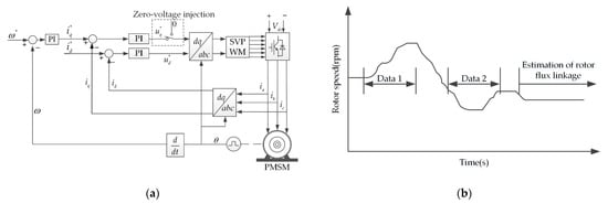
Figure 1.
Zero-voltage injection-based approach under variable speed control. (a) Schematic diagram of zero-voltage injection-based approach; (b) processes of data measurement and parameter estimation of the proposed method.
3.2. Rotor Flux Linkage Estimation at Free-Running Condition
The PMSMs used in electric vehicles or traction drive systems are usually with large moment of inertia. Once the inverter is suffering from a short-time power interruption or outage due to unexpected faults, the PMSM will go into the free-running condition due to the energy stored in inertia. The dq-axis model of a PMSM under the free-running condition is expressed below:
Equation (15) can be discretized by Euler’s method and simplified to (16):
where “k” is the index of the discrete sampling instant of drive system. When the PMSM goes into the free-running condition, the rotor speed of PMSM will transiently decrease due to power loss. As shown in Figure 2a, the current of PMSM is controlled to zero under current loop control, and the rotor speed of PMSM is controlled by the load machine. After the load machine is powered off, the PMSM goes into the free-running condition. As shown in Figure 2b, two sets of data (Data 3 and Data 4) corresponding to two sets of rotor speeds under the free-running condition are recorded and saved in the memory. Assuming that c and d are the cth and dth indices of Data 3 and Data 4, respectively, the two discrete-time q-axis voltage equations can be obtained as follows.
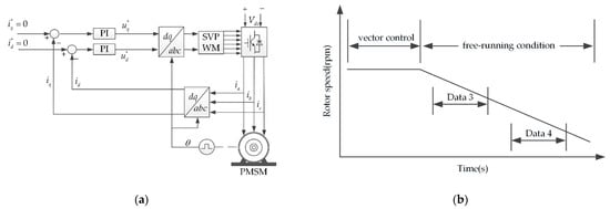
Figure 2.
Proposed method under free-running condition. (a) Current control diagram; (b) process of data measurement.
Thus, the rotor flux linkage is expressed below:
where M is the length of Data 3 and Data 4. Since the dq-axis currents are fixed to 0 by the current controllers, it is reasonable to treat Vdead as a constant. Hence, = while =, and ==. Then, (16) can be further simplified to (19):
Thus, the rotor flux linkage can be directly estimated from the recorded command voltages and rotor speed.
4. Experimental Results
4.1. Test Rig and Prototype PMSM
The proposed method for rotor flux linkage estimation is experimentally validated on a down-sized PMSM prototyped for EV application, as shown in Figure 3. The test PMSM is controlled by a Speedgoat equipped with Intel Celeron 2.0 GHz 4-core CPU, and fed by an insulated-gate bipolar transistor (IGBT) module, while the induction machine providing external load torque is controlled by an independent drive system. The position sensor used in the tested PMSM is a high-resolution incremental optical rotary encoder, which is of 5000 lines per revolution. The detailed design parameters of the tested PMSM are listed in Table 1. It is worth noting that the nominal values in Table 1 are measured values. For example, the rotor flux linkage is calculated from the measured line back EMF under the no-load condition. The product model of employed power module is FP50R06KE3, which is manufactured by Eupec. The sampling period is set to 100 μs. In addition, the typical electrical characteristic parameters of VSI are listed in Table 2.
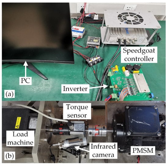
Figure 3.
PMSM test rig. (a) Inverter and Speedgoat controller. (b) PMSM and load machine.

Table 1.
Design parameters of PMSM.
Table 2.
Design parameters of employed VSI.
4.2. Experimental Tests of Zero-Voltage Injection-Based Approach
The results of PMSM operation with injection of zero-voltage perturbation at N = 5 are shown in Figure 4. It can be seen that the total time of applying the method of injection is set to 200 ms from Figure 4a,b of which influences on the average value of rotor speed and currents are negligible. This can be attributed to the short time injection of zero-voltage perturbation and quite high injection frequency, of which the impact on the traction drive system with a large time constant can be ignored. Since the zero-voltage perturbation is injected every 5 switching cycles (N = 5) from t = 1.0 s to t = 1.2 s, the total time of applying and not applying the zero-voltage perturbation is 40 ms and 160 ms, respectively. Figure 4c shows the dq-axis command voltage of total 200 ms of applying the method, and Figure 4d shows the q-axis command voltage within 10 cycles of PWM switching, in which the average value of command voltage will be raised up during the injection. This can be explained that during the injection from t = 1.0 s to t = 1.2 s, one-fifth of the control cycle is set to zero voltage, and in order to keep the system state unchanged, the command voltage will be raised up by the current-loop PI controller during the rest time of the control cycle.
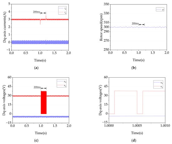
Figure 4.
Waveforms of PMSM with and without injection of zero-voltage perturbation (N = 5, id = 0, iq =3 A, 300 rpm). (a) Dq-axis currents; (b) rotor speed; (c) Dq-axis command voltages within 2 s; (d) Dq-axis command voltages within 10 cycles of PWM switching. −15.
Figure 5 shows the measured currents and rotor speed with the injection of zero-voltage perturbation (N = 5) under variable speed control, which also confirms that the injection of zero-voltage perturbation has a quite negligible influence on the current.
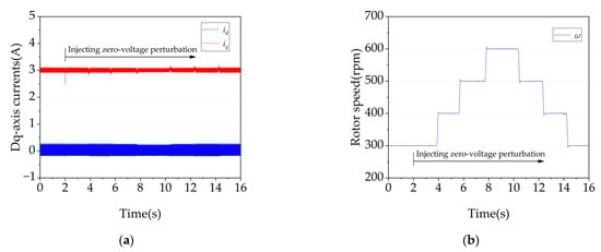
Figure 5.
PMSM waveforms under variable speed control (id = 0, iq = 3 A). (a) Dq−axis currents; (b) rotor speed.
As shown in Figure 6, the command voltage is a function related to the rotor speed during the injection of zero-voltage perturbation. The relationship between the q-axis command voltage and rotor speed is approximately linear, regardless of the value of N (total number of PWM switching cycles included in one control cycle). Therefore, it confirms the correctness of (13), and the rotor flux linkage can also be obtained according to the slope.
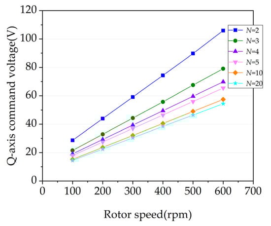
Figure 6.
Measured q-axis command voltage with respect to rotor speed (id = 0, iq = 3 A).
Figure 7 shows the estimated rotor flux linkage of the position-offset-based parameter estimation (POPE) method in [25] and the proposed method at different values of N. For the POPE method, it can accurately estimate the rotor flux linkage, which is described in detail in reference [25]. It can be seen that the online estimated rotor flux linkage by the POPE method is around 0.242 Wb. For the proposed method, the online estimated rotor flux linkage is also around 0.242 Wb. Compared with the nominal rotor flux linkage, the estimation error by the proposed method is within 1.13–1.72%. Therefore, both the proposed method and the POPE method have good performance in estimation of rotor flux linkage. However, according to Figure 4c, the proposed method will raise the average value of the q-axis command voltage; so, it will reduce the utilization of DC bus voltage of VSI. This is described in detail in Section 5.
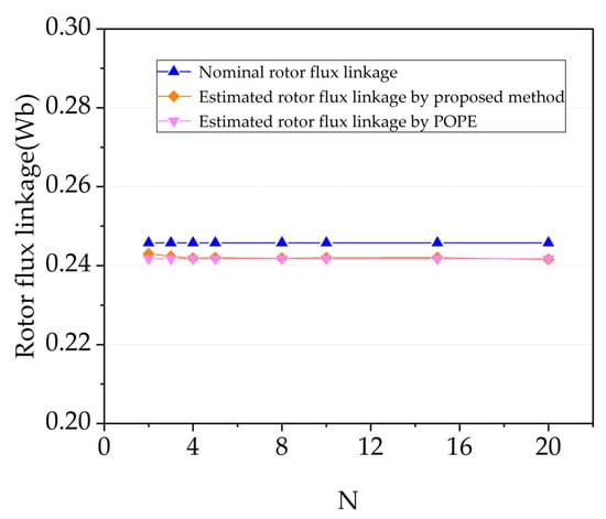
Figure 7.
Nominal and estimated rotor flux linkage of the proposed and POPE method at different values of N.
To investigate the influence of variation of winding resistance on the estimation of rotor flux linkage, the three resistors are connected in series with the three phase windings of PMSM. Each resistor is Rs = 2.2 Ω, and the test result after the addition of resistors with injection of zero-voltage perturbation at N = 5 is shown in Figure 8. It can be seen that the relationship between the q-axis command voltage and rotor speed is also approximately linear after the addition of resistors, and the two curves of q-axis command voltage with respect to rotor speed are almost parallel. Furthermore, the estimated rotor flux linkages are 0.2419 Wb and 0.2412 Wb before and after the addition of resistors, which is shown in Table 3. Thus, the variation of winding resistance has almost no influence on the estimation of rotor flux linkage.
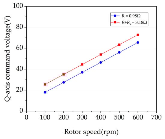
Figure 8.
Measured q-axis command voltage with respect to rotor speed (N = 5, id = 0, iq = 3 A).
Table 3.
Estimated rotor flux linkage value under different winding resistances.
To confirm the accuracy of the proposed method at higher operating temperatures, a comparison experiment under different PM temperatures is designed and conducted as follows:
- The PMSM is drawn by a induction machine and then is heated by connecting the external three-phase winding.
- The rotor speed of PMSM will be fixed to 600 rpm by the induction motor, and the corresponding line back EMF of PMSM under no-load condition will be measured. The rotor flux linkage under no-load condition can be calculated from these measured line back EMF.
- The PMSM will be loaded and the rotor flux linkage under loaded condition will be estimated by the proposed method N = 5.
- Repeat 1–3 under different PM temperatures.
The PM temperature is measured in real time by a high-precision infrared thermal imager (type model: optris Xi400 from Optris GmbH of Berlin, Germany), which is shown in Figure 9. The experimental results of steps 2 and 3 are plotted in Figure 9, which show that the proposed method can accurately track the variation of rotor flux linkage at different PM temperatures. As can be seen from Figure 10, the estimated rotor flux linkage varies from 0.2419 Wb to 0.2336 Wb with the increase of PM temperature.
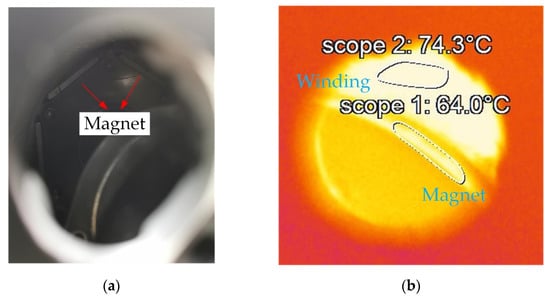
Figure 9.
PM temperature measurement. (a) Observation hole in end cover of PMSM; (b) thermal image captured by a high-precision infrared thermal imager.
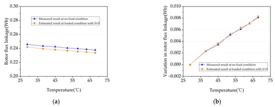
Figure 10.
Comparison between estimated and measured rotor flux linkage under different PM temperatures. (a) Estimated/measured rotor flux linkage; (b) variation in the rotor flux linkage.
4.3. Estimation under Free-Running Condition
Figure 11 shows the free running test starting from different initial speeds, which settle down to zero finally. The duration from the initial speed to zero is defined as the time of free-running. It is worth noting that a higher initial speed of PMSM will result in a longer settling time. The data lengths Data 3 and Data 4 for the estimation of rotor flux linkage are both set to 0.3 s at different initial speeds. However, as can be seen from Figure 11a, the duration of free-running is less than 1 s at 100 rpm. During a period of time when the rotor speed is close to zero, the rotor speed oscillates greatly, which leads to the possibility of invalid data. Hence, on condition that the duration of free-running is too short, it will become difficult to obtain enough data for the estimation of rotor flux linkage.
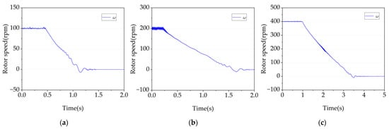
Figure 11.
PMSM waveforms at free-running condition with different initial speeds. (a) 100 rpm. (b) 200 rpm. (c) 400 rpm.
Figure 12 shows the estimated rotor flux linkage by using (19) at different initial rotor speeds of free-running. It can be seen that the online-estimated rotor flux linkage ranges from 0.2938 Wb at 100 rpm to 0.2425 Wb at 1000 rpm. Thus, compared with the nominal rotor flux linkage, the estimated error is 0.53–19.53%. For the tested PMSM, the estimated rotor flux linkage and its estimation error are 0.2541 Wb and 3.38%, respectively, if the initial speed is 200 rpm. Hence, when the initial speed of the PMSM is greater than 200 rpm, the proposed estimation of rotor flux linkage under free-running condition will be of high accuracy.
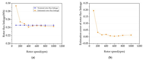
Figure 12.
Estimated rotor flux linkage and its estimation error with respect to different initial rotor speeds of free-running. (a) Nominal and estimated rotor flux linkage; (b) estimation error of rotor flux linkage.
5. Discussion
It is widely known that the EV motor needs to be operated by means of flux-weakening control to improve its operation speed due to the limitation of output voltage of VSI. However, from the experimental results in Section 4.2, it can be seen that the zero-voltage perturbation-based method will raise the average value of the q-axis command voltage. When the EV motor is in flux-weakening control, there may be no excess voltage to apply the proposed method due to the limitation of the output voltage of VSI. Therefore, how to apply the proposed method in flux-weakening control is the focus of future research.
6. Conclusions
In this paper, a method for real-time estimation of PMSM rotor flux linkage under both steady state and free-running conditions is proposed, of which the accuracy will not be affected by the VSI nonlinearity in theory. The effectiveness of the proposed method is verified on a down-sized prototype PMSM developed for EV applications, and it is found that the estimation error at steady state is within 1.13–1.72% while it becomes less than 3.38% if the machine works under free-running condition. Further analysis also shows that the proposed method can be used irrespective of the influence of VSI nonlinearity while the estimation under free-running condition needs a large enough initial rotor speed (>200 rpm) to achieve high signal versus noise.
Author Contributions
Conceptualization, B.W. and K.L.; methodology, B.W. and K.L.; software, B.W., J.Z. and S.Z.; validation, B.W.; formal analysis, B.W. and K.L.; investigation, W.H.; resources, K.L., W.H. and Y.C.; data curation, B.W.; writing—original draft preparation, B.W.; writing—review and editing, B.W., Y.C., C.H., Q.H. and K.L.; funding acquisition, K.L. All authors have read and agreed to the published version of the manuscript.
Funding
This research was supported by the National Natural Science Foundation of China (No. 51877075), the Hunan High-level Talents Gathering Project-Innovative talents Project (No. S2019RSCXRC0094), and the APC was funded by Kan Liu.
Data Availability Statement
Not applicable.
Conflicts of Interest
The authors declare no conflict of interest.
Abbreviations
| Ld, Lq | dq-axis inductances (H) |
| R | Stator winding resistance (Ω) |
| λf | Rotor flux linkage (Wb) |
| ω | Electrical angular speed (rad/s) |
| θ | Electrical angle (rad) |
| γ | Angles between current vector and q-axis (rad) |
| , | Actual dq-axis currents (A) |
| , | Command dq-axis currents (A) |
| , | Actual dq-axis voltages (V) |
| , | Command dq-axis voltages (V) |
| Dd, Dq | Functions of θ and γ |
| Vdead | Distorted voltage due to inverter nonlinearity (V) |
| Ts | PWM switching period (S) |
| N | Total number of PWM switching cycles included in one control cycle |
References
- Zhu, Z.Q.; Howe, D. Electrical machines and drives for electric, hybrid, and fuel cell vehicles. Proc. IEEE. 2007, 95, 746–765. [Google Scholar] [CrossRef]
- Sarlioglu, B.; Morris, C.T.; Han, D.; Li, S. Driving toward accessibility: A review of technological improvements for electric machines, power electronics, and batteries for electric and hybrid vehicles. IEEE Ind. Appl. Mag. 2017, 23, 14–25. [Google Scholar] [CrossRef]
- Reigosa, D.; Fernandez, D.; Yoshida, H.; Kato, T.; Briz, F. Permanent-magnet temperature estimation in PMSMs using pulsating high-frequency current injection. IEEE Trans. Ind. Appl. 2015, 51, 3159–3168. [Google Scholar] [CrossRef]
- Feng, G.; Lai, C.; Kar, N. Expectation-maximization particle-filter- and Kalman-filter-based permanent magnet temperature estimation for PMSM condition monitoring using high-frequency signal injection. IEEE Trans. Ind. Informat. 2017, 13, 1261–1270. [Google Scholar] [CrossRef]
- Li, S.; Sarlioglu, B.; Jurkovic, S.; Patel, N.R.; Savagian, P. Analysis of temperature effects on performance of interior permanent magnet machines for high variable temperature applications. IEEE Trans. Ind. Appl. 2017, 53, 4923–4933. [Google Scholar] [CrossRef]
- Chen, X.; Wang, J.; Griffo, A. A high-fidelity and computationally efficient electro-thermally coupled model for interior permanent magnet machines in electric vehicle traction applications. IEEE Trans. Transp. Electrific. 2015, 1, 336–347. [Google Scholar] [CrossRef]
- Lai, C.; Feng, G.; Mukherjee, K.; Loukanov, V.; Kar, N.C. Torque ripple modeling and minimization for interior PMSM considering magnetic saturation. IEEE Trans. Power Electron. 2018, 33, 2417–2429. [Google Scholar] [CrossRef]
- Morimoto, S.; Sanada, M.; Takeda, Y. Mechanical sensorless drives of IPMSM with online parameter identification. IEEE Trans. Ind. Appl. 2006, 42, 1241–1248. [Google Scholar] [CrossRef]
- Inoue, Y.; Kawaguchi, Y.; Morimoto, S.; Sanada, M. Performance improvement of sensorless IPMSM drives in a low-speed region using online parameter identification. IEEE Trans. Ind. Appl. 2011, 47, 798–804. [Google Scholar] [CrossRef]
- Liu, K.; Zhang, Q.; Chen, J.; Zhu, Z.Q.; Zhang, J. Online multiparameter estimation of nonsalient-pole PM Synchronous machines with temperature variation tracking. IEEE Trans. Ind. Electron. 2011, 58, 1776–1788. [Google Scholar] [CrossRef] [Green Version]
- Kim, H.; Youn, M.; Cho, K.; Kim, H. Nonlinearity estimation and compensation of PWM VSI for PMSM under resistance and flux linkage uncertainty. IEEE Trans. Control. Syst. Technol. 2006, 14, 589–601. [Google Scholar]
- Boileau, T.; Leboeuf, N.; Nahid, B.; Meibody, F. Online identification of PMSM parameters: Parameter identifiability and estimator comparative study. IEEE Trans. Ind. Appl. 2011, 47, 1944–1957. [Google Scholar] [CrossRef]
- Feng, G.; Lai, C.; Kar, N.C. A novel current injection-based online parameter estimation method for PMSMs considering magnetic saturation. IEEE Trans. Magn. 2016, 52, 1–4. [Google Scholar] [CrossRef]
- Underwood, S.; Husain, I. On-line parameter estimation and adaptive control of permanent magnet synchronous machines. IEEE Trans. Ind. Electron. 2010, 57, 2435–2443. [Google Scholar] [CrossRef]
- Shi, Y.; Sun, K.; Huang, L.; Li, Y. Online identification of permanent magnet flux based on extended Kalman filter for IPMSM drive with position sensorless control. IEEE Trans. Ind. Electron. 2012, 59, 4169–4178. [Google Scholar] [CrossRef]
- Dang, D.Q.; Rafaq, M.S.; Choi, H.H.; Jung, J.W. Online parameter estimation technique for adaptive control applications of interior PM synchronous motor drives. IEEE Trans. Ind. Electron. 2016, 63, 1438–1449. [Google Scholar] [CrossRef]
- Rafaq, M.S.; Mwasilu, F.; Kim, J.; Choi, H.H.; Jung, J.W. Online parameter identification for model-based sensorless control of interior permanent magnet synchronous machine. IEEE Trans. Power Electron. 2017, 32, 4631–4643. [Google Scholar] [CrossRef]
- Xiao, X.; Chen, C.M.; Zhang, M. Dynamic permanent magnet flux estimation of permanent magnet synchronous machines. IEEE Trans. Appl. Supercond. 2010, 20, 1085–1088. [Google Scholar] [CrossRef]
- Hamida, M.A.; Leon, J.D.; Glumineau, A.; Boisliveau, R. An adaptive interconnected observer for sensorless control of PM synchronous motors with online parameter identification. IEEE Trans. Ind. Electron. 2013, 60, 739–748. [Google Scholar] [CrossRef]
- Gatto, G.; Marongiu, I.; Serpi, A. Discrete-time parameters identifi-cation of a surface-mounted permanent magnet synchronous machine. IEEE Trans. Ind. Electron. 2013, 60, 4869–4880. [Google Scholar] [CrossRef]
- Wilson, S.D.; Stewart, P.G.; Taylor, B.P. Methods of resistance estimation in permanent magnet synchronous motors for real-time thermal management. IEEE Trans. Energy Convers. 2010, 25, 698–707. [Google Scholar] [CrossRef] [Green Version]
- Feng, G.; Lai, C.; Mukherjee, K.; Kar, N.C. Current injection-based online parameter and VSI nonlinearity estimation for PMSM drives using current and voltage dc components. IEEE Trans. Transp. Electrific. 2016, 2, 119–128. [Google Scholar] [CrossRef]
- Xie, G.; Lu, K.; Dwivedi, S.K.; Riber, R.J.; Wu, W. Permanent magnet flux online estimation based on zero-voltage vector injection method. IEEE Trans. Power Electron. 2015, 30, 6506–6509. [Google Scholar] [CrossRef]
- Feng, G.; Lai, C.; Mukherjee, K.; Kar, N.C. Online PMSM magnet flux-linkage estimation for rotor magnet condition monitoring using measured speed harmonics. IEEE Trans. Ind. Appl. 2017, 53, 2786–2794. [Google Scholar] [CrossRef]
- Liu, K.; Zhu, Z.Q. Position-offset-based parameter estimation using the adaline NN for condition monitoring of permanent magnet synchronous machines. IEEE Trans. Ind. Electron. 2015, 62, 2372–2383. [Google Scholar] [CrossRef]
- Liu, K.; Zhu, Z.Q. Online estimation of the rotor flux linkage and voltage source inverter nonlinearity in permanent magnet synchronous machine drives. IEEE Trans. Power Electron. 2014, 29, 418–427. [Google Scholar] [CrossRef] [Green Version]
- Zhou, S.; Liu, K.; Hu, W.; Chen, Y.; Zhang, D.; Huang, Q.; Tong, Q.; Zhang, Q. Harmonic-separation-based direct extraction and compensation of inverter nonlinearity for state observation control of PMSM. IEEE Access. 2021, 9, 142028–142045. [Google Scholar] [CrossRef]
- Park, D.; Kim, K. Parameter-independent online compensation scheme for dead time and inverter nonlinearity in IPMSM drive through waveform analysis. IEEE Trans. Ind. Electron. 2014, 61, 701–707. [Google Scholar] [CrossRef]
- Deng, W.; Xia, C.; Yan, Y.; Geng, Q.; Shi, T. Online multiparameter identification of surface-mounted PMSM considering inverter disturbance voltage. IEEE Trans. Energy Convers. 2017, 32, 202–212. [Google Scholar] [CrossRef]
- Feng, G.; Lai, C.; Tjong, J.; Kar, N.C. Noninvasive Kalman filter based permanent magnet temperature estimation for permanent magnet synchronous machines. IEEE Trans. Power Electron. 2018, 33, 10673–10682. [Google Scholar] [CrossRef]
Publisher’s Note: MDPI stays neutral with regard to jurisdictional claims in published maps and institutional affiliations. |
© 2022 by the authors. Licensee MDPI, Basel, Switzerland. This article is an open access article distributed under the terms and conditions of the Creative Commons Attribution (CC BY) license (https://creativecommons.org/licenses/by/4.0/).