Abstract
This paper overviews the recent advances in flux-adjustable permanent magnet (PM) machines for traction applications. The flux-adjustable PM machines benefit from the synergies of the high torque density and high efficiency in conventional PM machines as well as the controllable air-gap field in wound-field machines, which are attractive for the traction applications requiring enhanced capabilities of speed regulation and uncontrolled voltage mitigation. In general, three solutions have been presented, namely the hybrid excited (HE), the mechanically regulated (MR), and the variable flux memory (VFM) machines. Numerous innovations were proposed on these topics during the last two decades, while each machine topology has its own merits and demerits. The purpose of this paper is to review the development history and trend of the flux-adjustable PM machines, with particular reference to their topologies, working mechanism, and electromagnetic performance.
1. Introduction
Due to high energy product permanent magnet (PM) materials, PM machines are widely investigated and utilized for their inherent high torque/power density and high efficiency and are treated as competitive candidates in traction applications [1]. Nevertheless, the air-gap field of PM machines is relatively constant because of the high energy product PMs. As a result, the high induced back-electromotive force (EMF) limits the constant-power speed range (CPSR) in the modern drive system with the inverter limitation in current and voltage ratings, which are critical in variable-speed applications such as electric vehicles. Although the negative d-axis armature current can be applied according to the vector control theory to realize the flux-weakening and hence extend the speed range, the reactive current inevitably degrades the machine efficiency, power density, and power factor [2,3,4]. Moreover, since the back-EMF is proportional to the rotation speed, the terminal induced voltage is significant in high-speed operation, which threatens the drive system if the applied flux-weakening armature current fails. This uncontrolled induced voltage in PM machines is fatal in the generating mode [5,6]. In addition, the risk of the unintentional de-magnetization (UD) occurs during the flux-weakening control as the negative d-axis armature reaction field reversely flows through the PMs.
Extensive studies have been conducted to overcome the aforementioned drawbacks of the conventional PM machines, and three solutions can be categorized in terms of the innovative machine topologies.
- (1)
- The first type can be referred to as hybrid excited (HE) machines. HE machines possess both PM and field coils (FC) as excitation sources and thus integrate the advantages of PM machines and wound-field machines. The field current in the FCs can be flexibly regulated to realize the flux-enhancing for torque boosting or the flux-weakening for speed extending [7].
- (2)
- The second solution is classified as mechanically regulated (MR) machines [8]. Additional mechanical actuators are assembled into the PM machines to mechanically change the flux flowing paths and therefore the resultant flux-linkage of the armature coils. The mechanical devices either move the PMs or the ferromagnetic material to change the magnetic structure of the PM machines.
- (3)
- The third is variable flux memory (VFM) machines [9], featuring the intentional employment of the low coercive force (LCF) PM. With the magnetization magneto-motive force (MMF) generated by a current pulse, the residual flux density of the LCF PM can be intentionally adjusted and memorized after the current is released. As a result, the air-gap flux density of VFM machines is altered. During low-speed operations, the LCF PMs are re-magnetized into the maximum magnetization state (MS), leading to the high air-gap field and hence high torque output. On the other hand, the LCF PMs are de-magnetized to the low MS in high-speed conditions for the weakened air-gap field, which indicates the extended CPSR as well as the reduced iron loss.
A variety of machine topologies belonging to the aforementioned three types were proposed, and they all feature the capability to adjust the open-circuit flux-linkage in armature coils. Figure 1 illustrates the classification of all the feasible flux-adjustable PM machines according to their structures, which are detailed in the following sections. In Section 2, HE machines are reviewed, with particular reference to the locations of the PMs and FCs, as well as the magnetic couplings between these two excitation sources. In addition, the MR machines are outlined in Section 3, and the methods of PM movement and iron-core movement are summarized in Section 4. VFM machines are also systematically overviewed. The PM locations and the magnetic couplings between the PMs are highlighted after the brief introduction of their operating principle. The design considerations for traction applications and the key performance such as torque output and flux regulation capability of these machines are extensively introduced.
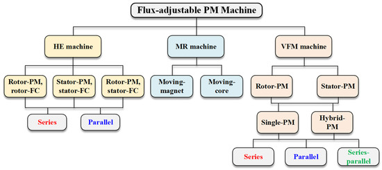
Figure 1.
Classification of the flux-adjustable PM machines.
2. HE Machines
The concept of HE machines was proposed in the middle of the 20th Century [7]. In HE machines, the PMs and FCs contribute to the air-gap field simultaneously, where the PM flux works as a constant component while the FC flux functions as the variable component, and thus the air-gap field is controllable. As a consequence, the ratio between the PM flux and the FC flux as an additional degree of freedom in the machine design and control is obtained in HE machines. During the low-speed operation, the positive field currents are adopted to enhance the air-gap flux and therefore improve the torque output. Alternatively, during the high-speed operation, the negative field currents can be applied to realize the flux-weakening, which counters the PM flux, reduces the induced back-EMF, and thus extends the CPSR. As the field current in the FCs is independent of the armature windings, it is easily controlled and has little effect on the armature current capacity. Furthermore, the HE machines potentially reduce the usage volume of high energy product PM materials, which compromises the cost.
Since the two excitation sources coexist, the HE machine topologies are diverse. In terms of the locations of the PMs and FCs, HE machines can be categorized into three groups [10,11,12,13], which are also included in Figure 1.
- Rotor-excited HE machines with both PMs and FCs on the rotor. In this case, slip rings and brushes are required to feed the field current into the rotor-located FCs.
- Mixed-excited HE machines with PMs on the rotor and FCs on the stator.
- Stator-excited HE machines with both PMs and FCs on the stator.
Moreover, in terms of the magnetic couplings between the PM flux and the FC flux, HE machines can be classified into two categories [11,14,15,16].
- Series HE machines where the flux generated by the FCs flows through the PMs, i.e., they share the same magnetic path.
- Parallel HE machines where the PM flux and the FC flux have distinct trajectories.
2.1. Location of PMs and FCs
The locations of the PMs and FCs basically determine the machine topology and have an essential effect on the machine performance. The conventional rotor-PM synchronous machines and the novel stator-PM synchronous machines both can be transformed into HE machines.
2.1.1. Rotor-Excited HE
Based on the classic rotor-PM synchronous machine, the rotor-excited HE machine can be directly developed for enhancing flux controllability. The PMs and FCs are both located on the rotor, while the armature coils are on the stator [17]. As illustrated in Figure 2a, the FCs are wound around the rotor poles that are also surface-mounted with the PMs, while a conventional AC stator is inherited. This topology is the integration of a PM synchronous machine and a wound-field synchronous machine. The air-gap flux density can be effectively enhanced or weakened by the field current [18,19]. The different flowing paths of the FC and PM fluxes can also be realized by adjusting the rotor pole arrangement [20], as shown in Figure 2b. The series and parallel magnetic couplings are obtained, contributing to distinct electromagnetic characteristics, which are detailed in the following section.
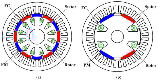
Figure 2.
Cross sections of rotor-excited HE machines. (a) Rotor-excited HE machines with series coupling [17]. (b) Rotor-excited HE machines with parallel coupling [20].
In addition, the rotor with consequent-pole surface-mounted PM can be reformed with FCs, which is helpful in reducing the equivalent reluctance for the FC flux and thus enhancing the flux regulation capability [19,21,22], and meanwhile, the PM usage volume can be reduced. Furthermore, the PM allocations and shapes can be flexibly changed. The FCs can be applied into the interior-PM rotor as well, where the iron bridges on the rotor provide the flowing paths for the FC flux. The spoke-type interior-PM rotor is presented in [23], with which the flux-focusing effect of the PM field is achieved and hence the torque density can be boosted. Alternatively, the PMs can be inserted into the slot-openings of the rotor in the conventional wound-field synchronous machines [24]. The working principle of the slot-opening-located HE machines is slightly different from other HE machines. The PM flux is short-circuited in the open-circuit condition and has no effect on the open-circuit back-EMF, while it influences the armature reaction field based on the magnetic saturation.
Since the FCs are allocated on the rotary component, slip rings and brushes are required to conduct the field current, which inevitably reduces the robustness and increases the machine maintenance cost.
2.1.2. Mixed-Excited HE
In order to eliminate the sliding contacts, the toroid FCs are employed on the stationary component, while the PMs are still located on the rotor [25,26]. The mixed-excited topology is presented. This structure has both radial and axial fluxes, in which the PMs provide the radial flux as a constant component, while the flux due to the toroid FC flows through the axial path. Consequently, the 3D flux is present. As illustrated in Figure 3, a toroid FC is placed on the center of the stator yoke, and the radially magnetized consequent-pole surface-mounted PMs are on the rotor. The rotor is axially segmented into two parts to accommodate the center-based FC, while the consequent-pole structure is adopted to reduce the magnetic reluctance for the FC flux and hence enhance the flux controllability. By injecting different field currents, the magnetization of iron poles on the rotor can be varied, and the air-gap flux density is thus controlled [27,28].
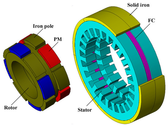
Figure 3.
Configuration of a mixed-excited HE machine with a toroid FW in stator yoke [27].
In addition to the topologies with the center-based FC, more mixed-excited HE machines have been developed. The FCs can be accommodated on the machine axial extremities, either on one side [29,30,31], as shown in Figure 4a, or on both sides [12,14,32], as shown in Figure 4b. As a result, more FC coils can be applied with the additional stationary magnetic end-parts. Moreover, based on the end-based FC, the axially magnetized PM can be employed on the rotor, which is sandwiched between the dual-stack half-pitch skewed salient rotor [33,34], as shown in Figure 5, or claw pole rotor [35,36], as shown in Figure 6.
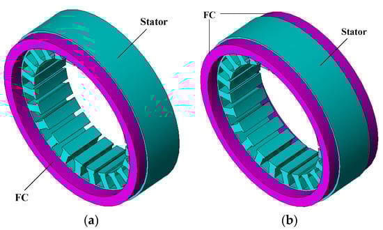
Figure 4.
Illustration of toroid FCs located on the stator extremities in mixed-exited HE. (a) FC on the stator, one extremity. (b) FCs on the stator, both extremities.
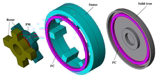
Figure 5.
Configuration of the mixed-excited HE machine with skewed dual-stack rotor [34].
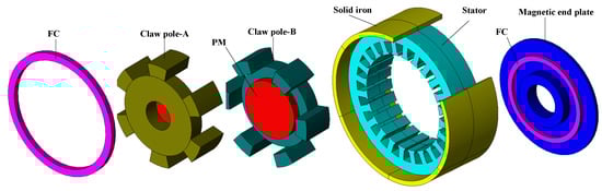
Figure 6.
Configuration of the mixed-excited HE machine with claw pole rotor [36].
It can be found that the extra axial air-gap always exists in the mixed-excited HE machines, and hence the 3D flux occurs, which corresponds to both sophisticated structures and significant flux-leakage that sacrifices the torque density. An alternative mixed-excited HE machine with solely radial field is shown in Figure 7, where the consequent-pole surface-mounted PMs are allocated on the rotor while the FCs and armature coils are located on the stator [37]. In this machine, the FCs are effective in weakening the air-gap field via magnetic saturation, but they cannot easily boost the air-gap field. As a result, the flux regulation range is limited.
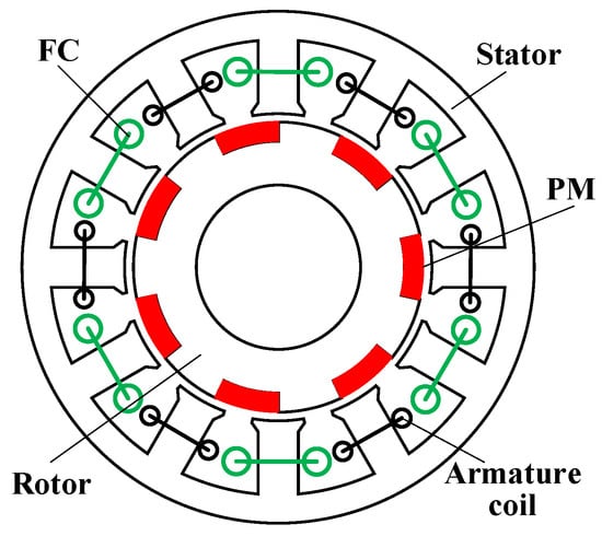
Figure 7.
Configuration of the mixed-excited HE machine with solely radial field [37].
2.1.3. Stator-Excited HE
Stator-excited HE machines originate from the stator-PM machines which locate PMs on the stator and employ the salient rotor free from copper or PM. In stator-excited HE machines, the PMs and FCs, together with armature windings, are all placed on the stator [38]. As a consequence, the brushes are avoided, and the temperature rises of the PMs and coils are easily managed as they are on the stationary components.
Originating from the very first stator-excited HE machine with the unipolar phase flux-linkages [39,40], a typical three-phase 12-stator-slot/8-rotor-pole stator-excited HE machine [41] is illustrated in Figure 8a. Tangentially magnetized PMs are inserted into the stator yoke. The FCs are also located on the stator, together with the three-phase concentrated non-overlapping armature windings. The number of the PMs is one-third of the number of armature coils for a three-phase machine. In this machine, the air-gap field is contributed simultaneously by the PMs and FCs. The flux-linkage of the armature coils can thus be enhanced or weakened by adjusting the field currents. It can be noted that the asymmetric flux path occurs for each armature coil, while the phase flux-linkage is unipolar in this machine [42,43], which compromises torque density [44]. Meanwhile, since the unipolar phase flux-linkages are employed in the machine, the proposed HE machines suffer limited torque density and high torque ripples.
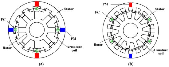
Figure 8.
Cross section of stator-excited HE machines with unipolar flux (a) with series coupling [41] and (b) with parallel coupling [51].
Furthermore, stator-excited HE machines with bipolar phase flux-linkage can be obtained by offering a symmetrical magnetic path for both the PM flux and FC fluxes [45,46,47], as the instances illustrate in Figure 9. Tangentially magnetized PMs are sandwiched in the stator tooth, and the concentrated FC coils are also wound around the stator tooth, whereas the concentrated non-overlapping armature windings are inherited. As a result, each armature coil is excited by the PM and the FC together, while the PM flux and FC flux are both bipolar, which benefits the torque density and smoothness. The iron bridges close to the PMs can be employed to adjust the magnetic coupling type between the PM and FC fluxes. In addition, the stator-PM machines with surface-mounted PMs on the stator tooth can also be transformed into stator-excited HE machines, and the consequent-pole surface-mounted PMs are helpful in alleviating the reluctance for the FC flux [48,49].
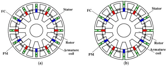
Figure 9.
Cross section of a parallel stator-excited HE machine with bipolar flux (a) with iron bridge for parallel coupling [45] and (b) without iron bridge for series coupling [47].
As the active components including PMs, FCs, and armature coils are all placed on the stator and the rotor simply consists of iron, stator-excited HE machines benefit from the relatively simple structures as well as the absence of brushes and slips. Nevertheless, it should be noted that the major components placed on the stator also result in the space conflict and therefore sacrifice the flux controllability as well as torque density. In order to alleviate the crowded stators and utilize the space close to the rotor region, the concept of the partitioned stator (PS) is proposed [50]. In the PS HE machine shown in Figure 10, a primary stator is used to accommodate the armature windings, while a secondary stator is introduced to place the excitation sources (PMs and FCs), together with a rotor sandwiched between the two stators. The sliding contact is avoided, and only radial flux is present. More importantly, the excitations sources are arranged in the secondary stator, which enhances the space utilization of the machine. In addition, as a separated stator is specifically used for the PMs and FCs, the excitation sources can be flexibly allocated to obtain distinct magnetic couplings.
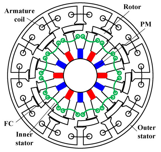
Figure 10.
Cross section of a PS HE machine [50].
2.2. Magnetic Coupling between PMs and FCs
Among the various topologies of HE machines, the magnetic coupling between the PM and FC fluxes features either a series or parallel connection. The two magnetic couplings can be realized in rotor-excited, mixed-excited, and stator-excited HE machines, and they have an important effect on the machine performance.
2.2.1. Series HE
The series HE type can be easily obtained in rotor-excited HE machines, as in Figure 2a, where the FC coils are wound around the PM poles in the surface-mounted PM or interior-PM rotor. Therefore, the flux due to the FCs flows through the PMs.
Stator-excited HE machines can also be realized with series connection in magnetic coupling. In the machines with unipolar flux, as shown in Figure 8a, the FC flux loops through the PM, and the series connection is hence presented. This is actually determined by the stator-slot/rotor-pole number combination and the relative location between the PMs and FCs. Moreover, a series stator-excited HE machine with bipolar flux is shown in Figure 9b [47,52], in which the FC flux must go through the PM in a loop. It can be found that the major difference between this series HE machine and the corresponding parallel HE machine [45], as shown in Figure 9a, is the elimination of the iron bridges which are adjacent to the PMs. By eliminating these iron bridges, the bypass path for the FC flux is removed, which limits the flux controllability but also reduces the short-circuited PM flux and thus improves the torque output. The analysis of the iron bridge effects is included in [45,53].
The series connection can also be seen in Figure 7 as a mixed-excited HE machine, where the FC flux has to go through the PMs [37].
2.2.2. Parallel HE
The parallel HE machine topology can be obtained in the rotor-excited machines by adjusting the rotor pole arrangement, with which the separate paths for the FC flux and PM flux are produced, as illustrated in Figure 2b [20]. A pair of FC poles coexist with the two pairs of PM poles in the rotor, and their fluxes can flow independently. As a result, the PM flux and the FC flux are connected in parallel, and they contribute to the air-gap individually.
The 3D flux mixed-excited HE machines usually feature parallel connections [14,25,26,27,28,29], where the PM flux only flows through the radial path while the FC flux has specific 3D loops bypassing the PMs. In [33,34,35,36], the PM and FC fluxes both flow through the 3D loops and have independent paths. It can be seen that the 3D flux mixed-excited HE machines normally have sophisticated structures and thus degraded compactness and robustness.
The parallel stator-excited HE machine with unipolar flux is presented in Figure 8b, where an 18-stator-slot/12-rotor-pole structure is illustrated [51]. Compared with the series counterpart in Figure 8a, the major difference is the adjustment of stator-slot/rotor-pole combination and the PM piece number. The stator slot number is increased while the PM piece number is halved, with which the physical distance between the PMs is increased and hence the FC flux can loop without crossing the PMs, resulting parallel coupling. The parallel stator-excited HE machine with bipolar flux can be seen in Figure 9a, and the iron bridges short-circuiting the PMs added to the series HE structure are shown in Figure 9b. As a consequence, the FC flux can bypass the PMs through the iron bridges to obtain a parallel connection.
Further, the dual-stack technique has been used to realize the parallel connection in HE machines, which is applicable to both rotor-excited and stator-excited machines. The dual-stack HE machines comprise the axial integration of a PM synchronous machine and a wound-field synchronous machine, in which the PMs contribute to the air-gap field among one axial stack while the FCs work amongst the other stack. This technique is effective for rotor-excited HE machines [54,55], where a surface-mounted PM machine and a conventional wound-field synchronous machine with FCs on the rotor are combined together, whereas their stators are identical and they share the same armature windings, as shown in Figure 11a. The dual-stack stator-excited HE machine can be obtained as well [56] based on the integration of a stator-PM machine and a wound-field machine with FCs on the stator, in which they can share the same rotor, stator, and armature windings, as shown in Figure 11b. It should be noted, however, that the dual-stack machines suffer the additional gap between the two stacks for winding end-parts, which remarkably degrades the machine compactness and torque density.
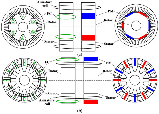
Figure 11.
Configurations of dual stack HE machines with parallel couplings. (a) Dual-stack HE machine with wound-field rotor and PM rotor [54]. (b) Dual-stack HE machine with wound-field stator and PM stator [56].
2.2.3. Comparison of Series and Parallel HE Machines
A multitude of HE topologies can be classified into series or parallel connections, and they exhibit distinct electromagnetic performance. It is of value to have a fair comparison between them. The PS concept provides a unique platform that minimizes the structure difference between the series and parallel counterparts. A pair of PS HE machines are shown in Figure 12, where the identical brushless structures can be seen in the primary stator with 12 armature coils as well as the rotor [57,58]. The only difference is located at the PM arrangement in the secondary rotors. In the series HE machine, as shown in Figure 12a, the PMs and FCs are alternately placed on the 12 stator teeth, and hence the consequent-pole technique is adopted [57]. In contrast, every two pieces of PMs and two FCs are alternately allocated in the parallel HE machine, as shown in Figure 12b, where the PM flux and FC flux loop independently [58]. The flux paths of the two machines are illustrated in Figure 13, where the series coupling and the parallel coupling can be clearly identified. With the identical outline dimension (stack length of 25 mm and outer diameter of 90 mm), PM dimension (height of 3.5 mm and arc of 25.5°), armature windings, and FCs [16], the basic electromagnetic performances of the two machines are compared in Figure 14. Two rotor piece numbers are included (10- and 11-rotor for both series and parallel machines) for comprehensive results. As in Figure 14a, the open-circuit back-EMFs can be more effectively regulated by the field currents in the parallel HE machines, indicating the better flux regulation capability. On the other hand, the series HE machines benefit from higher torque output, as shown in Figure 14b. Therefore, two conclusions are drawn for HE machines with identical dimensions: (1) The parallel HE machines naturally have better flux regulation capabilities due to their independent paths for the PM flux and FC flux. (2) The series HE machines are advantageous in torque capability.
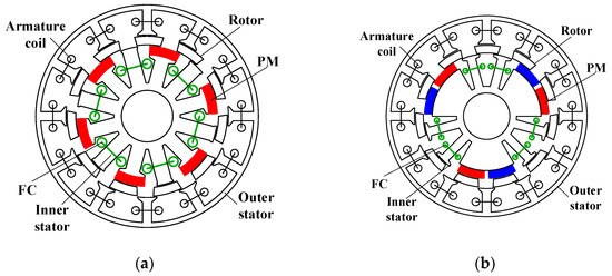
Figure 12.
Cross sections of a pair of series and parallel PS HE machines. (a) Series HE [57]. (b) Parallel HE [58].
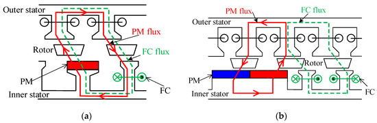
Figure 13.
Illustrations of PM and FC flux paths of series and parallel HE machines. (a) Series HE. (b) Parallel HE.
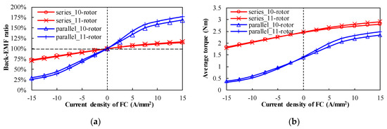
Figure 14.
Flux regulation and torque capabilities of series and parallel HE machines. (a) Variations of back-EMF ratio versus field current. (b) Variations of average torque versus field current.
2.3. Summary
The merits and demerits of all HE machines are summarized in Table 1. In conclusion, slip rings and brushes are required in rotor-excited HE machines. Although sliding contacts are avoided, sophisticated structures of the mixed-excited HE machines result in the remarkable flux-leakage, sacrificed torque density and limited flux regulation. Finally, stator-excited HE machines are free from sliding contacts and benefit from the simplified structures and robust rotors. Although space conflict is severe in the stator due to the accommodation of PMs, FCs, and armature coils, the PS technique is of value in boosting the machine performance. In terms of the series or parallel coupling between the two excitation sources, the parallel type is superior in flux regulation capabilities due to its independent paths for the PM flux and FC flux, while the series type is advantageous in torque capability.

Table 1.
Advantages and disadvantages of various HE machines.
3. MR Machines
The MR machines depend on the mechanical actuators to change either the PM flux or the major magnetic path, resulting in the flux variation of the coil. As shown in Figure 1, the MR machines can be categorized into the moving-PM type and moving-core type according to the object of the mechanical devices.
3.1. Moving-PM
The phase flux-linkages can be adjusted by changing the relative location between the PMs and the armature coils. It is easily achieved in a dual-rotor PM machine, where the mechanical shift between the two rotors can be regulated. Figure 15 presents an axial-field PM machine featuring two disk-type PM rotors [8]. With a particular phase displacement between the two rotors controlled by a mechanical device, the flux-linkage linked by the armature winding is adjusted. A similar method is applied to the radial-field PS machine, where the iron-piece rotor is sandwiched between the outer stator with armature coils and the inner stator with PMs [59]. The mechanical shift between the two co-axis stators is adjusted via the mechanical actuator, which results in the variation of the magnetic circuit and thus the change of the phase flux-linkage.
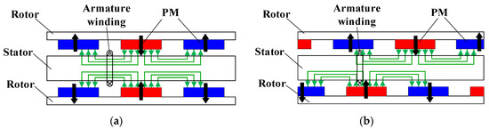
Figure 15.
Flux mechanically controllable by shifting PM rotors [8]. (a) Flux-enhancing state. (b) Flux-weakening state.
Another MR solution is to employ the cylindrical PMs that can be mechanically rotated. An interior-PM machine following this principle is proposed in [60]. The cylindrical PMs are mechanically rotated by a servomotor, and the PM flux flowing through the air-gap is changed with different PM rotation angles. The schema of the flux path in the flux-enhancing state is shown in Figure 16a, while that in the flux-weakening state after the PMs are mechanically rotated by 90° is illustrated in Figure 16b. It is obvious that the effective PM flux is regulated by changing the magnetic circuit. A similar design with a 48-stator-slot/8-rotor-pole interior-PM configuration is proposed in [61]. Each rotor pole is composed of one I-type PM and two cylindrical PMs. The cylindrical PMs can be mechanically rotated with a certain degree, and therefore the main flux path as well as the air-gap field is changed. The concept of moving the PMs can also be applied into the stator-PM synchronous machines. A classic stator-PM machine is reformed with an additional cylindrical PM close to the original rectangle PMs [62]. The original rectangular PM and the cylindrical PM are in parallel connection in the flux-enhancing state, as shown in Figure 17a. If the cylindrical PMs are mechanically rotated by 180°, the flux of the rectangular PMs is partially short-circuited, leading to a flux-weakening state, as shown in Figure 17b.
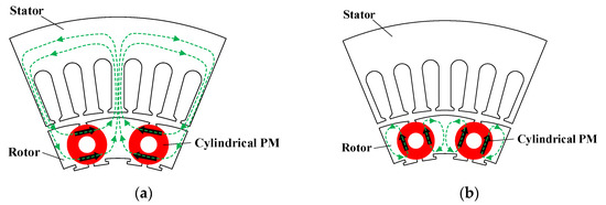
Figure 16.
Illustration of operating principle of the rotor-PM MR machine with cylindrical PMs [60]. (a) Flux-enhancing state. (b) Flux-weakening state.
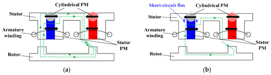
Figure 17.
Illustration of operating principle of the stator-PM MR machine with cylindrical PMs [62]. (a) Flux-enhancing state. (b) Flux-weakening state.
3.2. Moving-Core
The mechanical regulation can be applied to the iron core while the PMs are kept stationary, which can also adjust the flux-linkage of the armature coils. An axial-field surface-mounted PM machine featuring additional cores enclosing end windings is proposed in [63]. By introducing the C-shape cores into each end winding, the manipulation of the synchronous inductance is carried out. A method to adjust the PM flux flowing through the air-gap by utilizing a mechanical device to short-circuit the PM flux at the two axial ends is also presented [64]. The end leakage-flux is intentionally regulated by adjusting the solid iron plates at the two ends. However, the flux variation range is reported to be around 14%, which may be inadequate as only the end leakage-flux is employed.
Alternatively, as shown in Figure 18, a spoke-type PM machine with a radial arc-type displaceable device connected to the shaft via springs is presented [65]. The magnetic arc-type device is retained close to the shaft at low-speed operation, referring to the flux-enhancing state, as shown in Figure 18a. When the rotation speed increases, the arc-type device automatically moves towards the rotor core due to the centrifugal force, resulting in the increased short-circuited PM flux and hence the flux-weakening state, as shown in Figure 18b. As a result, the mechanical flux-weakening effect is automatically achieved at high speed, which can meet the requirement of the extended speed range for traction applications.
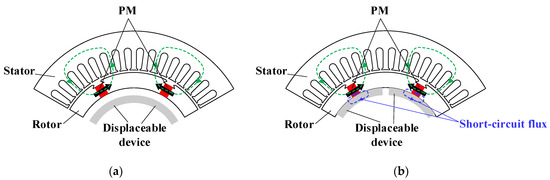
Figure 18.
Illustration of the mechanism of the arc-type displaceable device [65]. (a) Flux-enhancing state. (b) Flux-weakening state.
In [66], a mechanically movable flux adjuster consisting of iron pieces is designed to be located at the stator exterior of the classic stator-PM machine, which is close to the PMs and thus can partially short-circuit the PM flux, as shown in Figure 19.
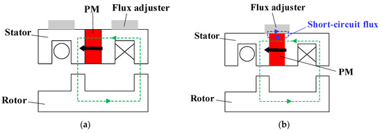
Figure 19.
Illustration of the mechanism of the flux adjuster [66]. (a) Flux-enhancing state. (b) Flux-weakening state.
3.3. Summary
In summary, the MR machines are advantageous in flux regulation, but the additional passive or active mechanical devices are inevitably required to intentionally move either the PMs or iron-core, which may degrade the machine robustness and compactness. In addition, the precise actions of the mechanical devices require high-performance sensors, controllers, actuators, and reliable algorithms.
4. VFM Machines
VFM machines can realize the flux adjustment via the current pulse, dissipating negligible copper loss, which makes them more attractive compared with HE machines. In addition, the field is regulated via the electric behavior, and hence mechanical actuator is avoided, which benefits robustness and compactness.
The characteristics of VFM machines rely on the magnetic properties of the LCF PMs, and thus their operating principle is firstly introduced. Afterwards, as shown in Figure 1, VFM machines are divided into the rotor-PM group and the stator-PM group according to the PM locations. Moreover, the single LCF PM solution as well as the hybrid PM solution with both LCF PM and normal high coercive force (HCF) PM are detailed.
4.1. Variable Flux Principle
The variable flux principle in VFM machines can be illustrated by the hysteresis model of LCF PMs, as shown in Figure 20. The blue solid line refers to the major hysteresis loop of the LCF PM, while the black dotted line represents the load line, and the dotted lines D1-R1 and D2-R2 represent the recoil lines. After applying a high negative MMF from a current pulse, the LCF PM working point moves along the major loop to point D2 which is below the knee point. After releasing the excitation, the working point shifts from D2 to P2 along the recoil line. The residual flux of LCF PMs reaches a new level that is lower than the initial value. As a result, the de-magnetization is conducted. In contrast, if a positive MMF pulse is conducted, the LCF PM working point shifts along the loop P2-R2-R1-P1. Afterwards, LCF PMs finally possess a higher residual flux than the previous state. Hence, the MS of LCF PMs can be altered and memorized at different levels, leading to an adjustable air-gap flux density.

Figure 20.
Scheme of the variable flux principle.
The typical de-magnetization curve of various LCF PMs, including AlNiCo, SmCo and (Ce, Nd)-Fe-B PMs, are shown in Figure 21, which is the core consideration for material selection. The typical HCF PM, i.e., NdFeB material, is also included in Figure 21 as a benchmark. Due to the relatively high remanence flux density for boosting torque density while the low coercive force results in an easy MS manipulation, the AlNiCo PM is widely used in VFM machines. However, a high risk of UD occurs in the cases with heavy loads. In contrast, both the residual flux density and coercive force are high in the SmCo PM, leading to more stable working points but higher de/re-magnetization currents. Alternatively, the (Ce, Nd)-Fe-B PM, a newly emerging LCF PM material, has a great potential in VFM machines due to its customizable coercive force and low cost. Nevertheless, the relatively low residual flux density may hinder its utilization in high power density traction applications.
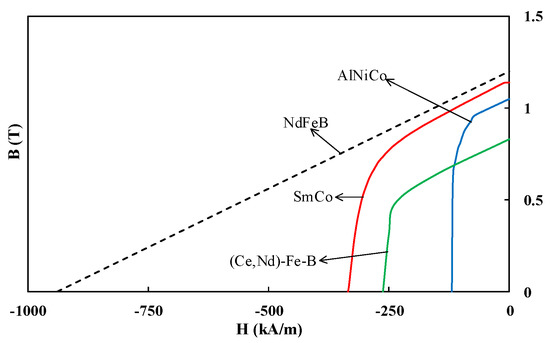
Figure 21.
Typical de-magnetization curves of LCF PMs.
4.2. Rotor-PM VFM Machines
4.2.1. Single-PM
By integrating the merits of the variable rotor flux in the wound rotor machines and zero excitation loss in the PM machines, the VFM machine was firstly proposed by Ostovic [9], as illustrated in Figure 22. It is characterized by a sandwich rotor consisting of tangentially magnetized PMs, soft iron, and a non-magnetic barrier. The flux barriers are designed to block the q-axis flux and thus minimize its influence on the magnetization of LCF PMs. The air-gap field can be smoothly adjusted by a d-axis armature current pulse. VFM machines feature intentional de-/re-magnetization via the negative/positive d-axis currents, while the unintentional de-magnetization caused by the q-axis field should be avoided. The state-of-the-art VFM technology promotes the development of PM machines in the field with the demand of a wide speed range and low copper loss. The influence of the LCF PM shape on the de-magnetization is detailed [67]. Further, a two-step finite element (FE) analysis is proposed to address the non-uniform de-magnetization field generated by the trapezoidal PMs [68]. The de-magnetization characteristic was investigated based on the local hysteresis model [69], and it was found that the complete re-magnetization is more difficult than the de-magnetization due to magnetic saturation.
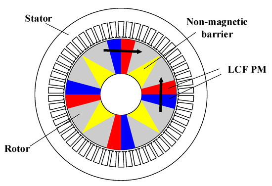
Figure 22.
Topology of the original VFM machine [9].
The original VFM machine proposed by Ostovic suffers from the low torque density due to massive q-axis flux barriers and difficulty in maintaining the MS with heavy load, i.e., UD occurs. The negative reluctance torque is generated with the classic flux-weakening control. To address this problem, Lorenz presented a novel VFM machine based on the flux intensifying interior-PM (FI-IPM) topology [70], as shown in Figure 23. In this machine, the d-axis flux path as well as the significant flux barrier along the q-axis contribute to the inverse saliency, i.e., the d-axis inductance is higher than the q-axis inductance. As a result, the MS of the LCF PMs is stable even in overload conditions since the positive d-axis currents not only generate positive reluctance torques but also help maintain LCF PM MS. Meanwhile, the rotor iron bridges close to the air-gap offer another degree of MS manipulation. The magnetic reluctance of these iron bridges is affected by the q-axis flux, and therefore the leakage flux can be regulated. However, large re-magnetizing current is required due to the severe magnetic saturation on the rotor, and the overall torque density is still remarkably sacrificed due to the significant flux barriers in this VFM machine.
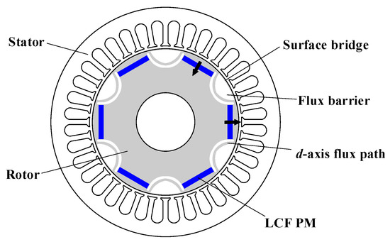
Figure 23.
FI-IPM VFM machine [70].
Another VFM machine characterized by inverse saliency is presented in Figure 24, where the spoke-type AlNiCo PMs are utilized to achieve high air-gap flux density and thus high torque density [71]. An uneven air-gap is adopted to reduce the back-EMF harmonics and hence improve the efficiency. It is claimed that this machine can produce torque density comparable to the conventional PM machines and obtain improved efficiency in the high-speed region. More considerations in rotor design are offered to improve the torque quality and reduce re-magnetizing current amplitudes [72]. It was found that the uneven air-gap design is also effective in reducing torque ripple, which is normally serious in tangentially magnetized PM machines.
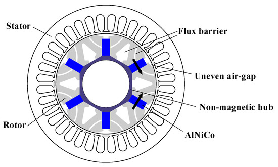
Figure 24.
Spoke-type VFM machine [71].
4.2.2. Parallel
As the energy product of the LCF PMs is lower than that of the classic high energy product PMs, the conventional VFM machines with sole LCF PMs are generally inferior in torque density and cannot easily reach the required torque output in the case of traction applications. Therefore, the concept of the hybrid PM solution is proposed for VFM machines, where the LCF PMs and the HCF PMs coexist to realize both easy flux adjustment as well as high torque density. Furthermore, parallel, series, or series-parallel couplings between the two kinds of PMs can be obtained.
In [73], a parallel-type hybrid PM VFM machine is proposed where the tangential PMs close to the air-gap are NdFeB materials while the radial PMs close to the shaft are AlNiCo materials, as shown in Figure 25. The two kinds of PMs both contribute to the air-gap in the flux-enhancing MS, while the HCF PMs are partially short-circuited through the LCF PMs in the flux-weakening MS. A similar design is presented [74], where the LCF PM is arranged with the radial direction while the HCF PM is allocated in the middle part of the magnetic pole close to the shaft. The MS variation range is further widened in high-speed operation when the LCF PMs are de-magnetized to short-circuit more HCF PM flux.

Figure 25.
U-type parallel hybrid PM VFM machine [73].
In Figure 26 a, a parallel-type hybrid PM VFM machine characterized by V-type HCF PMs and tangential LCF PMs is presented [75]. The specially designed rotor flux barriers can mitigate the cross-coupling between the HCF PM and the LCF PM, resulting in the easier re-magnetization but a slightly more difficult de-magnetization. The NdFeB material is normally used as the HCF PMs, and the selection of LCF PMs is discussed. It is found that a wider MS variation range is achieved with AlNiCo PMs, but their working points are challenge to maintain. In [76], a parallel scheme with the new PM material as the LCF PM, i.e., CeFeB, is proposed, as shown in Figure 26b. Flux barriers are placed on the main flux path to weaken the cross-coupling between the two kinds of PMs.
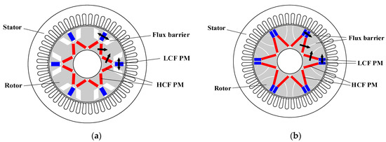
Figure 26.
V-type parallel hybrid PM VFM machines. (a) Flux barriers close to the air-gap [75]. (b) Flux barriers on the main flux path [76].
A delta-type salient pole VFM machine with extended q-axis flux barriers is presented in Figure 27, where the tangential LCF PMs are located at the q-axis position [77]. The double-layer delta-type HCF PMs help LCF PMs to resist the UD caused by the q-axis armature reaction field. Moreover, the extended q-axis flux barriers can effectively reduce the required currents for intentional re-magnetizing. As a result, the proposed VFM machine can realize high overall efficiency and the balanced intentional de/re-magnetizing currents.
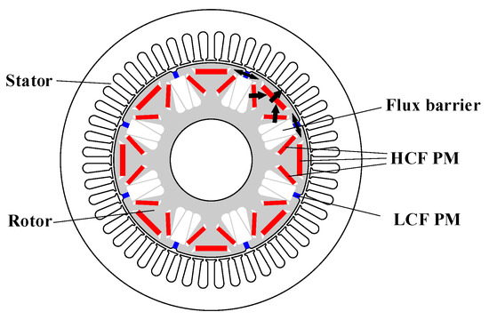
Figure 27.
Delta-type salient pole parallel-type VFM machine with extended flux barriers [77].
The configuration with W-type HCF PMs together with I-type LCF PMs is presented in the VFM machine to obtain the parallel coupling [78], as shown in Figure 28. The LCF PMs are placed at the d-axis position, and both sides are arranged with flux barriers. The risk of UD during loading operation is diminished because LCF PMs are kept away from the q-axis position. Meanwhile, the W-type HCF PMs are allocated close to the q-axis position, and accordingly their supporting effect on the LCF PMs is reduced, leading to reduced difficulty in de-magnetization.

Figure 28.
W-type LCF PM with I-type HCF PM in VFM machine [78].
4.2.3. Series
The parallel coupling between the two kinds of PMs is beneficial to the field manipulation, but the assisting effect of the HCF PMs to the LCF PMs is limited, which is unfavorable to resisting UD. In [79], an outer-rotor VFM machine with fractional-slot concentrated-windings is proposed, where the LCF and HCF PMs are alternately arranged in adjacent poles, as shown in Figure 29. As a result, the series coupling between the two kinds of PMs obtained every flux loop consists of both a HCF PM and LCF PM. As a result, the HCF PMs potentially help the LCF PMs to withstand the UD. It is also found that the MS manipulation in the fractional-slot VFM machines is related to the rotor position, and at least two magnetizing current pulses at different rotor positions are required to complete the de-/re-magnetization.
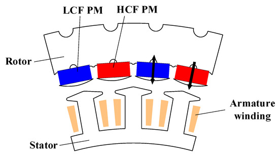
Figure 29.
VFM machine with series hybrid PMs and concentrated-windings [79].
Similarly, a series-coupling VFM machine is presented in Figure 30, in which the classic 48-slot/8-pole structure and the distributed armature windings are employed, and the V-type HCF PMs and LCF PMs are alternatively located on rotor poles [80]. Compared with the Prius 2010 IPM traction machine, this VFM machine exhibits enhanced torque output in the low-speed region and improved efficiency in the high-speed region, which are favored for the of electric vehicle applications. Due to the series coupling between the two kinds of PMs and thus the supporting effect of the HCF PM flux, the working points of LCF PMs are stable even with negative d-axis current. As a result, the UD caused by the armature reaction is mitigated, and the torque density can be boosted. Nevertheless, the unipolar z-axis leakage flux may occur if the two types of PMs are not balanced, which is revealed in [81].
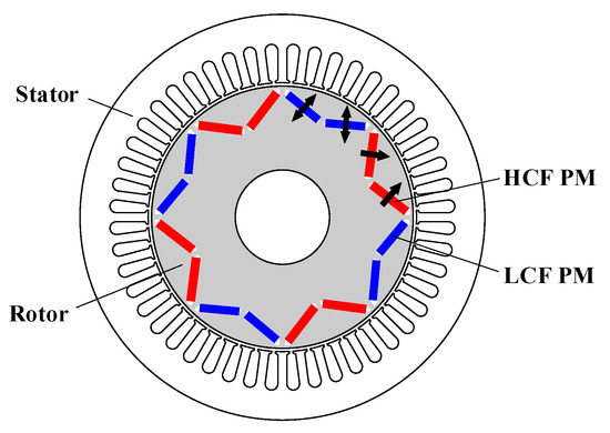
Figure 30.
48-slot/8-pole series hybrid PM VFM machine with distributed armature windings [80].
A hybrid PM VFM machine with a quasi-series PM configuration and a passive flux barrier for regulating the magnetic flux during the de-magnetizing process [82] is presented in Figure 31. The LCF PMs are located at the d-axis position, while the tangential HCF PMs are at the q-axis position. Moreover, the dimensions of the passive flux barriers close to the HCF PMs can be changed to adjust the required de/re-magnetizing current amplitudes for intentional MS regulation. Compared to the conventional series-type machines, the AlNiCo PMs are easier to de-magnetize but more difficult to re-magnetize, and the peak torque of the machine is lower.
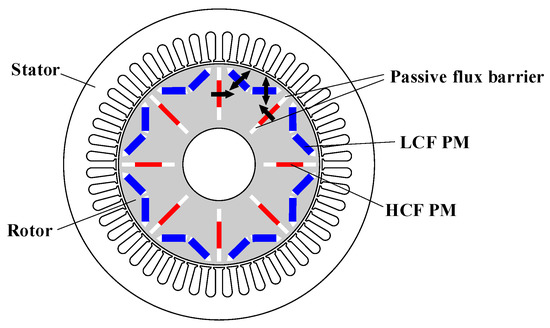
Figure 31.
Quasi-series hybrid PM VFM machine [82].
Different PM arrangements in the hybrid PM VFM machines are compared [83], and it is found that the interior-PM rotor with normal saliency is helpful in improving the torque density due to the high reluctance torque component. The V-shape PM configuration requires the lowest de/re-magnetizing currents compared to other topologies. A topology with V-type PMs is presented [84], where the half of the PM is assigned to the NdFeB PM but the other half is the newly emerged material, (Ce, Nd)-Fe-B, as illustrated in Figure 32. The two kinds of PMs are directly connected to realize the series connection. In addition to the efficiency improvement in the high-speed region due to the variable flux concept, the machine also produces comparable torque to the benchmark NdFeB machine. In [85], a dual-layer VFM machine with a double V-type PM arrangement is proposed. The two PM layers are assigned to HCF and LCF PMs. Compared to the single-layer hybrid PM VFM machines, the proposed machine exhibits a wider MS adjustment range and much lower de-magnetizing current. In [86], a double-layer VFM machine featuring I-type LCF PMs and V-type HCF PMs is presented, as shown in Figure 33. The flux barriers and adjacent iron bridges reduce the required de-magnetization current amplitude. The simulation results reveal that the proposed PM configuration benefits from the high torque, low torque ripple, low de-magnetizing current, and the good capability of withstanding UD.
Figure 32.
V-type hybrid PM VFM machine with (Ce, Nd)-Fe-B material as LCF PM [84].

Figure 33.
Double-layer hybrid PM VFM machine [86].
4.2.4. Series-Parallel
A comprehensive comparison between the series coupling and parallel coupling in VFM machines has been conducted [87,88]. It is found that parallel coupling requires lower current to achieve intentional de-magnetization, while the re-magnetizing current is lower in series coupling due to the help of the HCF PMs. In general, the flux variation range is wider in the parallel coupling machine. Moreover, although both types can improve the torque density, series coupling is more advantageous in improving the power capability due to the improved capability to resist UD. In order to integrate the merits of the two connection types, the hybrid series-parallel coupling idea is proposed.
After combining the merits of excellent UD withstanding capability in the series-coupling VFM machines and the wide MS variation range in the parallel coupling VFM machines, a pair of series-parallel coupling VFM machines were presented and compared [89]. The topology decompositions of the two types (referred to as RM-type and CM-type) are illustrated in Figure 34a. The double-layer PMs form the series and parallel magnetic circuit branches. It is found that the RM-type can produce higher torque and better UD withstanding capability, while the CM-type machine presents a slightly wider MS adjusting range. Furthermore, in contrast to the relatively complicated structure in [89], another series-parallel coupling VFM machine is proposed [90], where the HCF PMs and LCF PMs are arranged at the two layers in the interior-PM rotor. A portion of the LCF PM flux flows through the HCF PMs as the series coupling while the other portion bypasses through the iron bridges adjacent to the HCF PMs as the parallel coupling. As the two couplings both exist, the series-parallel coupling is obtained. The proposed machine can achieve compatibility between a wide MS variation range and a low required de/re-magnetizing current (around 1.5 times the rated current). Another feasible rotor design with series-parallel magnetic circuits is proposed in [91], where the NdFeB material as HCF PMs and the AlNiCo material as LCF PMs have a flexible integration for each PM block, and the series-parallel coupling occurs in the PM blocks. However, it can be observed that the proposed series-parallel hybrid PM VFM machines all have sophisticated structures, in which the mechanical robustness is sacrificed. Meanwhile, the complicated flux barriers in the rotor degrade the torque output.
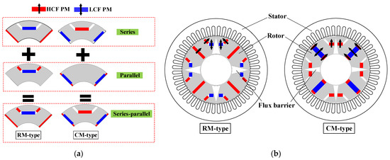
Figure 34.
Hybrid PM VFM machine with series-parallel coupling [89]. (a) Topology decomposition diagrams. (b) Topologies of RM-type and CM-type.
4.3. Stator-PM VFM Machines
The previous rotor-PM based VFM machines all feature rotor-located PMs, and their MS regulation is realized by the armature current pulse. In contrast, the stator-PM VFM machines have PMs in the stator, and specific FCs in the stator are employed to provide de-/re-magnetizing current. As the FCs and armature windings are separately employed, the inverter capacity can be effectively reduced compared to rotor-PM VFM machines. Moreover, the individual operations for the torque output and the MS manipulation facilitate high-precision control. The robust rotor core is free from either coils or PMs, which is beneficial to the harsh environment operation, thermal management, and high-speed traction applications. However, the drawbacks including the complicated structure and space conflict in the stator as well as the cost due to the extra coils and inverter cannot be neglected.
4.3.1. Single-PM
A multi-phase doubly salient PM machine integrating the VFM concept is proposed [92,93,94,95], featuring outer-rotor and double stator construction, as shown in Figure 35a. The AlNiCo PMs and FCs are allocated in the inner-layer stator, while the salient poles wound with armature windings are placed in the outer-layer stator. The salient rotor only consists of laminations. A similar inner rotor structure is shown in Figure 35b [96]. The machine benefits from improved reliability due to the high phase numbers and the robust rotor. More importantly, the LCF PMs and armature windings are physically separated, making the PMs immune from UD issue caused by the armature reaction field. The fault-tolerance capability is enhanced as a result of the adjustable PM flux.
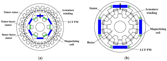
Figure 35.
Multi-phase doubly salient VFM machine. (a) Topology decomposition diagrams [92]. (b) Inner rotor topology [96].
Based on the switched-flux PM machine topology, the VFM structure can also be obtained [97]. The LCF PMs are embedded between the U-shape stator modules, while the FCs are allocated on the external side of the stator. The machine features concentrated armature coils and FCs, a robust rotor, and the MS regulation of the LCF PMs via the field current pulse. In [98], a stator-consequent-pole VFM machine is proposed, where the LCF PMs are placed between the adjacent stator tooth-openings, and the FCs are wound around the PMs, as shown in Figure 36. The armature reaction field is parallel to the LCF PM flux. The available slot/pole combinations were investigated, and the 6/7-pole configuration is reported to exhibit symmetrical back-EMF and good torque quality. The presented machine has the advantage of the easy MS manipulation, excellent ability to withstand UD, and easy thermal management.
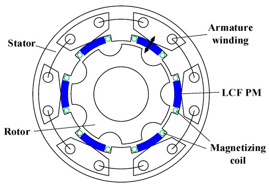
Figure 36.
Consequent-pole surface-mounted stator-PM VFM machine [98].
4.3.2. Hybrid-PM
Similar to the rotor-PM VFM machines, the hybrid PM solution is helpful in the stator-PM VFM machines for enhancing the toque density and flux regulation. Originating from the single-PM VFM machine in Figure 35a, a hybrid PM VFM machine is proposed [99]. The AlNiCo material as LCF PMs and the NdFeB material as HCF PMs are allocated side by side, and hence the parallel magnetic connection is obtained, as illustrated in Figure 37. Further, the discussion between the different PM combinations including the shape, dimension, and relative position is presented [100]. The dual-PM arrangements, i.e., top aligned without iron bridges, center aligned without iron bridges, and center aligned with iron bridges, are compared in detail, as shown in Figure 37b. It has been found that the appropriate narrow iron bridges between the NdFeB and AlNiCo PMs benefit the machine performance. Moreover, the design of the iron bridges between the two kinds of PMs is discussed, which is a key factor compromising the torque capability and flux regulation. The width of the iron bridge affects the working point elevating effect from NdFeB PMs in the flux-weakening MS and the load capacity in the flux-enhancing MS, which should be carefully designed, and a moderate value is preferred.
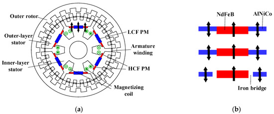
Figure 37.
Hybrid PM VFM machine based doubly salient topology. (a) Machine topology [99]. (b) Design of PM locations and iron bridge [100].
By integrating the magnetic-gearing effect and the VFM concept, a magnetic-geared VFM machine is proposed [101], as in Figure 38. The 16 pairs of NdFeB PMs are adhered to the outer rotor, while the AlNiCo PMs are embedded in the inner stator. The armature coils and FCs are both located on the inner stator. A stationary modulation ring is sandwiched between the outer rotor and inner stator, which can modulate the high-speed armature field to the low-speed PM rotor. The machine is capable of producing high torque output and extended operation range. It can be noted that this machine possesses PMs on both the stator and rotor.

Figure 38.
Hybrid PM VFM machine based on magnetic-gearing topology [101].
In [102], a pair of dual-PM VFM machines are presented, and they are depicted in Figure 39 (referred to as type-1 and type-2), where the outer rotor structure is employed for the in-wheel direct-drive traction applications. The two machines have the spoke-type AlNiCo PMs in the yokes of the stator. Meanwhile, the consequent-pole NdFeB PMs are surface-mounted on the rotor in type-1, while the consequent-pole NdFeB PMs are surface-mounted on the stator teeth in type-2. The series coupling between the two kinds of PMs is presented in the two machines. The simulation results suggest that the type-1 machine produces higher power/torque, superior efficiency, and lower torque ripple. In contrast, the higher torque ripple is observed in the type-2 machine, which is undesirable for electric vehicle applications since the driving comfortability and maintenance cost are inferior.
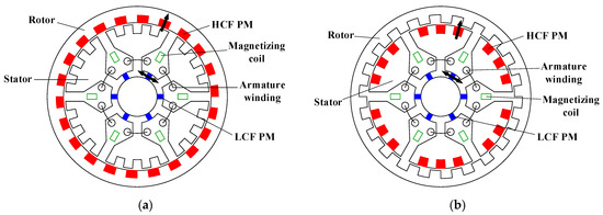
Figure 39.
Two types of hybrid PM VFM machines with LCF PM on stator [102]. (a) Type-1 (HCF PM on rotor). (b) Type-2 (HCF PM on stator).
Based on the switched-flux PM topology, the hybrid PM VFM machines with interior-PMs on the stator are proposed in [103]. As shown in Figure 40a, the parallel magnetic connection between the two types of PMs is realized by placing the LCF PMs on the stator exterior and the HCF PMs on the stator teeth. In order to address the reduced armature slot area in the U-shape modular stator, the spoke-type LCF PM arrangement was developed, and the outer rotor structure was employed [104], offering an enlarged space to alleviate the stator geometric conflict, as shown in Figure 40b. Alternatively, in [105], the E-shape modular stator is used, and the armature coils are alternately wound around the stator teeth, as shown in Figure 40c, which mitigates the space conflict in the stator. It is found that the E-core VFM machines show better UD withstanding capability than the conventional U-core machines. Moreover, the V-shape AlNiCo PMs are inserted into the switched-flux VFM machine [106], as in Figure 40d. This LCF PM arrangement can enlarge the cross-sectional area and hence contribute to the higher torque density and wider speed range. The hybridization ratio between the two types of PMs should be optimized in consideration of the neutralization of the MS regulation range and torque density.
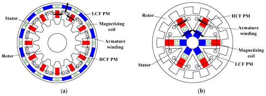
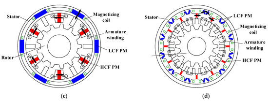
Figure 40.
Various hybrid PM VFM machines based on switched-flux topology. (a) U-core stator [103]. (b) Spoke-type PMs [104]. (c) E-core stator [105]. (d) V-type LCF PM [106].
Further, a PS stator-PM VFM machine employing three kinds of PMs, i.e., NdFeB, SmCo and AlNiCo PMs, is proposed in [107]. As shown in Figure 41, the outer stator is accommodated with the armature coils, while the inner stator has the three kinds of PMs and the FCs. The iron-piece rotor is sandwiched between the two stators. Due to the working point supporting effect from the SmCo PMs, the vulnerable AlNiCo PMs can effectively avoid the UDs. However, it can be noted that the machine suffers from a relatively complicated structure and hence weakened robustness due to its dual air-gap layout and cup-shaped rotor.

Figure 41.
Dual-stator VF-SFPM machines with different PM arrangements [107]. (a) Dual-PM. (b) Triple-PM.
4.4. Summary
The merits and demerits of diverse VFM machines are summarized in Table 2. The rotor-PM VFM machines are free from specific FCs and thus exhibit enhanced torque density and efficiency, which are attractive for traction applications. The stator-PM VFM machines originate from the stator-PM machines but require specific FCs for MS regulation. They benefit from the robust rotor and easier control on the field current in FCs, but the torque density and overall efficiency are inferior. The very first VFM machine solely employs the LCF PM to achieve flux regulation, but the relatively weak LCF PMs limit the torque density and efficiency. As a result, the hybrid PM solution integrating the LCF PMs for MS regulation and the HCF PMs for torque output is proposed. Compared with the parallel coupling between the two kinds of PMs, the series coupling is more beneficial in enhancing the capability to resist UDs caused by the PM itself or armature reaction, which is superior in torque density. Moreover, series-parallel coupling is reported to reduce the required currents for intentional de-/re-magnetization.
Table 2.
Advantages and disadvantages of various VFM machines.
5. Conclusions
In this paper, the flux-adjustable PM machines including HE, MR, and VFM machines are introduced, and a multitude of machine topologies are overviewed. HE machines adopt additional FCs to realize the air-gap field regulation. Among diverse HE topologies, the stator-excited solutions are attractive due to the brushless structures and simple configurations. The PS and dual stator techniques are helpful in alleviating the space conflict on the stator and further improving the machine performance. However, continuous field current is required for flux regulation in HE machines, which is unfavorable in efficiency-critical applications. Alternatively, MR machines relying on the mechanical actuators can achieve flux regulation with negligible power consumption. Nevertheless, the active or passive mechanical devices inevitably degrade machine compactness and robustness as well as power density. Finally, VFM machines inheriting the mature structures of rotor-PM or stator-PM synchronous machines while dissipating negligible loss for flux regulation are focused on. The rotor-PM VFM machines are free from FCs and thus benefit from simple structures as well as high power density. The hybrid PM method can further enhance the torque density of VFM machines, with which series coupling and series-parallel coupling are superior. However, the key drawbacks of VFM machines in traction systems are the high de-/re-magnetizing currents and hence the over-rating converter, which are currently extensively researched over the world.
Author Contributions
Conceptualization, H.H.; methodology, Z.Z. (Zicheng Zhou) and H.H.; Writing—original draft preparation, Z.Z. (Zicheng Zhou) and H.H.; writing—review and editing, H.H. and Z.Z. (Ziqiang Zhu); supervision, H.H. and Z.Z. (Ziqiang Zhu); project administration, H.H.; funding acquisition, H.H. and Z.Z. (Ziqiang Zhu). All authors have read and agreed to the published version of the manuscript.
Funding
This research is funded by the National Natural Science Foundation of China, funding number 52007115, and the Shanghai Sailing Program, funding number 20YF1419000.
Conflicts of Interest
The authors declare no conflict of interest.
References
- Zhu, Z.Q.; Howe, D. Electrical machines and drives for electric, hybrid, and fuel cell vehicles. Proc. IEEE 2007, 95, 746–765. [Google Scholar] [CrossRef]
- Jahns, T.M.; Kliman, G.B.; Neumann, T.W. Interior permanent-magnet synchronous motors for adjustable-speed drives. IEEE Trans. Ind. Appl. 1986, IA-22, 738–747. [Google Scholar] [CrossRef]
- Soong, W.L.; Miller, T.J.E. Field-weakening performance of brushless synchronous AC motor drives. IEE Proc.-Elec. Power Appl. 1994, 141, 331–340. [Google Scholar] [CrossRef]
- Soong, W.L.; Ertugrul, N. Field-weakening performance of interior permanent-magnet motors. IEEE Trans. Ind. Appl. 2002, 38, 1251–1258. [Google Scholar] [CrossRef] [Green Version]
- Pellegrino, G.; Vagati, A.; Guglielmi, P. Design tradeoffs between constant power speed range, uncontrolled generator operation, and rated current of IPM motor drives. IEEE Trans. Ind. Appl. 2011, 47, 1995–2003. [Google Scholar] [CrossRef] [Green Version]
- Wang, B.; Wang, J.; Sen, B.; Griffo, A.; Sun, Z.; Chong, E. A fault-tolerant machine drive based on permanent magnet-assisted synchronous reluctance machine. IEEE Trans. Ind. Appl. 2018, 54, 1349–1359. [Google Scholar] [CrossRef]
- Powers, W.R.; Wayne, F. Dynamoelectric Machine. U.S. Patent No. 2802959, 13 August 1957. [Google Scholar]
- Ferraro, L.D.; Caricchi, F.; Capponi, F.G.; Donato, G.D. Axial-flux PM starter/alternator machine with a novel mechanical device for extended weakening capabilities. In Proceedings of the IAS Annual Meeting, Seattle, WA, USA, 3–7 October 2004; pp. 1413–1419. [Google Scholar]
- Ostovic, V. Memory motors. IEEE Ind. Appl. Mag. 2003, 9, 52–61. [Google Scholar] [CrossRef]
- Zhu, Z.Q.; Cai, S. Hybrid excited permanent magnet machines for electric and hybrid electric vehicles. CES Trans. Elect. Mach. Syst. 2019, 3, 233–247. [Google Scholar] [CrossRef]
- Owen, R.; Zhu, Z.Q.; Wang, J.; Stone, D.; Urquhart, I. Review of variable-flux permanent magnet machines. In Proceedings of the International Conference on Electrical Machines and Systems (ICEMS), Beijing, China, 20–23 August 2011; pp. 1–6. [Google Scholar]
- Amara, Y.; Hlioui, S.; Belfkira, R.; Barakat, G.; Gabsi, M. Comparison of open circuit flux control capability of a series double excitation machine and a parallel double excitation machine. IEEE Trans. Veh. Tech. 2011, 60, 4149–4207. [Google Scholar] [CrossRef]
- Zhang, Z.; Ma, S.; Dai, J.; Yan, Y. Investigation of hybrid excitation synchronous machines with axial auxiliary air-gaps and non-uniform air-gaps. IEEE Trans. Ind. Appl. 2014, 50, 1729–1737. [Google Scholar] [CrossRef]
- Amara, Y.; Vido, L.; Gabsi, M.; Hoang, E.; Ahmed, A.; Lecrivain, M. Hybrid excitation synchronous machines: Energy-efficient solution for vehicles propulsion. IEEE Trans. Veh. Tech. 2009, 58, 2137–2149. [Google Scholar] [CrossRef]
- Wang, Y.; Deng, Z. Comparison of hybrid excitation topologies for flux-switching machines. IEEE Trans. Magn. 2012, 48, 2518–2527. [Google Scholar] [CrossRef]
- Hua, H.; Zhu, Z.Q. Comparative study of series and parallel hybrid excited machines. IEEE Trans. Energy Convers. 2020, 35, 1705–1714. [Google Scholar] [CrossRef]
- Henneberger, G.; Hadji-Minaglou, J.R.; Ciorba, R.C. Design and test of permanent magnet synchronous motor with auxiliary excitation winding for electric vehicle application. In Proceedings of the EPE Chapter Conference EPE Drive Design and Applications, Lausanne, Switzerland, 19–20 October 1994; pp. 645–649. [Google Scholar]
- Fodorean, D.; Djerdir, A.; Vioreal, I.; Miraoui, A. A double excited synchronous machine for direct drive application-design and prototype tests. IEEE Trans. Energy Convers. 2007, 22, 656–665. [Google Scholar] [CrossRef]
- Kamiev, K.; Nerg, J.; Pyrhonen, J.; Zaboin, V.; Hrabovcova, V.; Rafajdus, P. Hybrid excitation synchronous generators for island operation. IET Proc. Electr. Power Appl. 2012, 6, 1–11. [Google Scholar] [CrossRef]
- Luo, X.; Lip, T.A. A synchronous/permanent magnet hybrid AC machine. IEEE Trans. Energy Convers. 2000, 15, 203–210. [Google Scholar]
- Akemakou, A.D.; Phounsombat, S.K. Electrical Machine with Double Excitation, Especially a Motor Vehicle Alternator. U.S. Patent 6147429, 14 November 2000. [Google Scholar]
- Kamiev, K.; Nerg, J.; Pyrhonen, J.; Zaboin, V.; Tapia, J. Feasibility of an armature-reaction-compensated permanent magnet synchronous generator in island operation. IEEE Trans. Ind. Elect. 2014, 61, 5075–5085. [Google Scholar] [CrossRef] [Green Version]
- Boughrara, K.; Ibtiouen, R.; Lubin, T. Analytical prediction of magnetic field in parallel double excitation and spoke-type permanent magnet machines accounting for tooth-tips and shape of polar pieces. IEEE Trans. Magn. 2012, 48, 2121–2137. [Google Scholar] [CrossRef]
- Fukami, T.; Hayamizu, T.; Matsui, Y.; Shima, K.; Hanaoka, R.; Takata, S. Steady-state analysis of a permanent-magnet-assisted salient-pole synchronous generator. IEEE Trans. Energy Convers. 2010, 25, 388–393. [Google Scholar] [CrossRef]
- McCarty, F.B. Hybrid Excited Generator with Flux Control of Consequent-Pole Rotor. U.S. Patent No. 4656379, 4 April 1987. [Google Scholar]
- Spooner, E.; Khatab, S.; Nicolaou, N. Hybrid excitation of AC and DC machines. In Proceedings of the International Conference on Electrical Machines and Drives (IEMDC), London, UK, 13–15 September 1989; pp. 48–52. [Google Scholar]
- Tapia, J.; Leonardi, L.; Lipo, T.A. A design procedure for a PM machine with extended field weakening capability. In Proceedings of the IEEE Industry Applications Conference 37th IAS Annual Meeting (IAS2002), Pittsburgh, PA, USA, 13–18 October 2002; pp. 1928–1935. [Google Scholar]
- Tapia, J.; Leonardi, F.; Lipo, T.A. Consequent-pole permanent-magnet machine with extended field-weakening capability. IEEE Trans. Ind. Appl. 2003, 39, 1704–1709. [Google Scholar] [CrossRef] [Green Version]
- Zhang, Z.; Yan, Y.; Yang, S.; Bo, Z. Principle of operating and feature investigation of a new topology of hybrid excitation synchronous machine. IEEE Trans. Magn. 2008, 44, 2174–2180. [Google Scholar] [CrossRef]
- Shi, M.; Zhou, B.; Wei, J.; Zhang, Z.; Mao, Y.; Han, C. Design and practical implementation of a novel variable-speed generation system. IEEE Trans. Ind. Elect. 2011, 58, 5032–5040. [Google Scholar] [CrossRef]
- Zhang, Z.; Dai, J.; Dai, C.; Yan, Y. Design considerations of a hybrid excitation synchronous machine with magnetic shunt rotor. IEEE Trans. Magn. 2013, 49, 5566–5573. [Google Scholar] [CrossRef]
- Nedjar, B.; Hlioui, S.; Amara, Y.; Vido, L.; Gabsi, M.; Lecrivain, M. A new parallel double excitation synchronous machine. IEEE Trans. Magn. 2011, 47, 2252–2260. [Google Scholar] [CrossRef]
- Ozawa, I.; Kosaka, T.; Matsui, N. Less rare-earth magnet-high power density hybrid excitation motor designed for Hybrid Electric Vehicle drives. In Proceedings of the European Conference on Power Electronics and Applications (EPE), Barcelona, Spain, 8–10 September 2009; pp. 1–10. [Google Scholar]
- Kosaka, T.; Sridharbabu, M.; Yamamoto, M.; Matsui, N. Design studies on hybrid excitation motor for spindle drive in machine tools. IEEE Trans. Ind. Elect. 2010, 57, 3807–3813. [Google Scholar] [CrossRef]
- Melcescu, L.; Cistelecan, M.; Popescu, M.; Craiu, O. Design and development of a hybrid excited claw pole synchronous machine. In Proceedings of the International Aegean Conference on Electrical Machines and Power (ACEMP), Istanbul, Turkey, 8–11 September 2011; pp. 799–804. [Google Scholar]
- Rebhi, R.; Ibala, A.; Masmoudi, A. MEC-based sizing of a hybrid-excited claw pole alternator. IEEE Trans. Ind. Appl. 2015, 51, 211–223. [Google Scholar] [CrossRef]
- Cai, S.; Zhu, Z.Q.; Mallampalli, S.; Mipo, J.; Personnaz, S. Investigation of novel fractional slot nonoverlapping winding hybrid excited machines with different rotor topologies. IEEE Trans. Ind. Appl. 2021, 57, 468–480. [Google Scholar] [CrossRef]
- Freise, W. Heteropolar Excited Synchronous Machine. U.S. Patent No. US5051640, 24 September 1991. [Google Scholar]
- Li, Y.; Lipo, T.A. A doubly salient permanent magnet motor capable of field weakening. In Proceedings of the Annual IEEE Power Electronics Specialists Conference (PESC), Atlanta, GA, USA, 18–22 June 1995; pp. 565–571. [Google Scholar]
- Leonardi, F.; Matsuo, T.; Li, Y.; Lipo, T.A.; McCleer, P. Design considerations and test results for a doubly salient PM motor with flux control. In Proceedings of the IEEE Industry Applications Conference Thirty-First IAS Annual Meeting, San Diego, CA, USA, 6–10 October 1996; pp. 458–463. [Google Scholar]
- Zhu, X.; Cheng, M.; Zhao, W.; Liu, C.; Chau, K.T. Transient cosimulation approach to performance analysis of hybrid excited doubly salient machine consideration indirect field-circuit coupling. IEEE Trans. Magn. 2007, 43, 2558–2560. [Google Scholar] [CrossRef] [Green Version]
- Chau, K.T.; Jiang, J.; Wang, Y. A novel stator doubly fed doubly salient permanent magnet brushless machine. IEEE Trans. Magn. 2003, 39, 3001–3003. [Google Scholar] [CrossRef]
- Chau, K.T.; Li, Y.; Jiang, J.; Niu, S. Design and control of a PM brushless hybrid generator for wind power application. IEEE Trans. Magn. 2006, 42, 3497–3499. [Google Scholar] [CrossRef] [Green Version]
- Hua, W.; Zhu, Z.Q.; Cheng, M.; Pang, Y.; Howe, D. Comparison of flux-switching and doubly-salient permanent magnet brushless machines. In Proceedings of the International Conference on Electrical Machines and Systems (ICEMS), Nanjing, China, 27–29 September 2005; pp. 165–170. [Google Scholar]
- Owen, R.; Zhu, Z.Q.; Jewell, G. Hybrid-excited flux-switching permanent-magnet machines with iron flux bridges. IEEE Trans. Magn. 2010, 46, 1726–1729. [Google Scholar] [CrossRef]
- Hoang, E.; Lecrivain, M.; Gabsi, M. A new structure of a switching flux synchronous polyphased machine with hybrid excitation. In Proceedings of the European Conference on Power Electronics and Applications, Aalborg, Denmark, 2–5 September 2007; pp. 1–8. [Google Scholar]
- Hua, W.; Cheng, M.; Zhang, G. A novel hybrid excitation flux-switching motor for hybrid vehicles. IEEE Trans. Magn. 2009, 45, 4728–4731. [Google Scholar] [CrossRef]
- Gao, Y.; Li, D.; Qu, R.; Fan, X.; Li, J.; Ding, H. A novel hybrid excitation flux reversal machine for electric vehicle propulsion. IEEE Trans. Veh. Tech. 2018, 67, 171–182. [Google Scholar] [CrossRef]
- Wei, F.; Zhu, Z.Q.; Sun, X.; Yan, L.; Qi, J. Investigation of asymmetric consequent-pole hybrid excited flux reversal machines. IEEE Trans. Ind. Appl. 2022; in press. [Google Scholar]
- Hua, H.; Zhu, Z.Q. Novel partitioned stator hybrid excited switched flux machines. IEEE Trans. Energy Convers. 2017, 32, 495–504. [Google Scholar] [CrossRef]
- Chen, Z.; Zhou, N. Flux regulation ability of a hybrid excitation doubly salient machine. IET Elect. Power Appl. 2011, 5, 224–229. [Google Scholar] [CrossRef]
- Hua, W.; Zhang, G.; Cheng, M. Flux-regulation theories and principles of hybrid-excited flux-switching machines. IEEE Trans. Ind. Elect. 2015, 62, 5359–5369. [Google Scholar] [CrossRef]
- Zhang, G.; Hua, W.; Cheng, M.; Liao, J. Design and comparison of two six-phase hybrid-excited flux-switching machines for EV/HEV applications. IEEE Trans. Ind. Elect. 2016, 63, 481–493. [Google Scholar] [CrossRef]
- Syverson, C. Hybrid Alternator. U.S. Patent No. US005397975A, 14 March 1995. [Google Scholar]
- Naoe, N.; Fukami, T. Trial production of a hybrid excitation type synchronous machine. In Proceedings of the International Electric Machines and Drives Conference (IEMDC), Cambridge, MA, USA, 17–20 June 2001; pp. 545–547. [Google Scholar]
- Wang, Y.; Deng, Z.; Wang, X. A parallel hybrid excitation flux-switching generator DC power system based on direct torque linear control. IEEE Trans. Energy Convers. 2012, 27, 308–317. [Google Scholar] [CrossRef]
- Hua, H.; Zhu, Z.Q.; Zhan, H. Novel consequent-pole hybrid excited machine with separated excitation stator. IEEE Trans. Ind. Elect. 2016, 63, 4718–4728. [Google Scholar] [CrossRef]
- Hua, H.; Zhu, Z.Q. Novel parallel hybrid excited machines with separate stators. IEEE Trans. Energy Convers. 2016, 31, 1212–1220. [Google Scholar] [CrossRef]
- Evans, D.; Zhu, Z.Q.; Zhan, H.; Wu, Z.; Ge, X. Flux-weakening control performance of partitioned stator-switched flux pm machines. IEEE Trans. Ind. Appl. 2016, 52, 2350–2359. [Google Scholar] [CrossRef]
- Boldea, I.; Tutelea, L.N. PMSM with rotor PM mechanical flux-weakening (MFW) to zero for an 150kW, 600Vdc, 500-5000 rpm drive: Preliminary design with key validation. In Proceedings of the International Conference on Electrical Machines (ICEM), Lausanne, Switzerland, 4–7 September 2016; pp. 1995–2001. [Google Scholar]
- Sun, T.; Liu, X.P.; Zou, Y.L.; Huang, C.Z.; Liang, J.W. Design and optimization of a mechanical variable-leakage-flux interior permanent magnet machine with auxiliary rotatable magnetic poles. CES Trans. Elect. Machines Syst. 2021, 5, 21–29. [Google Scholar] [CrossRef]
- Al-ani, M.; Oner, Y. A novel mechanical flux weakening method for flux switching permanent magnet machine. Elect. Power Compo. Syst. 2021, 48, 1992–2004. [Google Scholar] [CrossRef]
- Kwon, T.S.; Sul, S.K.; Alberti, L.; Bianchi, N. Design and control of an axial-flux machine for a wide flux-weakening operation region. IEEE Trans. Ind. Appl. 2009, 45, 1258–1265. [Google Scholar] [CrossRef]
- Urquhart, I.; Tanaka, D.; Owen, R.; Zhu, Z.Q.; Wang, J.B.; Stone, D.A. Mechanically actuated variable flux IPMSM for EV and HEV applications. In Proceedings of the International World Electric Vehicle Symposium and Exhibition, Barcelona, Spain, 17–20 November 2013; pp. 1–12. [Google Scholar]
- Tessarolo, A.; Mezzarobba, M.; Menis, R. Modeling, analysis, and testing of a novel spoke-type interior permanent magnet motor with improved flux weakening capability. IEEE Trans. Magn. 2015, 51, 1–10. [Google Scholar] [CrossRef]
- Zhu, Z.Q.; Al-ani, M.M.J.; Liu, X.; Lee, B. A mechanical flux weakening method for switched flux permanent magnet machines. IEEE Trans. Energy Convers. 2015, 30, 806–815. [Google Scholar] [CrossRef]
- Liu, H.C.; Lin, H.Y.; Fang, S.H.; Huang, X.L. Investigation of permanent magnet shape on field-control parameters of variable flux memory motor with FEM. In Proceedings of the World Automation Congress, Waikoloa, Hl, USA, 28 September–2 October 2008; pp. 1–4. [Google Scholar]
- Liu, H.C.; Lin, H.Y.; Fang, S.H.; Zhu, Z.Q. Permanent magnet de-magnetization physics of a variable flux memory motor. IEEE Trans. Magn. 2009, 45, 4736–4739. [Google Scholar]
- Liu, H.C.; Lin, H.Y.; Zhu, Z.Q.; Huang, M.M.; Jin, P. Permanent-magnet remagnetizing physics of a variable flux memory motor. IEEE Trans. Magn. 2010, 46, 1679–1682. [Google Scholar] [CrossRef]
- Kato, T.; Limsuwan, N.; Yu, C.; Akatsu, K.; Lorenz, R.D. Rare earth reduction using a novel variable magnetomotive force, flux intensified IPM machine. In Proceedings of the IEEE Energy Conversion Congress and Exposition (ECCE), Raleigh, NC, USA, 15–20 September 2012; pp. 4346–4353. [Google Scholar]
- Ibrahim, M.; Masisi, L.; Pillay, P. Design of variable-flux permanent-magnet machines using Alnico magnets. IEEE Trans. Ind. Appl. 2015, 51, 4482–4491. [Google Scholar] [CrossRef]
- Sun, A.; Li, J.; Qu, R.H.; Chen, J.H.; Lu, H.X. Rotor design considerations for a variable-flux flux-intensifying interior permanent magnet machine with improved torque quality and reduced magnetization current. In Proceedings of the IEEE Energy Conversion Congress and Exposition (ECCE), Montreal, QC, Canada, 20–24 September 2015; pp. 784–790. [Google Scholar]
- Chen, Y.G.; Pan, W.; Wang, Y.; Tang, R.Y.; Wang, J. Interior composite-rotor controllable-flux PMSM-memory motor. In Proceedings of the International Conference on Electrical Machines and Systems (ICEMS), Nanjing, China, 27–29 September 2005; pp. 446–449. [Google Scholar]
- Sakai, K.; Yuki, K.; Hashiba, Y.; Takahashi, N.; Yasui, K. Principle of the variable-magnetic-force memory motor. In Proceedings of the International Conference on Electrical Machines and Systems (ICEMS), Tokyo, Japan, 15–18 November 2009; pp. 1–6. [Google Scholar]
- Zhou, Y.B.; Chen, Y.S.; Shen, J.X. Analysis and improvement of a hybrid permanent-magnet memory motor. IEEE Trans. Energy Convers. 2016, 31, 915–923. [Google Scholar] [CrossRef]
- Wang, M.; Tong, C.; Qiao, G.; Liu, F.; Guo, J.; Zheng, P. Research on electromagnetic performance of a novel hybrid-PM variable-flux machine. In Proceedings of the International Conference on Electrical Machines and Systems (ICEMS), Harbin, China, 11–14 August 2019; pp. 1–5. [Google Scholar]
- Tsunata, R.; Takemoto, M.; Ogasawara, S.; Orikawa, K. A proposal of a delta-type salient pole variable flux memory motor having large flux barrier for traction applications. In Proceedings of the IEEE Energy Conversion Congress and Exposition (ECCE), Baltimore, MD, USA, 29 September–3 October 2019; pp. 6054–6061. [Google Scholar]
- Hu, Y.S.; Chen, B.; Xiao, Y.; Li, X.; Zhang, Z.D.; Shi, J.F.; Li, L.Y. Research and design on reducing the difficulty of magnetization of a hybrid permanent magnet memory motor. IEEE Trans. Energy Convers. 2020, 35, 1421–1431. [Google Scholar]
- Maekawa, S.; Yuki, K.; Matsushita, M.; Nitta, I.; Hasegawa, Y.; Shiga, T.; Hosoito, T.; Nagai, K.; Kubota, H. Study of the magnetization method suitable for fractional-slot concentrated-winding variable magnetomotive-force memory motor. IEEE Trans. Power Elect. 2014, 29, 4877–4887. [Google Scholar] [CrossRef]
- Hua, H.; Zhu, Z.Q.; Pride, A.; Deodhar, R.P.; Sasaki, T. A novel variable flux memory machine with series hybrid magnets. IEEE Trans. Ind. Appl. 2017, 53, 4396–4405. [Google Scholar] [CrossRef]
- Zhu, Z.Q.; Hua, H.; Pride, A.; Deodhar, R.; Sasaki, T. Analysis and reduction of unipolar leakage flux in series hybrid permanent-magnet variable flux memory machines. IEEE Trans. Magn. 2017, 53, 1–4. [Google Scholar] [CrossRef]
- Zhang, S.K.; Zheng, P.; Jahns, T.M.; Cheng, L.M.; Wang, M.Q.; Sui, Y. A novel variable-flux permanent-magnet synchronous machine with quasi-series magnet configuration and passive flux barrier. IEEE Trans. Magn. 2018, 54, 1–5. [Google Scholar]
- Ibrahim, M.; Pillay, P. Design of hybrid variable flux motors for enhanced wide-speed performance. In Proceedings of the IEEE Energy Conversion Congress and Exposition (ECCE), Baltimore, MD, USA, 29 September–3 October 2019; pp. 6046–6053. [Google Scholar]
- Zhang, S.K.; Zheng, P.; Liu, Y.; Wang, M.Q.; Qiao, G.Y.; Liu, F.L. A high-torque-density variable-flux memory machine utilizing novel (Ce, Nd)-Fe-B magnets. IEEE Trans. Magn. 2021, 57, 1–6. [Google Scholar] [CrossRef]
- Yang, H.; Zhu, Z.Q.; Lyu, S.; Wang, H. A novel dual-layer PM variable flux hybrid memory machine. In Proceedings of the IEEE Energy Conversion Congress and Exposition (ECCE), Portland, OR, USA, 23–27 September 2018; pp. 262–268. [Google Scholar]
- Yang, H.; Lin, H.; Zhu, Z.Q.; Lyu, S. A novel variable flux dual-layer hybrid magnet memory machine with bypass airspace barriers. In Proceedings of the IEEE International Electric Machines & Drives Conference (IEMDC), San Diego, CA, USA, 12–15 May 2019; pp. 2259–2264. [Google Scholar]
- Athavale, A.; Sasaki, K.; Gagas, B.S.; Kato, T.; Lorenz, R.D. Variable flux permanent magnet synchronous machine (VF-PMSM) design methodologies to meet electric vehicle traction requirements with reduced losses. IEEE Trans. Ind. Appl. 2017, 53, 4318–4326. [Google Scholar] [CrossRef]
- Hua, H.; Zhu, Z.Q.; Pride, A.; Deodhar, R.P.; Sasaki, T. Comparative study on variable flux memory machines with parallel or series hybrid magnets. IEEE Trans. Ind. Appl. 2019, 55, 1408–1419. [Google Scholar] [CrossRef]
- Yang, H.; Zheng, H.; Lin, H.Y.; Zhu, Z.Q.; Fu, W.N.; Liu, W.; Lei, J.X.; Lyu, S.K. Investigation of hybrid-magnet-circuit variable flux memory machines with different hybrid magnet configurations. IEEE Trans. Ind. Appl. 2021, 57, 340–351. [Google Scholar] [CrossRef]
- Sakai, K.; Kataoka, S. Variable-magnetization PM-motor yield widely variable flux due to small magnetizing current. In Proceedings of the International Conference on Electrical Machines (ICEM), Gothenburg, Sweden, 23–26 August 2020; pp. 741–747. [Google Scholar]
- Qiao, G.Y.; Wang, M.Q.; Liu, F.L.; Liu, Y.; Zheng, P. Analysis of novel hybrid-PM variable-flux PMSMs with series-parallel magnetic circuits. IEEE Trans. Magn. 2021, 57, 1–6. [Google Scholar] [CrossRef]
- Gong, Y.; Chau, K.T.; Jiang, J.Z.; Yu, C.; Li, W. Analysis of doubly salient memory motors using Preisach theory. IEEE Trans. Magn. 2009, 45, 4676–4679. [Google Scholar] [CrossRef] [Green Version]
- Yu, C.; Chau, K.T. Dual-mode operation of DC-excited memory motors under flux regulation. IEEE Trans. Ind. Appl. 2011, 47, 2031–2041. [Google Scholar] [CrossRef] [Green Version]
- Yu, C.; Chua, K.T. New fault-tolerant flux-mnemonic doubly-salient permanent-magnet motor drive. IET Elect. Power Appl. 2011, 5, 393–403. [Google Scholar] [CrossRef]
- Yu, C.; Chau, K.T. Design, analysis, and control of DC-excited memory motors. IEEE Trans. Energy Conver. 2011, 26, 479–489. [Google Scholar] [CrossRef]
- Yu, C.; Niu, S.; Ho, S.; Fu, W.; Li, L. Hysteresis modeling in transient analysis of electric motors with AlNiCo magnets. IEEE Trans. Magn. 2015, 51, 1–4. [Google Scholar]
- Yang, H.; Lin, H.Y.; Zhuang, E.; Fang, S.H.; Huang, Y.K. Investigation of design methodology for non-earth variable-flux switched-flux memory machines. IET Elect. Power Appl. 2016, 10, 744–756. [Google Scholar] [CrossRef]
- Yang, H.; Lin, H.; Fang, S.; Huang, Y.; Zhu, Z.Q. A novel stator-consequent-pole memory machine. In Proceedings of the IEEE Energy Conversion Congress and Exposition (ECCE), Milwaukee, WI, USA, 18–22 September 2016; pp. 1–8. [Google Scholar]
- Li, W.N.; Chau, K.T.; Gong, Y.; Jiang, J.Z.; Li, F.H. A new flux-mnemonic dual-magnet brushless machine. IEEE Trans. Magn. 2011, 47, 4223–4226. [Google Scholar] [CrossRef]
- Li, F.; Chau, K.T.; Liu, C. Design of dual-magnet memory machines. In Proceedings of the International Conference on Electrical Machines and Systems (ICEMS), Beijing, China, 20–23 August 2011; pp. 1–6. [Google Scholar]
- Liu, C.H.; Chau, K.T.; Qiu, C. Design and analysis of a new magnetic-geared memory machine. IEEE Trans. Appl. Superconduct. 2014, 24, 1–5. [Google Scholar]
- Yang, H.; Lin, H.Y.; Zhu, Z.Q.; Fang, S.H.; Huang, Y.K. Novel flux-regulatable dual-magnet vernier memory machines for electric vehicle propulsion. IEEE Trans. Appl. Superconduct. 2014, 24, 1–5. [Google Scholar]
- Liu, X.; Wu, D.; Zhu, Z.Q.; Pride, A.; Deodhar, R.P.; Sasaki, T. Efficiency improvement of switched flux PM memory machine over interior PM machine for EV/HEV applications. IEEE Trans. Magn. 2014, 50, 1–4. [Google Scholar] [CrossRef]
- Yang, H.; Lin, H.Y.; Zhu, Z.Q.; Guo, K.K.; Wang, D.; Fang, S.H.; Huang, Y.K. Flux-concentrated external-rotor switched flux memory machines for direct-drive applications. IEEE Trans. Appl. Superconduct. 2016, 26, 1–6. [Google Scholar] [CrossRef]
- Yang, H.; Zhu, Z.Q.; Lin, H.Y.; Wu, D.; Hua, H.; Fang, S.H.; Huang, Y.K. Novel high-performance switched flux hybrid magnet memory machines with reduced rare-earth magnets. IEEE Trans. Ind. Appl. 2016, 52, 3901–3915. [Google Scholar] [CrossRef]
- Yang, H.; Lin, H.Y.; Zhu, Z.Q.; Wang, D.; Fang, S.H.; Huang, Y.K. A variable-flux hybrid-PM switched-flux memory machine for EV/HEV applications. IEEE Trans. Ind. Appl. 2016, 52, 2203–2214. [Google Scholar] [CrossRef]
- Yang, H.; Zhu, Z.Q.; Lin, H.Y.; Zhang, Y.; Fang, S.H.; Huang, Y.K.; Feng, N.J. Performance improvement of partitioned stator switched flux memory machines with triple-magnet configuration. IEEE Trans. Magn. 2016, 52, 1–4. [Google Scholar] [CrossRef]
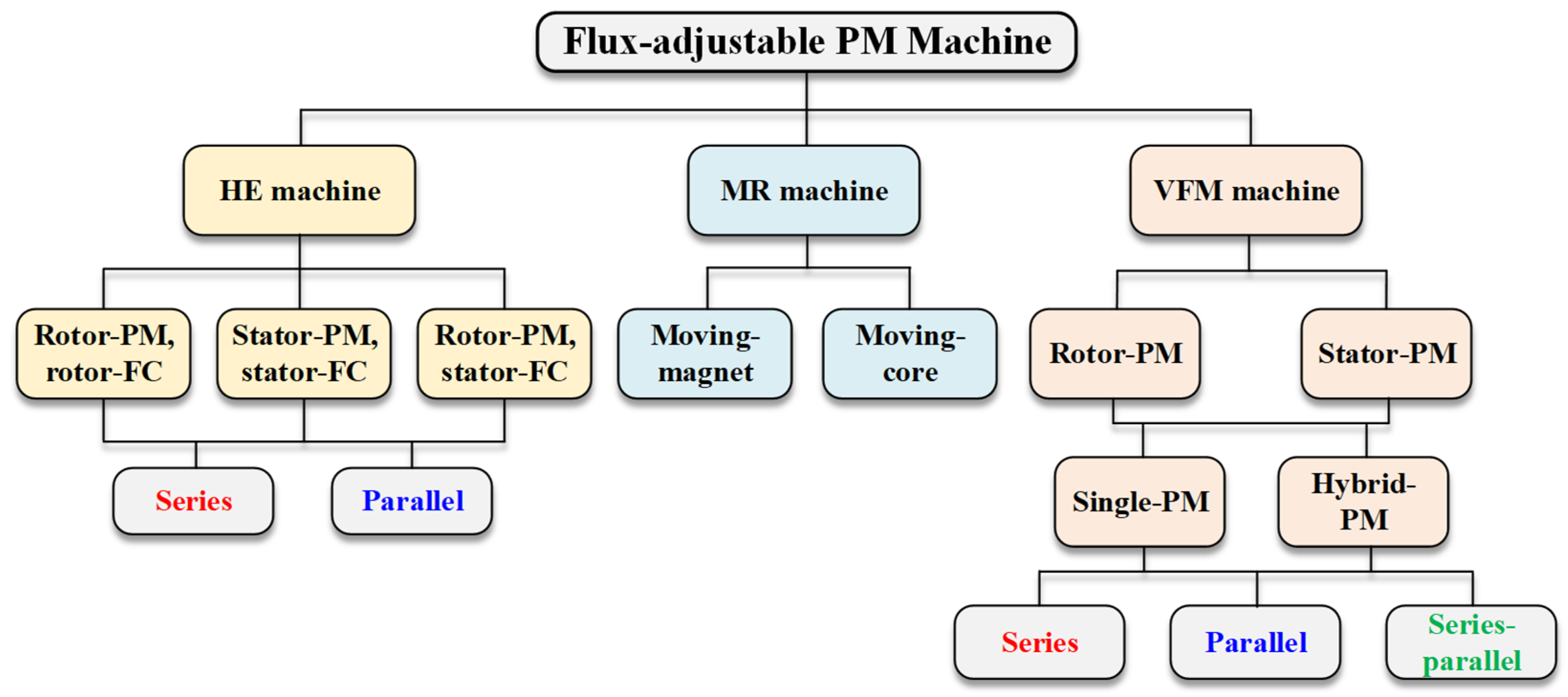
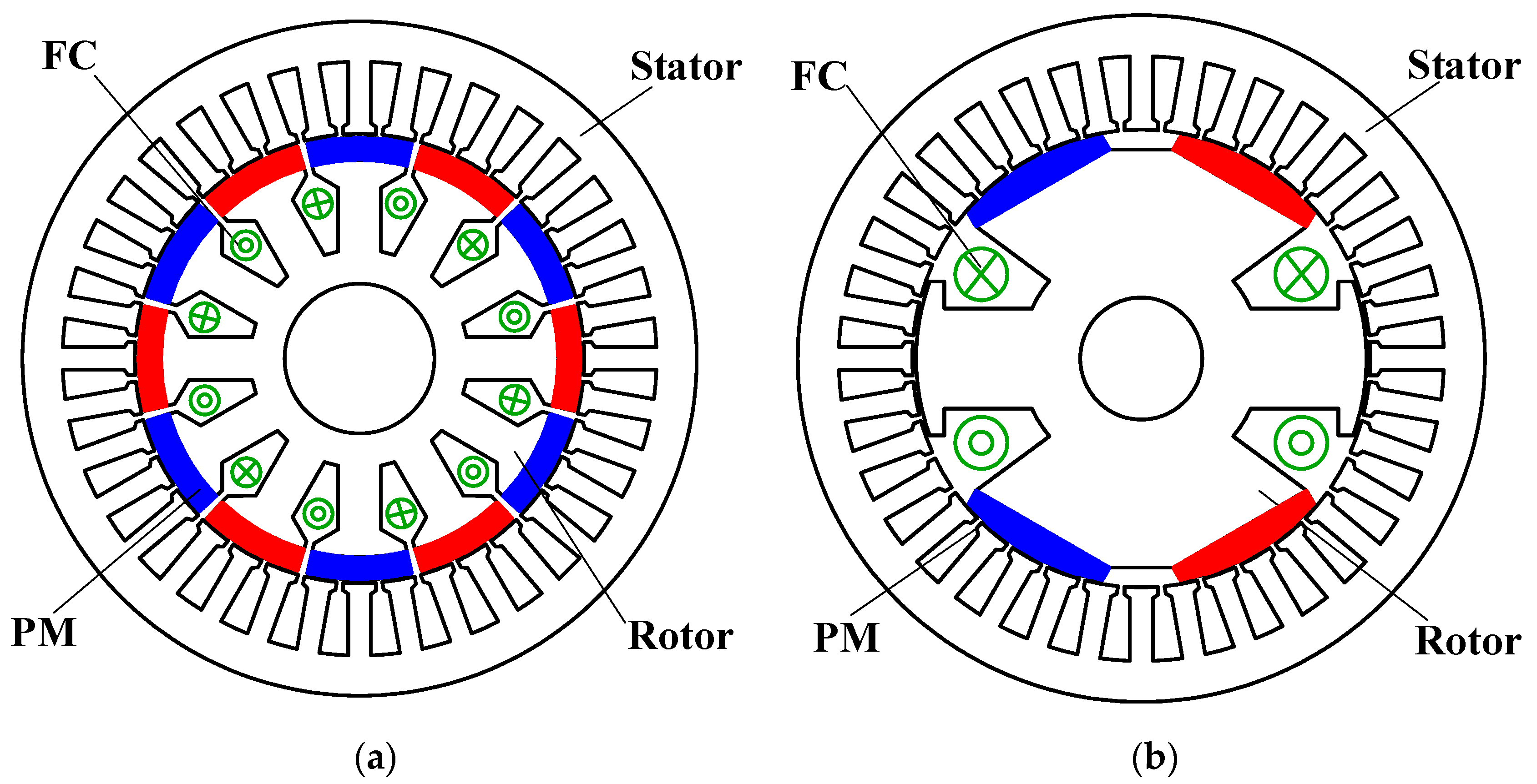
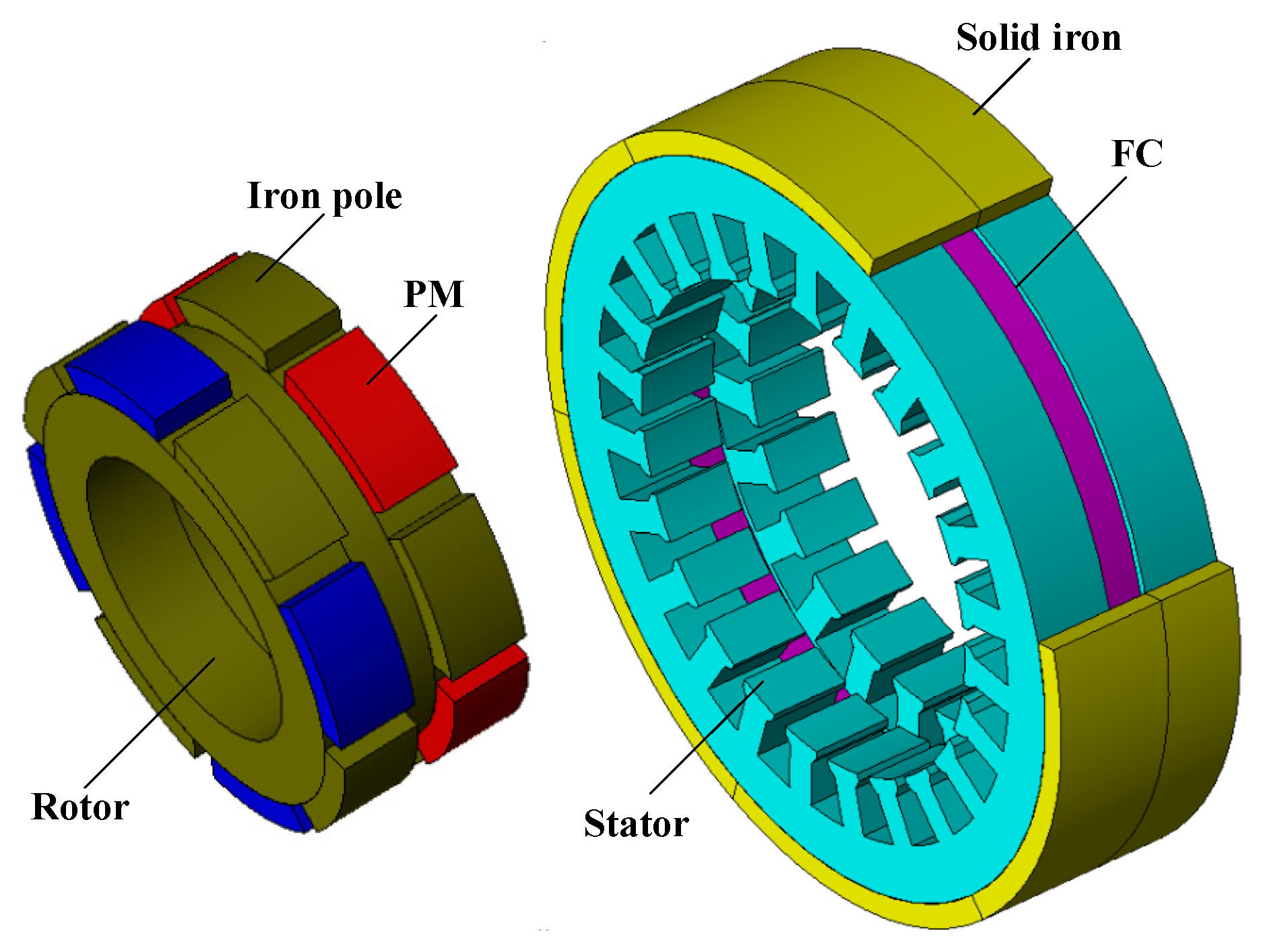
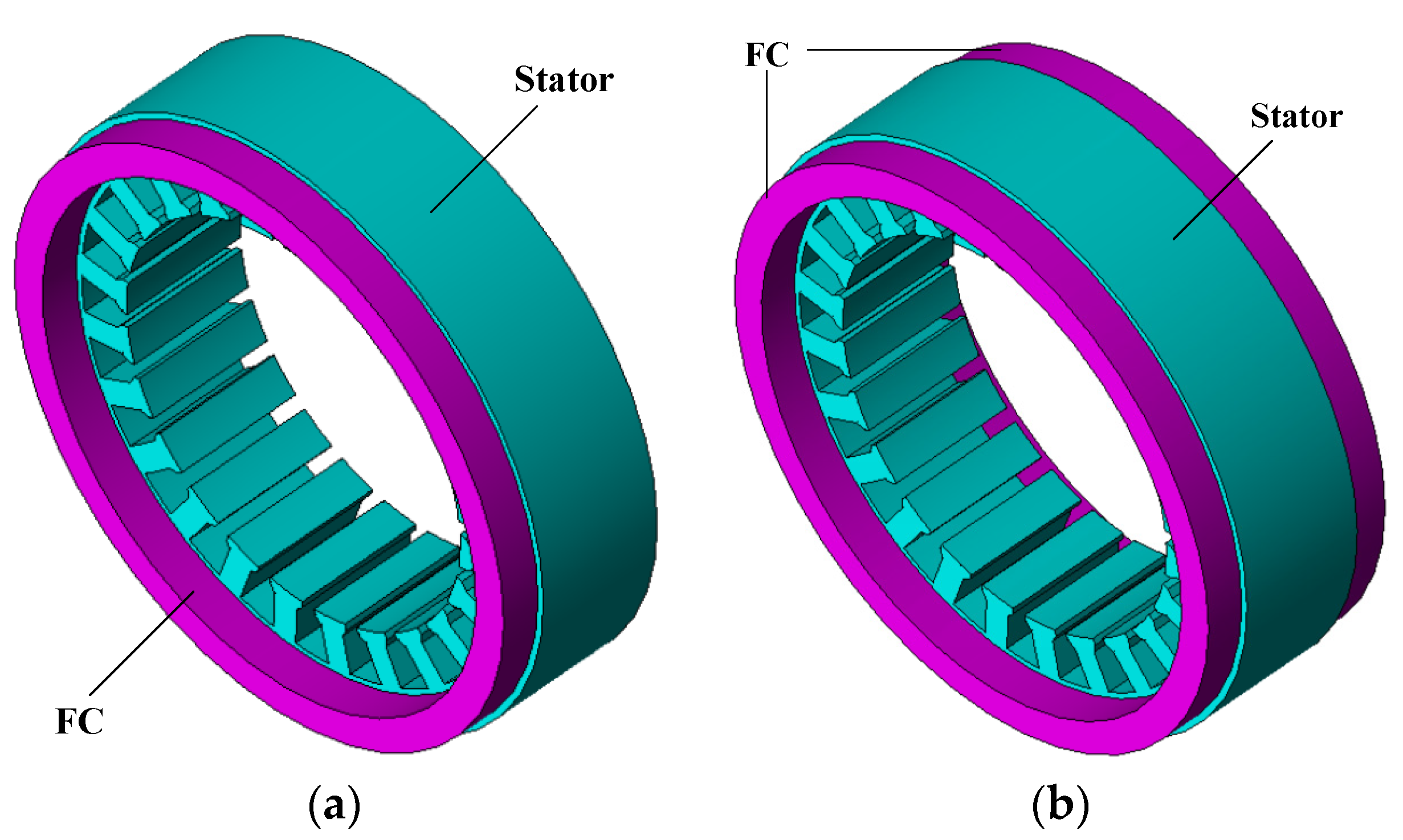
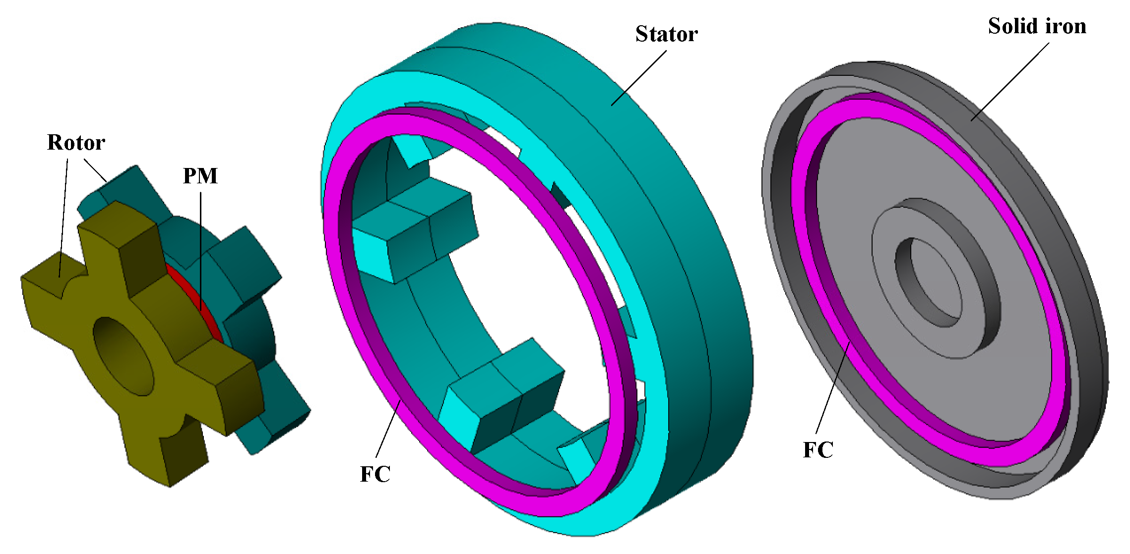

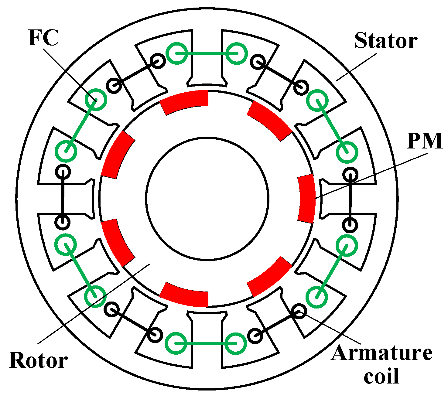
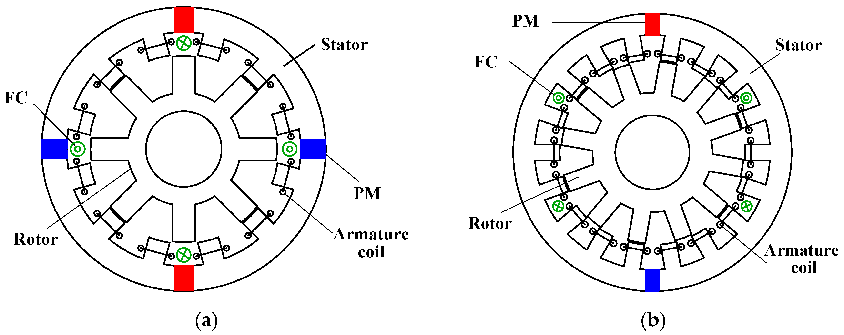
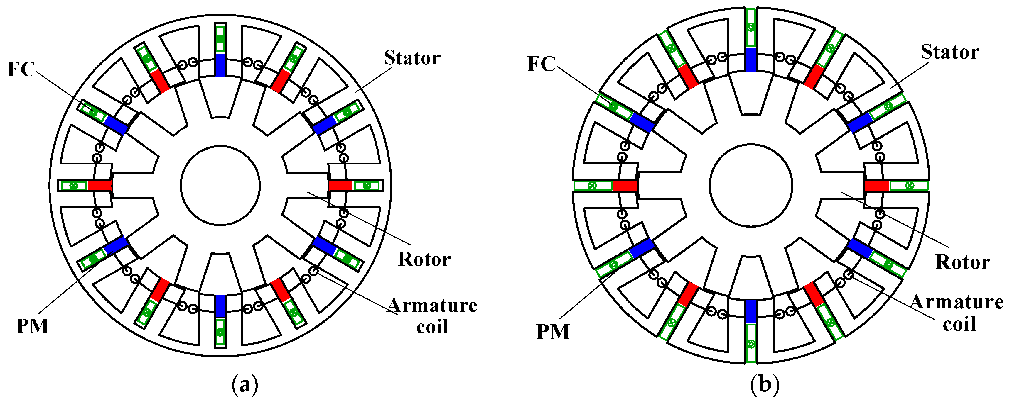
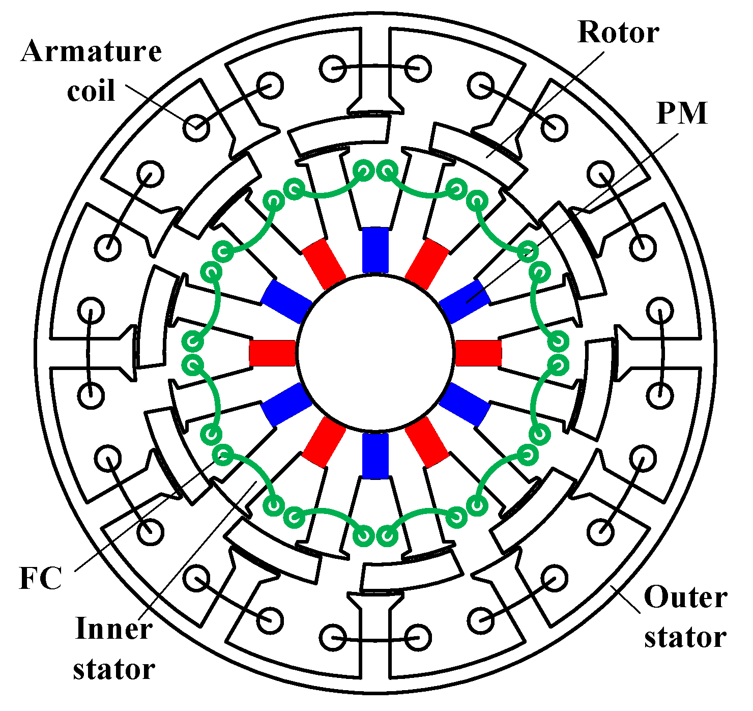

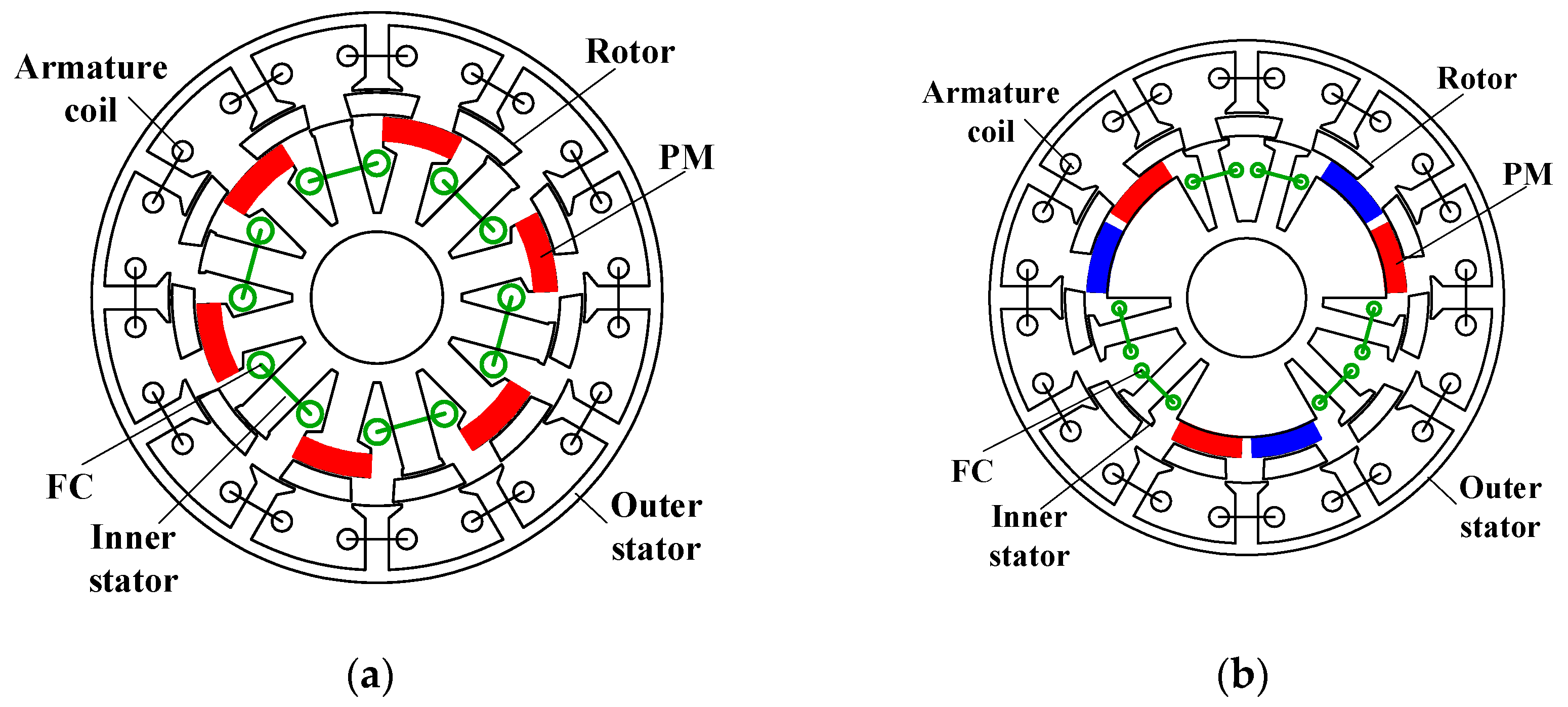
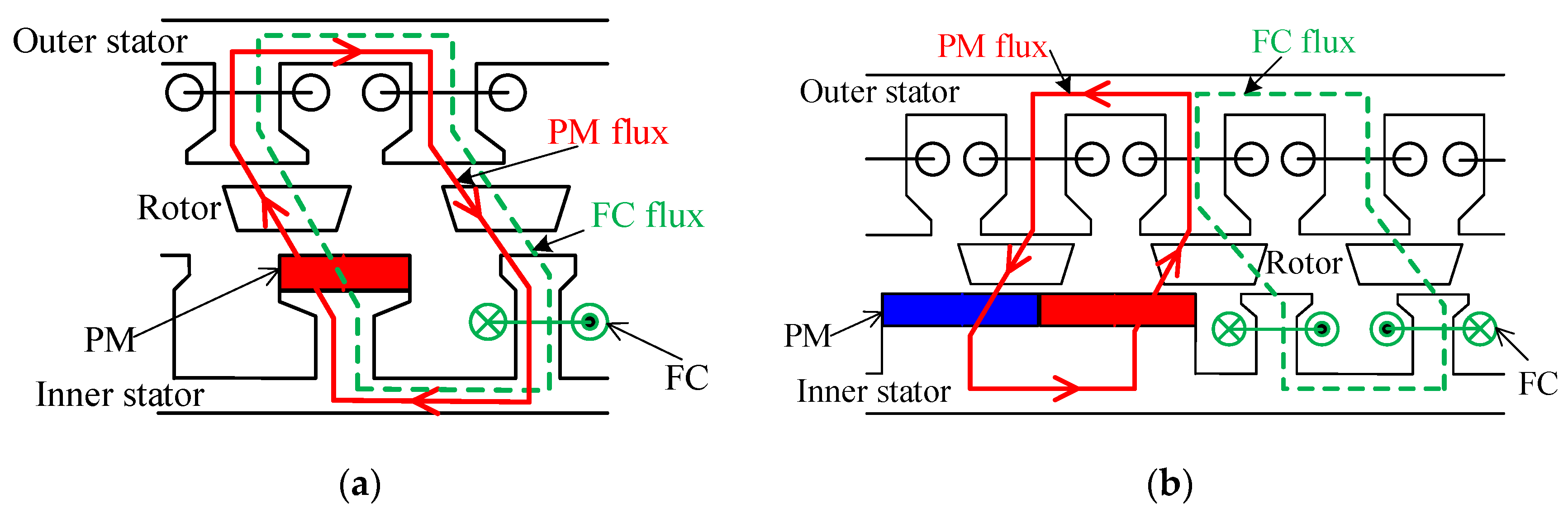
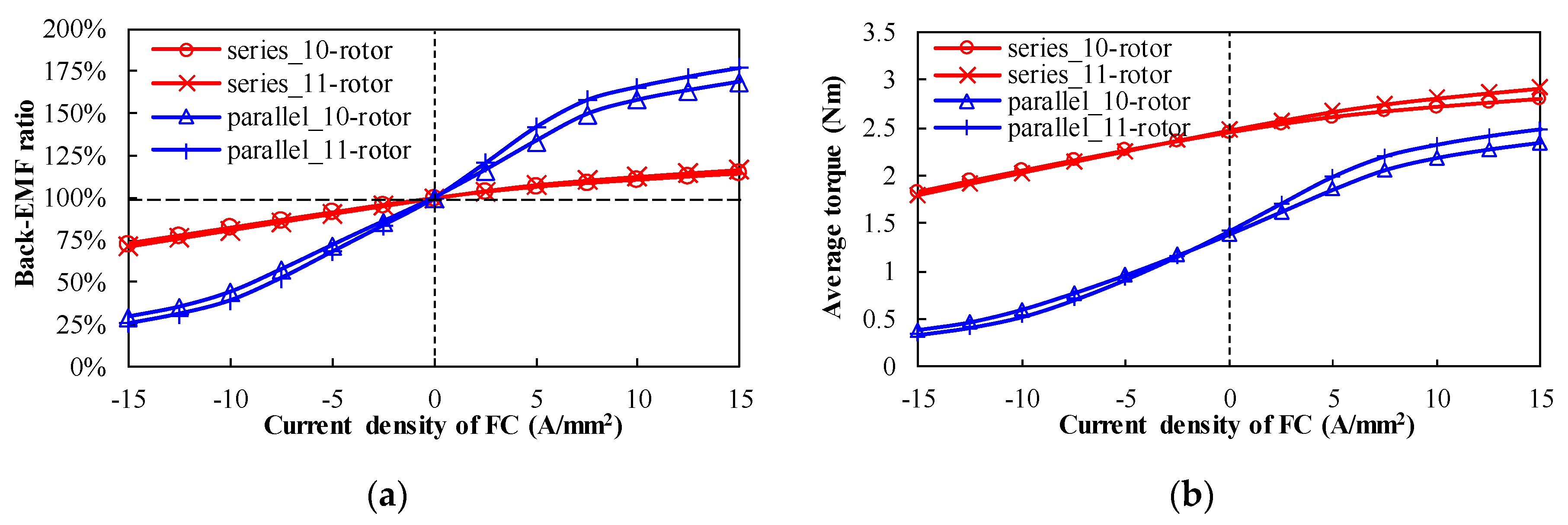
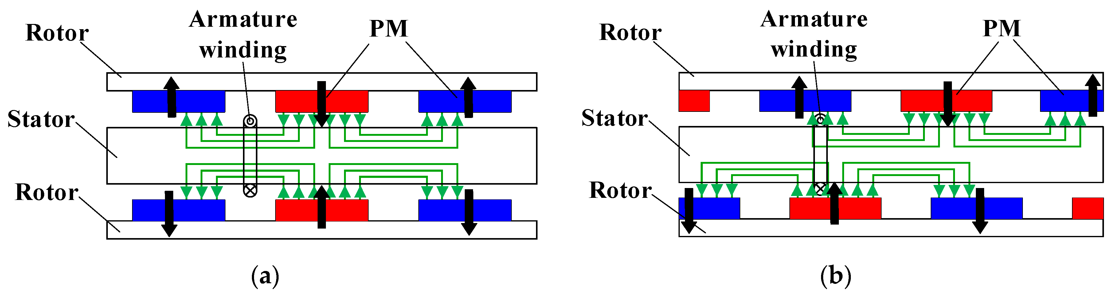
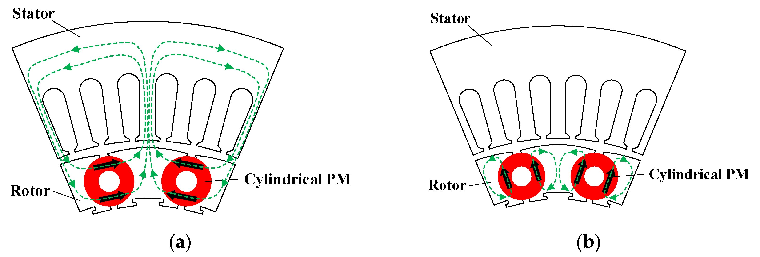

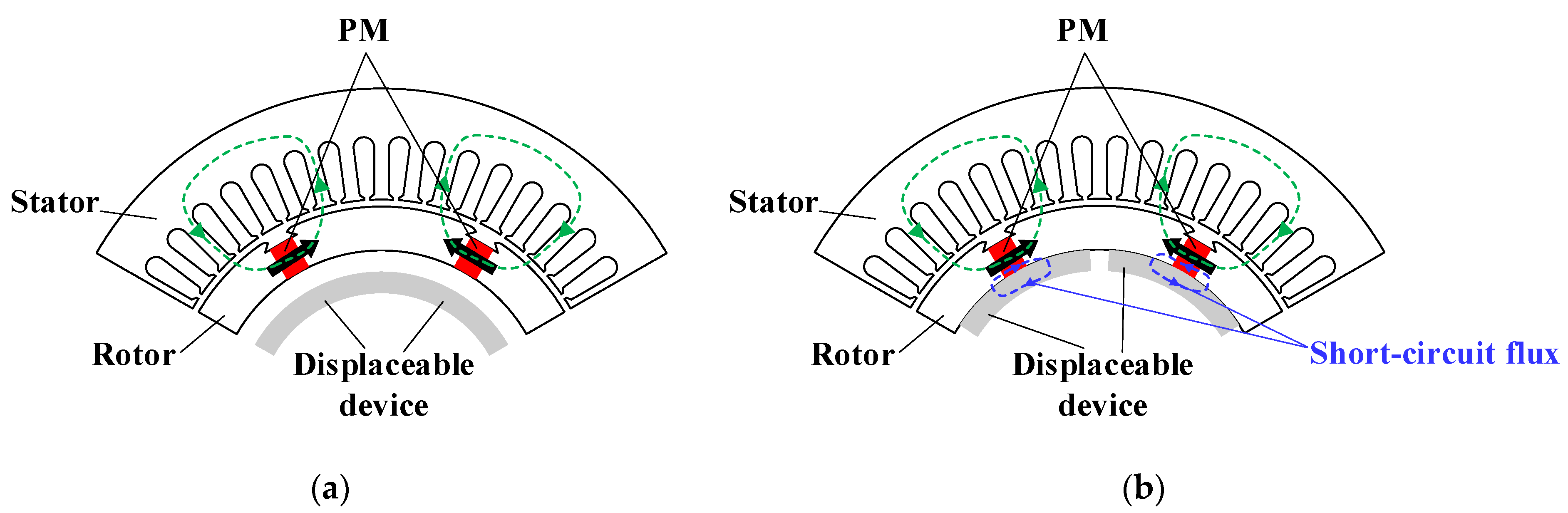

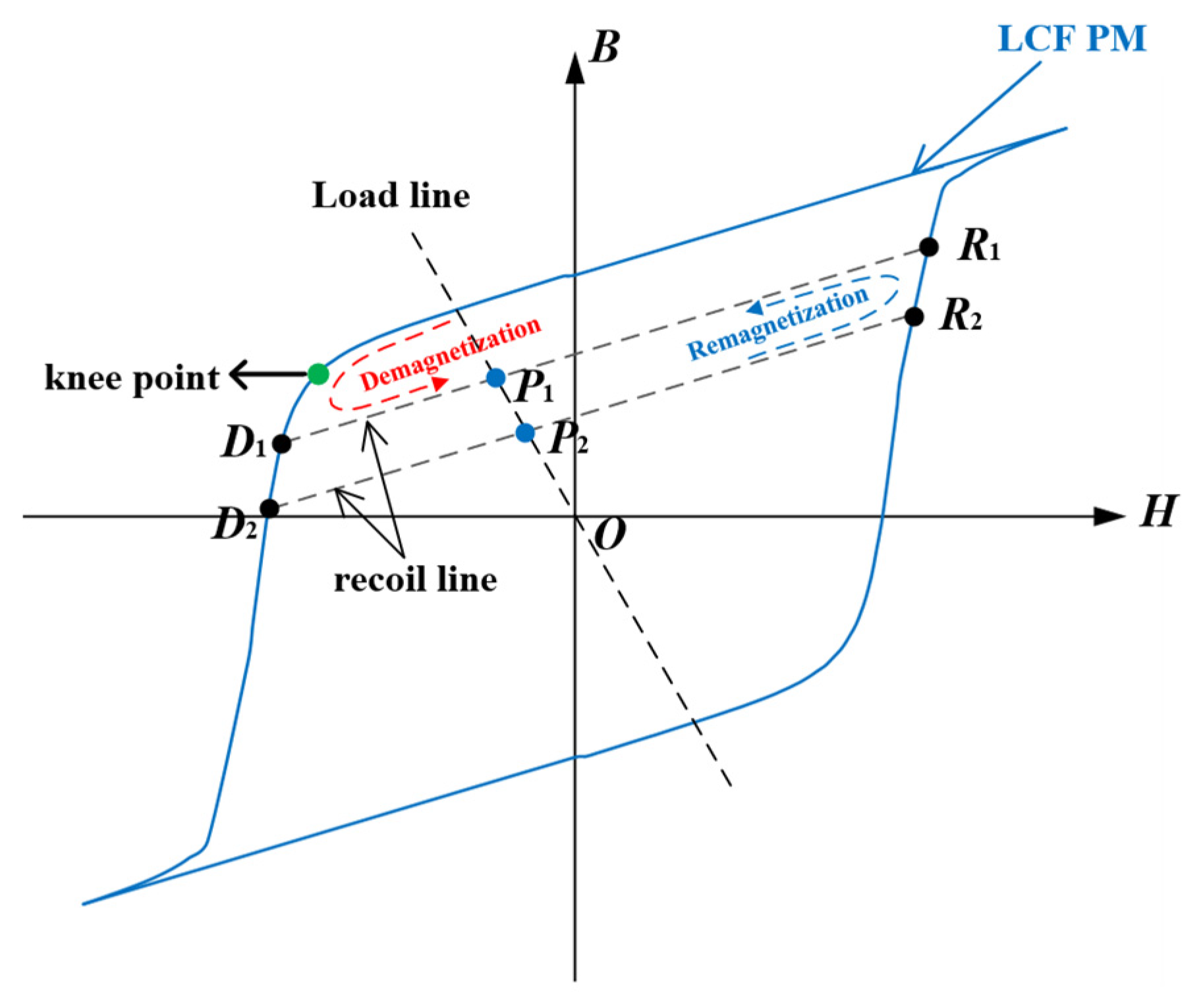
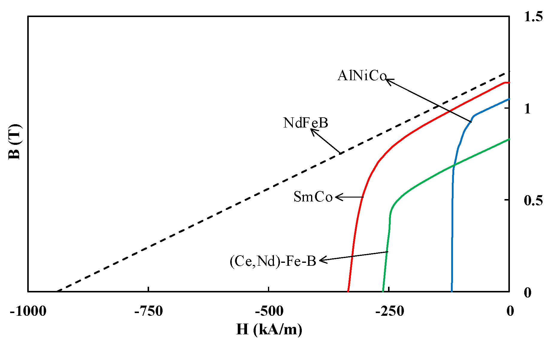

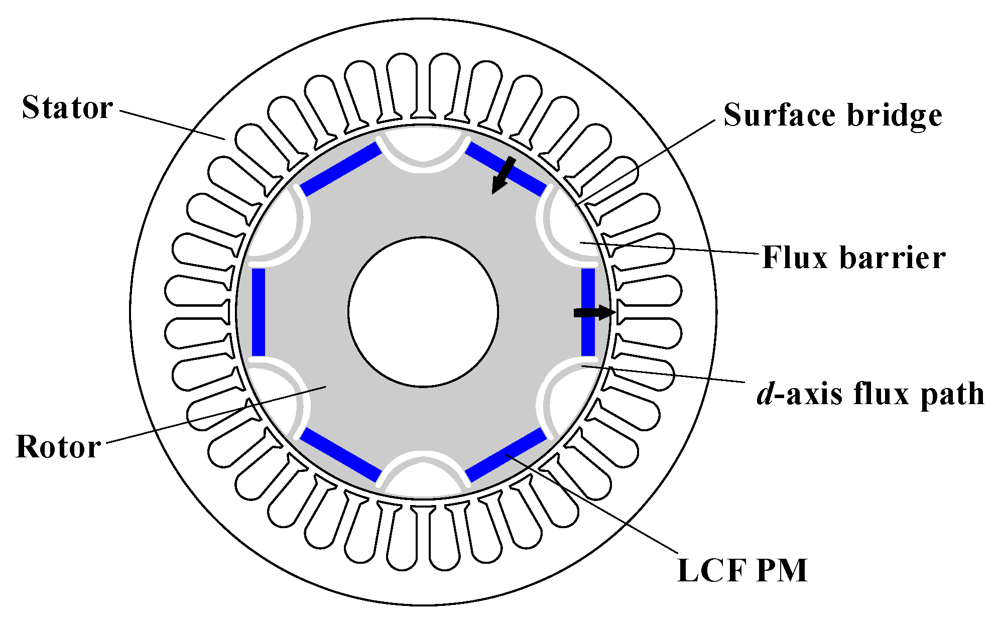
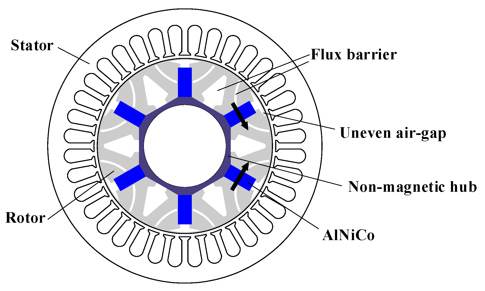
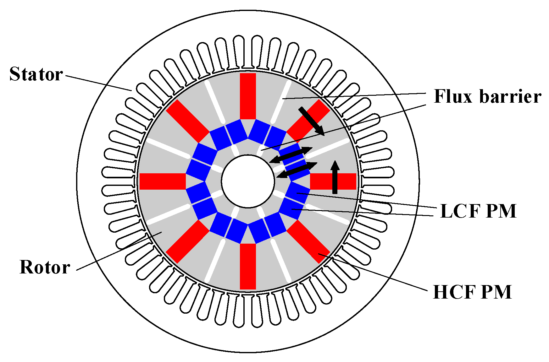
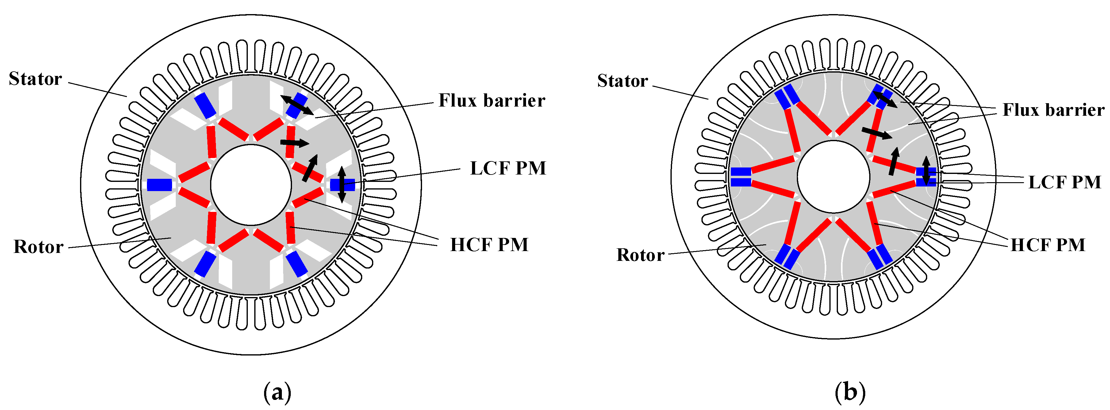
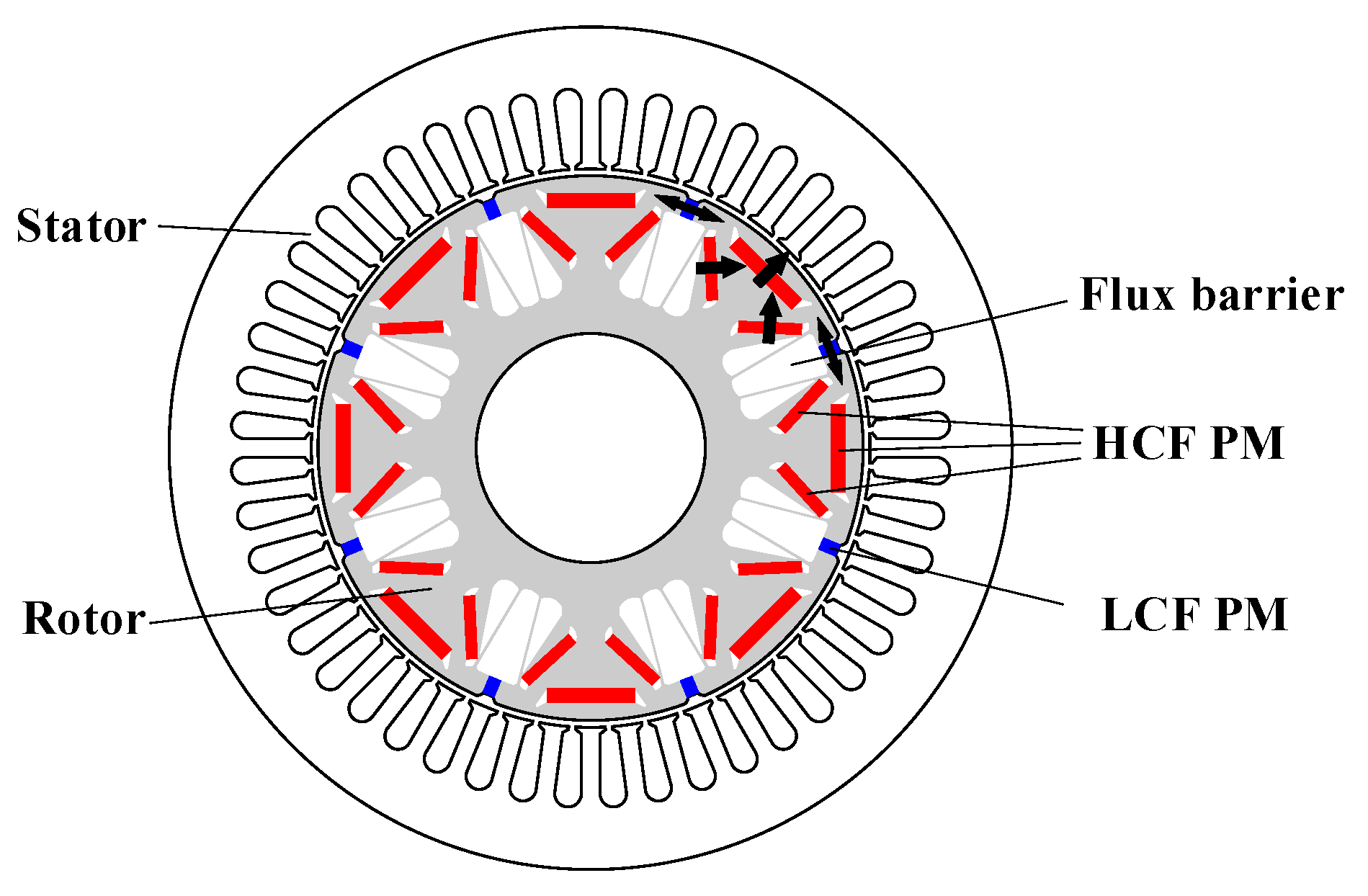
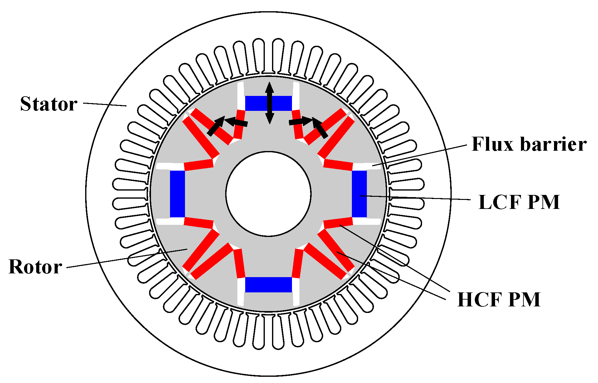
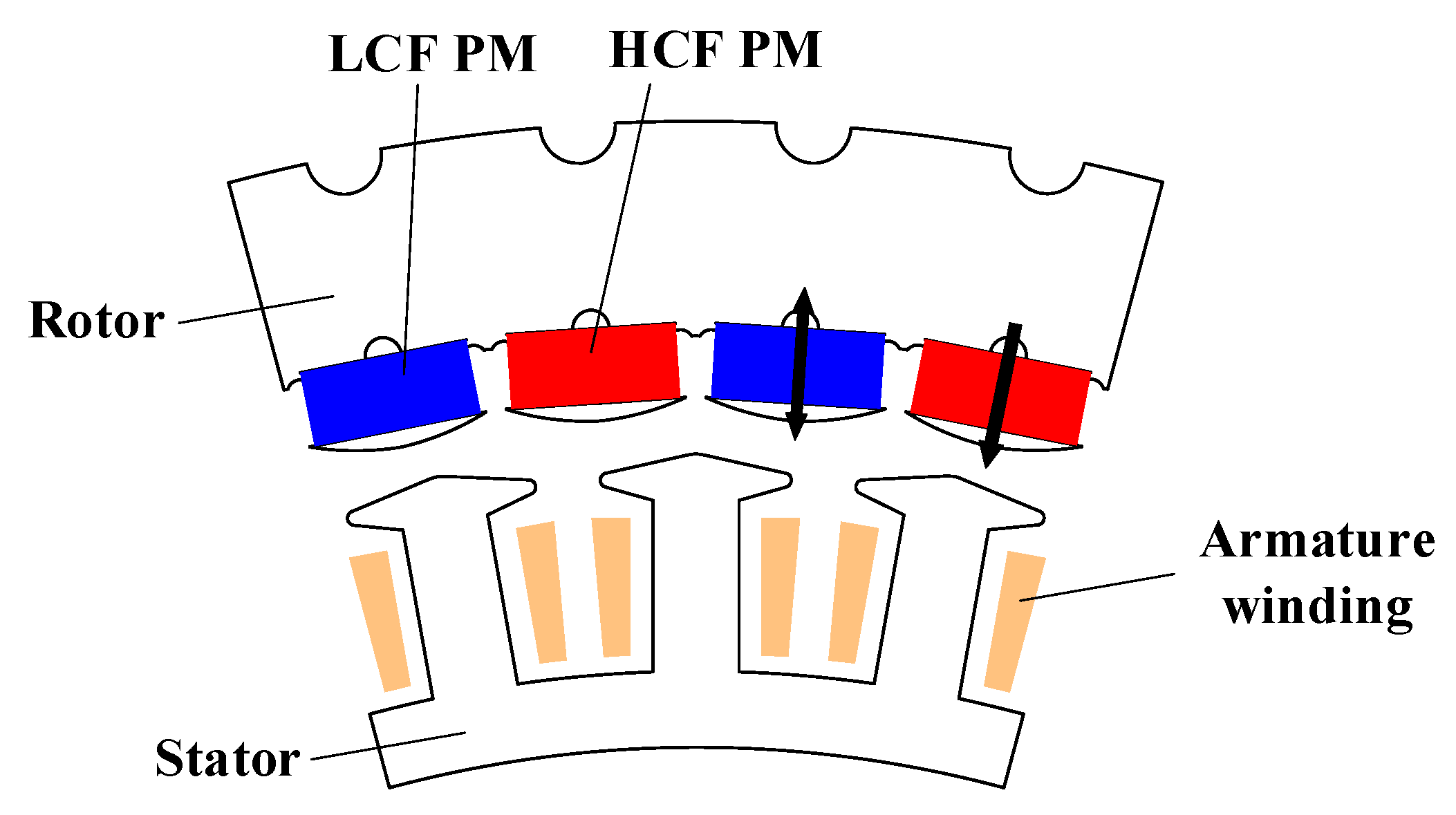
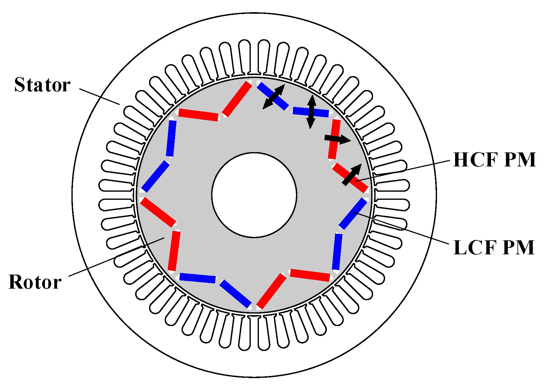
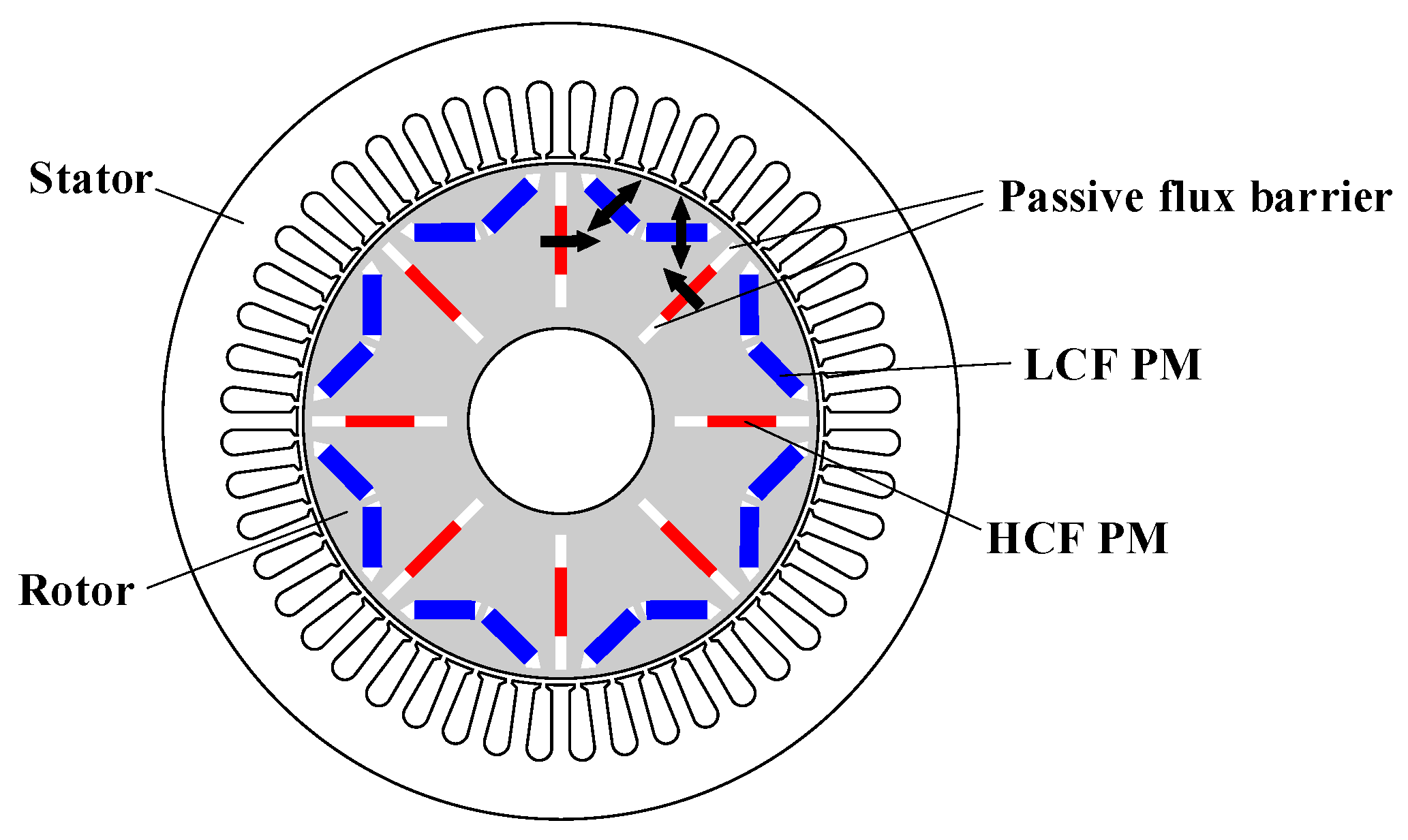
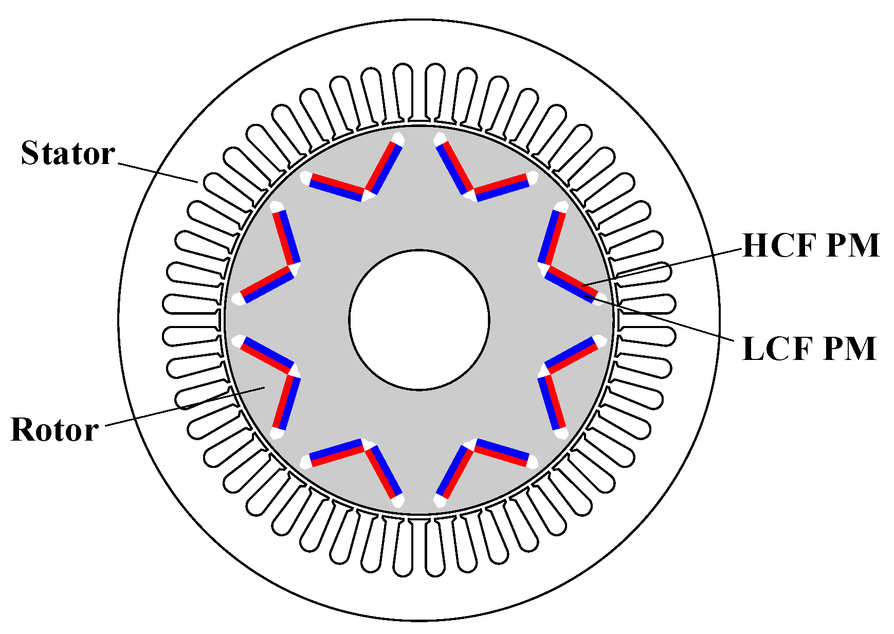
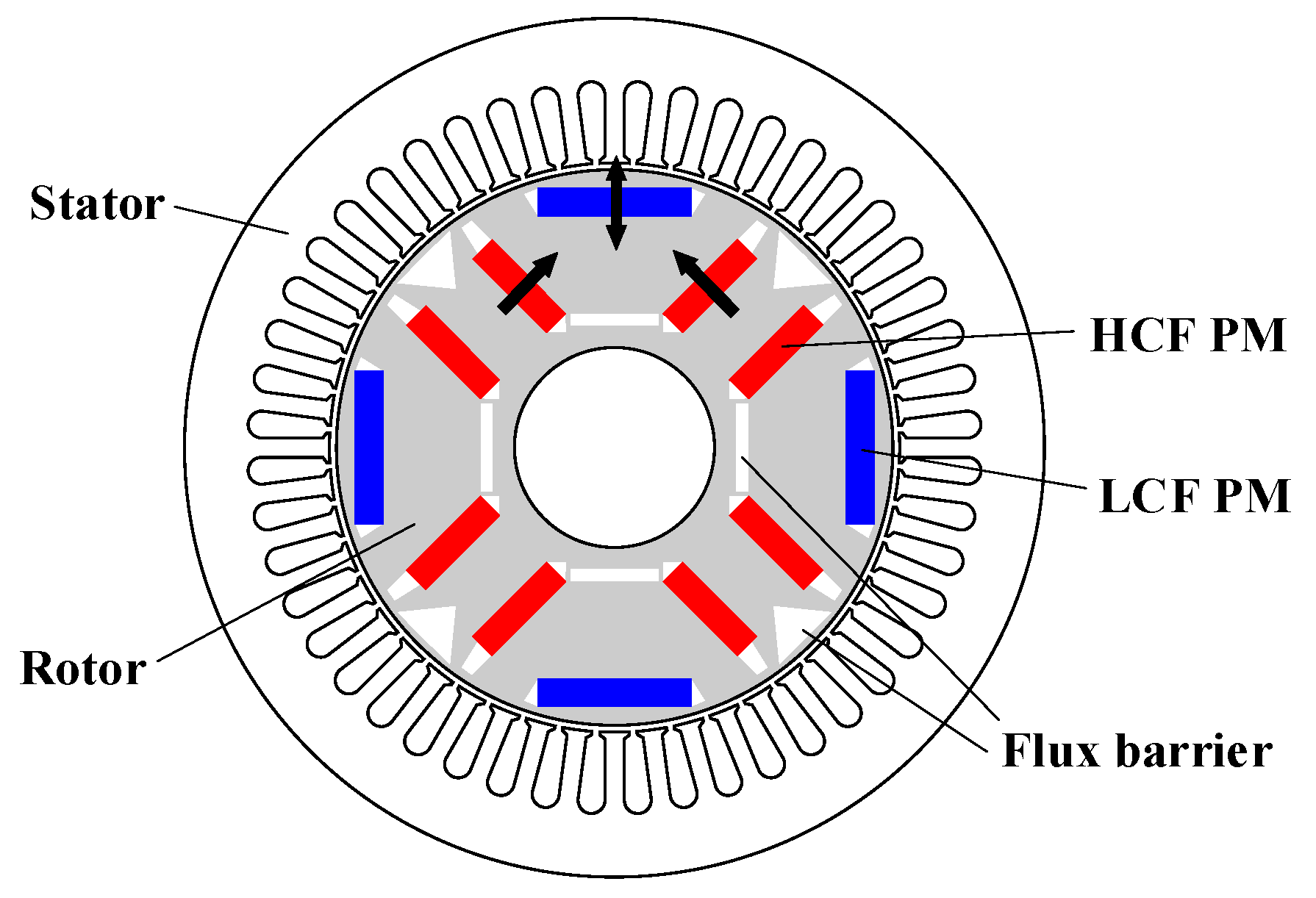
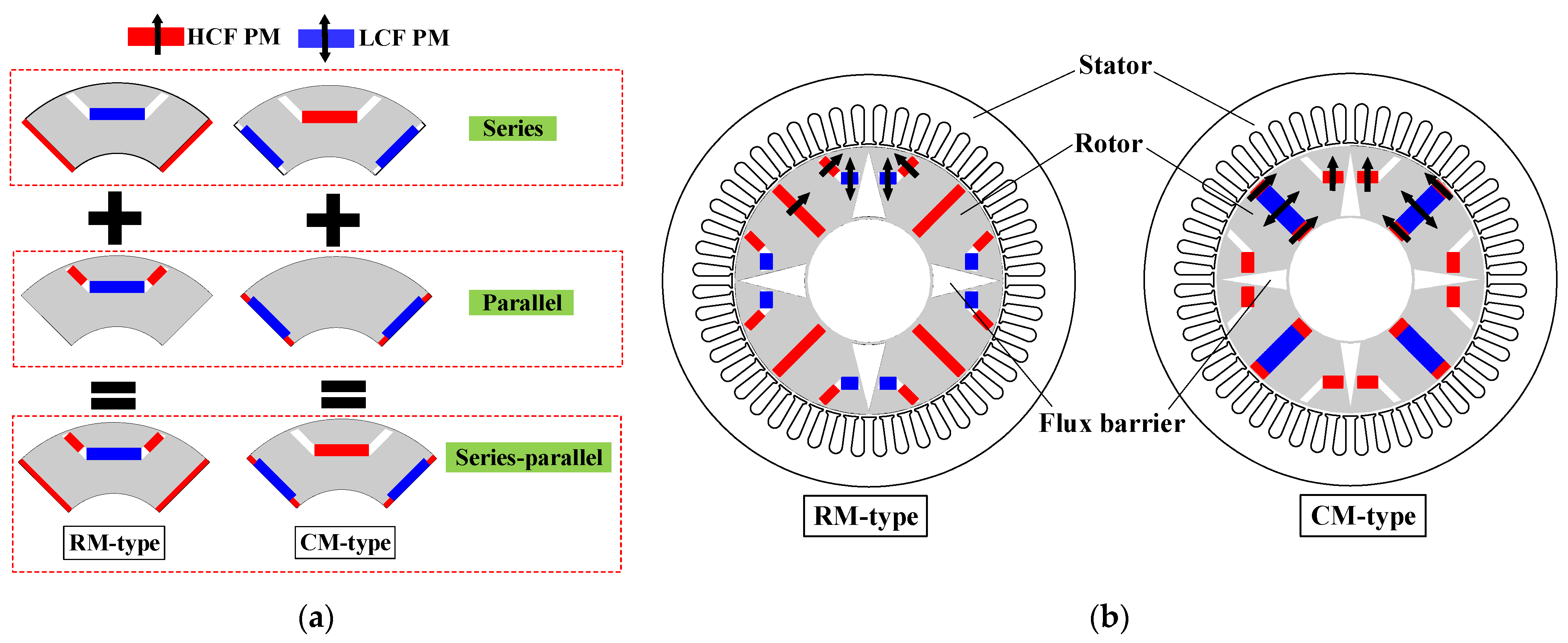
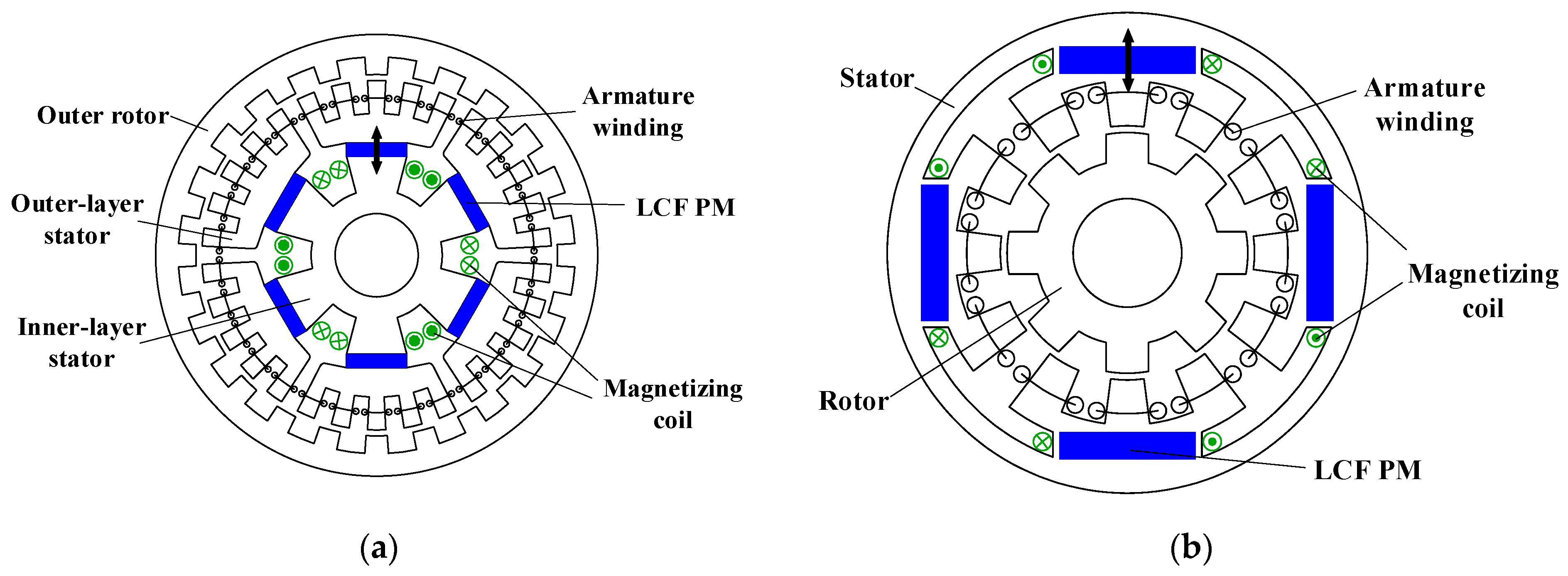
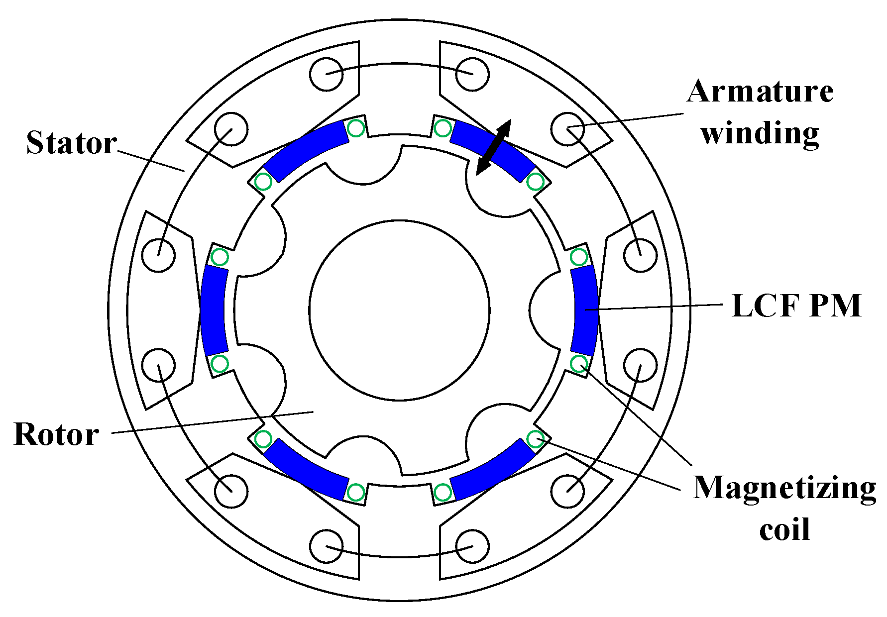
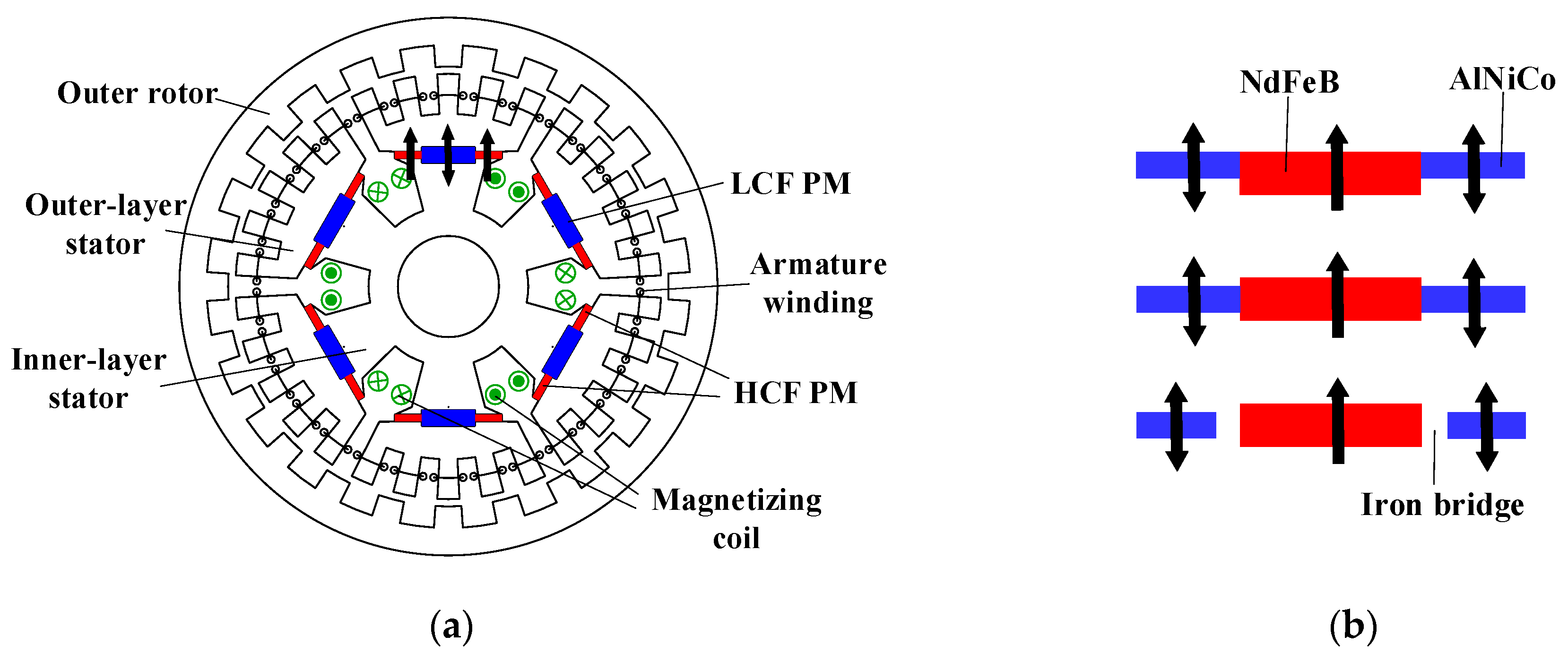
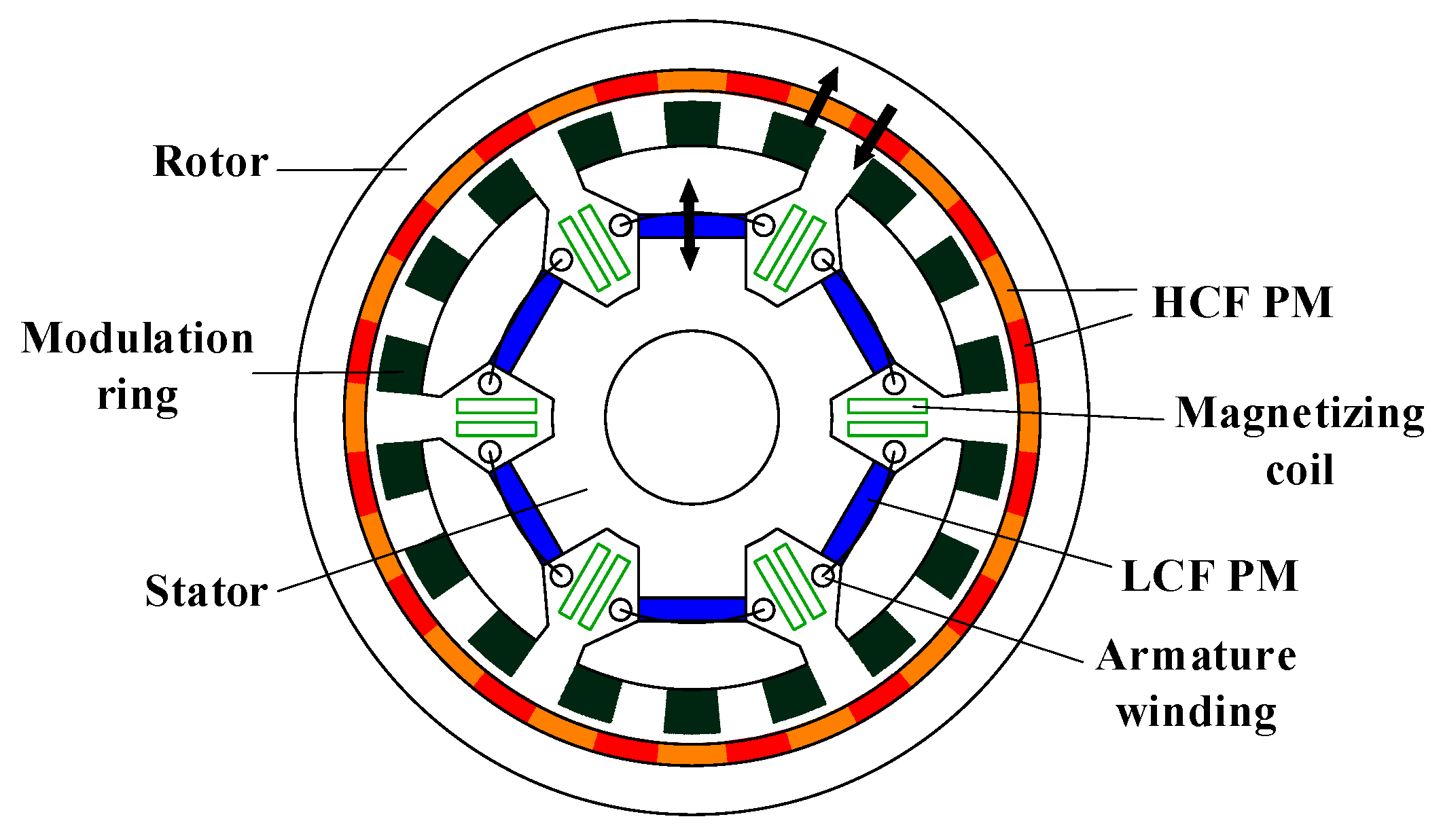
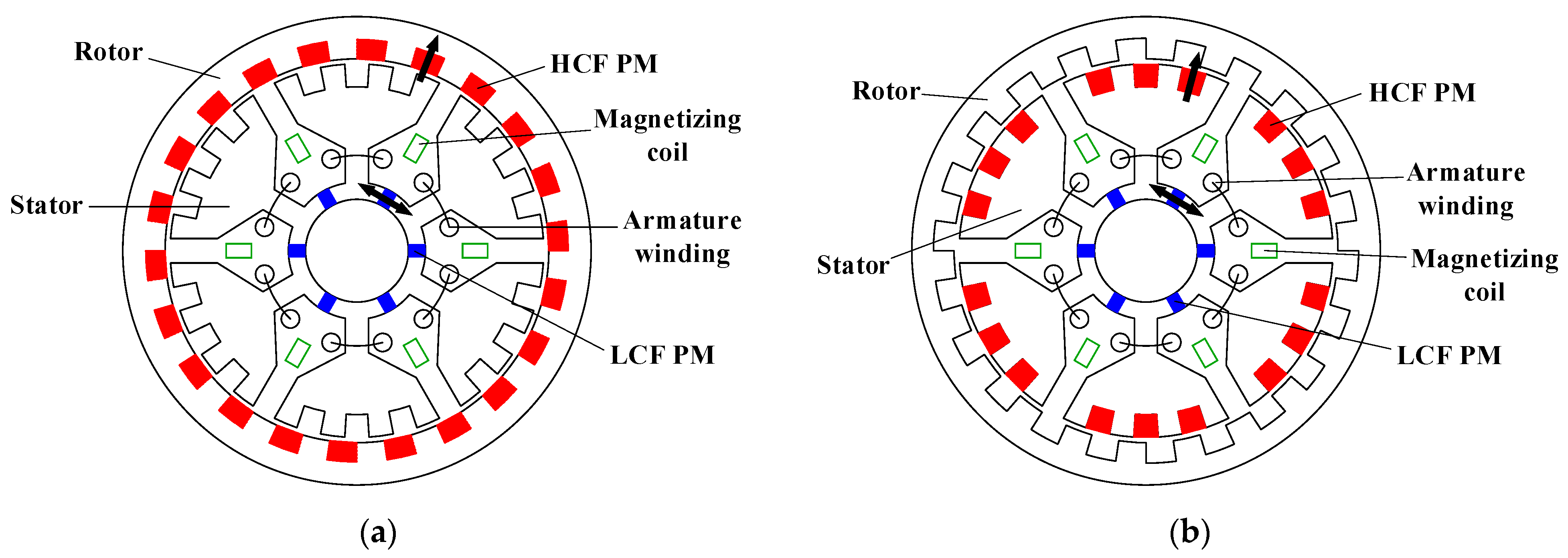
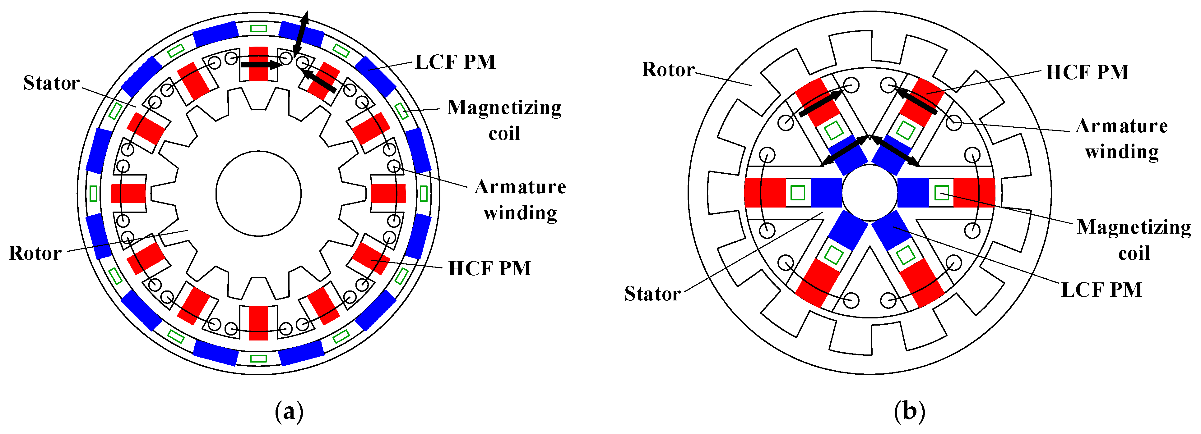
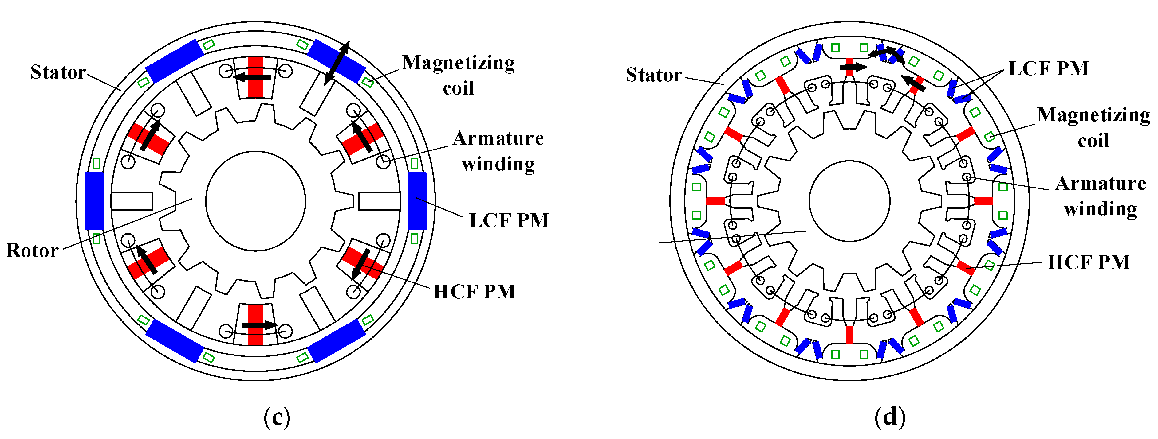
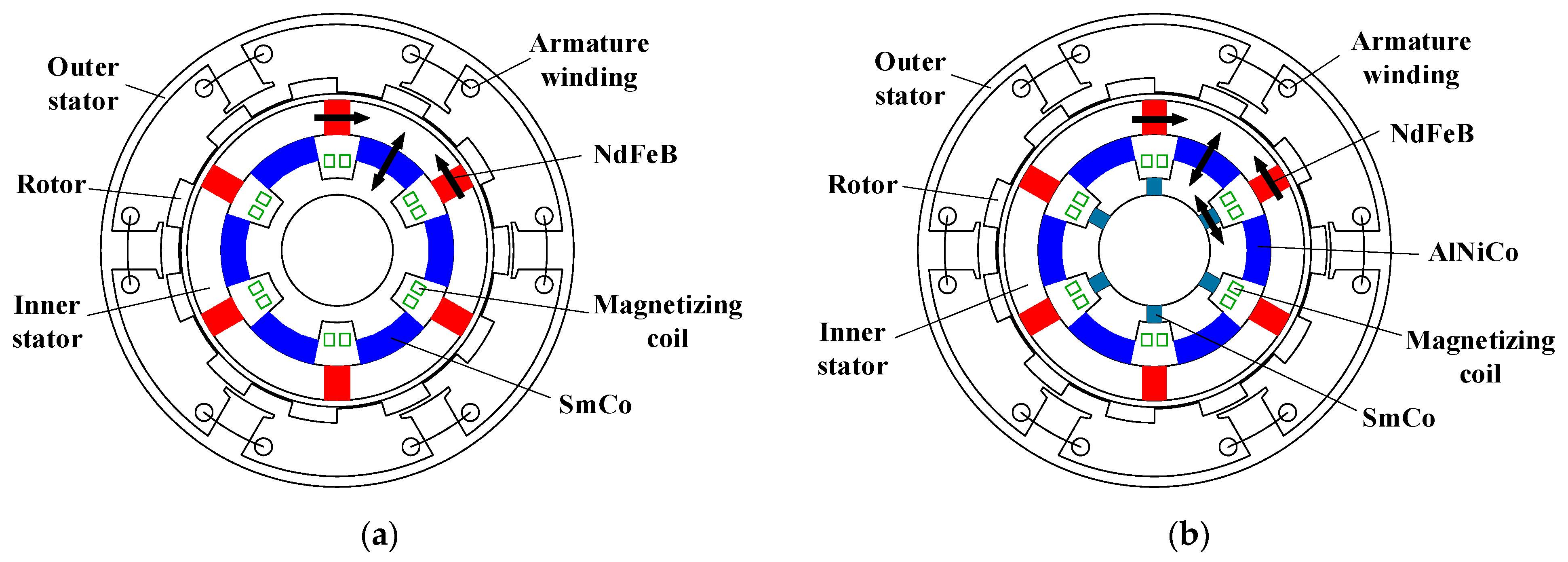
Publisher’s Note: MDPI stays neutral with regard to jurisdictional claims in published maps and institutional affiliations. |
© 2022 by the authors. Licensee MDPI, Basel, Switzerland. This article is an open access article distributed under the terms and conditions of the Creative Commons Attribution (CC BY) license (https://creativecommons.org/licenses/by/4.0/).