
A Structure Optimized Method Based on AFSA for Soft Magnetic Strips of Inner Double-Layer Shield for Wireless Power Transmission of EV


Abstract
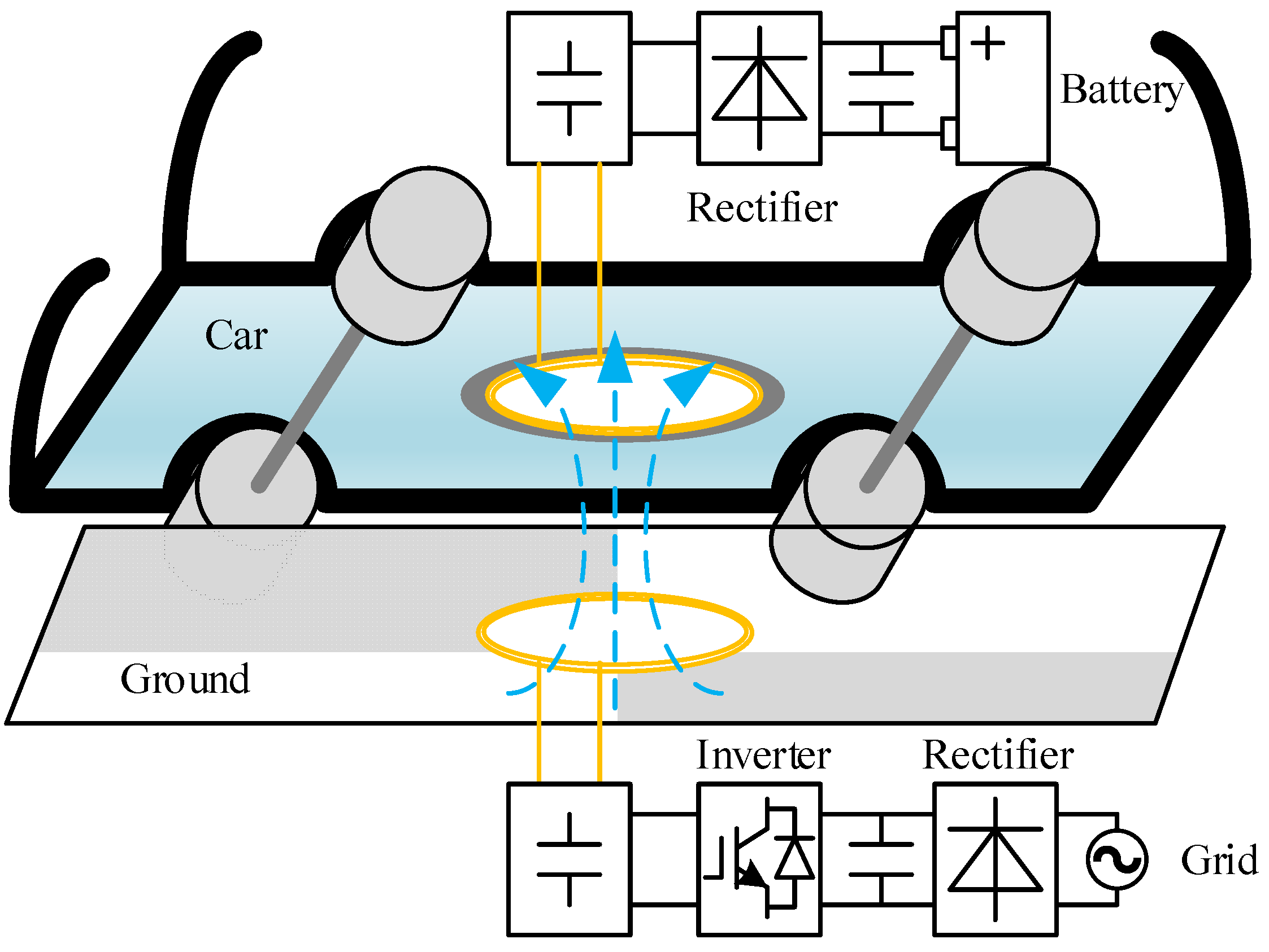
:1. Introduction
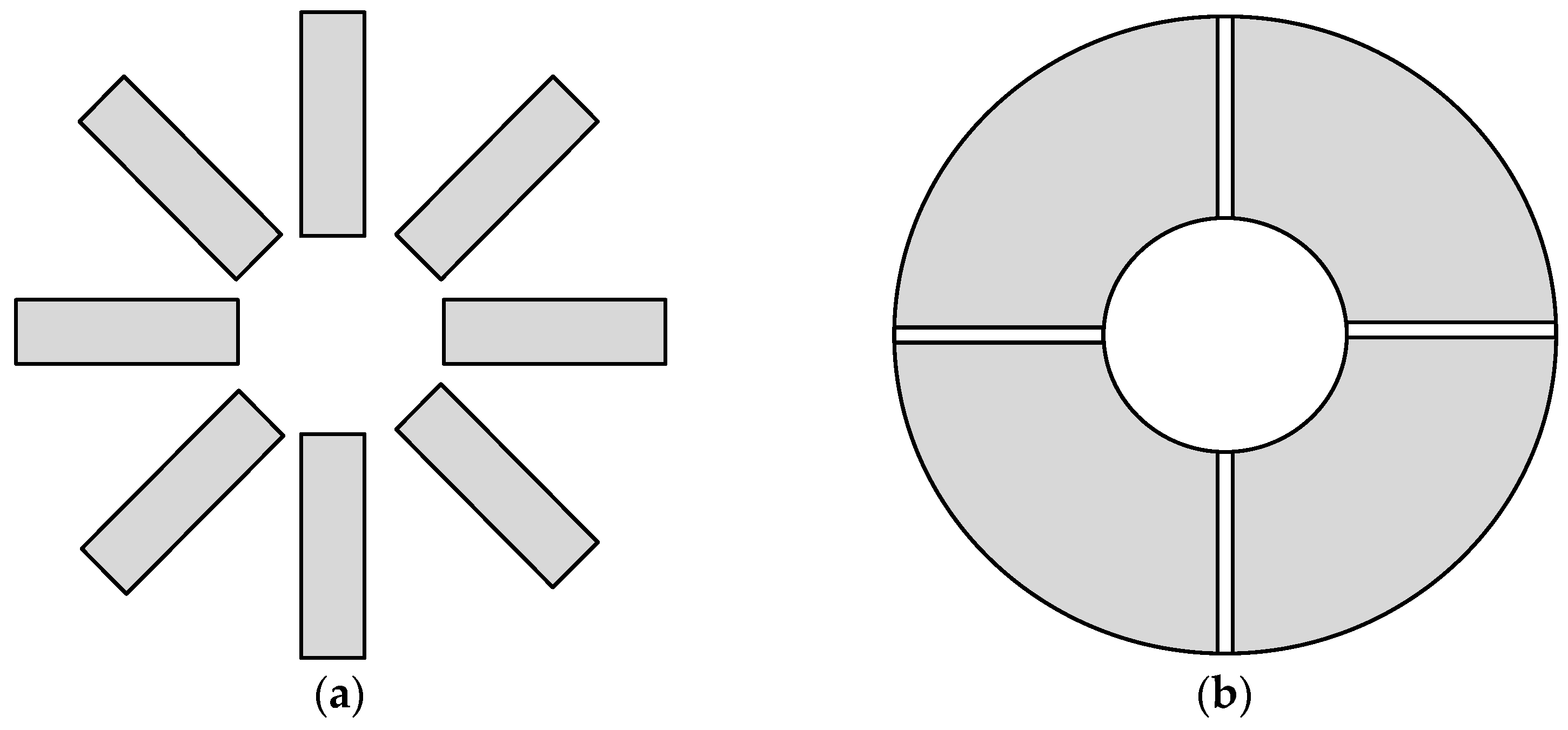
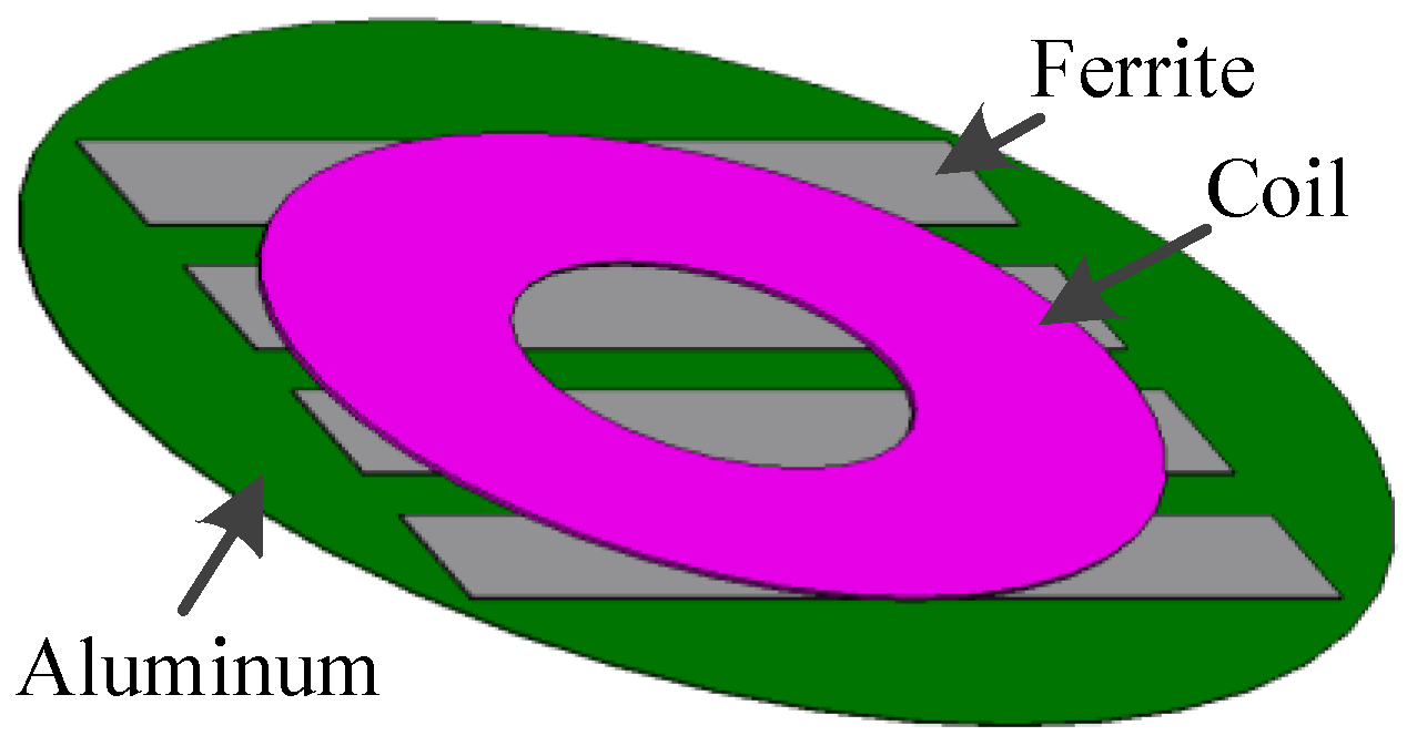
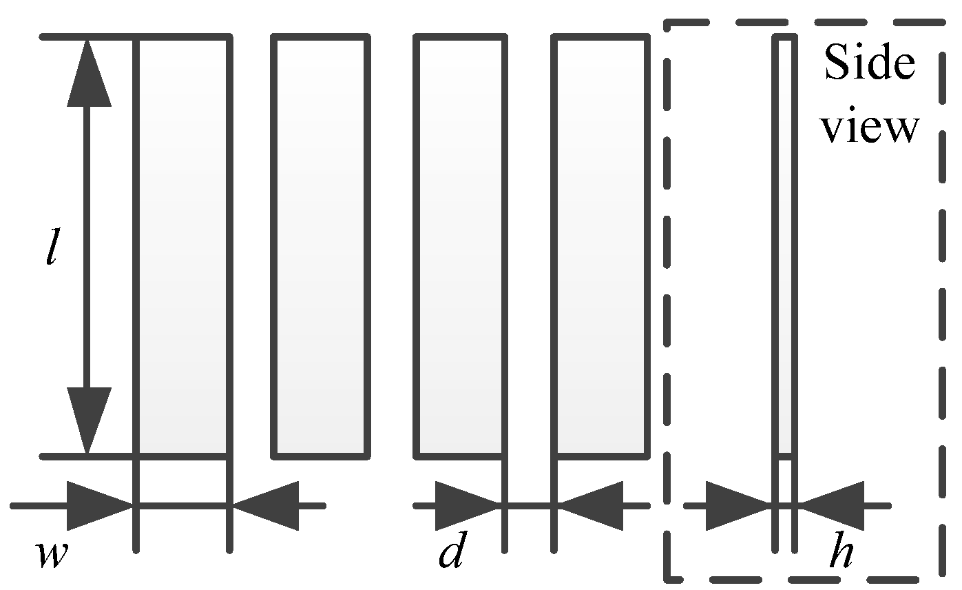
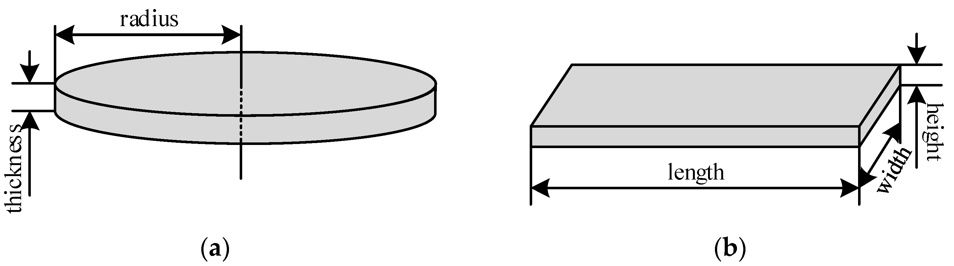
2. Structure of Shield
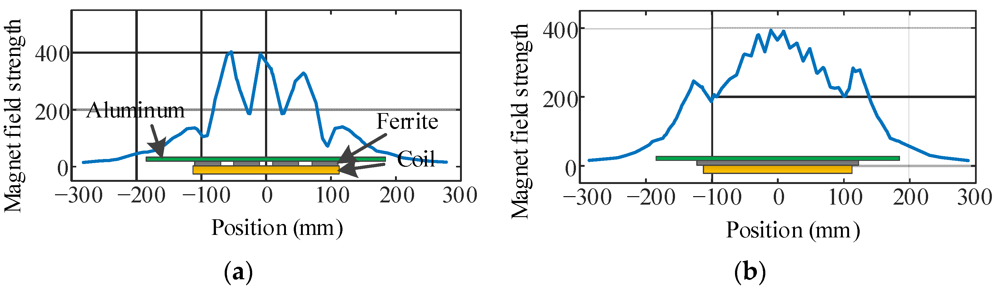
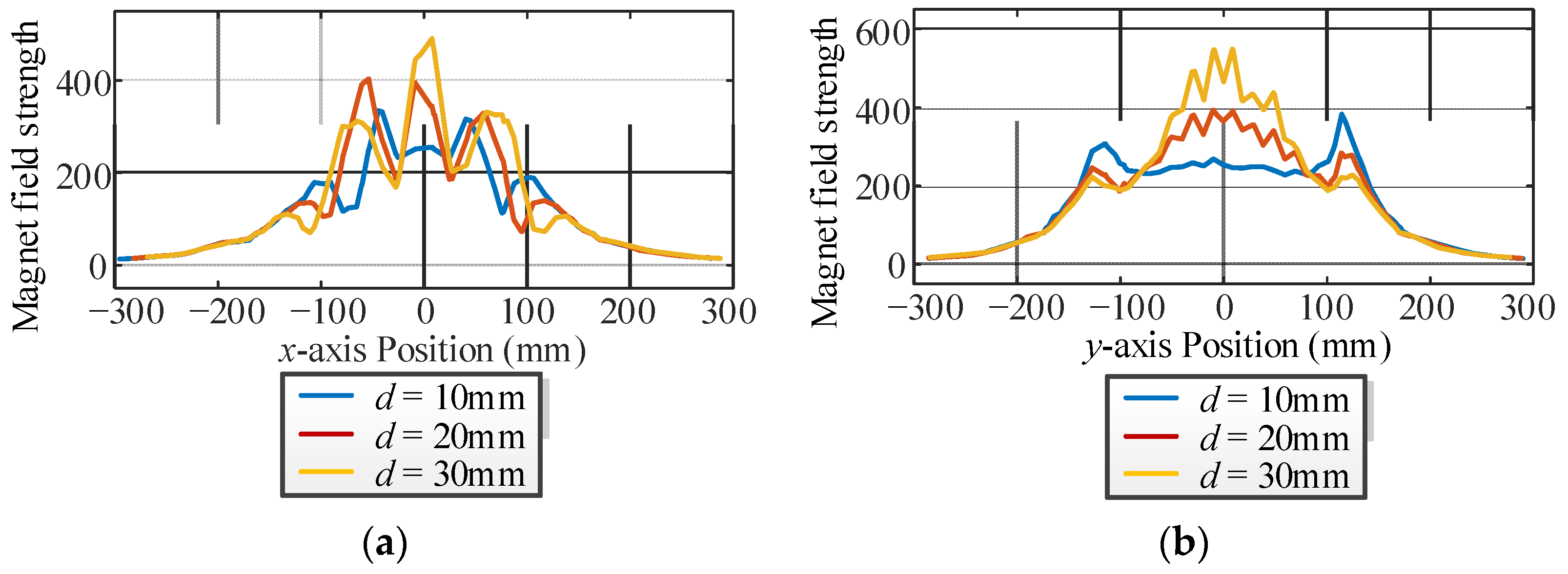
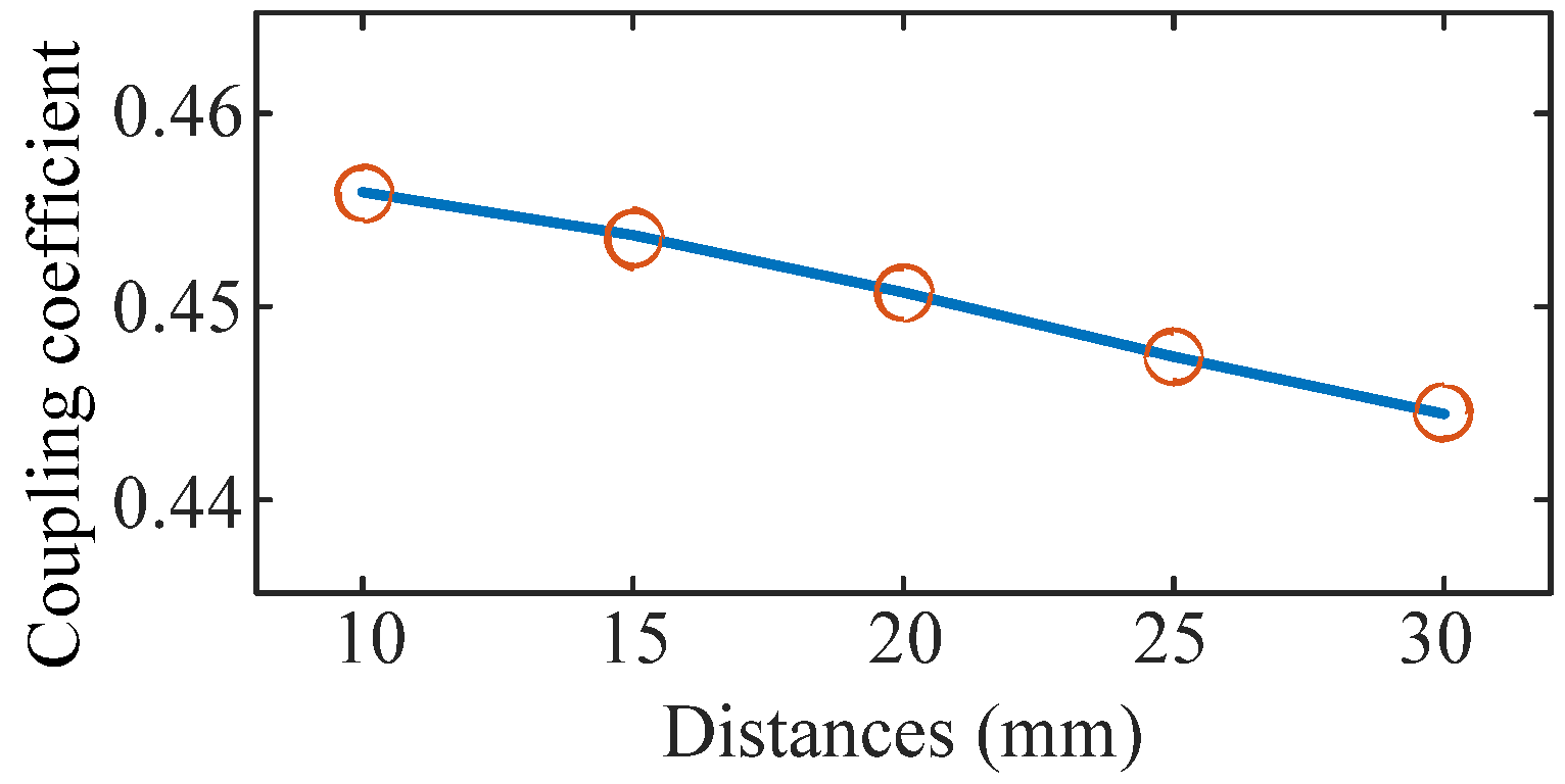
3. Structure Parameter Analysis
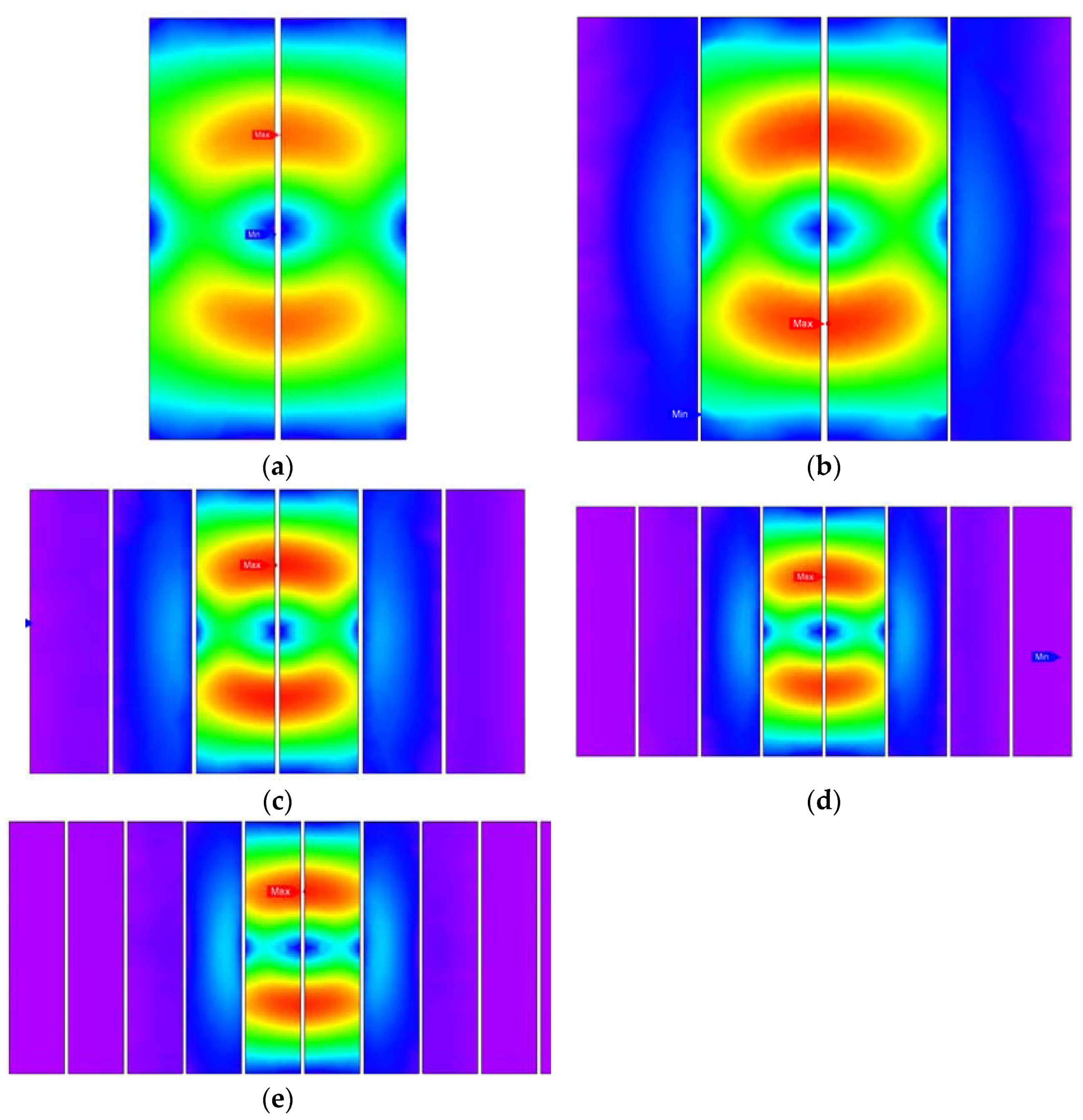
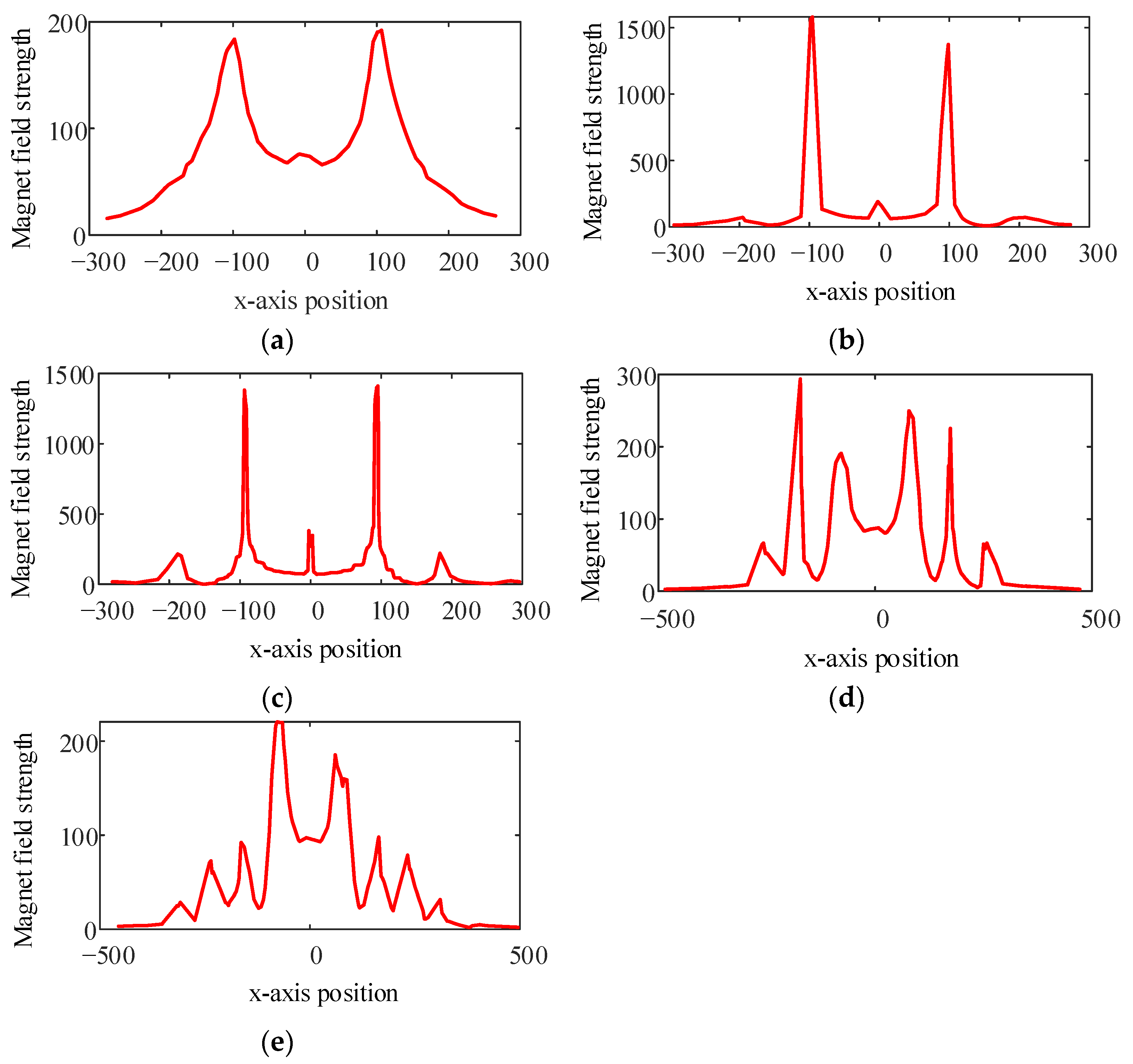
3.1. Distances between Strips d
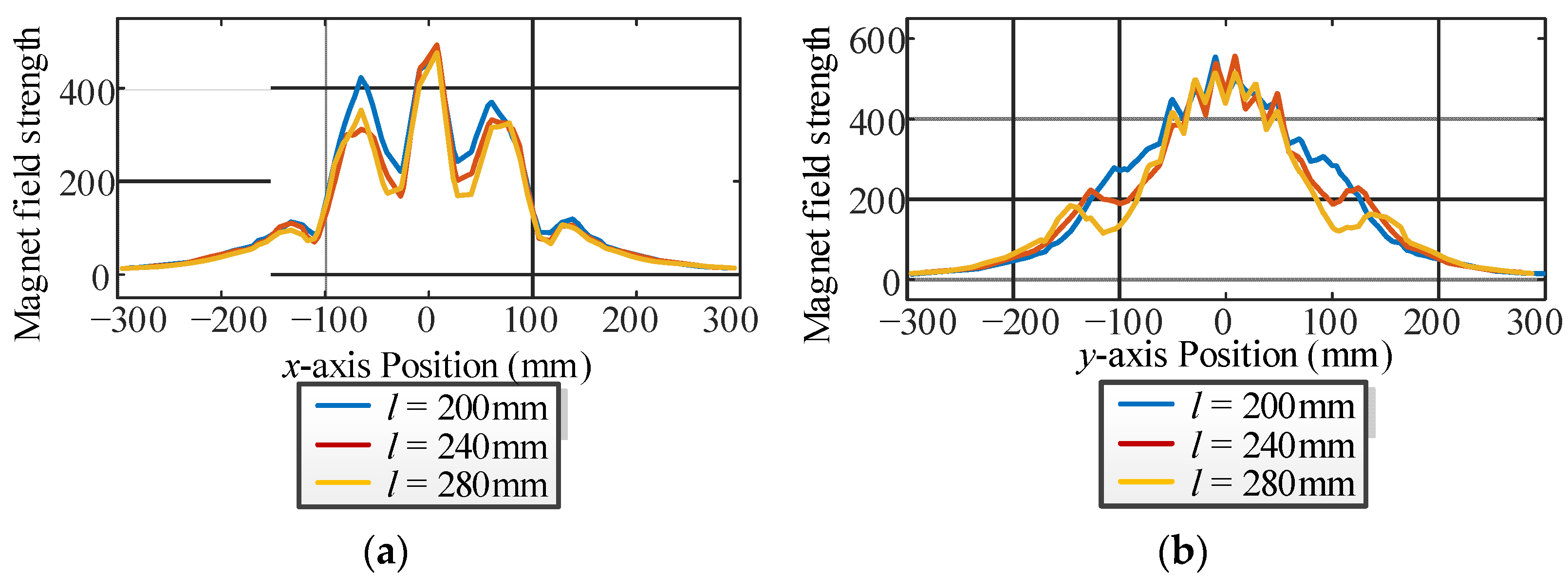
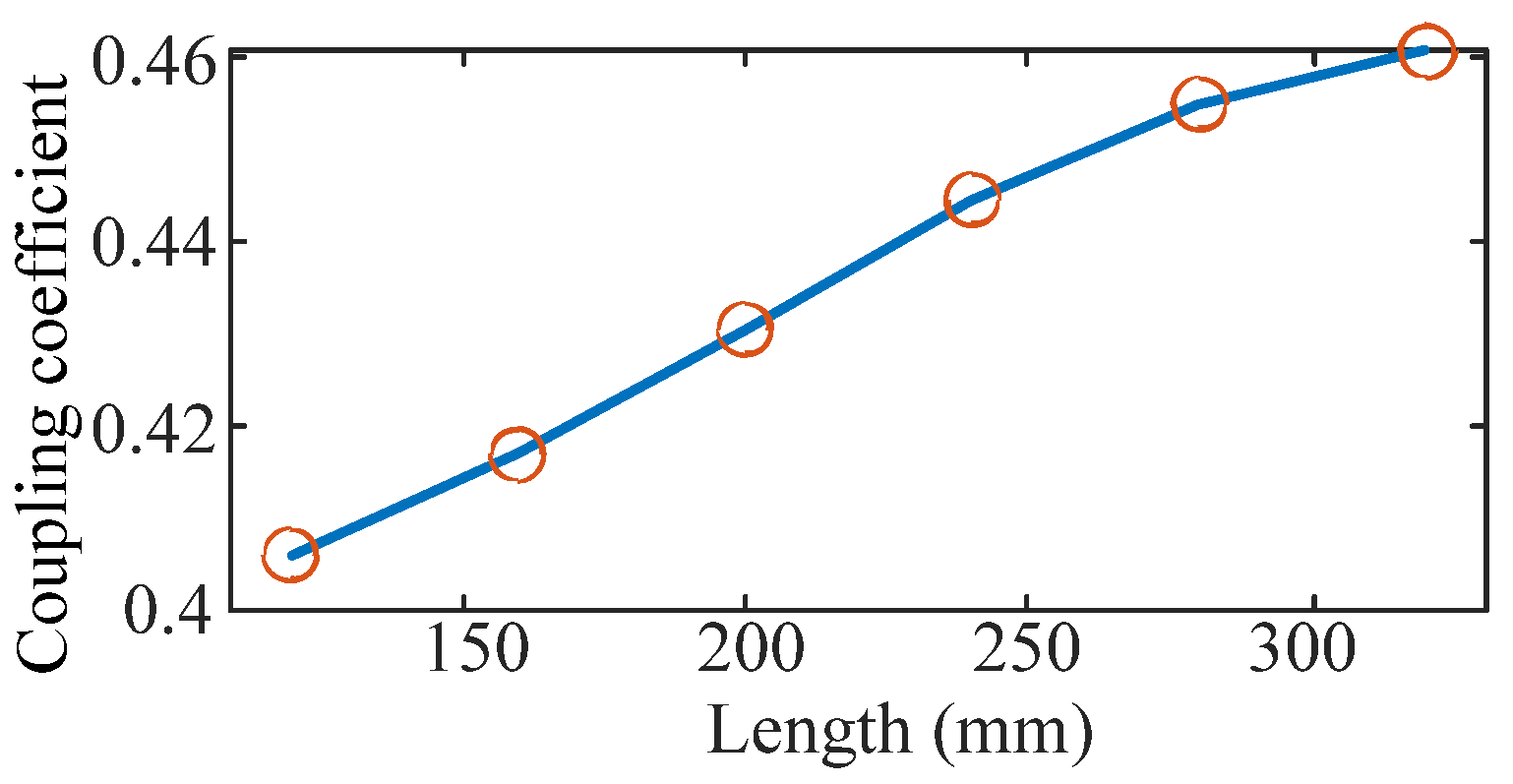
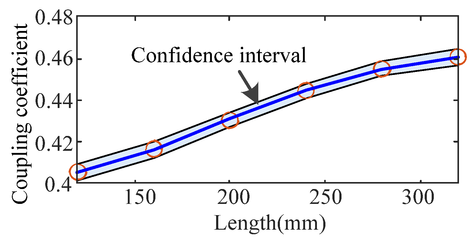
3.2. Length of Strips l
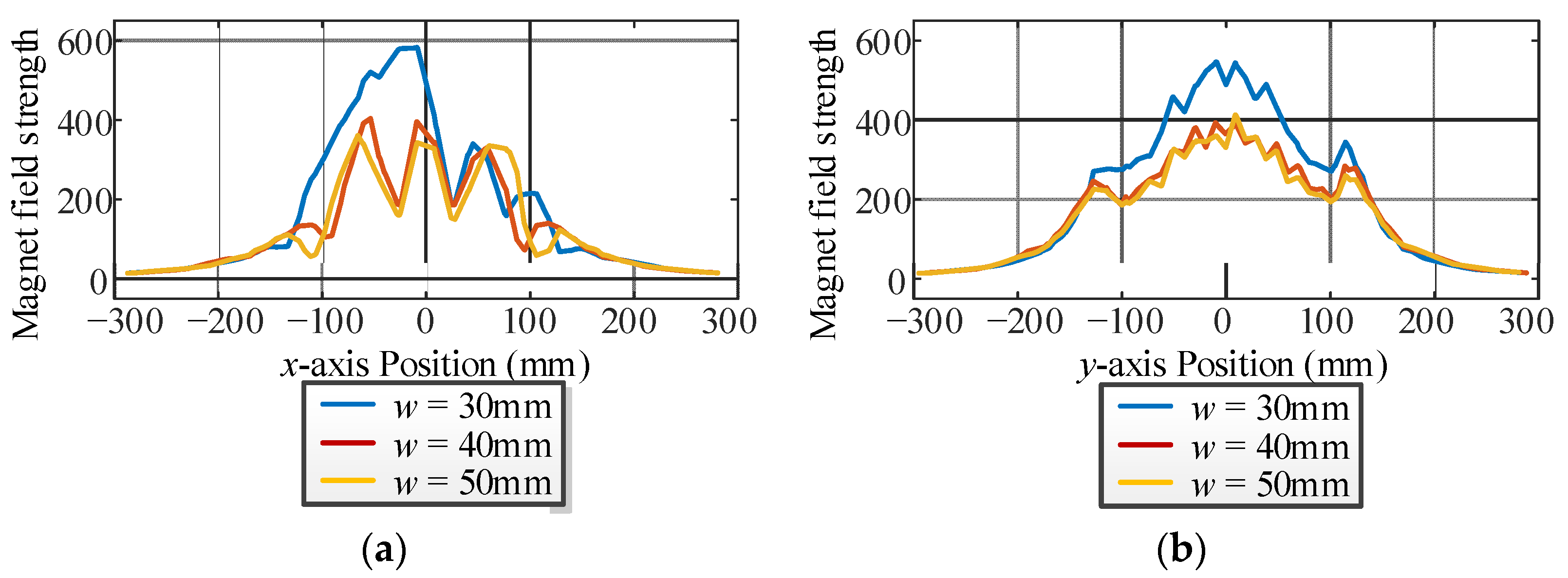
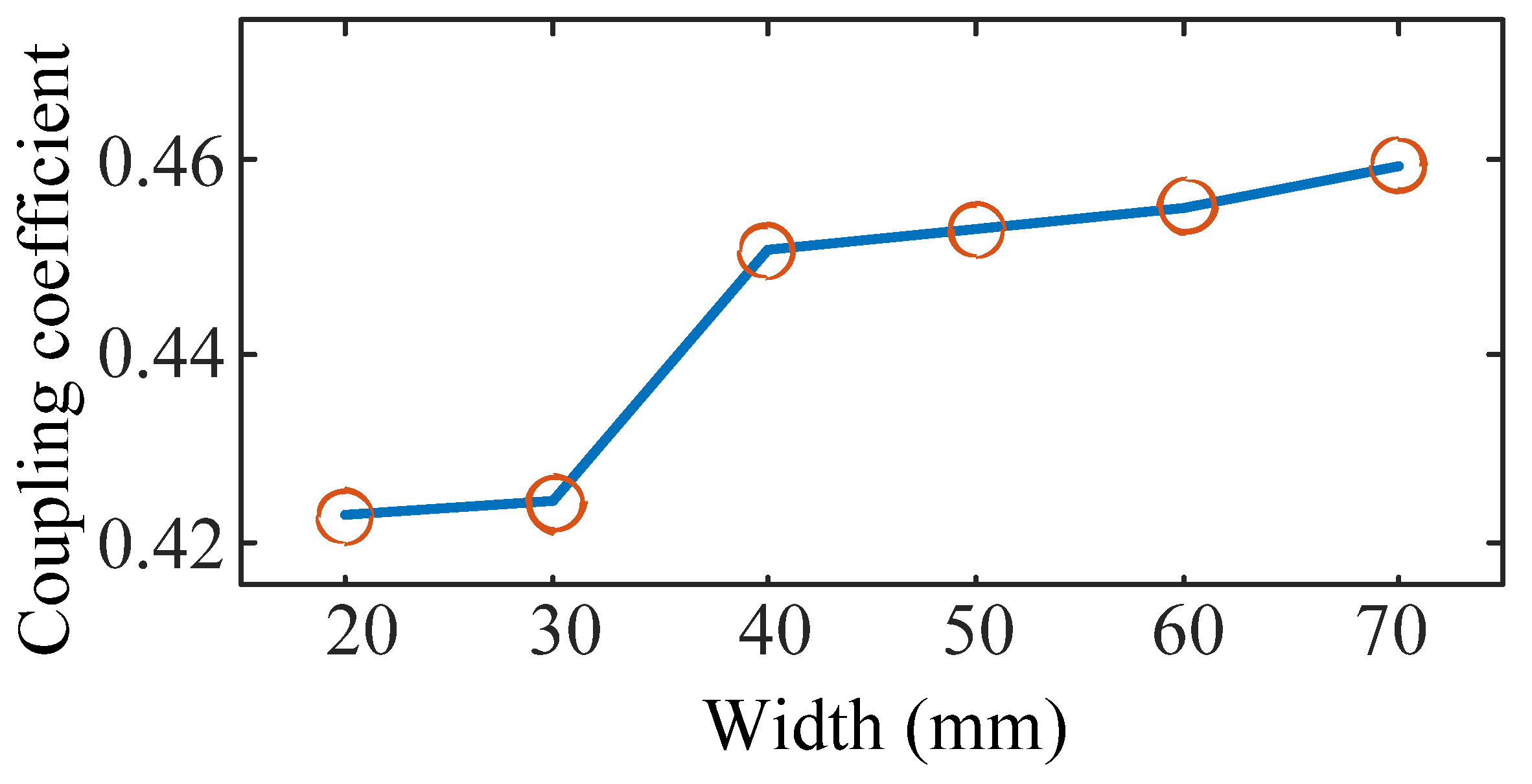
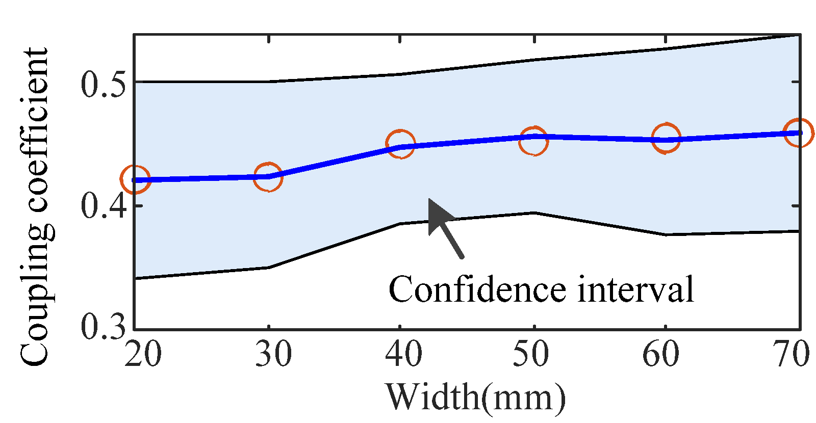
3.3. Width of Strips w
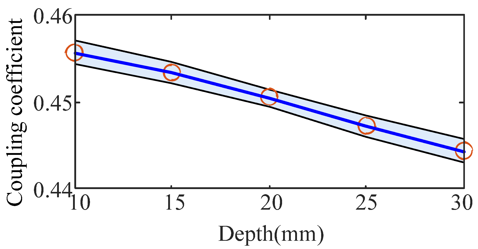
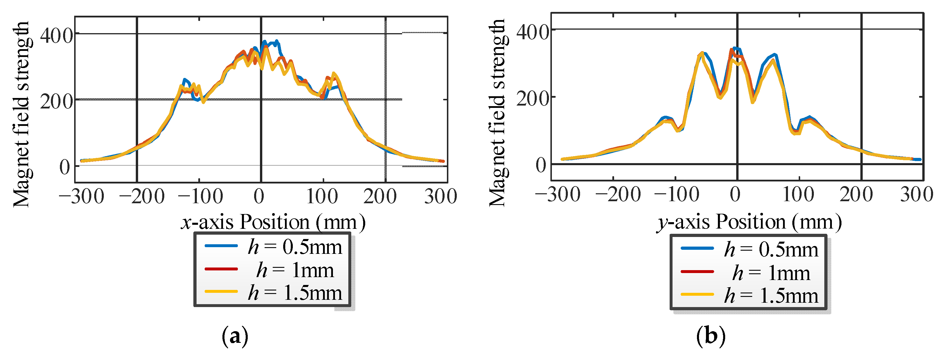
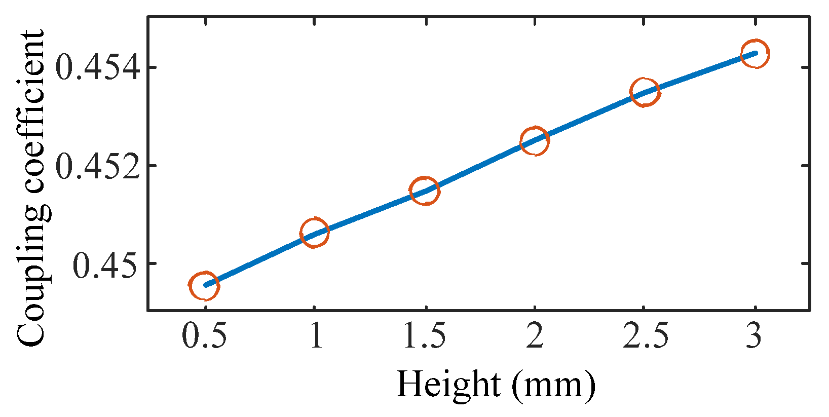
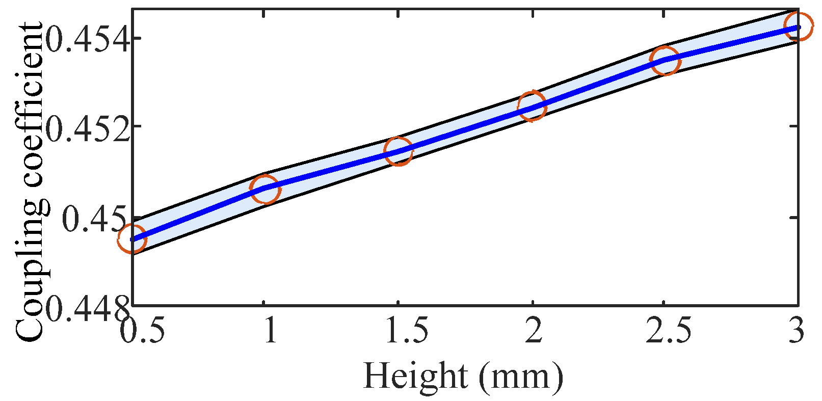
3.4. Height of Strips h
4. Optimized Method of Shield Structure
4.1. Correlation Analysis
4.2. AFSA-Optimized Structure Method
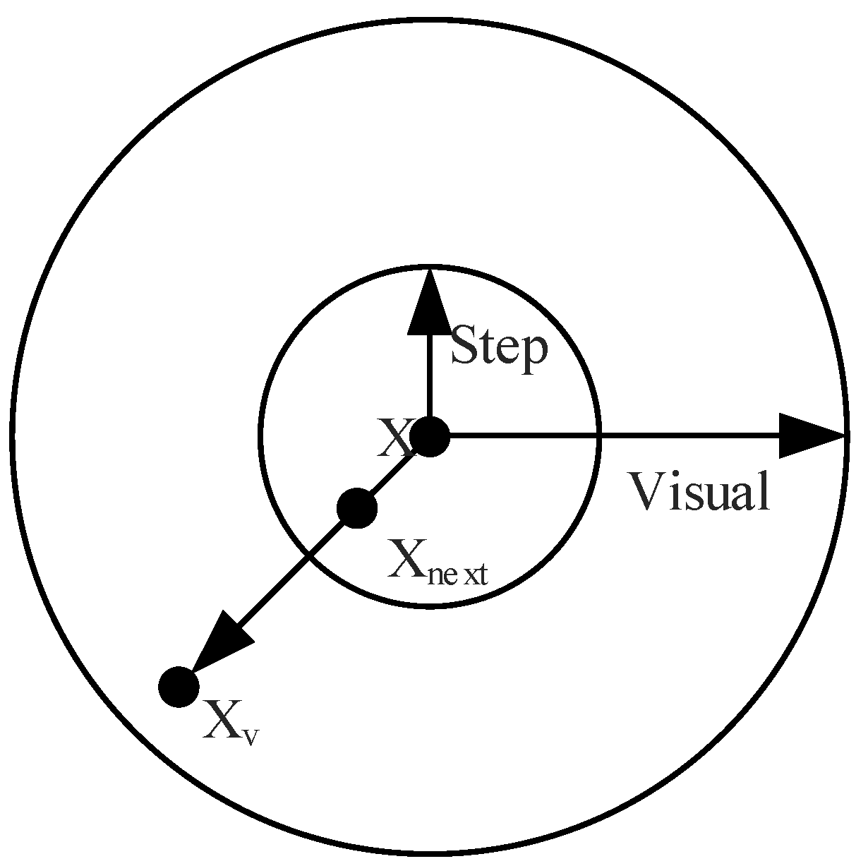
4.2.1. Basic Principle of AFSA
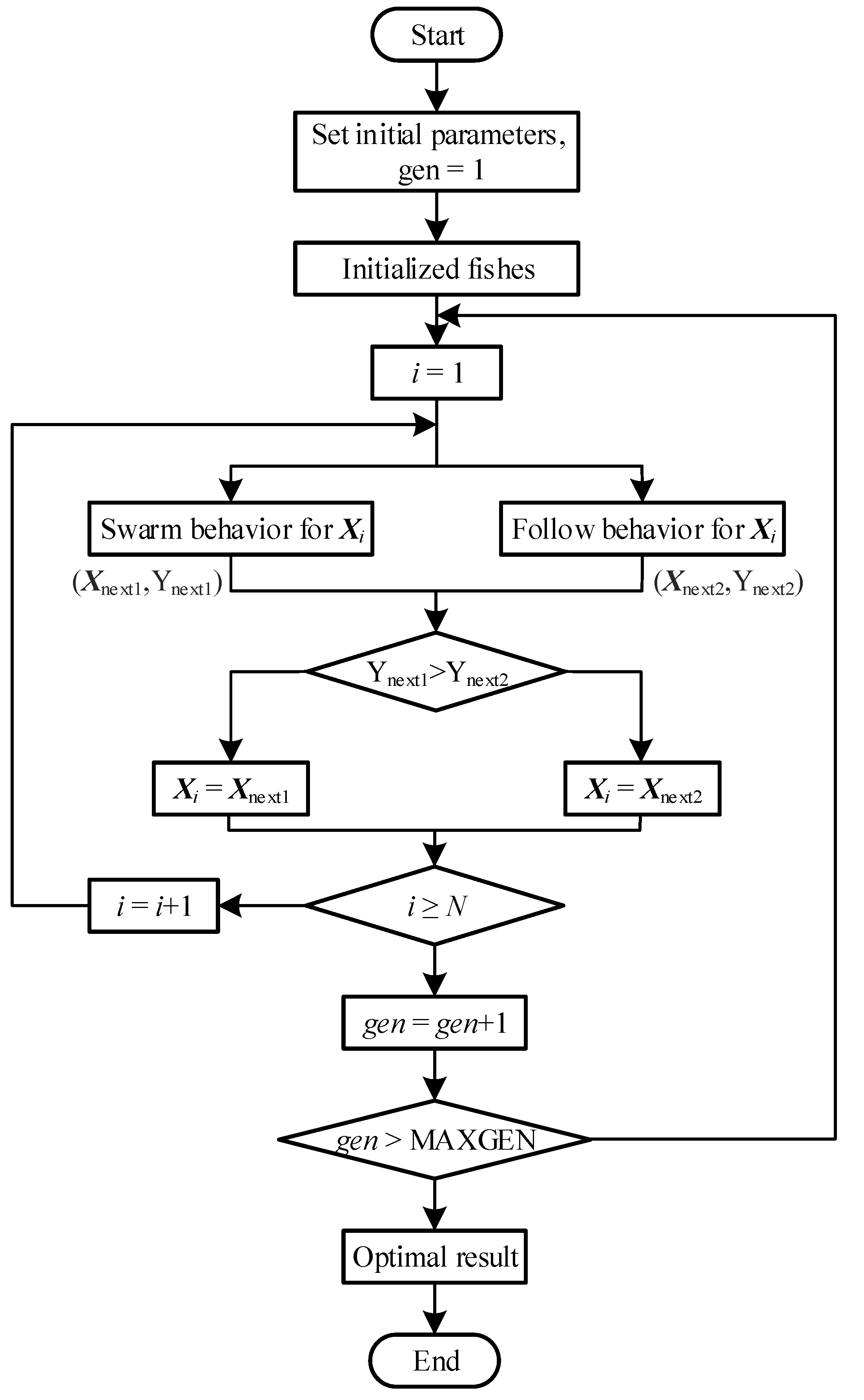
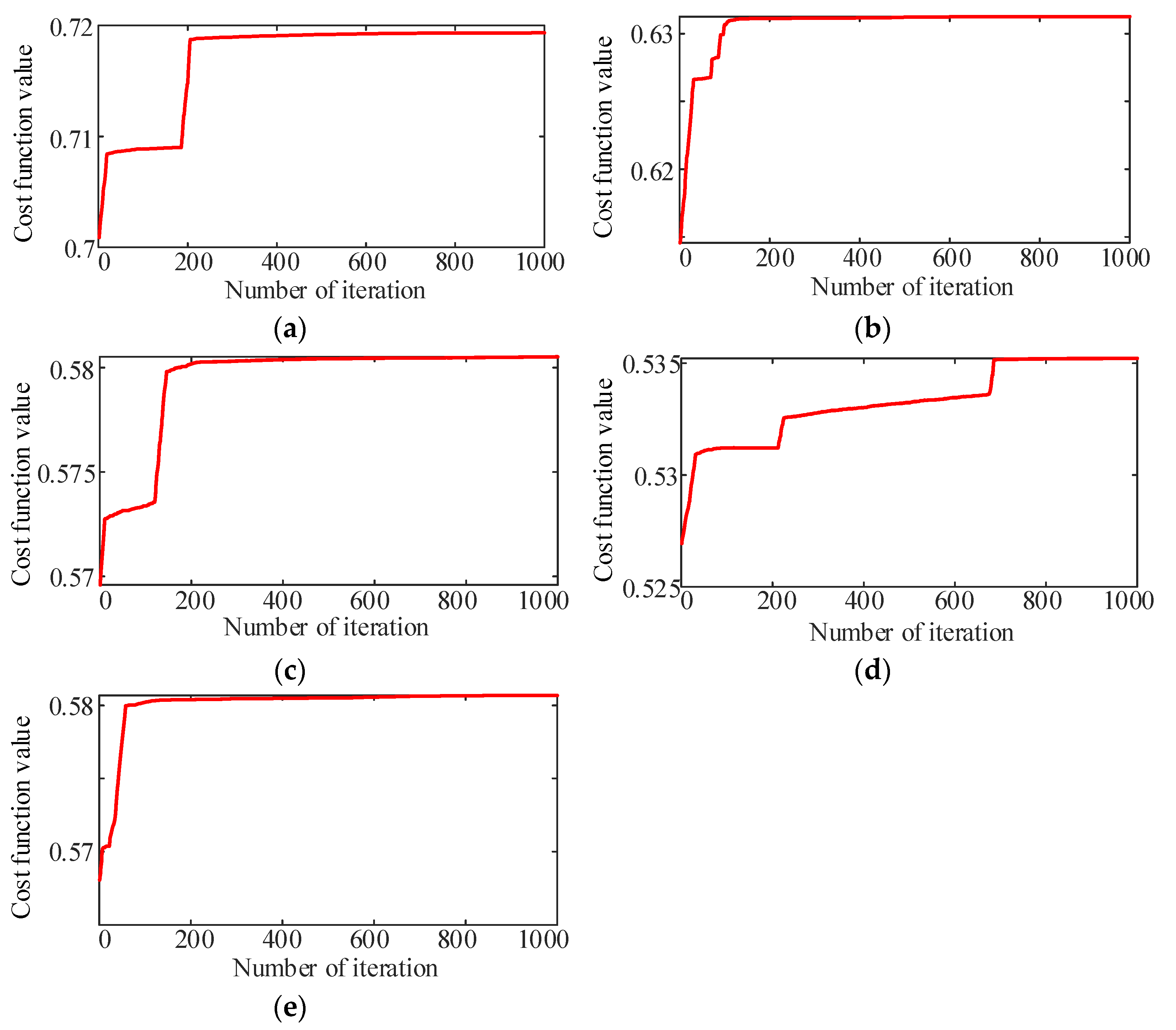
4.2.2. Optimization Process
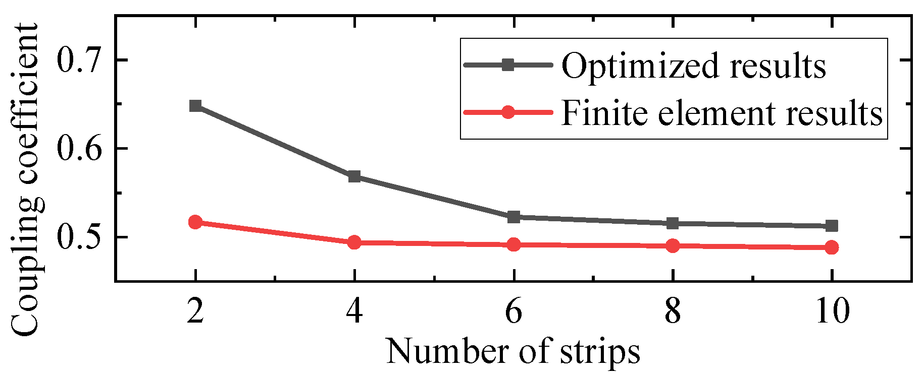
4.3. Validations by the Finite Element Analysis
4.4. Performance Comparisons
5. Some Discussions
6. Conclusions
Author Contributions
Funding
Institutional Review Board Statement
Informed Consent Statement
Data Availability Statement
Conflicts of Interest
References
- Chen, H.; Qian, Z.; Zhang, R.; Zhang, Z.; Wu, J.; Ma, H.; He, X. Modular Four-Channel 50 kW WPT System with Decoupled Coil Design for Fast EV Charging. IEEE Access 2021, 9, 136083–136093. [Google Scholar] [CrossRef]
- Zakerian, A.; Vaez-Zadeh, S.; Babaki, A. A Dynamic WPT System With High Efficiency and High Power Factor for Electric Vehicles. IEEE Trans. Power Electron. 2020, 35, 6732–6740. [Google Scholar] [CrossRef]
- Mohamed, A.A.S.; Lashway, C.R.; Mohammed, O. Modeling and Feasibility Analysis of Quasi-Dynamic WPT System for EV Applications. IEEE Trans. Transp. Electrif. 2017, 3, 343–353. [Google Scholar] [CrossRef]
- Babaki, A.; Vaez-Zadeh, S.; Zakerian, A.; Covic, G.A. Variable-Frequency Retuned WPT System for Power Transfer and Efficiency Improvement in Dynamic EV Charging With Fixed Voltage Characteristic. IEEE Trans. Energy Convers. 2021, 36, 2141–2151. [Google Scholar] [CrossRef]
- Xiang, L.; Li, X.; Tian, J.; Tian, Y. A Crossed DD Geometry and Its Double-Coil Excitation Method for Electric Vehicle Dynamic Wireless Charging Systems. IEEE Access 2018, 6, 45120–45128. [Google Scholar] [CrossRef]
- Zaheer, A.; Hao, H.; Covic, G.A.; Kacprzak, D. Investigation of Multiple Decoupled Coil Primary Pad Topologies in Lumped IPT Systems for Interoperable Electric Vehicle Charging. IEEE Trans. Power Electron. 2015, 30, 1937–1955. [Google Scholar] [CrossRef]
- Li, Y.; Zhao, J.; Yang, Q.; Liu, L.; Ma, J.; Zhang, X. A Novel Coil With High Misalignment Tolerance for Wireless Power Transfer. IEEE Trans. Magn. 2019, 55, 2800904. [Google Scholar] [CrossRef]
- Tejeda, A.; Kim, S.; Lin, F.Y.; Covic, G.A.; Boys, J.T. A Hybrid Solenoid Coupler for Wireless Charging Applications. IEEE Trans. Power Electron. 2019, 34, 5632–5645. [Google Scholar] [CrossRef]
- Kim, S.; Covic, G.A.; Boys, J.T. Tripolar Pad for Inductive Power Transfer Systems for EV Charging. IEEE Trans. Power Electron. 2017, 32, 5045–5057. [Google Scholar] [CrossRef]
- Ahmad, A.; Alam, M.S.; Mohamed, A.A.S. Design and Interoperability Analysis of Quadruple Pad Structure for Electric Vehicle Wireless Charging Application. IEEE Trans. Transp. Electrif. 2019, 5, 934–945. [Google Scholar] [CrossRef]
- Li, Y.; Jiang, S.; Liu, J.-M.; Ni, X.; Wang, R.; Ma, J.-N. Maximizing transfer distance for WPT via coupled magnetic resonances by coupling coils design and optimization. IEEE Access 2020, 8, 74157–74166. [Google Scholar] [CrossRef]
- Liu, F.; Ding, Z.; Fu, X.; Kennel, R.M. Parametric optimization of a three-phase MCR WPT system with cylinder-shaped coils oriented by soft-switching range and stable output power. IEEE Trans. Power Electron. 2020, 35, 1036–1044. [Google Scholar] [CrossRef]
- Wu, J.; Dai, X.; Gao, R.; Jiang, J. A coupling mechanism with multidegree freedom for bidirectional multistage WPT system. IEEE Trans. Power Electron. 2020, 36, 1376–1387. [Google Scholar] [CrossRef]
- Zhao, L.; Thrimawithana, D.J.; Madawala, U.K.; Hu, A.P.; Mi, C.C. A Misalignment-Tolerant Series-Hybrid Wireless EV Charging System With Integrated Magnetics. IEEE Trans. Power Electron. 2019, 34, 1276–1285. [Google Scholar] [CrossRef]
- Wang, X.; Xu, J.; Ma, H.; Yang, P. A High Efficiency LCC-S Compensated WPT System With Dual Decoupled Receive Coils and Cascaded PWM Regulator. IEEE Trans. Circuits Syst. II Express Briefs 2020, 67, 3142–3146. [Google Scholar] [CrossRef]
- Hwang, Y.J.; Jang, J.Y. Design and Analysis of a Novel Magnetic Coupler of an In-Wheel Wireless Power Transfer System for Electric Vehicles. Energies 2020, 13, 332. [Google Scholar] [CrossRef] [Green Version]
- Sun, Y.; Wei, Y.; Tian, Y. Phenomenon Analysis and Improvement of Magnetic Shield Fringe Effect on Wireless Power Transmission of EV. World Electr. Veh. J. 2021, 12, 252. [Google Scholar] [CrossRef]
- Wen, F.; Huang, X. Optimal Magnetic Field Shielding Method by Metallic Sheets in Wireless Power Transfer System. Energies 2016, 9, 733. [Google Scholar] [CrossRef]
- Budhia, M.; Boys, J.T.; Covic, G.A.; Huang, C.-Y. Development of a Single-Sided Flux Magnetic Coupler for Electric Vehicle IPT Charging Systems. IEEE Trans. Ind. Electron. 2013, 60, 318–328. [Google Scholar] [CrossRef]
- Zhang, W.; Yang, Q.; Li, Y.; Lin, Z.; Yang, M.; Mi, M. Comprehensive Analysis of Nanocrystalline Ribbon Cores in High-Power-Density Wireless Power Transfer Pads for Electric Vehicles. IEEE Trans. Magn. 2021, 58, 1–5. [Google Scholar] [CrossRef]
- Kvitkovic, J.; Patel, S.; Pamidi, S. Magnetic Shielding Characteristics of Hybrid High-Temperature Superconductor/Ferromagnetic Material Multilayer Shields. IEEE Trans. Appl. Supercond. 2017, 27, 4700705. [Google Scholar] [CrossRef]
- Feng, H.; Tavakoli, R.; Onar, O.C.; Pantic, Z. Advances in High-Power Wireless Charging Systems: Overview and Design Considerations. IEEE Trans. Transp. Electrif. 2020, 6, 886–919. [Google Scholar] [CrossRef]
- Wei, Y.; Tian, Y. A Weighting factor online tuning method based PSO algorithm for MPTC strategy of PMSM. In Proceedings of the 2021 IEEE 12th Annual Information Technology, Electronics and Mobile Communication Conference (IEMCON), Vancouver, BC, Canada, 27–30 October 2021. [Google Scholar]
- Wang, X.; Xu, J.; Mao, M.; Ma, H. An LCL-Based SS Compensated WPT Converter With Wide ZVS Range and Integrated Coil Structure. IEEE Trans. Ind. Electron. 2021, 68, 4882–4893. [Google Scholar] [CrossRef]
- Li, Y.; Lin, T.; Mai, R.; Huang, L.; He, Z. Compact Double-Sided Decoupled Coils-Based WPT Systems for High-Power Applications: Analysis, Design, and Experimental Verification. IEEE Trans. Transp. Electrif. 2018, 4, 64–75. [Google Scholar] [CrossRef]


| Permeability | Resistivity | Saturation Magnetic Flux Density | Working Frequency Range | |
|---|---|---|---|---|
| Aluminum | 0 H/m | 26.55 nΩ | - | >100 kHz |
| Mn-Zn Ferrite | 2500 H/m | ∞ | 0.5 T | 1 kHz~10 MHz |
| Coefficients | Values | Coefficients | Values |
|---|---|---|---|
| ad1 | 6.267 × 10⁻⁷ | aw1 | 1.063 × 10⁻⁷ |
| ad2 | −4.23 × 10⁻⁵ | aw2 | −1.953 × 10⁻⁵ |
| ad3 | 3.11 × 10⁻⁴ | aw3 | 0.0013 |
| ad4 | 0.456 | aw4 | −0.0324 |
| al1 | 1.101 × 10⁻¹¹ | aw5 | 0.7049 |
| al2 | −1.695 × 10⁻⁸ | ah1 | −2.084 × 10⁻⁴ |
| al3 | 7.431 × 10⁻⁶ | ah2 | 0.0014 |
| al4 | −9.299 × 10⁻⁴ | ah3 | −0.0034 |
| al5 | 0.437 | ah4 | 0.0051 |
| ah5 | 0.4477 |
| Distances | Length | Width | Height | |
|---|---|---|---|---|
| Pearson correlation | 0.993 | 0.998 | 0.928 | 0.999 |
| Pearson significance | 0.000 | 0.000 | 0.008 | 0.000 |
| Labels | Value | Labels | Value |
|---|---|---|---|
| Number of fishes | 100 | Visual distance | 1 |
| Maximum iteration | 1000 | Congestion factor | 0.618 |
| Maximum probe | 100 | Step | 0.1 |
| Length | Height | Width | Distances | Volume | Coupling Coefficient | |
|---|---|---|---|---|---|---|
| N = 2 | 337.01 mm | 3.01 mm | 100.0 mm | 5.02 mm | 2.08 × 105 mm3 | 0.6474 |
| N = 4 | 326.52 mm | 3.01 mm | 86.54 mm | 5.00 mm | 3.55 × 105 mm3 | 0.5716 |
| N = 6 | 317.17 mm | 2.99 mm | 87.78 mm | 5.00 mm | 5.24 × 105 mm3 | 0.5225 |
| N = 8 | 341.73 mm | 3.00 mm | 80.02 mm | 5.00 mm | 6.92 × 105 mm3 | 0.5152 |
| N = 10 | 333.46 mm | 3.00 mm | 73.21 mm | 5.00 mm | 7.78 × 105 mm3 | 0.5123 |
| Primary Coil Inductance | Secondary Coil Inductance | Mutual Inductance | Coupling Coefficient | |
|---|---|---|---|---|
| N = 2 | 92.222 μH | 76.827 μH | 43.558 μH | 0.517 |
| N = 4 | 92.503 μH | 76.338 μH | 41.505 μH | 0.494 |
| N = 6 | 91.754 μH | 75.292 μH | 40.812 μH | 0.491 |
| N = 8 | 91.571 μH | 74.717 μH | 40.576 μH | 0.490 |
| N = 10 | 90.764 μH | 73.641 μH | 39.901 μH | 0.488 |
| AFSA | NSGA-II | PSO | |
|---|---|---|---|
| Length | 326.52 mm | 330.69 mm | 334.52 mm |
| Height | 3.01 mm | 3.00 mm | 2.99 mm |
| Width | 86.54 mm | 73.21 mm | 75.19 mm |
| Distance | 5.00 mm | 5.00 mm | 5.00 mm |
| Volume | 3.55 × 105 mm3 | 3.09 × 105 mm3 | 3.17 × 105 mm3 |
| Coupling coefficient | 0.5716 | 0.5123 | 0.5178 |
| Calculation time | 8.2541 s | 7.7048 s | 8.2207 s |
| Estimated error | 13.576% | 14.651% | 14.843% |
Publisher’s Note: MDPI stays neutral with regard to jurisdictional claims in published maps and institutional affiliations. |
© 2022 by the authors. Licensee MDPI, Basel, Switzerland. This article is an open access article distributed under the terms and conditions of the Creative Commons Attribution (CC BY) license (https://creativecommons.org/licenses/by/4.0/).
Share and Cite
Sun, Y.; Wei, Y.; Tian, Y. A Structure Optimized Method Based on AFSA for Soft Magnetic Strips of Inner Double-Layer Shield for Wireless Power Transmission of EV. World Electr. Veh. J. 2022, 13, 49. https://doi.org/10.3390/wevj13030049
Sun Y, Wei Y, Tian Y. A Structure Optimized Method Based on AFSA for Soft Magnetic Strips of Inner Double-Layer Shield for Wireless Power Transmission of EV. World Electric Vehicle Journal. 2022; 13(3):49. https://doi.org/10.3390/wevj13030049
Chicago/Turabian StyleSun, Yening, Yao Wei, and Yi Tian. 2022. "A Structure Optimized Method Based on AFSA for Soft Magnetic Strips of Inner Double-Layer Shield for Wireless Power Transmission of EV" World Electric Vehicle Journal 13, no. 3: 49. https://doi.org/10.3390/wevj13030049
APA StyleSun, Y., Wei, Y., & Tian, Y. (2022). A Structure Optimized Method Based on AFSA for Soft Magnetic Strips of Inner Double-Layer Shield for Wireless Power Transmission of EV. World Electric Vehicle Journal, 13(3), 49. https://doi.org/10.3390/wevj13030049