Abstract
In this paper, improved electrothermal models of the power diode and IGBT have been developed. The main local physical effects have been considered. The proposed models are able to deal with electrical and thermal effects. The models were confirmed by comparison with other models having similar characteristics for different circuits and different temperatures. The developed models are implemented in a traction unit to study the electrothermal performance in an electric vehicle system. The models were implemented in the Pspice circuit simulation platform using standard Pspice components and analog behavior modeling (ABM) blocks. The switching performance of the diode and the IGBT have been studied under the influence of different circuit elements in order to study and estimate the on-state and switching losses pre-required for the design of various topologies of converters and inverters. The comparison shows that these models are simple, configurable with the electrical circuit simulator software. They are better able to predict the main circuit parameters needed for power electronics design. Transient thermal responses have been demonstrated for single pulse and repetition modes. The obtained results show that our model is suitable for a fully electrothermal use of power electronic circuit simulations.
1. Introduction
Studies on the design of electric traction vehicles are motivated by the need for radical change in the field of transportation. Indeed, environmental issues and energy consumption are at the heart of our news. This is why a clean means of transport that does not emit greenhouse gases is at stake worldwide [1].
All-electric vehicles have significant advantages over traditional vehicles, representing the ideal solution to environmental issues. Their advantages include:
- No greenhouse gas emissions (electricity production is assumed to be clean);
- Efficient traction chain;
- Energy recovery;
- Smoother and quieter ride; and
- Simplified design (elimination of gearboxes, etc.).
However, their disadvantages coincide with the advantages of traditional vehicles. Their on-board energy source, the battery, is characterized by a low energy density, thus resulting in a low-performance vehicle with reduced range.
The complementary nature of traditional and all-electric vehicles emphasizes the need for a compromise that would benefit from their advantages while attempting to eliminate their disadvantages. Vehicles attempting this compromise are called hybrids [1].
Power devices are very important for power electronic systems because they are closely related to the performance of discrete devices. Their study, their understanding and the improvement of their performance are of major importance for the development of high-performance power electronics equipment. Among the important tools for creating power electronics applications is the development of model semiconductor circuits. The circuit models developed should adequately detail the performance of the terminal in practical situations. In addition, it must be able to adapt to one of the power electronic circuit resolution software. The flared use of these models depends on the adaptation of the model’s accuracy and simplicity [2]. For a global simulation, the thermal problem is as critical as the electrical operation of the device for the credibility of the system. All semiconductor devices are audible to self-heating since most of the physical parameters of semiconductor materials are temperature related. In addition, the electrical and thermal behavior of the device must be consistently simulated. In this work, we sought to establish the potentiality of the bending models of the behavioral and electrothermal circuits of the diode and the power IGBT applied in static converters dedicated to electric traction. Although the compound electrothermal model developed is not so complex, it is able to give a physical and accurate electrothermal description of the device.
The modeling of an electric power train is largely influenced by the classic models implemented in the SPICE simulator. This simulator uses an equivalent electrical diagram to represent the behavior of the component. The basic idea was therefore the direct resolution of the semiconductor equations in a more or less simplified form, with a method of finite differences or finite elements. Obviously, this would allow a better and more in-depth study of the physics and behavior of the components.
With the exception of the finite element models, which require a complete description of the doping of the structural layers of the components and of the geometric dimensions, and which have significant computation times, there are practically no models which faithfully represent the behavior components. Moreover, even if we have precise models, we must proceed to the identification of their parameters with measurements on the real components, which is not always easy. While our model is based on simple equations that allow us to reduce both the number of parameters and the simulation time, the thermal model of use takes into account the angle of heat propagation [3]. Thus, our approach is to deal with both electrical and thermal aspects in a single environment in order to solve the problem homogeneously and simultaneously.
In this paper, we present two electric traction systems dedicated to electric vehicles. In addition to the source, these traction models contain a chopper, an inverter controlled by PWM, and an asynchronous motor or a direct current motor. As evident in the following publications, losses in semiconductors have adverse effects on the efficiency of various static converters. The use of the developed models of the diode and the IGBT makes it possible to form an accurate estimate of the losses in the two electric traction systems.
In previous works, the validation of the model of the diode [3] and of the IGBT [4] has been carried out from a simple assembly. The next step consists of studying a more complex circuit in order to identify a practical application on a real application assembly. The present study is intended to simulate static converters and machines dedicated to electric traction.
The study of the thermal behavior of power modules has become necessary with regard to the rapid development of power electronics modern. The prediction of the temperature variation is generally carried out using equivalent thermal circuits.
We remain interested in studying the effect of temperature on traction chains. Indeed, in this paper we present the effect of temperature on direct current motors and asynchronous machines.
2. Electrothermal Modeling of a Traction Chain with an Asynchronous Motor
The traction chain, shown in Figure 1, is composed of a photovoltaic panel, a DC/DC converter, and a direct current motor.
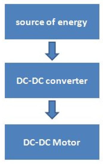
Figure 1.
Traction chain by a direct current motor.
2.1. Photovoltaic Panels
In recent years, photovoltaic panels have garnered increasing interest in power generation for both stationary and onboard applications.
The photovoltaic module is based on a number of cells connected in series and in parallel. This last circuit is based on an ideal current source, which models the photo current Iph, associated in parallel with the diode, which represents the PN junction, to determine the voltage source. Two resistors (Rs and Rp) are added to represent the cell losses [5], as shown in Figure 2.
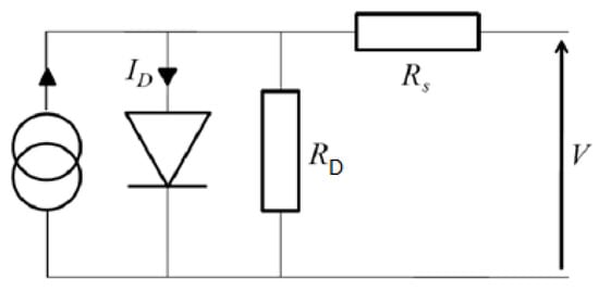
Figure 2.
Photovoltaic panel model.
2.2. Chopper
As mentioned above, photovoltaic panels have garnered increasing interest for their potential in the generation of power for applications such as the electric vehicle. However, some questions are pending, particularly the low voltage produced at the output of the panels. Consequently, a DC/DC converter is essential to raise this voltage to the voltage level of the DC bus. In order to be optimal, DC/DC converters must meet many requirements in electric vehicle applications, namely [6]:
- Low mass and small volume;
- High energy efficiency;
- High power density;
- Low cost;
- Low electromagnetic disturbance; and
- Reduced current ripple to extend fuel cell life.
In addition, the reliability and continuity of service of traction chains is crucial for electric vehicles to access the general public automotive market. Indeed, the presence of faults in the traction chains can lead to malfunctions in the vehicles and thus reducing their performance leveling comparison to conventional vehicles.
In the event that electrical faults do occur, electric vehicle drivelines should include fault-tolerant topologies and/or controls for the DC/DC converter.
This aspect of research focuses on the study of two intertwined DC/DC converter topologies in terms of fault tolerance. The two most critical components in DC/DC converters are aluminum electrolytic capacitors and power switches. Indeed, 60% of malfunctions and breakdowns are due to failures of electrolytic capacitors, while 31% are due to failures of power switches [7].
In [8], Mohamed Kabalo proposes a four-phase floating interleaved boost converter (FIBC). As the same work for [9,10,11], Christopher D. Lute et al. provide an experimental evaluation of a four-phase floating interleaved boost converter for a photovoltaic power system application. However, the principle switches of the proposed converter have a higher voltage stress; therefore, it influences negatively in the output voltage response.
Thus, this study emphasizes the losses of power switches. The electric vehicle uses a photovoltaic panel as the main power source and an auxiliary power source (batteries or super capacitors) to assist the propulsion of the vehicle.
The first topology is an interlaced DC/DC boost converter, known as the interleaved boost converter (IBC), consisting in which connecting connects N boost converters in parallel sharing a common DC bus. The number of phases results from a compromise between the values of the inductors, efficiency, input current ripple, and cost. On the other hand, the second topology is an interlaced floating DC/DC boost converter, commonly called “floating interleaving boost converter”(FIBC) [12]. The latter has certain advantages, for example interlacing and high voltage gain. To respect the equilibrium of the floating bus, the number of interleaves of the FIBC converter must always be even. The choice of the number of phases of this converter results from a compromise between the input current ripple, the volume of inductors, and energy efficiency [13]. The electrical diagrams of the two interlaced topologies are shown on in Figure 3.
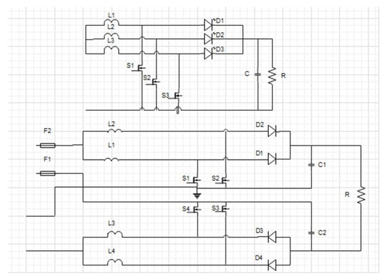
Figure 3.
The two topologies of the interlaced chopper.
2.3. DC Motor
The direct current (DC) motor is a device that has been used in many applications such as electric traction to convert electrical energy into mechanical energy. In most applications, efficiency is very important. For example, if we have a direct current motor in our car, we always try to get the most out of it. Therefore, it is important to study and seek to improve the performance as to continuously maintain the desired performance level [13].
The electrical characteristics of the synthetic winding motor are modeled as an RL series circuit representing the inductance and resistance of the armature. The mechanical part of the motor is modeled as a parallel RC circuit. The electrical and mechanical parts are connected using controlled sources. The rear CEM is also modeled and included in the series with the motor winding so that it opposes the input voltage [14].
2.4. Simulation Results
Figure 4 represents the complete model of the traction chain of the electric vehicle and is composedof a photovoltaic panel, a chopper, and the direct current motor.
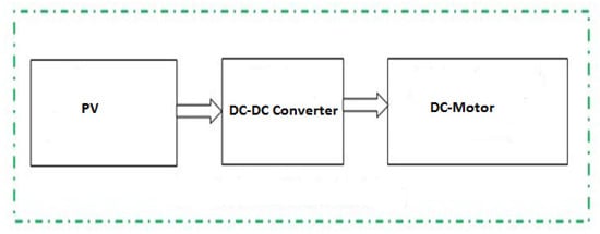
Figure 4.
Traction chain proposed.
The phenomenon of self-heating is characterized by the fact that the production of heat is faster than its dissipation. This then results in a rise in temperature of the system (Figure 5).
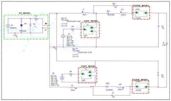
Figure 5.
Simulated traction chain with OorCADcad-PSspice.
However, a sharp rise in temperature can damage or even destroy the electronic component.
The thermal behavior and electrical operation of a component or an electronic system are linked. This connection is due on the one hand to the electrical properties of semiconductors, which are affected by the temperature variation, and on the other hand to the junction temperature which varies depending on the power dissipated and the cooling environment. Thus, in order to increase the reliability of electronic systems and to optimize their thermal design (boxes, operating conditions, location of components on printed circuits, etc.), it is necessary to form a good estimate of the electrothermal behavior of circuits and components. The necessary steps for carrying out the electrothermal coupling of the electronic components are explained in [15].
In the first step we created an electrical model of the electronic component (IGBT, Diode…). Then we defined all the parameters of the electrical model which are affected by temperature (mobility, carrier concentration, lifespan, etc.).
Finally, we developed the thermal model of the entire structure, constituted of the component, its casing, and its cooling to establish communication between these two models [14] (Figure 6).
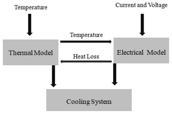
Figure 6.
Electrothermal model of the semiconductor with a cooling system.
In Figure 7 and Figure 8, we illustrate the different output voltages and currents of the chopper in the DC motor.
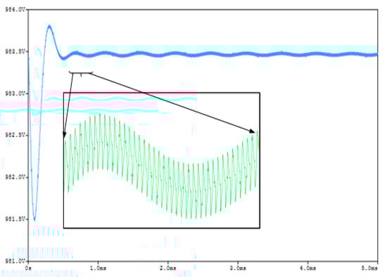
Figure 7.
Chopper output voltage for a temperature of 45 °C.
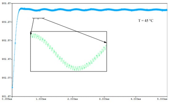
Figure 8.
The chopper output current for T = 45 °C and T = 90 °C.
The output voltage of the chopper for T = 45 °C and T = 90 °C.
The output current of the chopper for T = 45 °C and T = 90 °C.
Figure 7, Figure 8, Figure 9 and Figure 10 represent, respectively, the voltage and the current of the output of the chopper for a temperature of 45 °C and 90 °C.
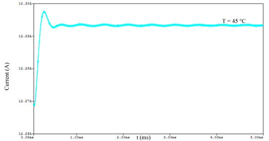
Figure 9.
Chopper output current for a temperature of 45 °C.
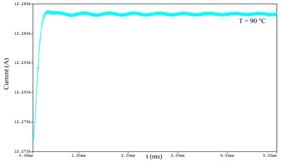
Figure 10.
Chopper output current for a temperature of 90 °C.
As shown in Figure 7, Figure 8, Figure 9 and Figure 10 the ripple of the output voltage of the chopper is very important for the temperature T = 90 °C. This ripple causes adverse effects on the system performance.
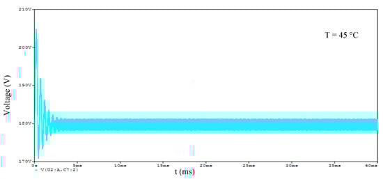
Figure 11.
DC motor voltage for a temperature of 45 °C.
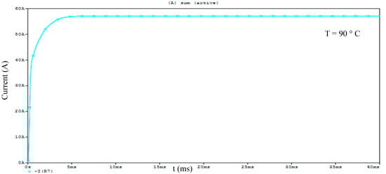
Figure 12.
DC motor current for a temperature of 45 °C.
Vs and Is for T = 90 °C.
Figure 13 shows the motor output voltage and current for a temperature of 90 °C.
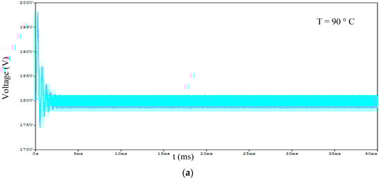
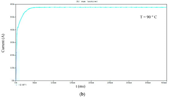
Figure 13.
DC motor voltage (a) and current (b) at 90 °C temperature.
Figure 12 and Figure 13 show the effect of temperature on DC motor voltage and current. It can be concluded that these ripples have adverse effects on the efficiency of the system. This makes the addition of a cooling system for the semiconductors mandatory.
Figure 7, Figure 8, Figure 9, Figure 10, Figure 11 and Figure 12 presented previously show the outputs of the chopper and the outputs of the motor for two temperature values from these curves and we notice that when the temperature increases the ripples become very interesting which influences negatively on system performance.
In the figures below we first show the validation of our model of the interlaced chopper by comparing it to the work published in [16]. The converter efficiency curve as a function of power shows a good compromise between our simulated converters with the semiconductor models developed in [17].
Figure 14 shows the efficiency with and without a semiconductor cooling system. In addition, Figure 15 shows the voltages gain of our interlaced DC/DC converter with and without a cooling system. From these two figures we can see that a semiconductor cooling system would improve the results of the studied system.
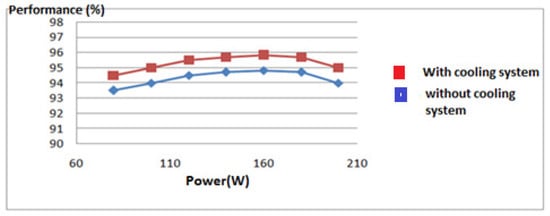
Figure 14.
Efficiency with and without a cooling system.
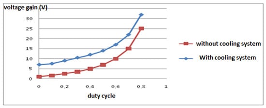
Figure 15.
Voltage gain with and without a cooling system.
3. Electrothermal Modeling of a Traction Chain with an Asynchronous Motor
3.1. UPS with IGBT Module
In this section we develop a simplified electrothermal model of an IGBT module. This model is used to evaluate the thermal parameters in high powers. This model takes into account the thermal influence between the different chips of the module. The latter depends on the boundary conditions, the value of the power dissipated in the different components, and the number of components in operation.
During an operating cycle of a power module in an inverter or chopper, all the chips soldered to the module dissipate heat and also undergo thermal influences between them. The prediction and analysis of thermal behavior during the operating cycles of these modules is important to implementing appropriate solutions that ensure their optimal efficiency, regardless of its environment. Additionally, because the power modules must be mounted on some kind of support or substrate to be usable, the complete system can be formed from several layers of different materials, and the module can be made up of different chips which influence one another [18].
Simulations and numerical experiments represent the primary method to evaluate the thermal impedance curve. The complexity of its structure means that there is a need for a powerful calculation.
3.1.1. Selected Module
The thermal phenomena that we have studied are focused particularly on IGBT modules, which are increasingly used in high and medium power. Depending on the manufacturer and the current rating, these modules comprises either one or more interconnected switches. Our study was carried out on the SKM 75GB 123D (75A/1200V) module from Semikron.
Since the manufacturers do not generally provide the number of chips or their arrangement, we then uncapped the module for the sole purpose of revealing its internal structure. This is shown in Figure 16.
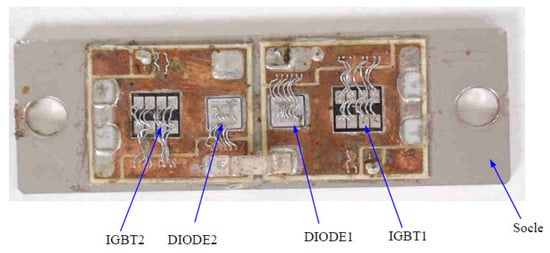
Figure 16.
The interior of the studied IGBT module.
We studied a module in the form of an inverter arm containing two DIODEs and two IGBTs in antiparallel. Each of the components are made up of a silicon chip. The various components module is distributed exactly as shown in Figure 17. The module has a structure [19] containing six essential layers of different materials. Each layer is characterized by its thermal capacity (ρCi), its thermal conductivity (kiet), and its thickness (wi) (Figure 17).
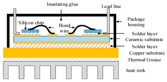
Figure 17.
Geometric description and physical structure of the IGBT module [20].
3.1.2. Model Validation
The thermal model is implemented in the OrCAD-PSpice simulator in order to estimate the junction temperature of IGBT transistors and diodes. The objective of this step is to validate this model for inverter operation.
The diagram in Figure 18 illustrates the variation of the maximum temperature of the junction at the level of IGBT1 as a function of the boundary conditions for different values of dissipated power. These results are obtained by numerical simulations using the developed model. Good agreement between the two types of evolution is observed. We present the variations obtained in the case where the module operates as an inverter (two IGBTs and two DIODEs operate simultaneously).
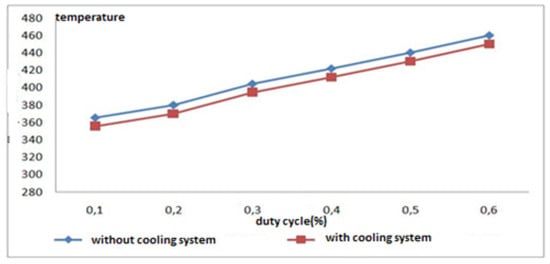
Figure 18.
Evolution of the junction temperature in IGBT.
The equivalent resistance of the radiator is given by the following formula:
Ta is the ambient temperature in K.
Despite the simplicity of the proposed thermal model, it is clear that the latter provides appropriate thermal behavior in the steady state. The technique used to present the thermal influence between the various components allows for an acceptable correction of the junction temperature value. For a low value of thermal resistance of the radiator (0.2 K/W), this correction is equivalent to 16 K (in inverter operation and PIGBT = 110 W; PDIODE = 60 W). This value may be higher as the thermal resistance increases.
For thermal descriptions in multi-chip structures, the thermal interaction between modules has been taken into consideration. First, the thermal behavior of each component of the module operating alone was studied. An analytical method was developed and a simple RC model was adopted to evaluate the resistance and heat capacity in order to estimate the transient thermal impedance of the IGBT and the diode. This method is a quick and useful way to assess the thermal behavior of components.
3.1.3. Asynchronous Motor
Electrothermal modeling and simulation allow the resolution of the electrical problem and the coupled thermal problem. In the case of semiconductors, the electrical model must represent the electrical behavior with physical properties which depend on the temperature. The thermal model ensures the estimation of the temperature in the device as a function of internal heat sources and exchanges with the outside. In this step, we study the effect of temperature on asynchronous motors dedicated to electric traction.
In the previous sections, we have developed electro thermal models of the IGBT and the DIODE based on the electrical equation models and the variation of the temperature-sensitive electrical parameters obtained from the datasheets. These models make it possible to adequately represent the static and dynamic behaviors of the IGBT and of the DIODE and the minimization of the simulation time of complex systems. These models take into account the variations of the static characteristics as a function of the temperature.
Figure 5 describes the principle of the simulation procedure for the electro thermal modeling of a converter based on power modules (IGBT or diode) linked to an asynchronous motor. The power dissipated by the component is injected into our thermal model, to evaluate the junction temperature of the component. The temperature is injected into the electrical model of the component and has electrical parameters depending on this temperature. This calculation is carried out simultaneously using a circuit-type simulator. We present the effect of temperature on the efficiency of the asynchronous motor.
AC machines are now widely used because of the flexibility of their control. This has become possible as a result of the progress made in the field of power electronics converters and their associated controls. In fact, we find the alternation of current machines in practically all fields of variable speed drive. These machines are increasingly replacing direct current machines which are fragile because of the presence of the brush/collector system that limits their field of use [12].
To improve the behavior of the electric model proposed in the library of OrCAD-PSpiceorcad-pspice and to take into account the effect of the junction temperature of the DIODE in the variation of the static characteristic, modifications have been introduced on the classical model. Indeed, the resistance RD in the on state of the diode and the voltage VD will be a function of the junction temperature.
3.2. Simulation Results
3.2.1. Inverter Arm
A thermal model has been developed for a “600V/20A” IGBT chip. We are interested in the temperature of the component. In this step, we focus on an inverter arm with two IGBTs and two diodes on a substrate. The IGBT chips and diodes are from the Mitsubishi Power Semiconductor. Figure 19 illustrates the electrical diagram of the module used.
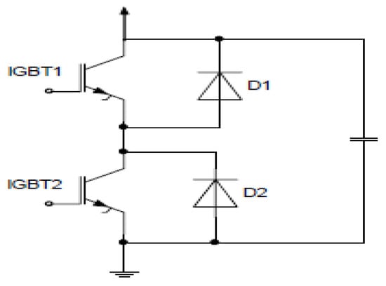
Figure 19.
Electrical diagram of the inverter arm.
The electrothermal validation of the IGBT module (the 600V/50A IGBT chip) was carried out by comparing the measurement of the thermal response, during the cooling phase of the IGBT after a self-heating phase under a short-controlled circuit.
Figure 20 illustrates the switching circuit of an IGBT module.
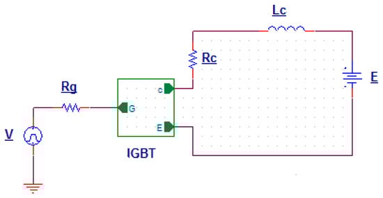
Figure 20.
The switching circuit of an IGBT module.
Figure 21 represent the temperature variation as a function of time with and without a cooling system.
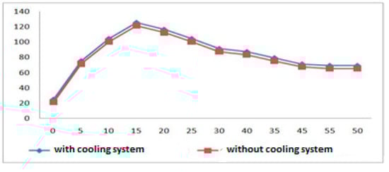
Figure 21.
Temperature variation as a function of time with and without a cooling system.
3.2.2. Results of an Asynchronous Machine Application Inverter
Pulse Width Modulated (PWM) voltage inverter is a static converter of electrical energy that transforms a DC voltage source into an AC voltage supply to power AC loads. The three-phase inverter has six switching cells (IGBT) and six freewheeling diodes. Each arm of the inverter is made up of two switching cells. Each consists of the switch with its diode, with the output corresponding to the midpoint of the arm. The control signals of the switches of each arm must be complementary to avoid short-circuiting the DC power supply to the inverter (Figure 22) [21].
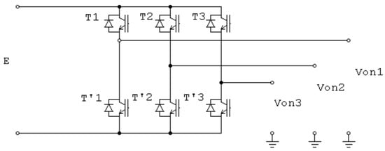
Figure 22.
Chain studied: inverter with an asynchronous machine.
The theoretical notions previously presented were explored to establish a model which simulates the electrothermal behavior of an asynchronous machine supplied by a voltage inverter.
After modeling the power semiconductors and applying these models in the inverter, we proceed to simulate the electric traction system under the OrCAD-PSpice software.
In multi-chip structures, the components under the dissipated power cause the heating of their neighborhood. Our adopted method was used to estimate the thermal influences caused by the different chips of the hybrid structure and to improve the correction due to the thermal interaction between the different chips. A cooling system is added to the developed model of the diode and the IGBT. Simulations giving the variation of the mutual thermal influence of the components according to the limiting conditions of the case and the amplitude of the dissipated power are presented (Figure 23) [22].
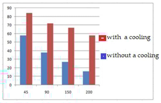
Figure 23.
Efficiency with and without a cooling system.
4. Conclusions
In this article, simplified electrothermal models of two electric traction chains have been developed. This simple and effective representation requires a relatively low calculation time, certainly reducing the simulation time of a complete electrothermal analysis of the module. The support we used for the implementation of this model is the Pspice software, which is an important simulation tool where several types of physical phenomena can be described. The flexibility of this tool encouraged its use as the developed model would be used to study a complete electrothermal model. The user can implement the electrothermal model in any simulation tool with a description language.
The study of power semiconductor components is a discipline in its own right. Our goal in this article is not to deal with details of the physics of semiconductors or their manufacturing technology. We have considered keeping it to the minimum necessary to present the basics of semiconductor physics in a simple way. We have confirmed the simulation results obtained by the electrothermal model by comparing them with the results obtained experimentally. We found a very good correlation between the different thermal responses. In addition, we have added a cooling system for the semiconductors, this system improves the performance of the asynchronous motor and the DC motor.
The comparison shows that these models are simple, tunable with the electric circuit software simulator. They benefit from a better ability to predict the main circuit parameters necessary for power electronics design. The results obtained show that these models have adapted to complete electrothermal simulations of power electronic circuits.
The results obtained are satisfactory and make it possible to open a path to several lines of research with the aim of improving the performance of power electronic systems dedicated to electric vehicles and better improving the electrothermal modeling of these systems.
Author Contributions
Conceptualization, W.H. and M.A.; methodology, W.H.; software, W.H.; validation, W.H., S.M. and M.A.; formal analysis, W.H.; investigation, W.H.; resources, W.H.; data curation, W.H.; writing—original draft preparation, W.H.; writing—review and editing, S.M. and M.A.; visualization, S.M.; supervision, M.A.; project administration, M.A.; funding acquisition, S.M. All authors have read and agreed to the published version of the manuscript.
Funding
This research was funded by the deanship of scientific research of Qassim University.
Data Availability Statement
The study did not report any data.
Acknowledgments
The researcher(s) would like to thank the Deanship of Scientific Research, Qassim University for funding the publication of this project.
Conflicts of Interest
The authors declare no conflict of interest.
References
- Agrawal, M.; Rajapatel, M.S. Global Perspective on Electric Vehicle 2020. Int. J. Eng. Tech. Res. 2020, 9, 1. [Google Scholar]
- Karimi, D.; Behi, H.; Jaguemont, J.; El Baghdadi, M.; Van Mierlo, J.; Hegazy, O. Thermal Concept Design of MOSFET Power Modules in Inverter Subsystems for Electric Vehicles. In Proceedings of the 2019 9th International Conference on Power and Energy Systems ICPES, Perth, Australia, 10–12 December 2019. [Google Scholar]
- Hanini, W.; Ayadi, M. Electro thermal modeling of the power diode using Pspice. Microelectron. Reliab. 2018, 86, 82–91. [Google Scholar] [CrossRef]
- Hanini, W.; Ayadi, M. Electrothermal Modeling of the Insulated Gate Bipolar Transistor (IGBT) Using PSpice: Application to DC–DC Converter. J. Control. Autom. Electr. Syst. 2021, 32, 507–521. [Google Scholar] [CrossRef]
- Guesmi, S.; Ghariani, M.; Ayadi, M.; Neji, R. Complete modeling of photovoltaic module with electrical parameters. J. Autom. Syst. Eng. 2017, 11, 163–172. [Google Scholar]
- Hanini, W.; Rtibi, W. Modeling semiconductors and application to the losses of chopper and inverter type converters. In Proceedings of the 1st International Conference on Innovative Research in Applied Science, Engineering and Technology (IRASET), Meknes, Morocco, 16–19 April 2020. [Google Scholar]
- Xu, F.; Han, T.J.; Jiang, D.; Tolbert, L.M.; Wang, F.; Nagashima, J.; Barlow, F. Development of a SiC JFET-Based Six-Pack Power Module for a Fully Integrated Inverter. IEEE Trans. Electron. 2013, 28, 1464–1478. [Google Scholar] [CrossRef]
- Kabalo, M.; Paire, D.; Blunier, B.; Bouquain, D.; Godoy Simões, M.; Miraoui, A. Experimental evaluation of four-phase floating interleaved boost converter design and control for fuel cell applications. IET Power Electron. 2013, 6, 215–226. [Google Scholar] [CrossRef] [Green Version]
- Kianpour, A.; Shahgholian, G. A floating-output interleaved boost DC–DC converter with high step-up gain. Automatika 2017, 58, 18–26. [Google Scholar] [CrossRef] [Green Version]
- Lute, C.D.; Simões, M.G.; Brandão, D.I.; Al Durra, A.; Muyeen, S.M. Experimental evaluation of an interleaved boost topology optimized for peak power tracking control. In Proceedings of the 40th Annual Conference of the IEEE Industrial Electronics Society, Dallas, TX, USA, 29 October–1 November 2014; pp. 2096–2102. [Google Scholar]
- Lute, C.D.; Simões, M.G.; Brandão, D.I.; Al Durra, A.; Muyeen, S.M. Development of a four phase floating interleaved boost converter for photovoltaic systems. In Proceedings of the 2014 IEEE Energy Conversion Congress and Exposition (ECCE), Pittsburgh, PA, USA, 14–18 September 2014; pp. 1895–1902. [Google Scholar]
- Hanini, W.; Ayadi, M. Comparison of IGBT switching losses modeling based on the datasheet and an experimental study. In Proceedings of the 19th International Conference on Sciences and Techniques of Automatic Control and Computer Engineering (STA), Sousse, Tunisia, 24–26 March 2019. [Google Scholar]
- Bellone, S.; Di Benedetto, L. A Model of the ID—VGS Characteristics of Normally ‘OFF’ 4H-SiC Bipolar JFETs. IEEE Trans. Power Electron. 2014, 29, 514–521. [Google Scholar] [CrossRef]
- Du, B.; Hudgins, J.L.; Santi, E.; Bryant, A.T.; Palmer, P.R.; Mantooth, H.A. Transient thermal analysis of power devices based on Fourier-series thermal model. In Proceedings of the 2008 IEEE Power Electronics Specialists Conference, Rhodes, Greece, 15–19 June 2008. [Google Scholar]
- Hanini, W.; Ayadi, M. Efficiency improving of a static converter using a cooling system for semiconductors. In Proceedings of the International Conference on Recent Advances in Electrical Systems (ICREAS), Hammamet, Tunisia, 22–24 December 2017. [Google Scholar]
- Bouguezzi, S.; Ayadi, M.; Ghariani, M. Developing a simple analytical thermal model for discrete semiconductor in operating condition. Appl. Therm. Eng. 2016, 100, 155–169. [Google Scholar] [CrossRef]
- Su, M.; Zhao, Z.; Zhu, Q.; Dan, H. A converter based on energy injection control for AC-AC, AC-DC, DC-DC, DC-AC conversion. In Proceedings of the 13th IEEE Conference on Industrial Electronics and Applications (ICIEA), Wuhan, China, 31 May–2 June 2018. [Google Scholar]
- Hu, Z.; Zhang, W.; Wu, J. An Improved Electro-Thermal Model to Estimate the Junction Temperature of IGBT Module. Electronics 2019, 8, 1066. [Google Scholar] [CrossRef] [Green Version]
- Noh, J.H.; Song, S.I.; Hur, D.J. Numerical Analysis of the Cooling Performance in a 7.2 kW Integrated Bidirectional OBC/LDC Module. Appl. Sci. 2020, 10, 270. [Google Scholar] [CrossRef] [Green Version]
- Tao, H.; Zhang, G.; Zheng, Z. Onboard charging DC/DC converter of electric vehicle based on synchronous rectification and characteristic analysis. J. Adv. Transp. 2019, 2019, 1–10. [Google Scholar] [CrossRef]
- Tian, H.; Tzelepis, D.; Papadopoulos, P.N. Electric Vehicle charger static and dynamic modelling for power system studies. Energies 2021, 14, 1801. [Google Scholar] [CrossRef]
- Zhu, X.; Kong, L.; Yang, X.; Xu, Y. Design of Vehicle Charger for Pure Electric Vehicle Based on MATLAB Simulation. In Proceedings of the 6th International Forum on Engineering Materials and Manufacturing Technology (IFEMMT), Jilin, China, 17–19 July 2020; Volume 1635, p. 12020. [Google Scholar]
Publisher’s Note: MDPI stays neutral with regard to jurisdictional claims in published maps and institutional affiliations. |
© 2022 by the authors. Licensee MDPI, Basel, Switzerland. This article is an open access article distributed under the terms and conditions of the Creative Commons Attribution (CC BY) license (https://creativecommons.org/licenses/by/4.0/).