
High Gain Converter with Improved Radial Basis Function Network for Fuel Cell Integrated Electric Vehicles

 ,
, 
Abstract
1. Introduction
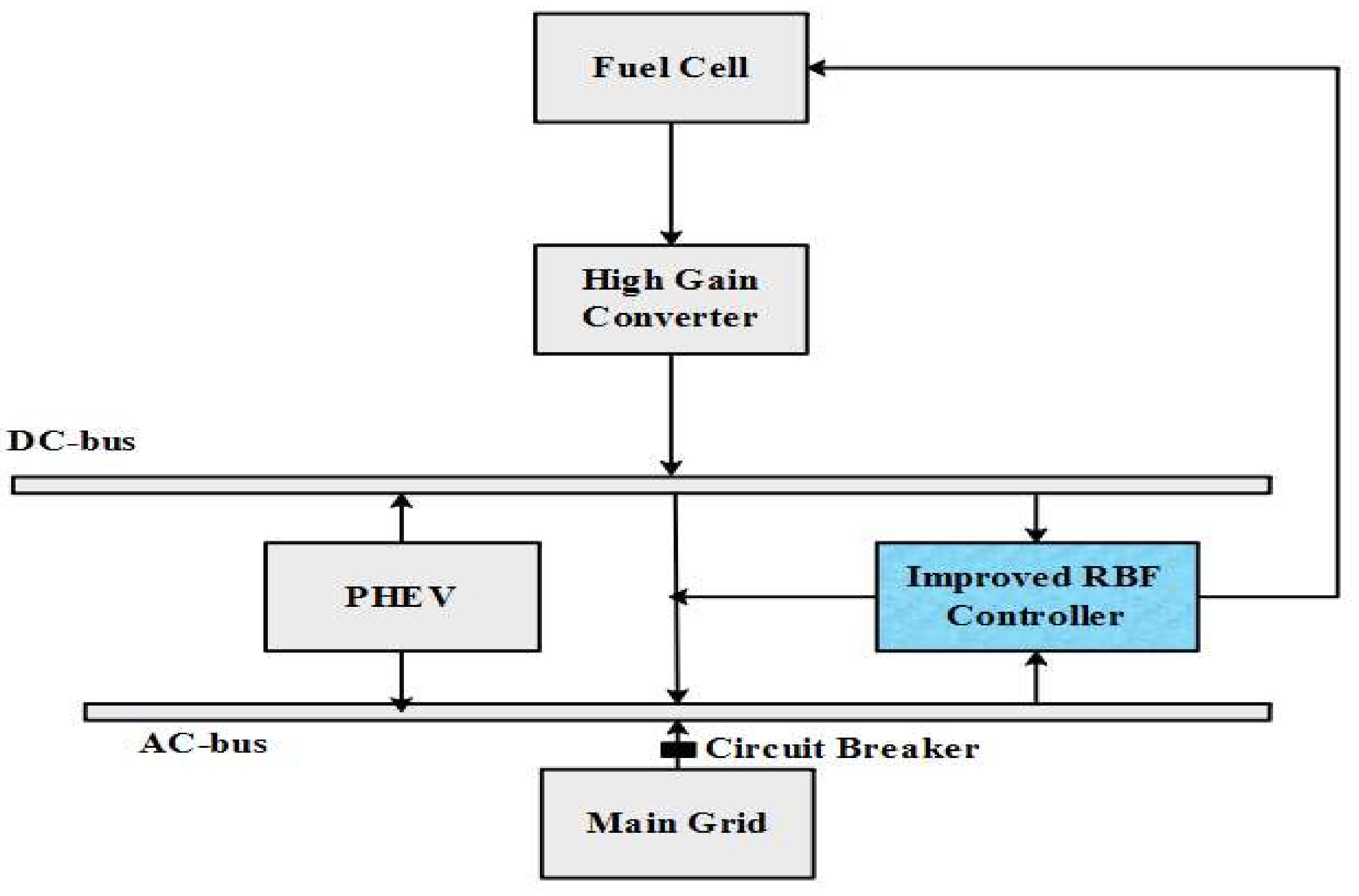
- In this paper, a bidirectional high-gain converter with improved RBF is projected that could incorporate DC at various levels of voltages and similarly control the voltage level to the DC bus and vice versa.
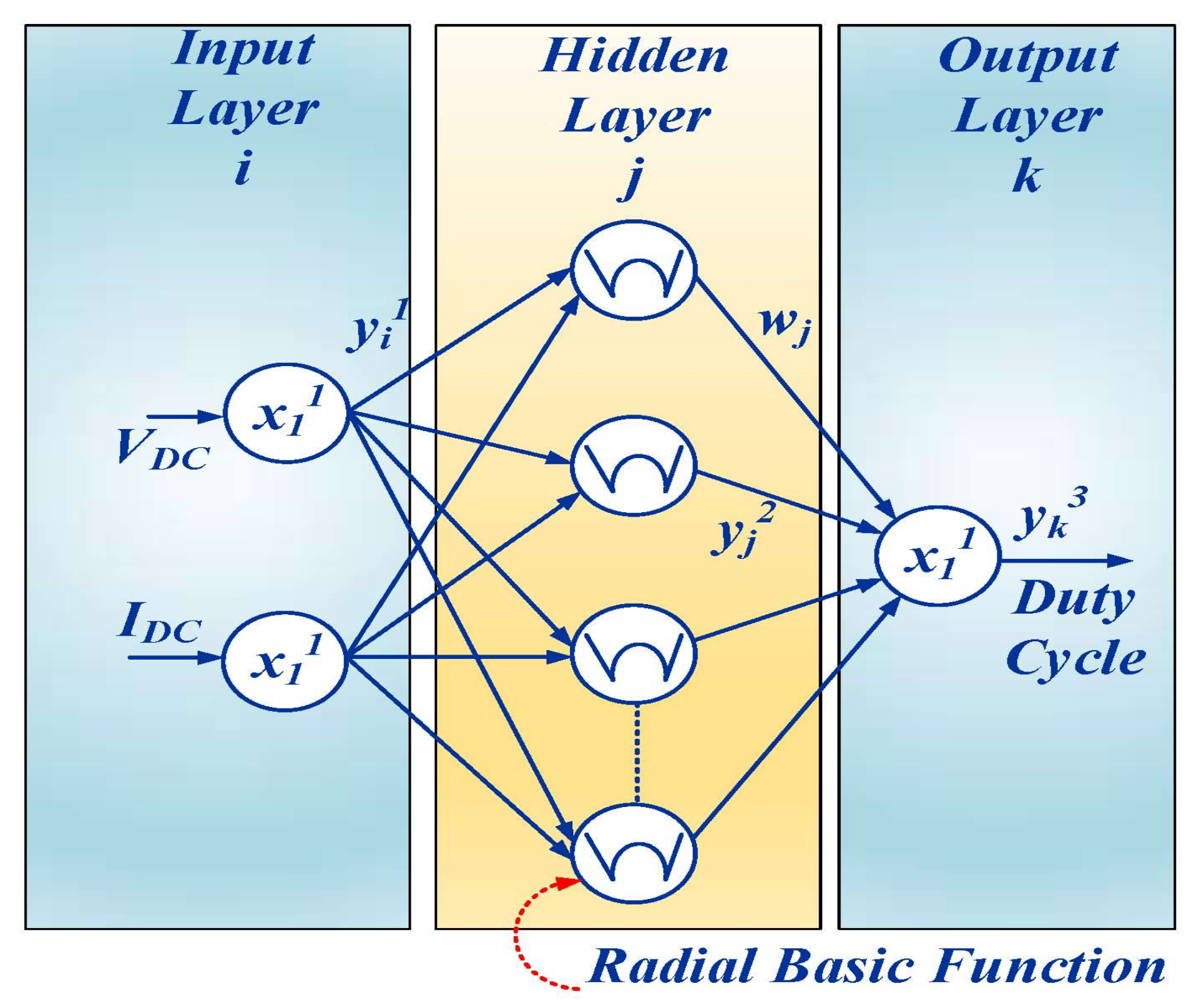
- To control the output voltage of the high-gain converter, an improved RBF controller is designed to change the duty cycle.
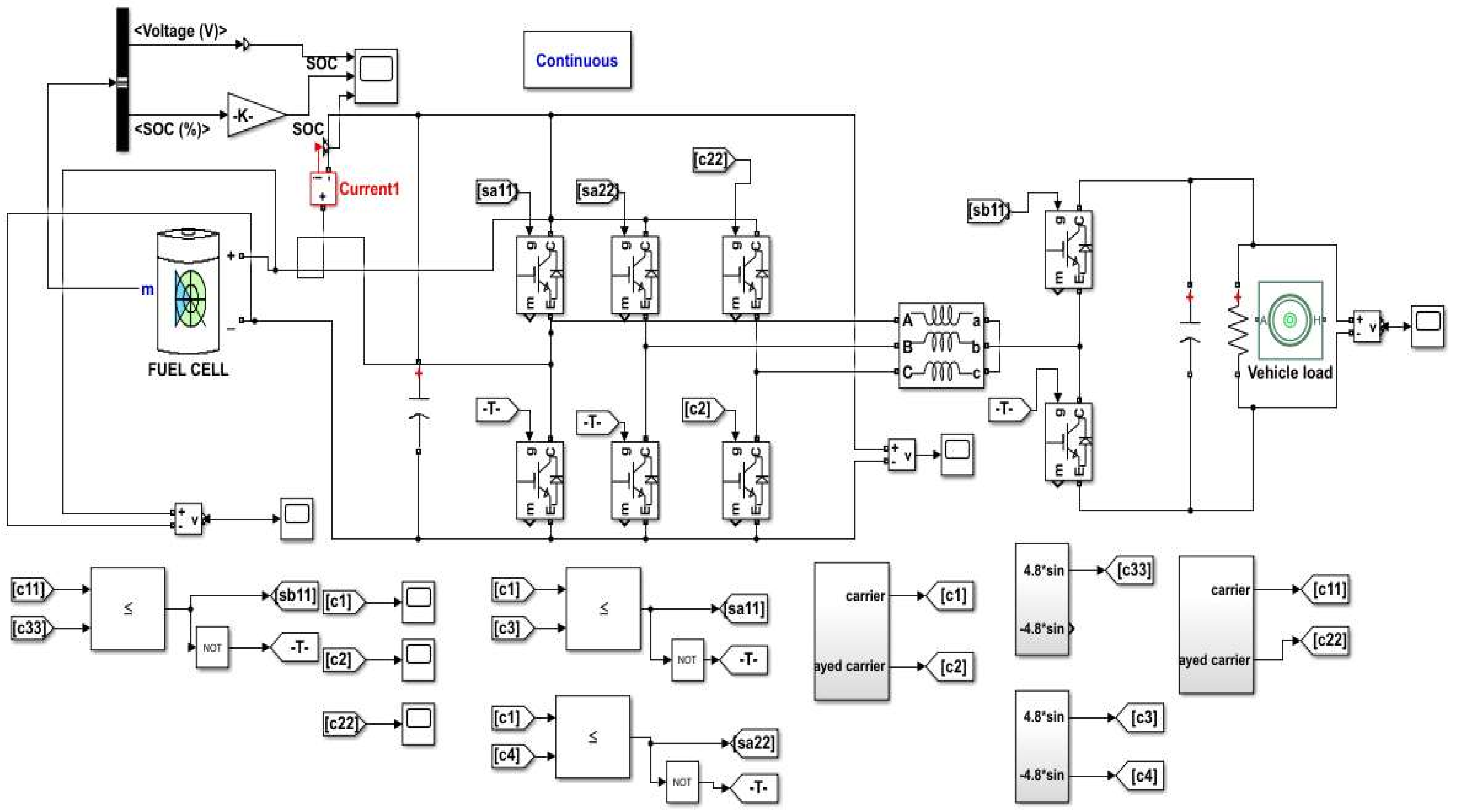
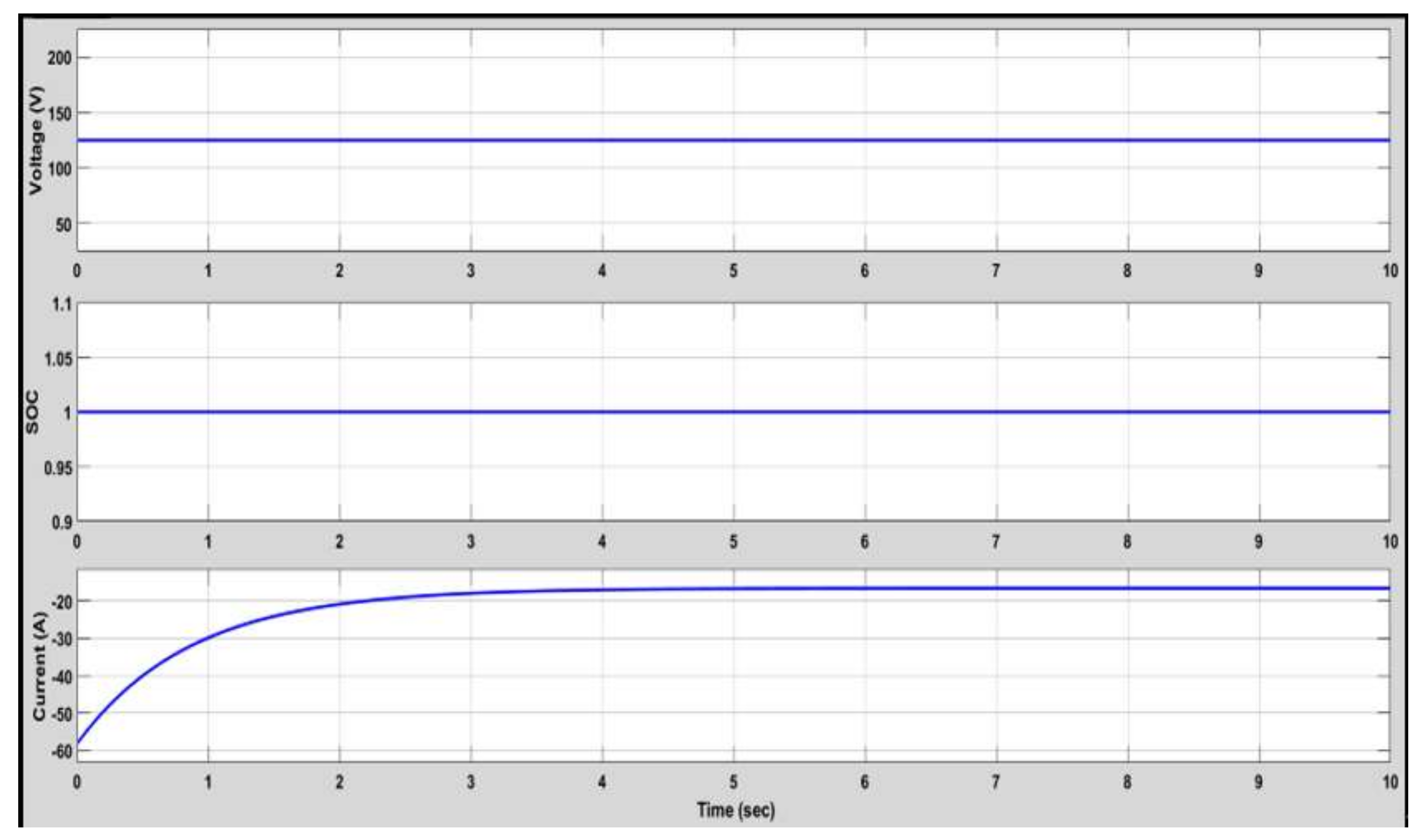
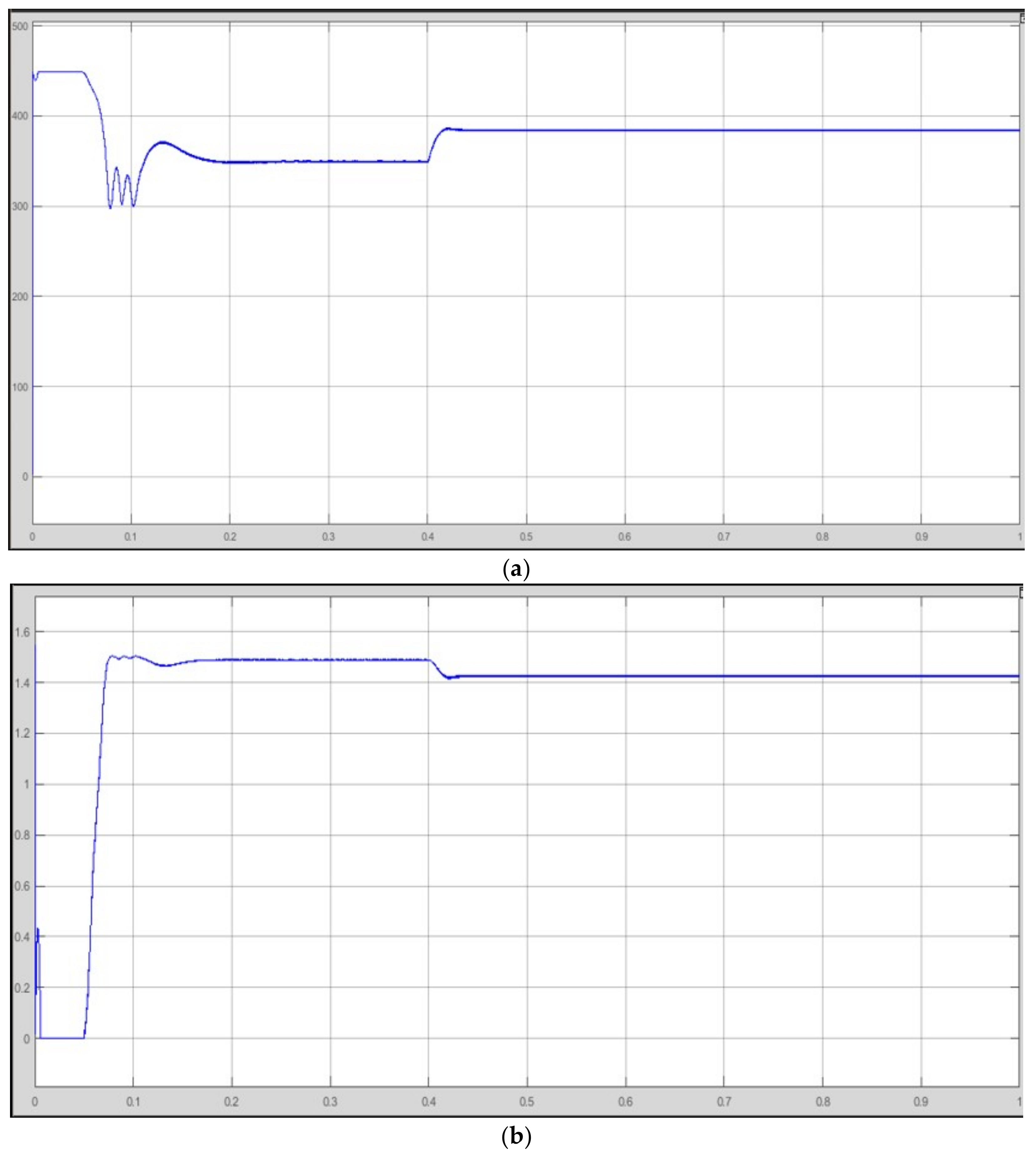
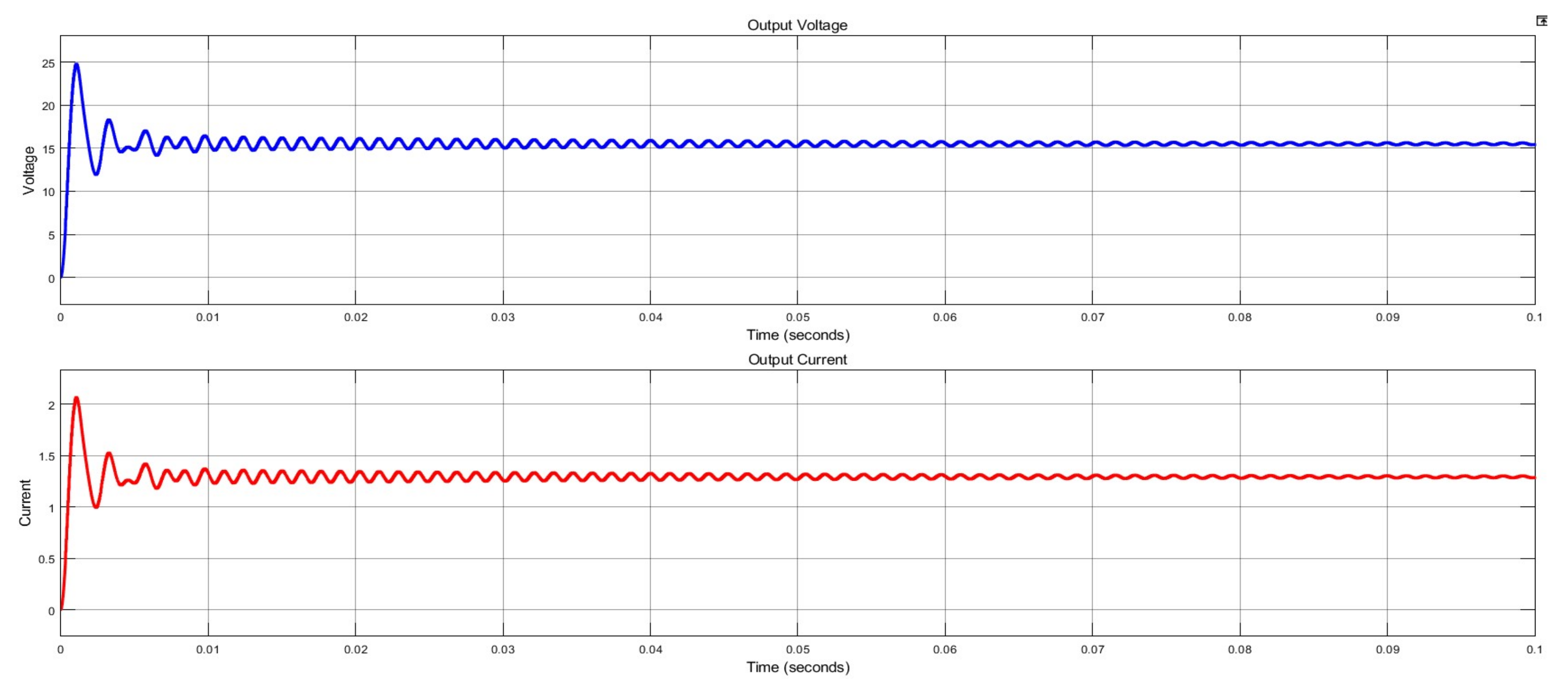
- An improved RBF with HGC is designed using MATLAB/SIMULINK, and its performance parameters of speed, power loss, input/output voltage waveforms, and THD for steady-state operation are analyzed.
2. Literature Review
3. Problem Statement
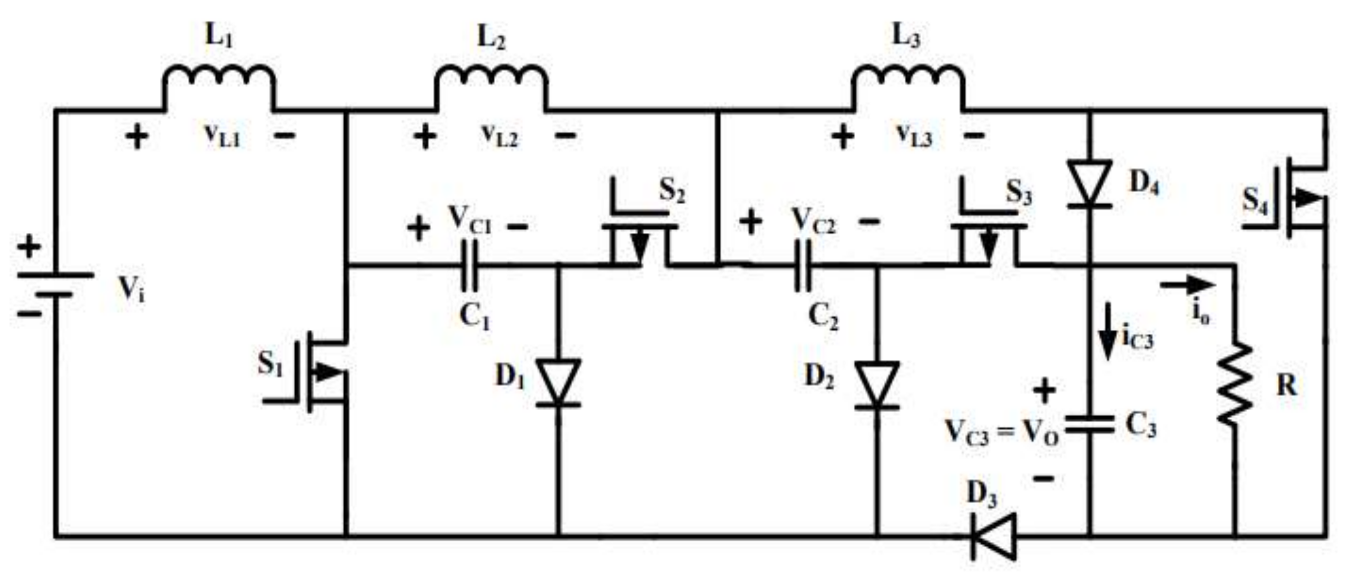
- Converters have a high voltage ratio, which leads to huge losses in electrical components, and voltage stress occurs at converting stages.
- Once the capacitor is exploited, more current transfers through the switches, which creates damage to the circuit. So, the efficiency of the converter can be decreased by this process.
- Furthermore, charging the vehicle battery has more impact on increasing the total harmonic distortion rather than the power losses.
4. Proposed Method
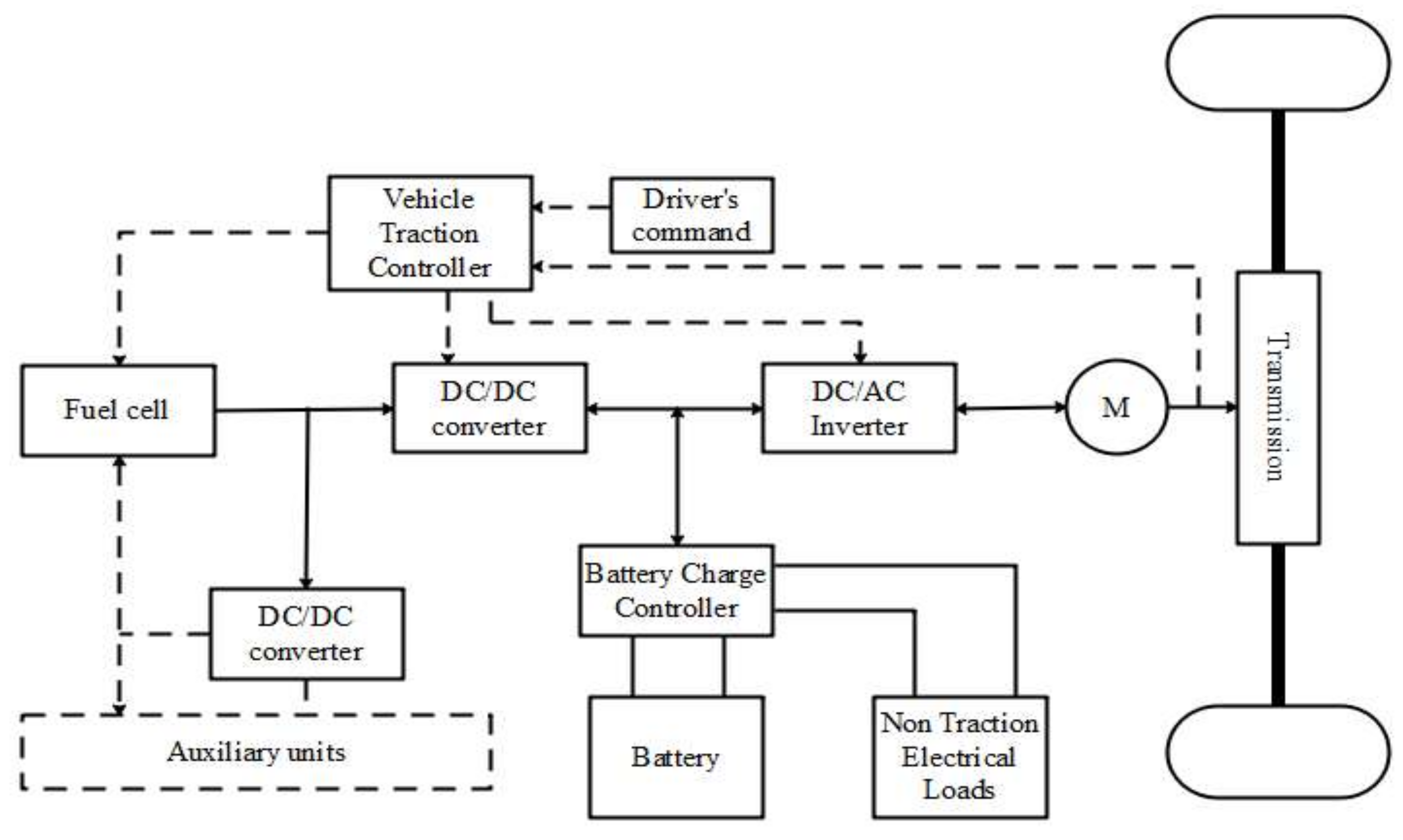
- During vehicle acceleration, the initial energy input from the battery is visible until the fuel cell starts producing energy.
- During braking, the fuel cell operation is shut down and the energy is recovered to the high-voltage battery.
- Larger amounts of energy are utilized from both the battery and the fuel cell sources depending on the vehicle’s acceleration rate.
- The high-voltage battery meets the energy requirements of the on-board systems when the vehicle is stationary.
4.1. High-Gain Converter
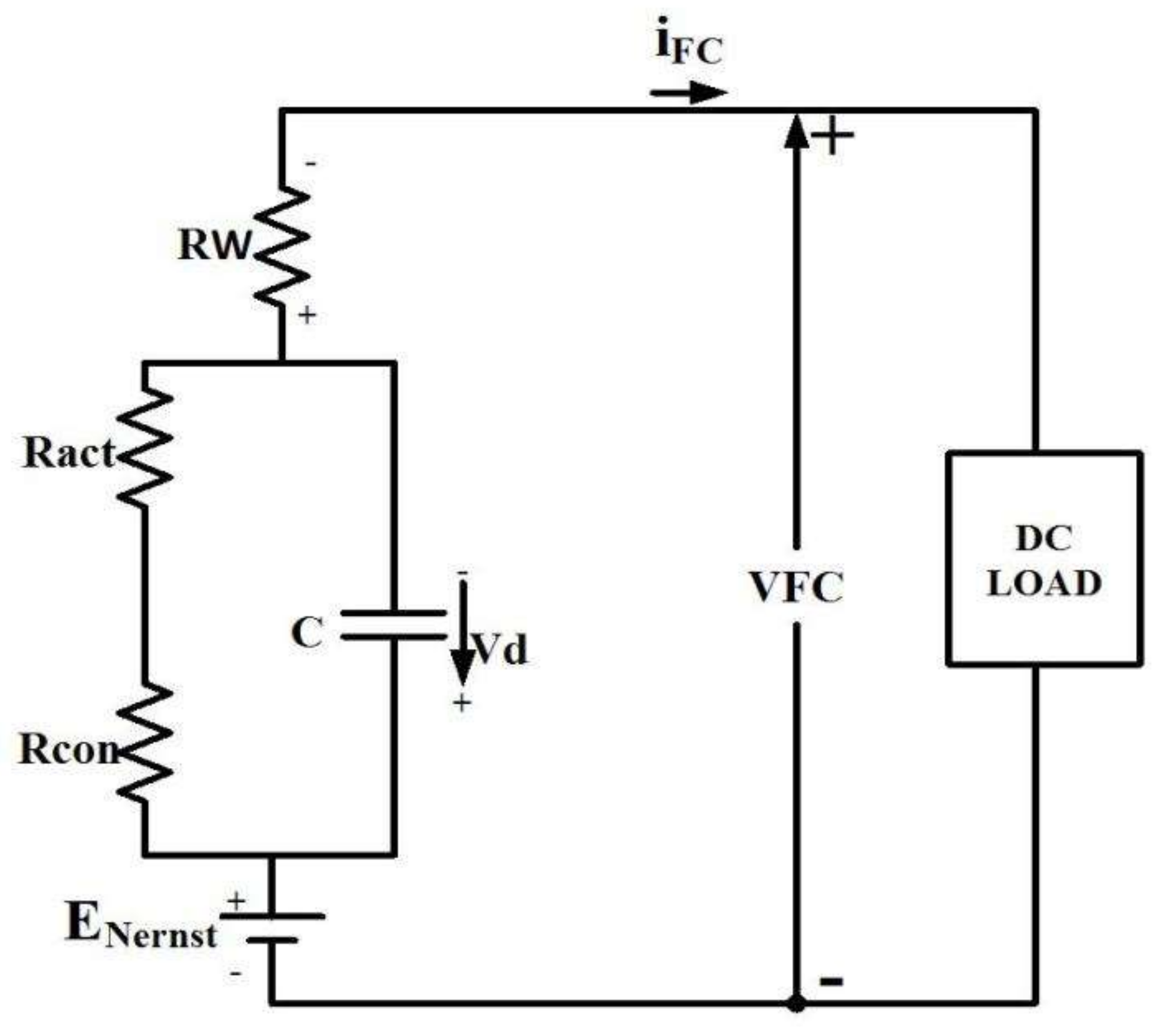
4.2. Modeling of the Fuel Cell
4.3. Backpropagation Algorithm
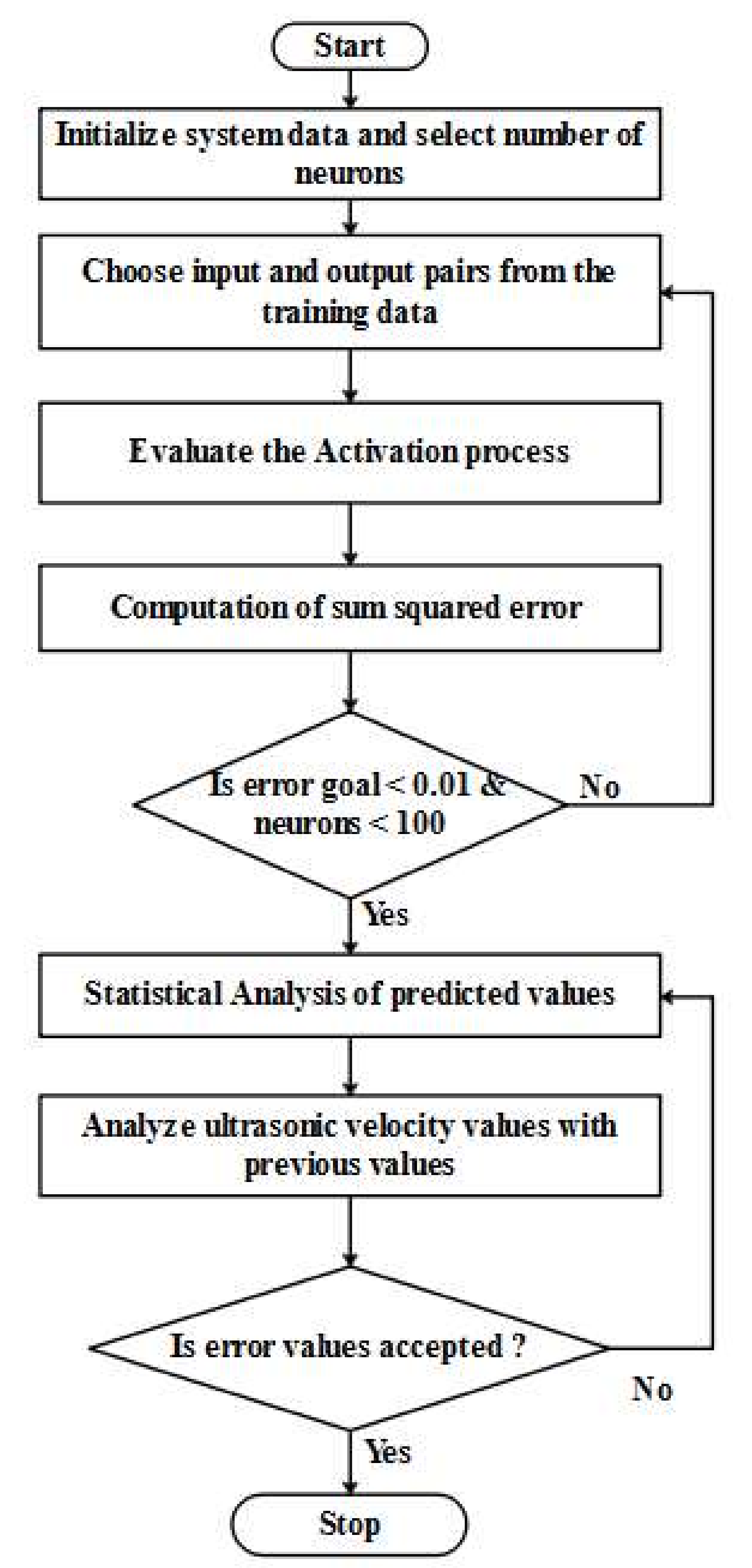
4.4. Radial Basis Function Network Algorithm
Improved RBF Neural Model
5. Results and Discussion
6. Conclusions
Author Contributions
Funding
Conflicts of Interest
References
- Yoo, E.; Kim, M.; Song, H.H. Well-to-wheel analysis of hydrogen fuel-cell electric vehicle in Korea. Int. J. Hydrog. Energy 2018, 43, 19267–19278. [Google Scholar] [CrossRef]
- Han, X.; Li, F.; Zhang, T.; Zhang, T.; Song, K. Economic energy management strategy design and simulation for a dual-stack fuel cell electric vehicle. Int. J. Hydrog. Energy 2017, 42, 11584–11595. [Google Scholar] [CrossRef]
- Thompson, S.T.; James, B.D.; Huya-Kouadio, J.M.; Houchins, C.; DeSantis, D.A.; Ahluwalia, R.; Wilson, A.R.; Kleen, G.; Papageorgopoulos, D. Direct hydrogen fuel cell electric vehicle cost analysis: System and high-volume manufacturing description, validation, and outlook. J. Power Sources 2018, 399, 304–313. [Google Scholar] [CrossRef]
- Eberle, U.; Müller, B.; Helmolt, R.V. Fuel cell electric vehicles and hydrogen infrastructure: Status 2012. Energy Environ. Sci. 2012, 5, 8780–8798. [Google Scholar] [CrossRef]
- Zhou, Y.; Li, H.; Ravey, A.; Péra, M.C. An integrated predictive energy management for light-duty range-extended plug-in fuel cell electric vehicle. J. Power Sources 2020, 451, 227780. [Google Scholar] [CrossRef]
- Wang, H.; Gaillard, A.; Hissel, D. Online electrochemical impedance spectroscopy detection integrated with step-up converter for fuel cell electric vehicle. Int. J. Hydrog. Energy 2019, 44, 1110–1121. [Google Scholar] [CrossRef]
- Nassif, G.G.; de Almeida, S.C. Impact of powertrain hybridization on the performance and costs of a fuel cell electric vehicle. Int. J. Hydrog. Energy 2020, 45, 21722–21737. [Google Scholar] [CrossRef]
- Hong, B.K.; Kim, S.H. Recent advances in fuel cell electric vehicle technologies of Hyundai. ECS Trans. 2018, 86, 3. [Google Scholar] [CrossRef]
- Cipollone, R.; Battista, D.D.; Marchionni, M.; Villante, C. Model based design and optimization of a fuel cell electric vehicle. Energy Procedia 2014, 45, 71–80. [Google Scholar] [CrossRef][Green Version]
- Gaikwad, S.D.; Ghosh, P.C. Sizing of a fuel cell electric vehicle: A pinch analysis-based approach. Int. J. Hydrog. Energy 2020, 45, 8985–8993. [Google Scholar] [CrossRef]
- Lipman, T.E.; Elke, M.; Lidicker, J. Hydrogen fuel cell electric vehicle performance and user-response assessment: Results of an extended driver study. Int. J. Hydrog. Energy 2018, 43, 12442–12454. [Google Scholar] [CrossRef]
- Tanç, B.; Arat, H.T.; Conker, C.; Baltacioğlu, E.; Aydin, K. Energy distribution analyses of an additional traction battery on hydrogen fuel cell hybrid electric vehicle. Int. J. Hydrog. Energy 2020, 45, 26344–26356. [Google Scholar] [CrossRef]
- Lee, D.Y.; Elgowainy, A.; Kotz, A.; Vijayagopal, R.; Marcinkoski, J. Life-cycle implications of hydrogen fuel cell electric vehicle technology for medium-and heavy-duty trucks. J. Power Sources 2018, 393, 217–229. [Google Scholar] [CrossRef]
- Oldenbroek, V.; Verhoef, L.A.; Wijk, A.J.V. Fuel cell electric vehicle as a power plant: Fully renewable integrated transport and energy system design and analysis for smart city areas. Int. J. Hydrog. Energy 2017, 42, 8166–8196. [Google Scholar] [CrossRef]
- Robledo, C.B.; Oldenbroek, V.; Abbruzzese, F.; Wijk, A.J.V. Integrating a hydrogen fuel cell electric vehicle with vehicle-to-grid technology, photovoltaic power and a residential building. Appl. Energy 2018, 215, 615–629. [Google Scholar] [CrossRef]
- Stateczny, A.; Kazimierski, W.; Gronska-Sledz, D.; Motyl, W. The empirical application of automotive 3D radar sensor for target detection for an autonomous surface vehicle’s navigation. Remote Sensing 2019, 11, 1156. [Google Scholar] [CrossRef]
- Stateczny, A.; Burdziakowski, P.; Najdecka, K.; Domagalska-Stateczna, B. Accuracy of trajectory tracking based on nonlinear guidance logic for hydrographic unmanned surface vessels. Sensors 2020, 20, 832. [Google Scholar] [CrossRef]
- Navamani, J.D.; Jegatheesan, R.; Vijayakumar, K. Reliability study of high gain DC-DC converters based on RRPP I-IIA configuration for shipboard power system. Sādhanā 2018, 43, 71. [Google Scholar] [CrossRef]
- Lakshmi, M.; Hemamalini, S. Nonisolated high gain DC–DC converter for DC microgrids. IEEE Trans. Ind. Electron. 2017, 65, 1205–1212. [Google Scholar] [CrossRef]
- Upadhyay, P.; Kumar, R. A high gain cascaded boost converter with reduced voltage stress for PV application. Sol. Energy 2019, 183, 829–841. [Google Scholar] [CrossRef]
- Revathi, B.S.; Mahalingam, P.; Gonzalez-Longatt, F. Interleaved high gain DC-DC converter for integrating solar PV source to DC bus. Sol. Energy 2019, 188, 924–934. [Google Scholar] [CrossRef]
- Amir, A.; Amir, A.; Selvaraj, J.; Rahim, N.A.; Abusorrah, A.M. Conventional and modified MPPT techniques with direct control and dual scaled adaptive step-size. Sol. Energy 2017, 157, 1017–1031. [Google Scholar] [CrossRef]
- Mebarki, N.; Rekioua, T.; Mokrani, Z.; Rekioua, D. Supervisor control for stand-alone photovoltaic/hydrogen/battery bank system to supply energy to an electric vehicle. Int. J. Hydrog. Energy 2015, 40, 13777–13788. [Google Scholar] [CrossRef]
- Fathabadi, H. Novel battery/photovoltaic hybrid power source for plug-in hybrid electric vehicles. Sol. Energy 2018, 159, 243–250. [Google Scholar] [CrossRef]
- Padmagirisan, P.; Sankaranarayanan, V. Powertrain control of a solar photovoltaic-battery powered hybrid electric vehicle. Front. Energy 2019, 13, 296–306. [Google Scholar] [CrossRef]
- Huang, Z.; Zhang, C.; Zeng, T.; Lv, C.; Chan, S.H. Modeling and energy management of a photovoltaic-fuel cell-battery hybrid electric vehicle. Energy Storage 2019, 1, e61. [Google Scholar] [CrossRef]
- Esfandyari, A.; Norton, B.; Conlon, M.; McCormack, S.J. McCormack. Performance of a campus photovoltaic electric vehicle charging station in a temperate climate. Sol. Energy 2019, 177, 762–771. [Google Scholar] [CrossRef]
- Yilmaz, A.S.; Özer, Z. Pitch angle control in wind turbines above the rated wind speed by multi-layer perceptron and radial basis function neural networks. Expert Syst. Appl. 2009, 36, 9767–9775. [Google Scholar] [CrossRef]
- Assareh, E.; Biglari, M. A novel approach to capture the maximum power from variable speed wind turbines using PI controller, RBF neural network and GSA evolutionary algorithm. Renew. Sustain. Energy Rev. 2015, 51, 1023–1037. [Google Scholar] [CrossRef]
- Saravanan, S.; Babu, N.R. RBFN based MPPT algorithm for PV system with high step up converter. Energy Convers. Manag. 2016, 122, 239–251. [Google Scholar] [CrossRef]
- Babu, N.R.; Arulmozhivarman, P. Forecasting of wind speed using artificial neural networks. Int. Rev. Model. Simul. 2012, 5, 2276–2280. [Google Scholar]
- Deng, J.; Li, K.; Irwin, G.W. A two-stage algorithm for automatic construction of rbf neural models. In Proceedings of the MELECON 2010–2010 15th IEEE Mediterranean Electrotechnical Conference, IEEE, Valletta, Malta, 26–28 April 2010; pp. 166–171. [Google Scholar]
- Musavi, F.; Edington, M.; Eberle, W.; Dunford, W.G. Evaluation and efficiency comparison of front end AC-DC plug-in hybrid charger topologies. IEEE Trans. Smart Grid 2012, 3, 413–421. [Google Scholar] [CrossRef]
- Cheng, H.; Wang, Z.; Yang, S.; Huang, J.; Ge, X. An Integrated SRM Powertrain Topology for Plug-In Hybrid Electric Vehicles with Multiple Driving and On-board Charging Capabilities. IEEE Trans. Transp. Electrif. 2020, 6, 578–591. [Google Scholar] [CrossRef]


| Description | Parameter (Value) |
|---|---|
| General vehicle description | Four-seat lightweight niche vehicle |
| Kerb (gross vehicle) weight | 750 kg |
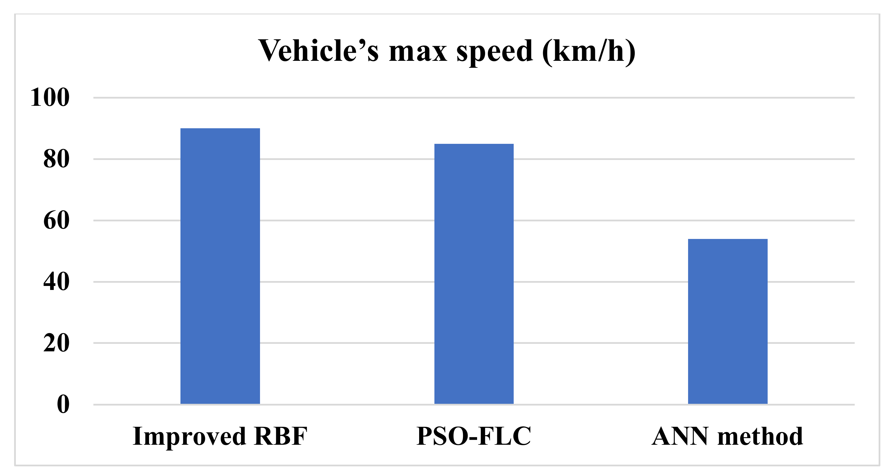
| Top speed | under 90 km/h (55 mph) |
| Propulsion (powertrain) | a plug-in series hybrid FC (FCPHEV) |
| Fuel cell | 3 kW (continuous) air-cooled; Horizon open cathode H-3000 |
| Hydrogen tank | Pressure = 350 bar; capacity = 74 L (holding the capacity of 1.8 kg hydrogen) |
| Battery | 72 V 4.3 kWh LiFePO4 |
| DC motors | 12.5 kW front-wheel drive (Lynch LEM-200/d127) |
| Power converter type | DC/DC converter |
| Total no. of motors | 2 |
| Combined peak power of motors | 40 kW |
| Fuel cell weight and associated systems | Approx. 60 kg |
| Range (fully charged battery and full tank) | Up to 290 km (180 miles) |
| Re-fueling time | 3 min |
| Dimensions | Length = 3.5 m, height = 1.7 m, width = 1.6 m |
| Chassis | Lotus bounded aluminum |
| Transmission type | Belt drive to front wheels |
| Parameters | Ratings |
|---|---|
| Battery voltage | ±200 A up to 200 kW |
| Charging current | Max.10% |
| Current ripple | 7 |
| EMC, cable | IEC 1000-2-4 |
| Rated power | 75 KVA |
| Parameters | Proposed High-Gain Converter |
|---|---|
| EMI issues | Low |
| Dynamic performance | Very good |
| Stability | Very good |
| Output ripple | Low |
| Voltage stress | Low |
| Total number of components | 10 |
| Converter Topology | THD% | Efficiency% | Power Loss (KW) |
|---|---|---|---|
| Existing DC-DC converter | 3.37 | 97.262 | 0.059 |
| Proposed high-gain converter | 3.12 | 98.272 | 0.042 |
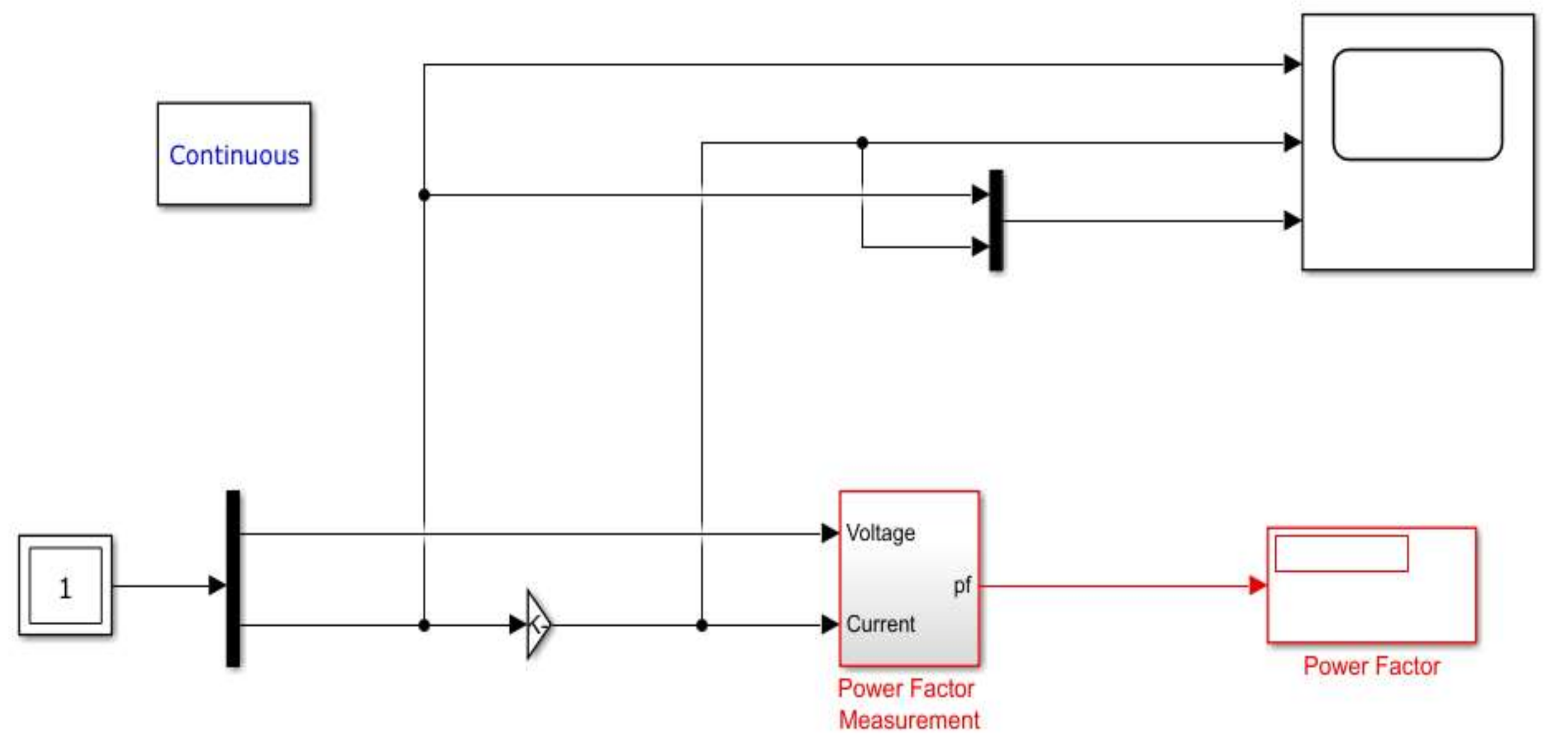
| Converter Topology | PFC |
|---|---|
| Proposed high-gain converter | 0.9946 |
| Existing DC-DC converter | 0.9839 |
Publisher’s Note: MDPI stays neutral with regard to jurisdictional claims in published maps and institutional affiliations. |
© 2022 by the authors. Licensee MDPI, Basel, Switzerland. This article is an open access article distributed under the terms and conditions of the Creative Commons Attribution (CC BY) license (https://creativecommons.org/licenses/by/4.0/).
Share and Cite
Girirajan, B.; Shekhar, H.; Lai, W.-C.; Jagannathan, H.K.; Bidare Divakarachar, P. High Gain Converter with Improved Radial Basis Function Network for Fuel Cell Integrated Electric Vehicles. World Electr. Veh. J. 2022, 13, 31. https://doi.org/10.3390/wevj13020031
Girirajan B, Shekhar H, Lai W-C, Jagannathan HK, Bidare Divakarachar P. High Gain Converter with Improved Radial Basis Function Network for Fuel Cell Integrated Electric Vehicles. World Electric Vehicle Journal. 2022; 13(2):31. https://doi.org/10.3390/wevj13020031
Chicago/Turabian StyleGirirajan, Balasubramanian, Himanshu Shekhar, Wen-Cheng Lai, Hariraj Kumar Jagannathan, and Parameshachari Bidare Divakarachar. 2022. "High Gain Converter with Improved Radial Basis Function Network for Fuel Cell Integrated Electric Vehicles" World Electric Vehicle Journal 13, no. 2: 31. https://doi.org/10.3390/wevj13020031
APA StyleGirirajan, B., Shekhar, H., Lai, W.-C., Jagannathan, H. K., & Bidare Divakarachar, P. (2022). High Gain Converter with Improved Radial Basis Function Network for Fuel Cell Integrated Electric Vehicles. World Electric Vehicle Journal, 13(2), 31. https://doi.org/10.3390/wevj13020031