Article

Bidirectional Converter for Plug-In Hybrid Electric Vehicle On-Board Battery Chargers with Hybrid Technique

by
Gopinath Anjinappa
1,
Divakar Bangalore Prabhakar
1 and
Wen-Cheng Lai
2,3,*
1
Department of Electrical and Electronics Engineering, REVA Institute of Technology and Management, Bengaluru 560064, India
2
Bachelor Program in Industrial Projects, National Yunlin University of Science and Technology, Douliu 640301, Taiwan
3
Department of Electronic Engineering, National Yunlin University of Science and Technology, Douliu 640301, Taiwan
*
Author to whom correspondence should be addressed.
World Electr. Veh. J. 2022, 13(11), 196; https://doi.org/10.3390/wevj13110196
Submission received: 27 June 2022 / Revised: 25 July 2022 / Accepted: 30 July 2022 / Published: 22 October 2022

Abstract

:
Recently, Plug-in Hybrid Electric Vehicles (PHEVs) have gathered a lot of attention by integrating an electric motor with an Internal Combustion Engine (ICE) to minimize fuel consumption and greenhouse gas emissions. The On-Board Chargers (OBCs) are selected in this research because they are limited by dimensions and mass, and also consume low amounts of power. The Equivalent Series Resistance (ESR) of a filter capacitor is minor, so the zero produced by the ESR is positioned at a high frequency. In this state, the system magnitude gradually drops, causing a ripple in the circuit that generates a harmful impact on the battery’s stability. To improve the stability of the system, a Neural Network with an Improved Particle Swarm Optimization (NN–IPSO) control algorithm was developed. This study establishes an isolated converter topology for PHEVs to preserve battery-charging functions through a lesser number of power electronic devices over the existing topology. This isolated converter topology is controlled by NN–IPSO for the PHEV, which interfaces with the battery. The simulation results were validated in MATLAB, indicating that the proposed NN–IPSO-based isolated converter topology minimizes the Total Harmonic Distortion (THD) to 3.69% and the power losses to 0.047 KW, and increases the efficiency to 99.823%, which is much better than that of the existing Switched Reluctance Motor (SRM) power train topology.

1. Introduction

In recent times, Plug-in Hybrid Electric Vehicles (PHEVs) have been described as the essential component to maintain electric flexibility in microgrids and to combat energy apprehensions [1,2]. Due to their smaller batteries, PHEVs are frequently inexpensive compared to Battery-powered Electric Vehicles (BEVs). Furthermore, regenerative braking in PHEVs could prolong the range of batteries, as is required. Thus, while considering a global view, dissimilar selections of PHEVs could be preferred, deliberated, and distinguished by their Energy Storage Systems (ESSs) [3]. The ultimate idea for PHEVs is to utilize their batteries as the energy storage system to increase the capability of the ESS and maintain a proper charging period [4,5]. The significance of PHEVs has been considered and assessed in terms of power semiconductor devices and their procedures for the grid side [6]. Therefore, the individual charger type is designed and established for training individual prototypes to complete the charging process within 30 min [7]. On the other hand, the OBC type is essentially required to charge appropriately using the local service exit. Subsequently, the PHEV-related batteries are stimulated by the smart grid, which acts as an important aspect for promising the stability of the grid [8]. To date, a lot of research has been carried out in the area of Alternating Current (AC) microgrid control. Additionally, local storage and batteries for electric vehicles are based on Direct Current (DC), which is easily formed [9]. Although it is difficult to construct DC systems with rising capacities and voltage levels [10], DC microgrids are an interesting development for the power industry, since they provide excellent controllability and fewer integration issues for AC power systems. As a result of the above explanations, the concept of hybrid DC–AC microgrids has recently drawn the attention of numerous researchers [11], because numerous advantages are provided by encompassing AC and DC structures with new technologies [12,13].
In recent times, on-board battery-type chargers have been employed in the industry, because stocking vehicles have failed to eliminate the overburden and overcapacity [14]. However, they show a composite battery charging system that combines an OBC with a Low-voltage DC–DC Converter (LDC) for an Electric Vehicle (EV) charger that is tiny and lightweight. Three H-bridge converters—including selective switching, a high-frequency power converter, and inductors—are used in the presented charger [15]. High-Frequency Transformers (HFTs) are an important component of inverter circuits that convert intermittent energy into usable electricity. HFTs are utilized in switching power supplies because they can handle high currents. Consequently, numerous researchers have investigated charging procedures using an inverter for impulsion motor-powered vehicles [16]. EVs are rapidly advancing, opening up substantial prospects to increase the use of sustainable energy in the automotive sector. OBCs are frequently utilized in EVs due to their easy installation and low price [17]. An OBC needs to be power-dense and extremely efficient because of their constrained interior area and quick charging times. A further factor driving interest in bidirectional power flow technologies in the automobile industry is the potential for EVs to provide electricity back into the grid [18]. This article provides a thorough analysis and investigation of the most recent bidirectional OBC methods. OBCs enable EVs to be charged instantly from the utility grid, and are popular in the automobile industry for their practicality—particularly when contrasted with the numerous expensive off-board charging options [19]. Due to their low battery deterioration and straightforward hardware requirements, unidirectional OBCs are widely used. However, the advancement of EVs has made their promise as a portable energy source more apparent [20]. The major aims of this research are as follows:
  • A novel technique called NN–IPSO is proposed to determine the best suitable converter topology for battery charger management.
  • The stability of the system is improved using NN–IPSO, which interfaces the battery with an isolated converter topology.
The organization of the remainder of this paper is as follows: The literature review of conventional methods is presented in Section 2. The proposed approach is explained in Section 3, while the outcomes, discussion, and comparative results of the data are described in Section 4. The conclusions and future perspectives of this research are presented in Section 5.

2. Literature Review

For On-board Battery Charger (OBC) applications, Ramos et al. [21] proposed a control scheme to smooth the power ripple of a single-stage isolated converter for EVs. To regulate the power flow and phase-shift control, the recommended converter employs the interleaving approach and the Dual Active Bridge (DAB) operation. Furthermore, without adding any extra components to the secondary side, this paper provides a control strategy for reducing low-frequency power ripples in topology while maintaining overall size and weight. However, this method does not focus on efficiency and power density measurements.
Mohamed Elshaer et al. [22] developed a unique DC–DC architecture that allows a PHEV to use a power distribution system to recharge its high-voltage batteries. A single rectifier and tertiary complementing capacitance were shared across the two modules by connecting the inductive charging system’s transmitter coil to the rechargeable vehicle’s on-board reversible semiconducting charger. The total area and complexity of the on-board circuitry were reduced because of constituent cooperation between the two modules. The transistor, supplemental valve, and controller led to high costs, but extended the converter’s lifespan. The battery charging condition remained the same; however, a concentrated voltage was intolerable for operating the battery.
A novel combined OBC converter with the vehicle and auxiliary battery charging features was recommended by Nam et al. [23]. A bidirectional full-bridge converter including an operational clamp circuit and a composite LDC converter along with a Phase-Shift Full-Bridge (PSFB) converter and a forward converter made up a conceptual incorporated OBC converter. Extra circuitry consisting of a resistor and a rectifier was used on the tertiary side of the square LDC converter to control the voltage fluctuation between bridge rectifiers and remove the harmonic currents. However, this topology has a higher component count, and some configurations need more than one isolated DC supply.
Denys Zinchenko et al. [24] suggested a single-stage isolated on-board electric car charger with no intermediate DC link. In this research, the designed converter was placed on an independent current source design with gentle shifting in transistors for an AC line operating voltage. The adapter was differentiated by its efficiency qualities, with the continuous power recharging mode achieving the highest efficiency. The proposed design eliminates diode repossession properties in synchronous converter topologies to improve efficiency, but this converter design requires an additional filter that produces less transient response and high output ripples.
An effective two-stage charger design with an upgraded PFC rectifier as the front end and a high-frequency Zero Voltage Switching (ZVS) was proposed by G. Kanimozhi et al. [25]. The second component is a DC–DC converter with current switching (ZCS). For the regulation of PFC and DC voltage, the Resettable Integrator (RI) control approach was used. With a quicker dynamic response and input noise rejection, the regulator was able to manage a nonlinear switching converter while also strengthening its resilience. Resonant circuitry was used in the second stage to help the inverter switches and rectifier diodes achieve ZVS/ZCS. However, taking into account the diode latency, the switching loss increases relative to the power that is shielded from the presence of the diode.
He Cheng et al. [26] proposed a comprehensive Switched Reluctance Motor (SRM) powertrain topology for PHEVs based on a variety of driving and recharging capabilities. Four basic functions were provided in motor driving mode to successfully analyze the driving and braking procedures. Three charging modes were available for battery charging without the use of additional battery chargers. The SRM windings and associated converter circuit were used to create a three-channel intermittent boost converter with power factor adjustment capacity for charging the traction battery. To recharge the extra batteries from the motor or propulsion battery, an incorporated half-bridge impedance DC–DC converter was used, resulting in a higher loss.

Summary

According to the literature mentioned above, the DC–DC converter is the essential component of the PHEV OBC. Currently, DC–DC converters have issues with the lagging leg’s commutation, voltage fluctuations on the transformer’s secondary side, low efficiency, and higher distortion. The higher output voltage of DC–DC converters causes the switching frequency to be significantly wider than the resonance frequency, which naturally increases the power losses. Therefore, the NN–IPSO method, which is utilized to maintain converter operations and stability while using electronic components that consume less power, is presented as a solution to the aforementioned issues.

3. Proposed Method

In the subject of PHEV charging, Neural Networks (NNs) have been frequently used. Traditionally, the classic backpropagation method is used to train Neural Networks. Since this method has some limitations, our NN was trained using Improved Particle Swarm Optimization (IPSO). IPSO is a popular tool for solving a wide range of optimization issues. In contrast to structure, this paper provides a method of control called NN–IPSO for decreasing low-frequency power fluctuations, which are transported to the secondary winding without the use of any external devices. Meanwhile, the converter exchanges the entire power through the series capacitor, so a capacitor with extraordinary capacitance and current management ability is essential. The ability to reduce ripple at the output, reduce switching power losses, enhance power conversion efficiency, and enhance transient and steady-state response are the key benefits of this approach. This research provides an isolated converter that is controlled by NN–IPSO, and proposes using NN–IPSO to control the switching of a bidirectional AC–DC converter. An AC–DC converter using this neural network application includes advantages such as faster switching responsiveness, simpler construction, and a better output waveform. A PWM rectifier switching states or a predictive state observer and controller, such as one based on artificial intelligence, can be used to modify the converter to eliminate switching losses that cause transient circumstances.

3.1. Setup of the Bidirectional Converter

This research describes the isolated portion of the energy supply, and its controller technique depends on switch effectiveness and voltage quantities, which are established cooperatively to accomplish the regulation at the input side. The following elements are included in the suggested design:
  • Integration of the traction inverter with the charging system.
  • Integration of the charging system detector with the motor winding inductance, considerably decreasing the system’s mass. Furthermore, it has little effect on the rotor-side converter or the operation of common EV motors.
  • The capacity to block faults in both directions.
  • The ability to recharge at lower or higher voltages than the voltage supply.
  • The circuit illustration of the isolated converter is displayed in Figure 1.
The functionality of the driving and charging conditions for Figure 1 is demonstrated in [27]. DC power input is represented as a current source that does not supply any power at first. To ensure switching stability, a 4800 F is placed in parallel to the power source, and the monitoring system maintains 230 V across its connections to avoid energy absorption and assure full transmission. The bidirectional converter is made up of three basic phases: DC–AC–DC, DC–AC–DC, and DC–AC–DC. With the use of the intermediate AC stage, a motor winding is used to raise the input voltage to the velocity profiles. The HFT is in charge of creating voltage support, which results in a large modulation index [28]. This configuration links a half-bridge to the motor’s neutral point, with the negative terminal connecting to the anode of the battery. As explained previously, this method only needs a neutral point connection to the motor that can be used with neither synchronous or induction motors. Semi-conductive elements and their associated driver systems are the only additions to a normal EV drivetrain. As a consequence, the incremental weight is almost non-existent. The operations of the converter are described as follows:
  • Whenever the signal is high, the switches S1 and S2 are continuously activated; whenever the voltage is low, the switches S1, and S2 are switched off.
  • This switching method allows the propagation of the antiparallel transistors of the switching devices relating to phase.
  • Similarly, whenever the signal is high, switches S3 and S4 should be engaged; whenever the voltage is low, switches S3 and S4 should be shifted to off; switches S5 and S6 should always be triggered whenever the signal is high; and switches S5 and S6 should always be switched off if the voltage is low.
  • The remaining switches have a 50% duty cycle and a constant current. Only when the topmost bidirectional switch of a half-bridge is fully triggered (with j = 1, 3, or 5), and the voltage of the cycle linked is optimistic, is the voltage level at the winding also optimistic.
  • When the bottom switch (with k = 2, 4, or 6) is fully triggered under identical conditions, the voltage is zero. If the phase voltage is low, the direction of the voltage is the aspect of the voltage in the previous circumstances.
  • Whenever the topmost switch on every limb of the converter is active, the signal applied to the respective winding is also high, and whenever the bottom switch is triggered, it is negligible. If another minimum or maximum switch is turned on at the same time, the voltage supplied to the associated windings is zero. The PHEV uses a battery with a voltage range of 200 V–400 V.

3.2. Block Diagram of the Proposed Method

The block diagram of the on-board charging process is shown in Figure 2. This block consists of a battery, load, converter, motor windings, and the NN–IPSO controller. Initially, the power from the battery charger is used as an input, which is employed for the conversion process; then, the motor winding is placed in between the source and the load to transfer the power. After crossing the motor winding, a DC–DC converter is held to convert the variable DC to fixed DC with the help of the proposed NN–IPSO controller.

3.3. NN Process

Neural Networks are capable of learning on their own and producing output that is not dependent on the input given to them. Instead of being stored in a database, the input is kept in its own networks. As a result, data loss has no impact on how it functions. This research paper deals with the reduction in THD in an isolated converter topology with an Artificial Neural Network technique. This topology consists of inferior blocking voltage differences, and needs a lesser number of power switches and DC voltage sources, resulting in reduced complexity and price for the entire system. The NN was constructed via the backpropagation procedure of the Mean Square Error (MSE) of the preferred rates, and utilized to model composite associations between inputs and outputs, or to discover data designs. The training dataset was created offline by resolving these nonlinear equivalences using the Newton–Raphson technique. To execute this procedure, MATLAB design software was exploited, because its implementation is easier and faster [29]. The set of input ranges was accessible in the NN process, and step-by-step designs were created in the forwarding track to determine the output design. MSE-produced patterns are minimalized by the gradient descent technique, which changes the loads at the time of initiating the output layer. Once the training phase is concluded, the accomplished NN is exploited to produce the control structure of the isolated converter, and correspondingly utilized for the production of ideal switching angles that consume a solitary input neuron served by the variation key, one hidden layer, and two outputs, where each result signifies the respective switching angle.

3.3.1. Particle Swarm Optimization (PSO)

Existing optimization methods have a number of shortcomings, including the fact that they might only find a local optimum, that they struggle to solve convex optimization problems, that they are difficult and challenging to implement appropriately, and that they might be vulnerable to numerical disturbances. When it comes to optimization issues, PSO is the best solution. The nonlinear, non-convex, continuous, discrete, integer-variable types of problems are ideally suited for PSO. The particle swarm optimization (PSO) method has some benefits over previous optimization methods (including metaheuristic methodologies), including simple structure, ease of realization, fewer parameters, and quick convergence. It can address the shortcomings of non-convex and discrete control parameters. Its capacity for global optima can also be enhanced. Consequently, implementing an EV charging and discharging plan is a wise decision. To date, there have been a variety of discrete optimization problems classed as Combinatorial Optimization Difficulties (CODs). One of the versions of PSO is known as Improved PSO, which provides greater benefits for resolving optimization concerns. As a result of the changes, the PSO algorithm works for these diverse types of issues [30]. Velocity is defined as a bit’s ability to reach a value of one. PSO looks to be a better option for increasing distribution system efficiency. As a result, the IPSO method was developed and tested to improve system stability by reducing power losses.
PSO is used to detect cost-effectiveness and ecofriendliness-related difficulties. Here, it is utilized to improve the efficiency of load uncertainties; consequently, the structure chooses the PSO scheme to determine the optimization problems in PHEVs to decrease the power loss and improve the system efficiency.
The position and velocity at the k t h iteration are signified as X i k and V i k , respectively. The i t h particle’s velocity at the iteration k + 1   is   P i l b e s t , which can be estimated using Equation (1):
V i k + 1 = ω   ·   V i k + C 1 · R 1   ( P i l b e s t X i k ) + C 2 · R 2   ( P i g l o b a l X i k )  
where C 1 and C 2 are training coefficients,   R 1 and R 2 are random values, and ω is an inertia weight factor that is quantified in Equation (3).
ω =   ω m a x { (   ω m a x ω m i n )   k m a x ) } × k
where k m a x is the maximum iteration count. Equation (3) expresses the updated particle’s position:
X i k + 1 = X i k + V i k + 1
S ( V i k + 1 ) is defined as the logistic transformation that is exploited for achieving the best position, as expressed in Equations (4) and (5):
S ( V i k + 1 ) = s i g   m o d   e V i k + 1 = 1 1 + exp ( V i k + 1 )
If   rand   < S ( V i k + 1 )   then :   X i k + 1 = 1 ;
Else: X i k + 1 = 0   .
Where S ( V i k ) is a sigmoid limiting transformation, and its random values are chosen among 0 , 1 , which is denoted as r a n d . Equation (6) specifies the fitness function:
F t =   V n 2 n = 3 , 5 , 7   V = 1

3.3.2. Improved PSO Parameters

As all particles advance to near p b e s t   and g b e s t during the final phase of PSO calculation, their positions are all near to p b e s t and g b e s t , and the final two terms in Equation (3) would also be close to zero. The very first component is likewise close to zero when ω is close to ω m i n , which is frequently close to zero, indicating that the velocity variation is constrained. The divergence of position is then likewise constrained. Hence, it is simple to induce the so-called premature convergence issue.
An Improved PSO (IPSO) technique is suggested for this scenario, where the particle’s position is changed to make it easier to explore a global solution in the PSO’s final phase. The procedure’s iteration count is fixed to a set point, such as i t e r = 0.3 i t e r , at which point the particle position is shifted to that described in Equations (7) and (8):
x i j k + 1 = x i j k + α v i j k + 1 C 3 + α · f i f i t e r   m i n
α = 1 1 1 + e x p f i f i t e r   m i n
where the sigmoid function is α , the fitness value of the i t e r number for the i t h particle is f i , the minimum fitness value is f i t e r   m i n , and i = 1 , 2 , . . p . In Equation (8), α is an adjustment coefficient chosen among [0,1]. When C 3 = α , the third term in Equation (7) is 0. If α 1 , the second term is smaller than v i j k + 1 . Therefore, the new position of particle x i j k + 1 is required to be minimized. Meanwhile, x is restricted among C 4 · x m i n , x m a x , where C 4 < 1 . In this paper, C 4 is fixed as 0.9, and C 3 is fixed as 1. In this paper, the sigmoid function is adopted to enhance the IPSO technique with inertial weight, and applied to the identification of parameter variation in structural systems [31]. As previously stated, the above acceleration coefficient modifications should not be too disruptive. As a result, the maximum increase or decrease in value between two generations is constrained by Equation (9):
C i g + 1 C i g δ i = 1 , 2 .
The constriction factor is determined as C i = C i C 1 + C 2 ,
Where δ is labelled as the “acceleration rate” in the range of [0.05, 0.1].
This article examined an NN-based IPSO that completely covers the undermodulation and overmodulation areas, using square-wave execution. For all switching frequency ranges, the basic idea of PWM was described briefly with quantitative equations. With the data collected via this basic method, the NN–IPSO was trained for several hours to detect the region wherein the standard voltage vector localizes, and to estimate the turn-on duration of the three different vectors, utilizing the modulation index and variable location as inputs. The Simulink/MATLAB software application was used to numerically simulate this NN–IPSO-dependent PWM multilayer inverter circuit setup. This technique is suited for relatively basic technical feasibility, and it can achieve near-linear characteristics while avoiding the use of a lookup table. The increasing advancement of power electronic devices’ duty cycle characteristics necessitates quicker, higher-precision, and cheaper modulation schemes. PWM was the primary method for digital deployments in three-phase converters between and within the switching mechanisms.
The flowchart for the proposed method is illustrated in Figure 3. The network output and subnetworks used in the execution of Pulse-Width Modulation (PWM) can be reduced significantly. As a result, a simulation software framework with a proper system regulator for the vector control system of the drive was built using MATLAB/Simulink and the Neural Network Toolbox, requiring minimal equipment for execution while maintaining network operation. This research presents an isolated converter with PWM pulses, which is operated by NN–IPSO.
  • The NN reduces the computational requirements of the modulation technique and makes the implementation faster.
  • The duty cycle of the PWM signal is independent of the carrier signal voltages and frequencies.
  • For the training process, the NN obtains the input voltage, capacitors [32], and load demand.
  • After receiving the input, the NN generates an output voltage whose value corresponds to the duty cycle of the PWM signal input. The inverse proportionality principle states that if an inverter receives a periodic input signal—such as a clock—its average output voltage will be inversely proportional to the input signal’s duty cycle.
  • If the condition is YES, the NN obtains the reference vector’s amplitude and angle to determine the duty cycles of various space vectors that can be utilized to create PWM pulses to drive the converter.
  • If the condition is NO, the duty cycle of the input signal is once again processed in the training section to update the duty cycle value.
  • The output duty cycle of the NN is given as input to IPSO to update the velocity and position.
  • While evaluating the fitness values of IPSO, the duty cycle value is updated, and is given as the switching pulse for the converter.

3.3.3. Steps for Generating the Switching Pulse

  • For a particular modulation index, NN–IPSO has been effectively applied in electronic systems circuitry to produce the appropriate switching frequency of a PWM inverter.
  • It accepts the standard vector’s magnitude and position to estimate the duty cycles of multiple space vectors in industrial domains that can be used to generate PWM pulses for conversion operation.
  • The amplitude of the output voltage is minimally affected by even substantial departures from the ideal switching pattern. Since notch angles continue to coincide, this is a useful characteristic.
  • As a result, the Neural Network’s converter may only be designed to reliably recreate the ideal switching angles within the modulation index range from 0 to 0.95.
  • The inverter must be adjusted to vary the size and frequency of the AC output voltage, because the DC bus voltage must be constant.
  • The analysis of the two voltage waveforms is the fundamental premise of PWM—a changeable voltage with the same frequencies as the inverter, known as the reference voltage, and a high-frequency signal with a triangular waveform, known as the carrier voltage.
  • The amplitude of the triangular carrier waveform is fixed. The reference constant valuation magnitude can be modified.
  • The inverter output frequency is just like the standard square wave; the standard wave frequency can be changed to modify the inverter output frequencies. The entire switching frequency is still substantial in the PWM output waveform.
  • The number of pulses used every half-cycle determines the sequence of harmonics in the PWM waveform.
  • PWM provides more capability in terms of THD reduction, dimension and cost savings, and extra operational characteristics of the inverter, including active filtering and reactive power management.

4. Results and Discussion

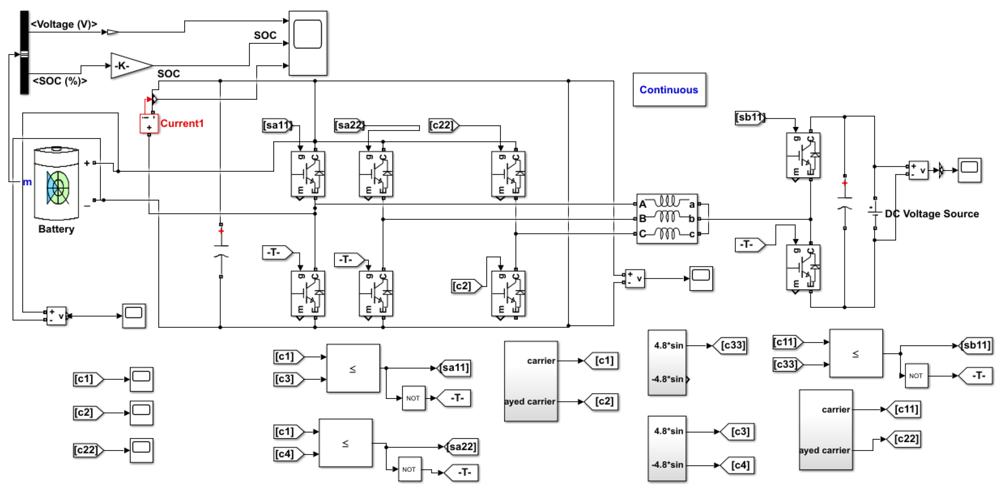
Battery chargers are among the most essential aspects of the broad adoption of electric vehicles, and their properties have an impact on battery capacity and recharging time. The charger should be quite efficient, inexpensive, and put a low strain on the system. High power factor correction is necessary, and switching device power dissipation should be kept to a minimum. Single-stage chargers are available for off-board and on-board use. Essentially, these are motor traction circuits that can be used as battery chargers. To achieve outstanding efficiency, an isolated setup design must be constructed by eliminating an interval using the more practical high-frequency converter. Isolated topologies demand more supplementary elements and components than non-isolated forms. The switching frequency of the EV model is taken as 8 kHz. The complete Simulink illustration of the NN–IPSO technique is presented in Figure 4. The stipulations of the battery-operated systems are specified in Table 1.
Figure 5 shows the performance analysis of voltage, SOC, and current waveforms for the NN–IPSO controller. The converters must provide high-quality and reliable voltage to avoid the degradation of the expensive equipment for voltage regulation. This study presents a computational method for predicting several inverter designs to determine the best converter organization for battery appearance. The battery’s SOC estimate safeguards the system against unanticipated disruptions, and prevents the batteries from becoming overcharged or drained, which could damage the batteries’ internal prearrangement.
Table 2 compares the results of several switching states in terms of THD, power loss, and efficiency. In terms of multiple limitations, the proposed isolated converter was compared to the various controllers described above. From Table 2, it is clear that the proposed NN–IPSO outperforms existing controllers in terms of THD, efficiency, and power loss. Additionally, it offers more flexibility on the load side, with a lower voltage waveform and acceptable charging conditions. The controls–filters list in the PLECS material library contains blocks that could be used to calculate power loss. Averaged conduction, switching, and total losses (via a sum block) could be accurately demonstrated by delivering the proper loss signals to such blocks from a semiconductor utilizing PLECS probe components. Those blocks were used for the calculation of losses in this research.
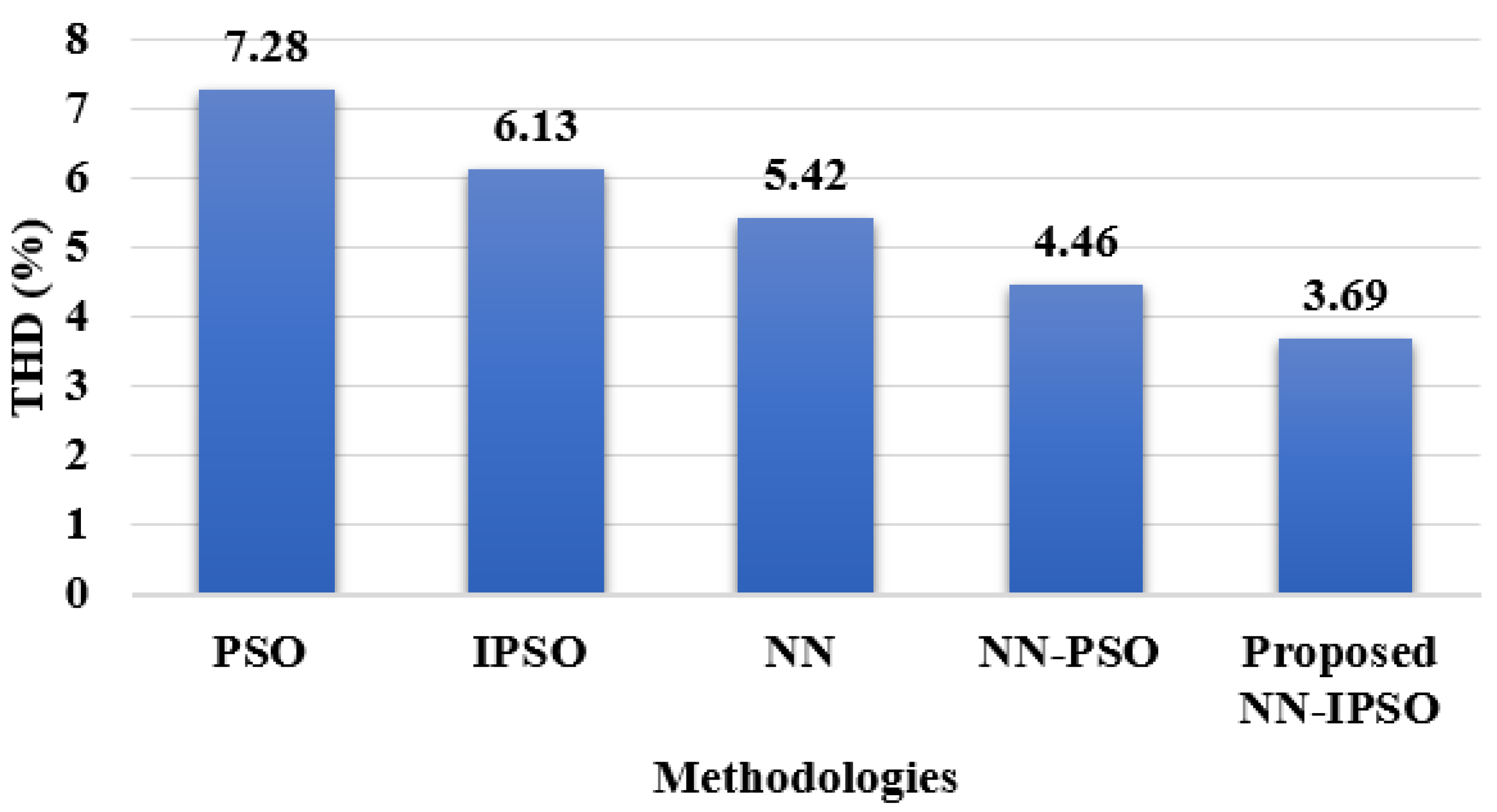
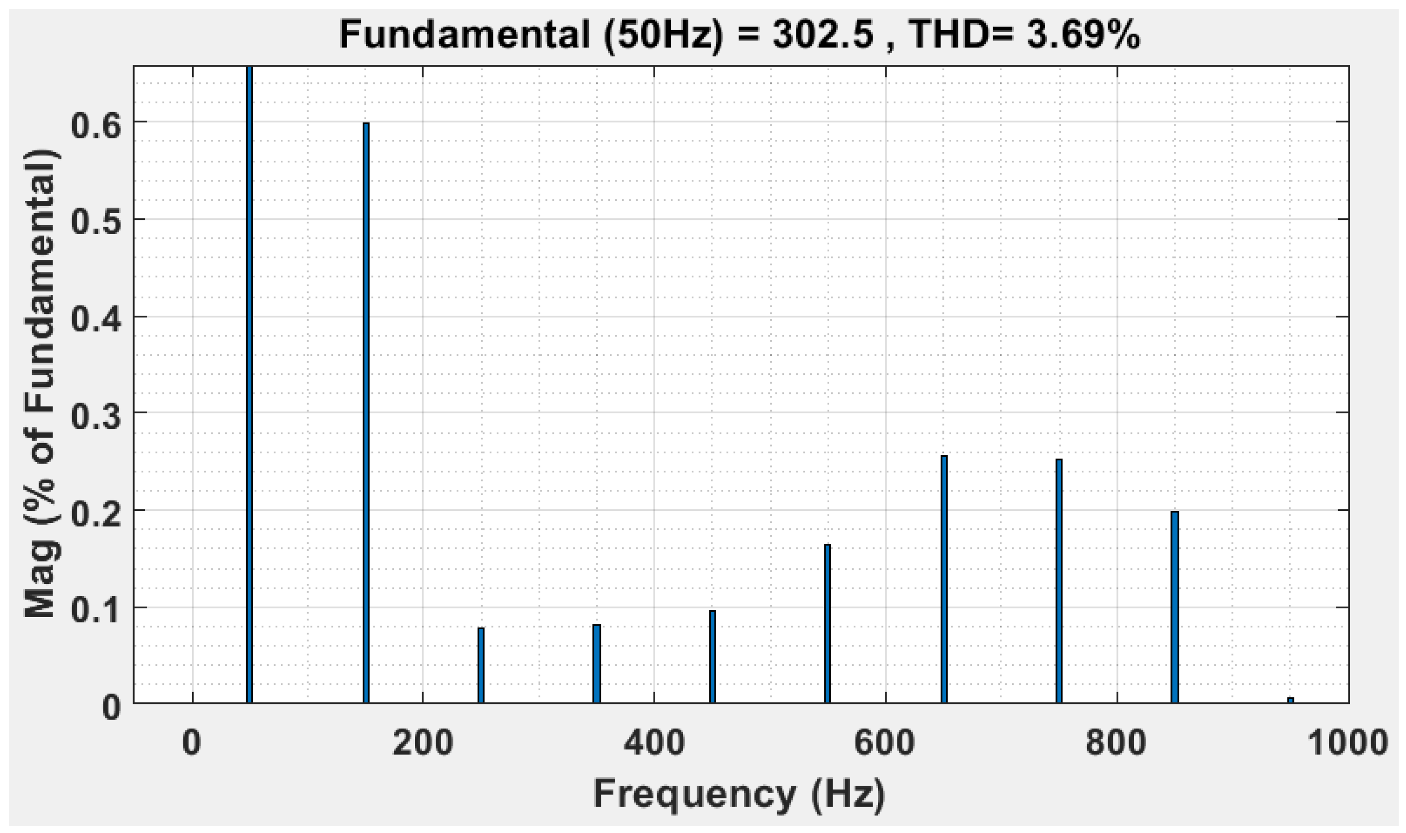
Figure 6 displays the THD calculations carried out in MATLAB. Table 3 clearly indicates that the achieved THD of the proposed NN–IPSO was 3.69%, which is less than that of existing methods. The DC link voltage does not have to be increased above the input voltage in the design procedure. In the second phase, the recommended charger layout can keep the DC–DC [33,34] converter’s efficiency as high as necessary for achieving an ultrawide output voltage range. The developed converter can charge the battery pack at 100 V and 420 V using DC link voltage management while preserving high capacitance, a close-to-unity power factor, and low THD.
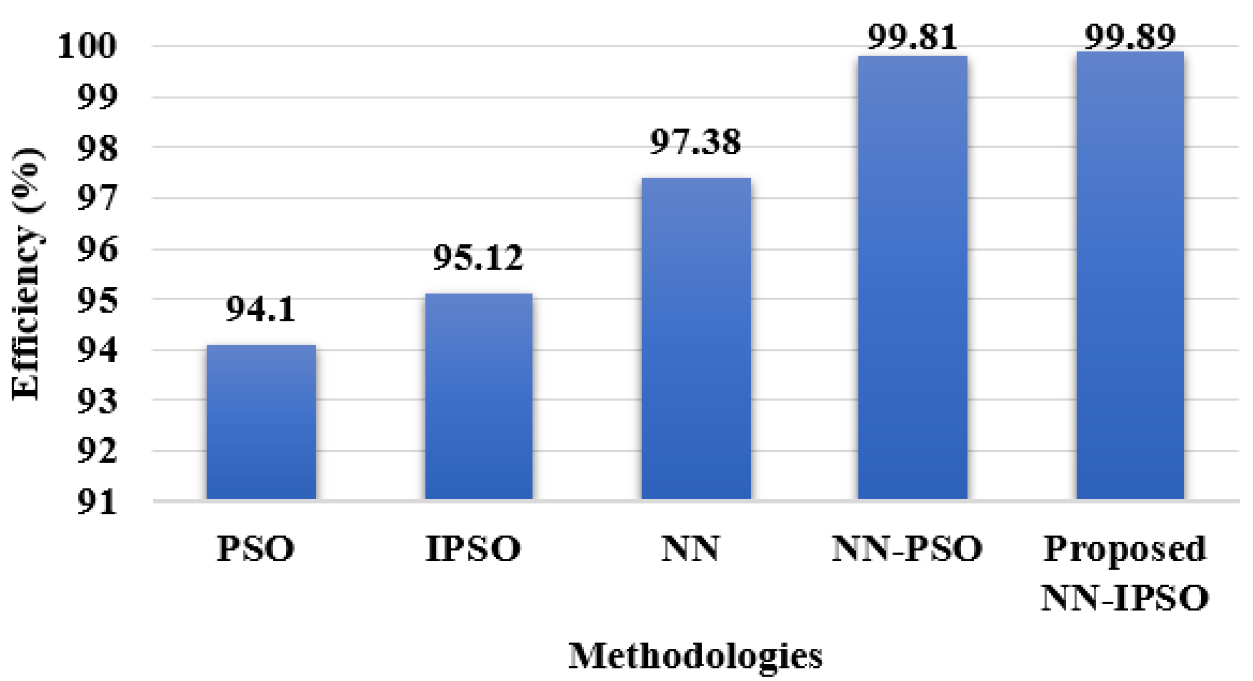
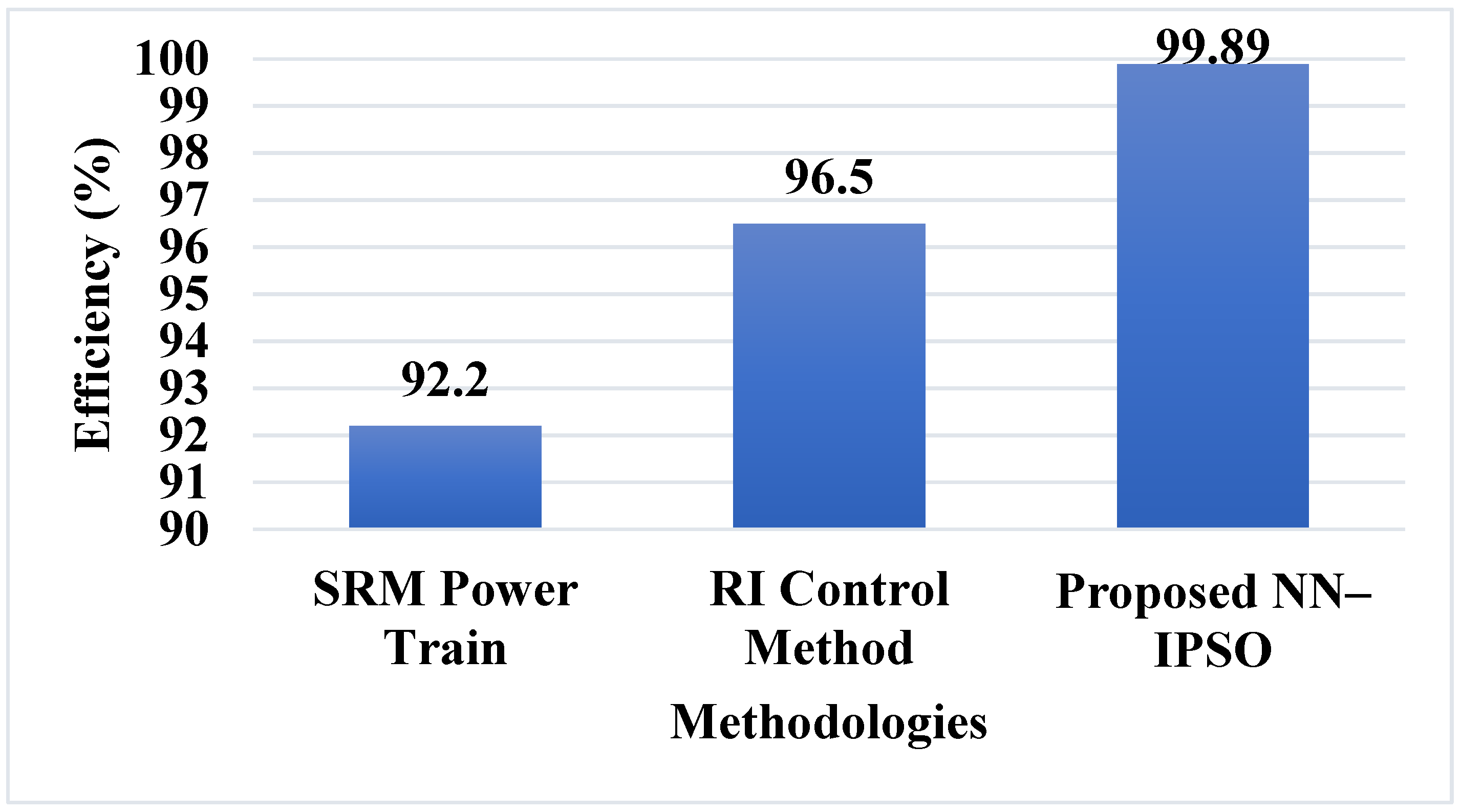
Efficiency is calculated through PLECS (Piecewise Linear Electrical Circuit Simulation) control, in which the circuit elements function within their necessary boundaries. Every block in the Semiconductor Devices library has an internal parameter that reflects the block’s instantaneous power dissipation. Only the real power that the block dissipates is included in this instantaneous dissipated power. The power dissipated by the block over time is represented by the time-value series for this parameter whenever we log the simulation results. As a result, this efficiency function is used to determine the circuit’s efficiency based on the losses for blocks with a power-dissipated parameter. Figure 7 shows the efficiency calculation for different methods, and indicates that the efficiency value for the proposed NN–IPSO method is 99.89%.
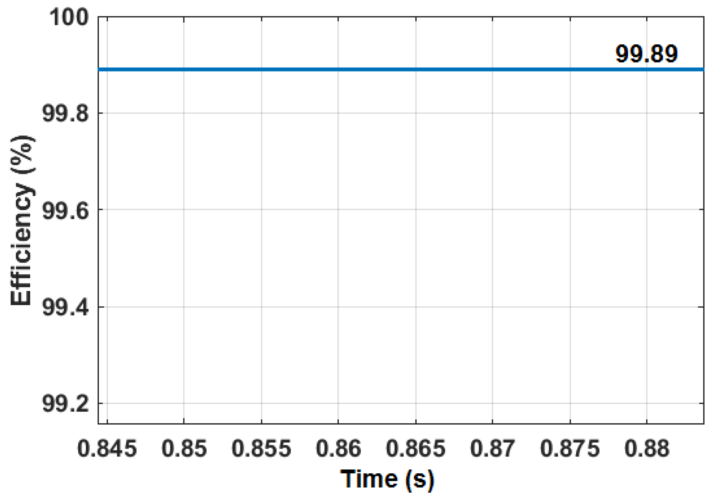
PLECS does not quite expose the thermal losses connected to the electrical domain, because the switching losses are introduced as energy impulses in zero-time. Instead, it employs the most recent junction temperature information to compute fresh thermal losses. As a result, when employing the thermal domain, the only valid computation for efficiency is to subtract the thermal losses from the power supply to predict an imbalance between a primarily electrically calculated efficiency and a recognized technique that includes ohmic losses in the switch components (on-resistances), and to attempt to evaluate the energy while including all electrical losses due to resistances in the passive elements. Figure 8 shows the efficiency value of the proposed NN–IPSO. Figure 9 shows the zoom view of the efficiency graph. An on-board PHEV battery pack depending on an isolated converter architecture is suggested in this paper. To improve the charger’s switching efficacy, the best performance for the converter design is used.
Figure 10 shows the performance analysis of power loss calculation for different methods. Figure 10 shows that the proposed NN–IPSO produced a power loss of 0.083 kW, which is less than that of existing methods. The suggested design can recharge battery packs that are highly exhausted, with voltages as low as 100 V. This design has the potential to raise and lower the input voltage that can be used in the front-end power conversion phase. In PFC applications, both steady-state assessment and AC small-signal modeling of the structure are removed. The CCM procedure is confirmed using method factors, and the voltage and current fluctuations are carefully considered. The isolated converter and inverter stages of a charger are intended to validate the evidence of perception. The computational results show that the suggested charger can support a wide voltage range while keeping the converter functioning at the preferred efficiency level.

Comparative Analysis

In [25], for the front-end converter, a quadratic RI control method is used, which recognizes a power factor nearer to one in the commutation period at varying load outputs. The RI control method completely depends upon multiphase types of machinery, and needs to be logged onto isolated plugs of engine windings. The power loss of the traction machine is incorporated with proficiency, which is much less than that of the proposed NN–IPSO. The incorporated SRM topology in [26] required additional constituents—for example, a converter or a diode bridge rectifier. The converter and rectifier are the essential parts of the non-integrated OBC design. The size and cost of the proposed charger are less than those of the remaining battery chargers [35]; subsequently, no other additional constituents are essential for the proposed charger topology. Figure 11 shows the THD analysis for the proposed on-board integrated charger with NN–IPSO. Table 3 clearly shows a comparison table of the existing methods.
Figure 12 shows the comparative analysis of efficiency and THD. Figure 12 clearly shows that the effectiveness of the proposed NN–IPSO is better than that of the existing SRM power train [26] and RI control methods [25] in terms of efficiency and THD. The electromagnetic connection of multiphase equipment affects the power factor due to the effectiveness of the proposed NN–IPSO, which is greater than that of the existing SRM power train [26] and RI control methods [25]. The THD of the proposed converter is less than that of the other existing methods. Even though the motor impedance values for different integrated stations differ, the integrated charger has the same charging appearance when using the recommended control method.

5. Conclusions

Generally, the traditional chargers operate only in charging mode to accomplish extra modes of PHEV, so a distinct topology of the converter is required to decrease the burden and losses. To improve the effectiveness of driving cars, the motor–generator combination might work together in a variety of ways. The proposed converter design not only enables the use of batteries at a cheaper price, but also offers the opportunity of controlling the inverter’s output to reduce system inefficiencies. From the outcomes, the efficiency and reliability parameters are employed to determine the most reliable topology with the least power loss when compared with existing topologies. Moreover, the proposed method divides the battery sequence and increases the functionality at high voltages. The simulation results were developed in MATLAB to demonstrate the suggested topology’s performance in battery-connected applications. The proposed NN–IPSO with an isolated converter delivers minimum losses of around 0.047 KW, an efficiency of 99.823%, and THD of 3.69%, making it substantially superior to the remaining converters. As a result, the recommended NN–IPSO topology with the isolated converter was chosen as the optimal architecture for on-board battery charger operations. The network has finished training when the error on the sample is decreased to a specific value, so it does not produce the best outcomes. Furthermore, the proposed converter can be used in AC–DC microgrids, which means that a small portion of the low-voltage distribution systems are located far from power-generating stations and linked to electricity grids via the point of common coupling. Therefore, in the future, numerous optimization approaches—such as Reptile Search Optimization or Firebug Swarm Optimization—will be used to extend this topology for various application scenarios.

Author Contributions

This paper’s investigation, resources, data curation, writing—original draft preparation, writing—review and editing, and visualization were performed by G.A. The paper’s conceptualization and software were conducted by D.B.P. The validation, formal analysis, methodology, supervision, project administration, and funding acquisition of the version to be published were conducted by W.-C.L. All authors have read and agreed to the published version of the manuscript.

Funding

This research received no external funding.

Data Availability Statement

Not applicable.

Conflicts of Interest

The authors declare no conflict of interest.

References

  1. Bai, Y.; Li, J.; He, H.; Santos, R.C.D.; Yang, Q. Optimal design of a hybrid energy storage system in a plug-in hybrid electric vehicle for battery lifetime improvement. IEEE Access 2020, 8, 142148–142158. [Google Scholar] [CrossRef]
  2. Zhou, S.; Chen, Z.; Huang, D.; Lin, T. Model prediction and rule based energy management strategy for a plug-in hybrid electric vehicle with hybrid energy storage system. IEEE Trans. Power Electron. 2020, 36, 5926–5940. [Google Scholar] [CrossRef]
  3. Kumar, D.; Nema, R.K.; Gupta, S. A comparative review on power conversion topologies and energy storage system for electric vehicles. Int. J. Energy Res. 2020, 44, 7863–7885. [Google Scholar] [CrossRef]
  4. Mozhi, S.A.; Raja, S.C.; Saravanan, M.; Nesamalar, J.J.D. Energy management of hybrid energy storage system in PHEV with various driving mode. In Artificial Intelligent Techniques for Electric and Hybrid Electric Vehicles; Chitra, A., Sanjeevikumar, P., Holm-Nielsen, J.B., Himavathi, S., Eds.; Scrivener Publishing: Beverly, MA, USA; Wiley: Hoboken, NJ, USA, 2020; pp. 103–113. [Google Scholar]
  5. Habib, S.; Khan, M.M.; Abbas, F.; Ali, A.; Faiz, T.M.; Ehsan, F.; Tang, H. Contemporary trends in power electronics converters for charging solutions of electric vehicles. CSEE J. Power Energy Syst. 2020, 6, 911–929. [Google Scholar]
  6. Yadlapalli, R.T.; Kotapati, A.; Kandipati, R.; Koritala, C.S. A review on energy efficient technologies for electric vehicle applications. J. Energy Storage 2022, 50, 104212. [Google Scholar] [CrossRef]
  7. Rathore, V.; Siddavatam, R.P.R.; Rajashekara, K. An Isolated Multilevel DC-DC Converter Topology with Hybrid Resonant Switching for EV Fast Charging Application. IEEE Trans. Ind. Appl. 2022, 58, 5546–5557. [Google Scholar] [CrossRef]
  8. Fouladi, E.; Baghaee, H.R.; Bagheri, M.; Gharehpetian, G.B. Smart V2G/G2V charging strategy for PHEVs in AC microgrids based on maximizing battery lifetime and RER/DER employment. IEEE Syst. J. 2020, 15, 4907–4917. [Google Scholar] [CrossRef]
  9. Aluisio, B.; Bruno, S.; De Bellis, L.; Dicorato, M.; Forte, G.; Trovato, M. DC-microgrid operation planning for an electric vehicle supply infrastructure. Appl. Sci. 2019, 9, 2687. [Google Scholar] [CrossRef] [Green Version]
  10. Chen, M.; Ma, S.; Wan, H.; Wu, J.; Jiang, Y. Distributed control strategy for DC microgrids of photovoltaic energy storage systems in off-grid operation. Energies 2018, 11, 2637. [Google Scholar] [CrossRef] [Green Version]
  11. Sahoo, S.K.; Sinha, A.K.; Kishore, N.K. Control techniques in AC, DC, and hybrid AC–DC microgrid: A review. IEEE J. Emerg. Sel. Top. Power Electron. 2017, 6, 738–759. [Google Scholar] [CrossRef]
  12. Wang, P.; Wang, D.; Zhu, C.; Yang, Y.; Abdullah, H.M.; Mohamed, M.A. Stochastic management of hybrid AC/DC microgrids considering electric vehicles charging demands. Energy Rep. 2020, 6, 1338–1352. [Google Scholar] [CrossRef]
  13. Azeem, O.; Ali, M.; Abbas, G.; Uzair, M.; Qahmash, A.; Algarni, A.; Hussain, M. A comprehensive review on integration challenges, optimization techniques and control strategies of hybrid AC/DC Microgrid. Appl. Sci. 2021, 11, 6242. [Google Scholar] [CrossRef]
  14. Kim, I.; Lee, S.; Park, J.-W. Design and Control of OBC-LDC Integrated Circuit with Variable Turns Ratio for Electric Vehicles. In Proceedings of the IEEE Energy Conversion Congress and Exposition (ECCE), Detroit, MI, USA, 11–15 October 2020; pp. 885–890. [Google Scholar]
  15. Fan, Y.; Li, W.; Liu, B.; Jin, M.; Ren, X.; Xu, C.; Diao, L. Evaluation Model of Loop Stray Parameters for Energy Storage Converter of Hybrid Electric Locomotive. IEEE Access 2020, 8, 212589–212598. [Google Scholar] [CrossRef]
  16. Baek, J.; Youn, H.-S. Full-bridge active-clamp forward-flyback converter with an integrated transformer for high-performance and low cost low-voltage DC converter of vehicle applications. Energies 2020, 13, 863. [Google Scholar] [CrossRef] [Green Version]
  17. Bak, Y.; Kang, H.-S. Control Methods for Performance Improvement of an Integrated On-Board Battery Charger in Hybrid Electric Vehicles. Electronics 2021, 10, 2506. [Google Scholar] [CrossRef]
  18. Chen, J.; Yang, C.; Tang, S.; Zou, J. A High Power Interleaved Parallel Topology Full-Bridge LLC Converter for Off-Board Charger. IEEE Access 2021, 9, 157790–157799. [Google Scholar] [CrossRef]
  19. Bayati, M.; Abedi, M.; Farahmandrad, M.; Gharehpetian, G.B.; Tehrani, K. Important Technical Considerations in Design of Battery Chargers of Electric Vehicles. Energies 2021, 14, 5878. [Google Scholar] [CrossRef]
  20. Yuan, J.; Dorn-Gomba, L.; Callegaro, A.D.; Reimers, J.; Emadi, A. A review of bidirectional on-board chargers for electric vehicles. IEEE Access 2021, 9, 51501–51518. [Google Scholar] [CrossRef]
  21. Ramos, L.A.; Van Kan, R.F.; Mezaroba, M.; Batschauer, A.L. A Control Strategy to Smooth Power Ripple of a Single-Stage Bidirectional and Isolated AC-DC Converter for Electric Vehicles Chargers. Electronics 2022, 11, 650. [Google Scholar] [CrossRef]
  22. Elshaer, M.; Bell, C.; Hamid, A.; Wang, J. DC–DC Topology for Interfacing a Wireless Power Transfer System to an On-Board Conductive Charger for Plug-In Electric Vehicles. IEEE Trans. Ind. Appl. 2021, 57, 5552–5561. [Google Scholar] [CrossRef]
  23. Nam, V.; Tinh, D.; Choi, W. A Novel Hybrid LDC Converter Topology for the Integrated On-Board Charger of Electric Vehicles. Energies 2021, 14, 3603. [Google Scholar] [CrossRef]
  24. Zinchenko, D.; Blinov, A.; Chub, A.; Vinnikov, D.; Verbytskyi, I.; Bayhan, S. High-Efficiency Single-Stage On-Board Charger for Electrical Vehicles. IEEE Trans. Veh. Technol. 2021, 70, 12581–12592. [Google Scholar] [CrossRef]
  25. Kanimozhi, G.; Natrayan, L.; Angalaeswari, S.; Paramasivam, P. An Effective Charger for Plug-In Hybrid Electric Vehicles (PHEV) with an Enhanced PFC Rectifier and ZVS-ZCS DC/DC High-Frequency Converter. J. Adv. Transp. 2022, 2022, 7840102. [Google Scholar] [CrossRef]
  26. He, C.; Wang, Z.; Yang, S.; Huang, J.; Ge, X. An Integrated SRM Powertrain Topology for Plug-In Hybrid Electric Vehicles with Multiple Driving and On-board Charging Capabilities. IEEE Trans. Transp. Electrif. 2020, 6, 578–591. [Google Scholar]
  27. Viana, C.; Lehn, P.W. A drivetrain integrated DC fast charger with buck and boost functionality and simultaneous drive/charge capability. IEEE Trans. Transp. Electrif. 2019, 5, 903–911. [Google Scholar] [CrossRef]
  28. Lee, F.C.; Li, Q.; Nabih, A. High frequency resonant converters: An overview on the magnetic design and control methods. IEEE J. Emerg. Sel. Top. Power Electron. 2020, 9, 11–23. [Google Scholar] [CrossRef]
  29. Attia, H. Artificial neural network based unity power factor corrector for single phase DC-DC converters. Int. J. Electr. Comput. Eng. 2020, 10, 4145. [Google Scholar] [CrossRef]
  30. Sabanci, K.; Balci, S. Development of an expression for the output voltage ripple of the DC-DC boost converter circuits by using particle swarm optimization algorithm. Measurement 2020, 158, 107694. [Google Scholar] [CrossRef]
  31. Chen, Z.; Wang, Y.; Chan, T.H.T.; Li, X.; Zhao, S. A Particle Swarm Optimization Algorithm with Sigmoid Increasing Inertia Weight for Structural Damage Identification. Appl. Sci. 2022, 12, 3429. [Google Scholar] [CrossRef]
  32. Anandhi, P.; Harikrishnan, S.; Kumar, V.J.S.; Lai, W.-C.; Mahmoud, A.E.D. The Enhanced Energy Density of rGO/TiO2 Based Nanocomposite as Electrode Material for Supercapacitor. Electronics 2022, 11, 1792. [Google Scholar] [CrossRef]
  33. Lai, W.-C.; Jian, R.; Xiaoning, X. DC-DC Converter and Rectifier with Resonator for Underwater Wireless Power Transfer Module. In Proceedings of the 2020 IEEE International Conference on Consumer Electronics-Taiwan (ICCE-Taiwan), Taoyuan, Taiwan, 28–30 September 2020. [Google Scholar]
  34. Lai, W.-C. DC-DC Converter and Rectifier with Resonator for Solar and Wireless Charging in Advanced Driver Assistance Systems. In Proceedings of the 2019 IEEE 4th International Future Energy Electronics Conference (IFEEC), Singapore, 25–28 November 2019. [Google Scholar]
  35. Girirajan, B.; Shekhar, H.; Lai, W.-C.; Jagannathan, H.K.; Divakarachar, P.B. High Gain Converter with Improved Radial Basis Function Network for Fuel Cell Integrated Electric Vehicles. World Electr. Veh. J. 2022, 13, 31. [Google Scholar] [CrossRef]
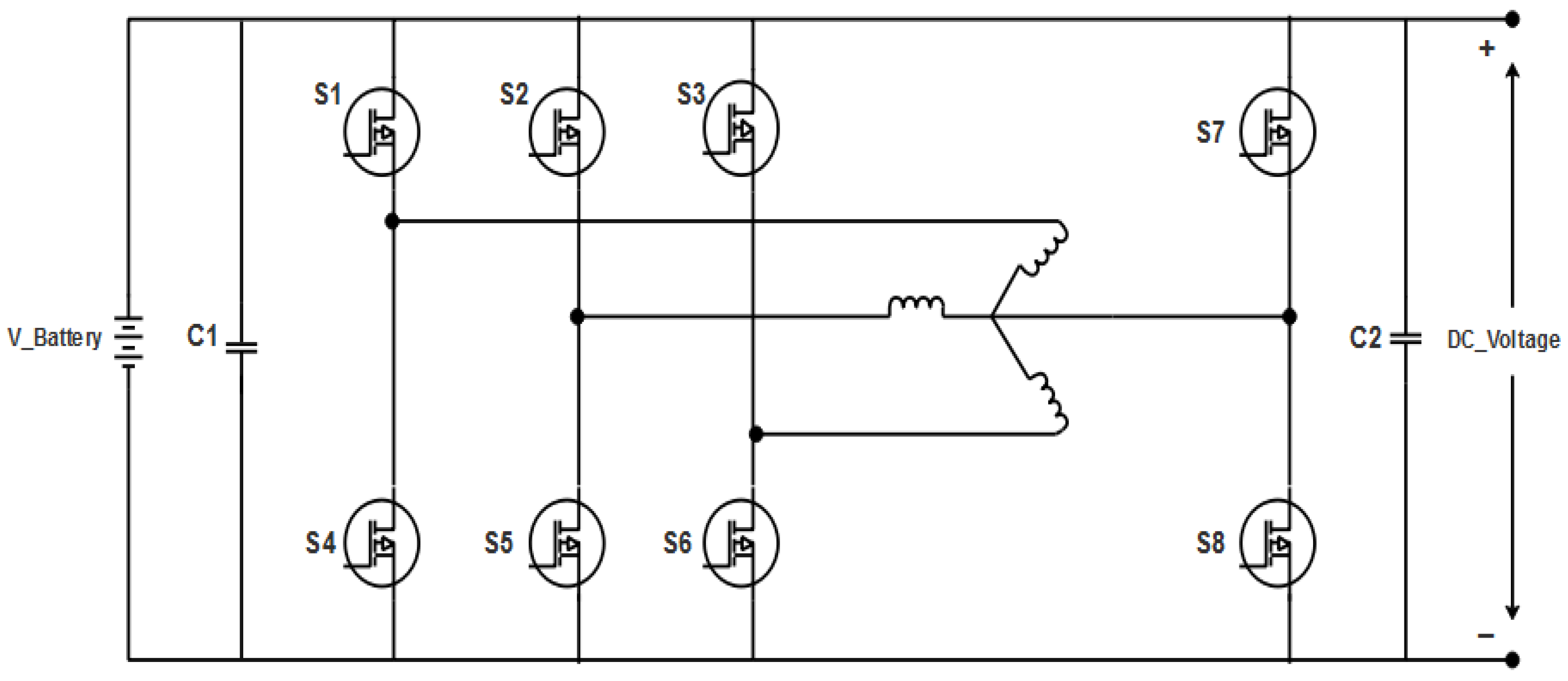
Figure 1. Circuit diagram of the bidirectional converter.
Wevj 13 00196 g001
Figure 2. General block diagram of the battery-based converter.
Wevj 13 00196 g002
Figure 3. Flowchart of the proposed method.
Wevj 13 00196 g003
Figure 4. Simulink model for the NN–IPSO controller.
Wevj 13 00196 g004
Figure 5. Performance analysis of voltage, SOC, and current waveforms for the Neural Network–Improved Particle Swarm Optimization (NN–IPSO) controller.
Wevj 13 00196 g005
Figure 6. Comparison of Total Harmonic Distortion.
Wevj 13 00196 g006
Figure 7. Performance analysis of efficiency.
Wevj 13 00196 g007
Figure 8. Efficiency of Neural Network–Improved Particle Swarm Optimization (NN–IPSO).
Wevj 13 00196 g008
Figure 9. Zoom view of efficiency.
Wevj 13 00196 g009
Figure 10. Power loss performance.
Wevj 13 00196 g010
Figure 11. Performance of fast Fourier transform analysis.
Wevj 13 00196 g011
Figure 12. Comparative analysis of existing methods [25,26].
Wevj 13 00196 g012
Table 1. Specifications of the isolated converter.
ComponentsRatings
Battery voltage 230   V
Capacitance C1, C2
Inductance L1, L2
220   mF
47   mH
DC voltage 260   V
Flux linkage 0.6   V s
Resistance 95   m
Rotational friction coefficient 0.1   Nms / rad
Rotational inertia 0.767   kgm
Switching frequency 10   kHz
Table 2. Performance of various controllers.
Isolated TopologyTHD %Efficiency %Power Loss (KW)
PSO controller7.2894.100.163
IPSO controller6.1395.120.129
NN controller5.4297.380.105
NN–PSO controller4.4699.810.091
Proposed NN–IPSO controller3.6999.890.083
Table 3. Comparison table of existing methods.
PerformanceSRM Power Train [26]RI Control Method [25]Proposed NN–IPSO
Efficiency92.296.599.89
THD4.95-3.69
Publisher’s Note: MDPI stays neutral with regard to jurisdictional claims in published maps and institutional affiliations.