1. Introduction
Currently, traditional vehicles are being swapped for electric vehicles (EV) due to the discharge of foul gases and ecological pollution [
1,
2]. So, electric vehicle practice is improving. Solar power and electric vehicle chargers are crucial to decreasing our dependence on fossil fuels and represent the usual progress of our energy structure.
Two key inclinations in energy custom that are anticipated for the impending future are the enhancement in distributed generation such as sun energy and the advent of electric vehicles (EV) as the imminent means of conveyance [
3]. Additionally, there are numerous concerns for the mixing of these two growing systems. Primarily, electric vehicles are “ecofriendly till the basis of power is ‘ecofriendly’”. On the other hand, photovoltaic (PV) solar energy-capturing suffers from daytime and cyclical disparities, causing a requirement for energy stowage technology. Thirdly, congestion and voltage issues are anticipated in the dispersed network due to the fast increase in renewable generation and the increased power requirement for the fueling of electric vehicles. To overcome the above concerns, producing electric vehicles using PV energy would be a better answer, ensuring an emission-free system.
EVs can be categorized into various types; one of the types is a plug-in electric vehicle (PEV). The PEV motor is operational on the battery influence [
4]. The batteries are re-energized from an outdoor posting of electricity. The change of AC to DC is essential to revive the battery, as the battery store is DC. Alteration of AC/DC functions on high frequency switches and power quality concerns such as harmonics, neutral currents and reactive power need rises. Various FACTS (Flexible AC Transmission Systems) devices are applied for various power quality issues, among them DSTATCOM is mainly used for current-based power quality issues.
The DSTATCOM provides fast regulation of dynamic and responsive powers to adjust load requirements, to mitigate harmonic currents, and for voltage variations. The implementation of the DSTATCOM depends upon the control algorithm used to evaluate the reference currents. Instantaneous reactive power theory is used for the generation of reference currents. A number of control methods in a certain time domain are reported in the literature. As the traditional controllers are constant in nature, they provide optimal action only over a restricted range of operating situations for which they are developed [
5]. Alternative controllers based on fuzzy logic and neural networks are vigorous and can be developed to function well under a broad range of operating situations [
6,
7]. More vigorous controllers such as the fuzzy logic method are needed for the DSTATCOM to deliver suitable dynamic voltage regulation and to enhance the power quality and stability of the distribution network [
8]. The neural network approach is frequently used in recent times for nonlinear filtering-based networks [
9]. “A back propagation through time base learning method and a new recurrent adaptive control theory” was presented in [
10]. Since fuzzy is acting as a decision maker, it can be thoroughly considered as a member of the AI family. Fuzzy-based expert networks can be trained using ANN (Artificial Neural Network) learning methods, to merge the benefits of together in a common controller [
11,
12,
13]. The control approach is applied to mitigate the power quality issues raised at the charging stations due to the continuous conversion of AC/DC and vice versa. The power converters used at charging stations are considered as load, which are non-linear in nature. In this paper, the DSTATCOM is developed based on voltage source converter (VSC) and a new control technique is applied based on the adaptive neuro-fuzzy inference system (ANFIS). The data set is trained using a back propagation algorithm and the decisions taken by the fuzzy expert system. The proposed work is evaluated using MATLAB simulation for various loading conditions. The results obtained are compared with the conventional controllers to establish the hypothesis that ANFIS is the best for mitigating the PQ (Power Quality) issues.
2. EV Charging System: Power Quality Issues
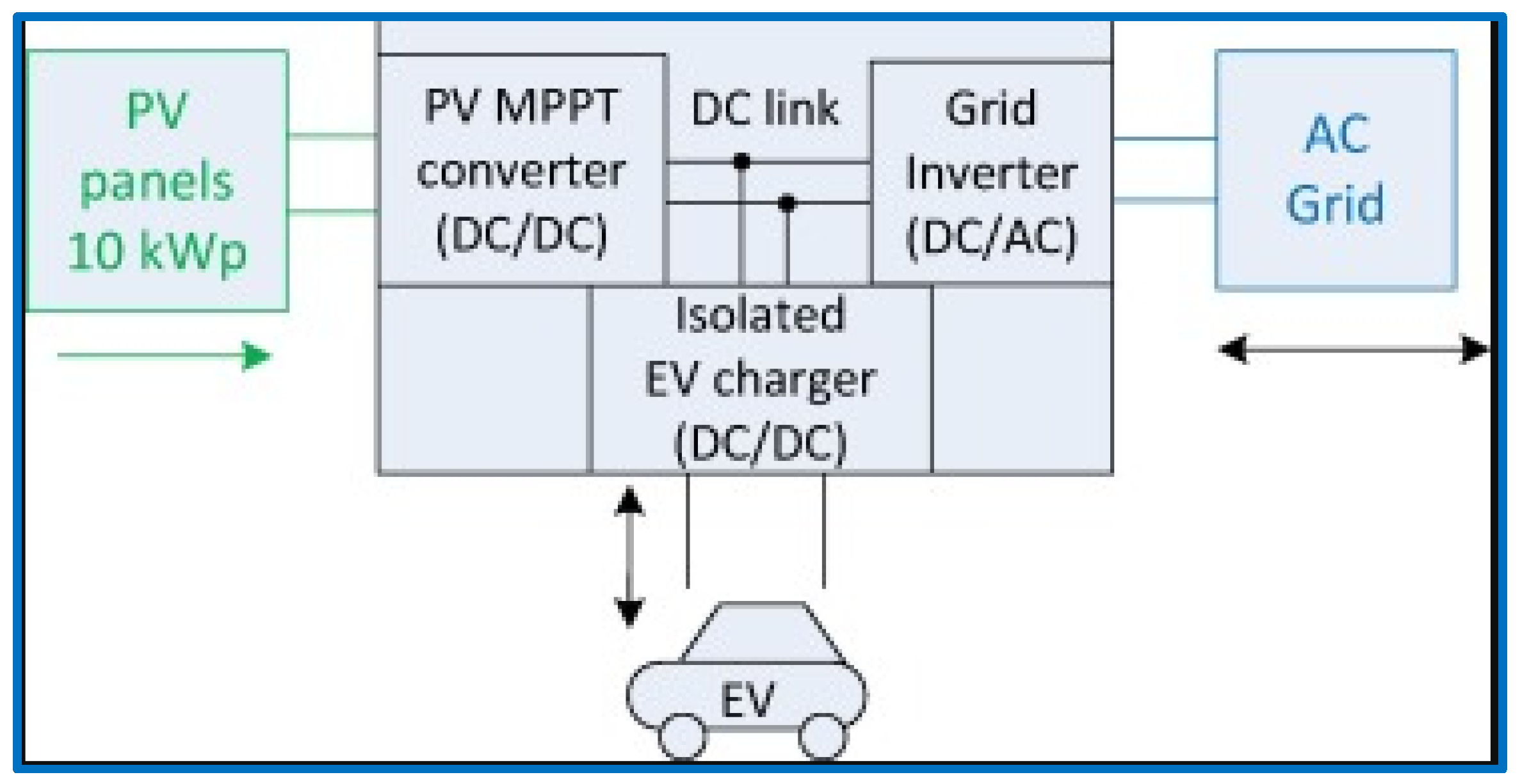
The charger has separate docks for the grid and EV and they are two-way in direction, and one single-way port for PV. The chopper, grid inverter and the DC EV charger are connected on a common DC-link. Direct connection of EV and PV on DC would be much better than AC connection due to a smaller number of energy conversion steps and enhanced efficiency [
5,
6]. The basic structure of the charging system is shown in
Figure 1. Many Maximum Power Point Tracking (MPPT) techniques are available in the literature. Here, incremental conductance is used, and super lift chopper is used as a PV converter.
The modern electric vehicle charging network has many issues that should be met to send qualitative power in a steadfast manner [
7]. This paper discusses the various power quality (PQ) problems due to EV charging system, their causes, and effects. The quality of electric power distributed is defined by two factors, namely “continuity” of supply and the “eminence” of voltage. The major power quality issues are tabulated below in
Table 1 from the literature [
14,
15,
16,
17,
18,
19,
20,
21,
22,
23,
24,
25,
26,
27].
Custom power devices (CPD) play a significant role in the mitigation of power quality concerns. Among the mitigation approaches of power quality concerns, UPQC responds to voltage sags/swells, flicker, voltage unbalance, and load unbalance.
D-STATCOM overcomes poor power factor and harmonics. It also acts as a filter, voltage controller at the delivery bus, and load compensator [
8,
9,
10].
3. DSTATCOM ANFIS Controller
Use of power devices or equipment representing fluctuating loads leads to distortions in the power quality such as harmonics, reactive power problems, etc. As a result, we obtain outputs with a low power factor, reduced efficiency, heating of machines, misfire of devices which has high sensitivity etc. An additional power quality issue is due to the use of single or three-phase unbalanced and nonlinear loads, which causes excess current to flow through neutral wire. In addition, other power quality issues cause excess overload on the neutral wire. The unbalance in source voltage also occurred due to unbalanced load unbalanced. The unbalanced terminal parameters could generate harmonics of a lower order. Thus, for the generation of a negative sequence component of current, and in the case of electric drive the torque may also drop. These quality issues are treated using power devices such as DVR, DSTATCOM etc., among which the DSTATCOM is suitable for reactive power issue and harmonic current extenuation in the distribution side compared to other devices [
11,
12].
DSTATCOM is a VSC with capacitor at the DC side. If battery is connected at the DC side, then it can supply only active power, but when capacitor is connected it will supply or absorb reactive power. In general, to operate VSC six gating pulses are required for its power switch i.e., IGBT; these pulses can be obtained using ANFIS Controller. The controller provides a good response by reducing some of high order disturbances, but the system speed will be reduced. The system speed reduces due to the usage, due to fewer membership functions and more training data.
The developed ANFIS-based DSTATCOM proposed to improve the power quality of the 3-ph 4W system is shown in
Figure 2. The proposed system operates in a three-phase balanced mode of action, while addressing unbalanced and non-linear loads. The system consists of a four-leg IGBT-based voltage source converter (VSC), solar PV array, DC/DC converter and a DC bus capacitor. VSC is interconnected with the system at the PCC (point of common coupling) using coupling impedance. Bidirectional DC/DC converter is used here at the DC side of the VSC to boost the voltage level. The switching pulses are generated by using the hysteresis controller using the reference currents generated by the ANFIS controller. The AC side of the VSC is connected to the grid and the fourth leg of VSC is linked to neutrals of both grid and load. So, load does not draw any harmonics from the neutral of the grid, which, in turn, decreases the losses in neutral wire of grid and enhances the power quality of 3P4W system in censoriously unbalanced loading situations.
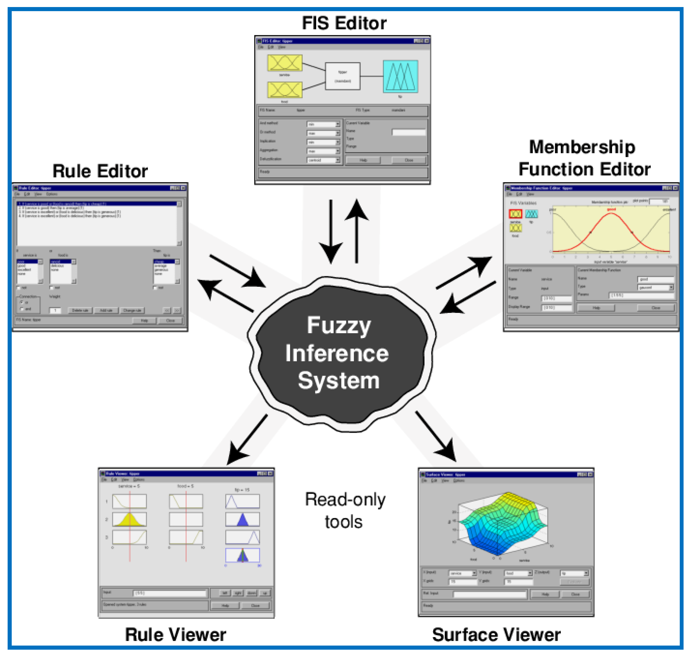
Figure 3 reflects the basic structure of fuzzy inference system used in the ANFIS controller. The fuzzy logic designer unlocks and shows a diagram of the fuzzy inference block with the titles of each input mutable on the left, and those of each output mutable on the right. The membership function editor shows the membership functions related to all of the input and output mutable for the entire fuzzy inference block. Based on the definition of the input and output variables stated with the fuzzy logic designer, the rule editor consents to frame the rule statements inevitably. Once all are stated, we can check them using rule viewer; the rule viewer shows a roadmap of the whole fuzzy inference procedure. It reflects the fuzzy inference block. We can see the entire output surface of the network, and we can look into the surface viewer.
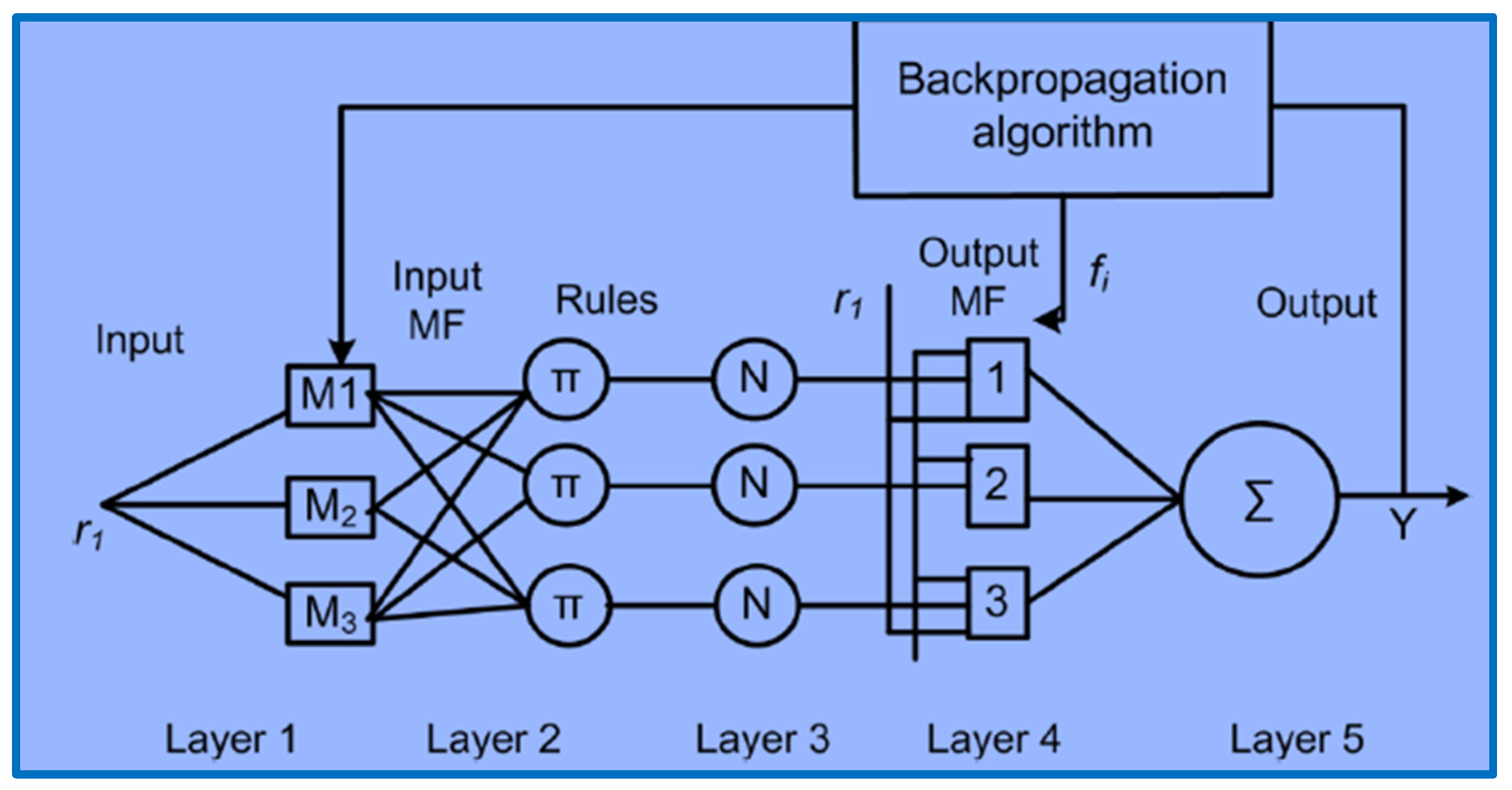
The configuration of an ANFIS comprises three membership functions, one input and three rules, as shown in
Figure 4. This figure also reflects the various adaptive abilities, which are shown with square and circle nodules. The Takagi Sugeno-type fuzzy network based ANFIS controller is applied for regulation of the hysteresis controller.
Each nodule in layer 1 is shown by a square. This layer is meant for change of crisp value to fuzzy value and termed as the fuzzification layer. In layer 2, every nodule is constant and named as Π. The output of each nodule in this layer reflects the firing potential. The output of this layer is the multiplication of input signals. Each nodule in layer 3 is shown with a circle and performs normalization of firing potential of rules. Each nodule of layer 4 is shown by a square, and nodule functions as a constraint set. This is the output layer, which contains a single neuron shown as a circle. This neuron totals the output as the sum of all incoming values.
The back propagation algorithm is used to train the ANFIS structure. This algorithm is of a gradient descent type and performs to categorize parameters. The parameters are applied to revise the fuzzy membership functions as given in layer 1. The error reduction is carried out with the gradient descent method; the variation in each constraint must be linear to the rate of variation of the error function with respect that constraint.
4. Simulation Results and Analysis
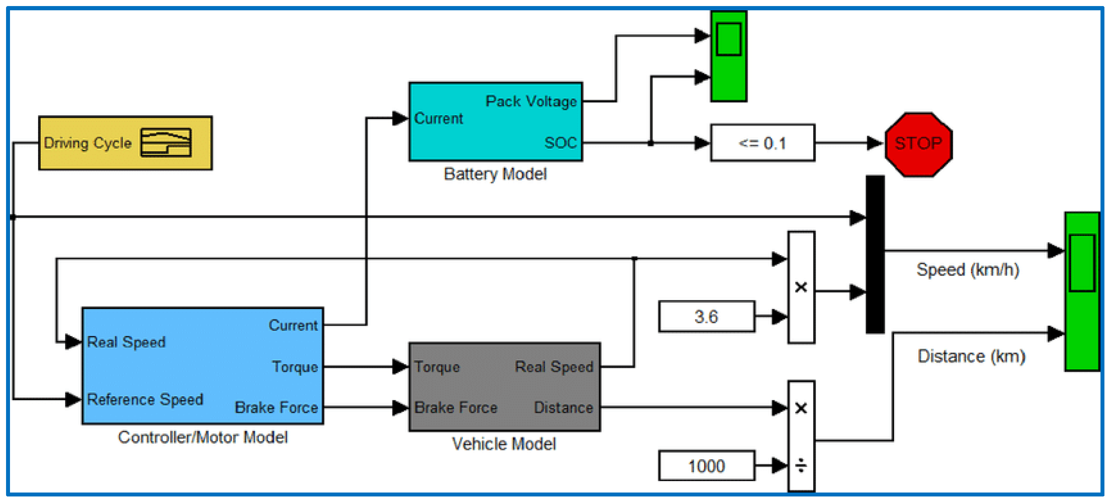
The electric vehicle motor with variable speed is considered as the load, and the basic simulation of electric vehicle is taken from the MATLAB examples and is shown in
Figure 5. The desired speed is compared with the real speed and the error is used to generate duty cycle of the converter, which will provide the voltage required for achieving the desired speed. The controller will change the force, torque and current as per the vehicle demand. The DSTATCOM is modelled using the MATLAB SIMULINK 2021a version and the proposed ANFIS controller is modelled using the fuzzy logic inference tool, as shown in
Figure 6 and
Figure 7.
Instantaneous reactive power theory is used to generate the reference currents which, in turn, compared with the actual currents and the pulses, will be generated as shown in
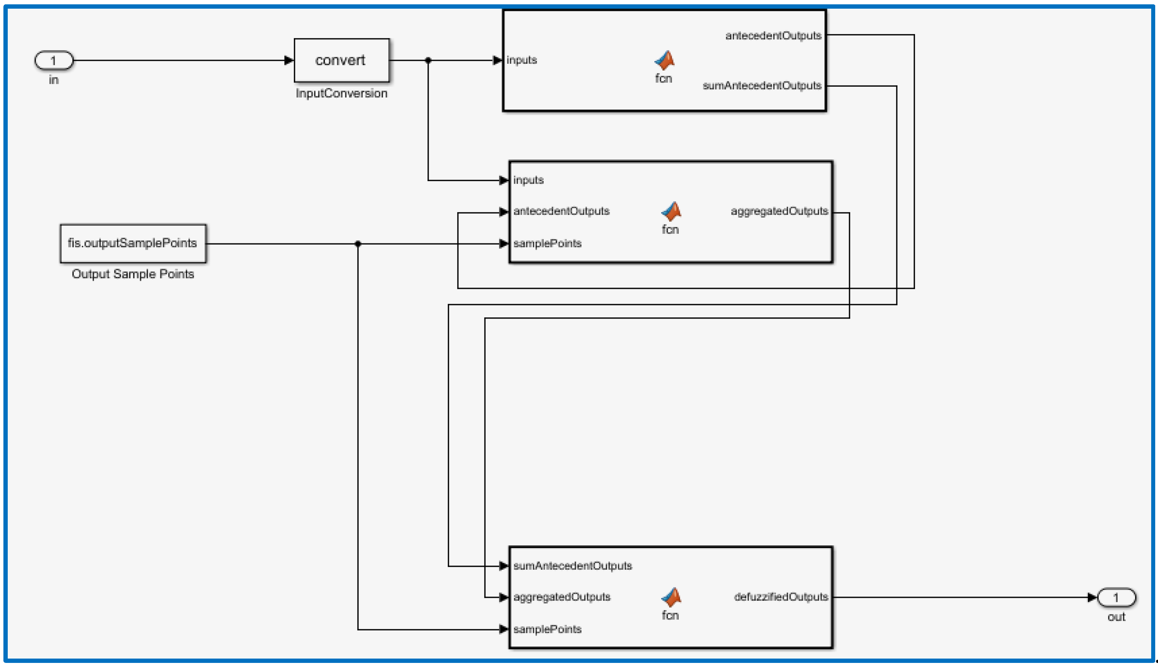
Figure 6. The desired DC voltage is compared with the actual DC voltage and the error is fed to the ANFIS controller instead of the PI controller to generate the error; this is termed as the reference d-axis current component. The generated d-axis current component is compared with the actual d-axis current component of load. The AC voltage is used to generate the q-axis reference current. These reference currents are compared with the d-q currents of the load to generate errors which are converted back to a-b-c reference currents. These are compared with actual load currents and pulses are generated for the VSC. The ANFIS controller mathematical Simulink model is shown in
Figure 7.
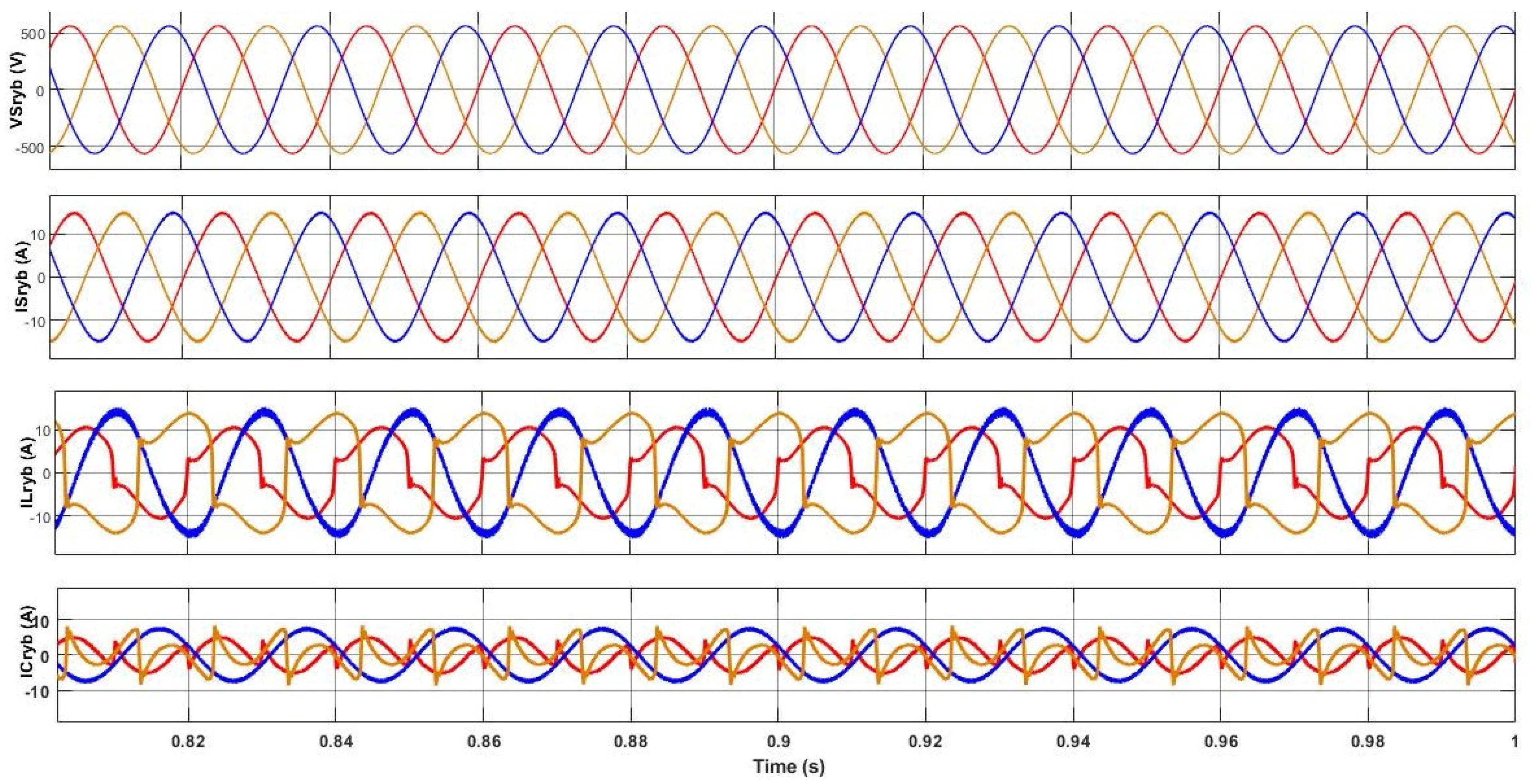
The simulation results shown in
Figure 8 reflect the source voltages and source currents, which are purely sinusoidal compared to the load currents, which are non-sinusoidal and unbalanced. The harmonics required for the non-linear loads are injected in shunt using VSI reflected as a compensation current.
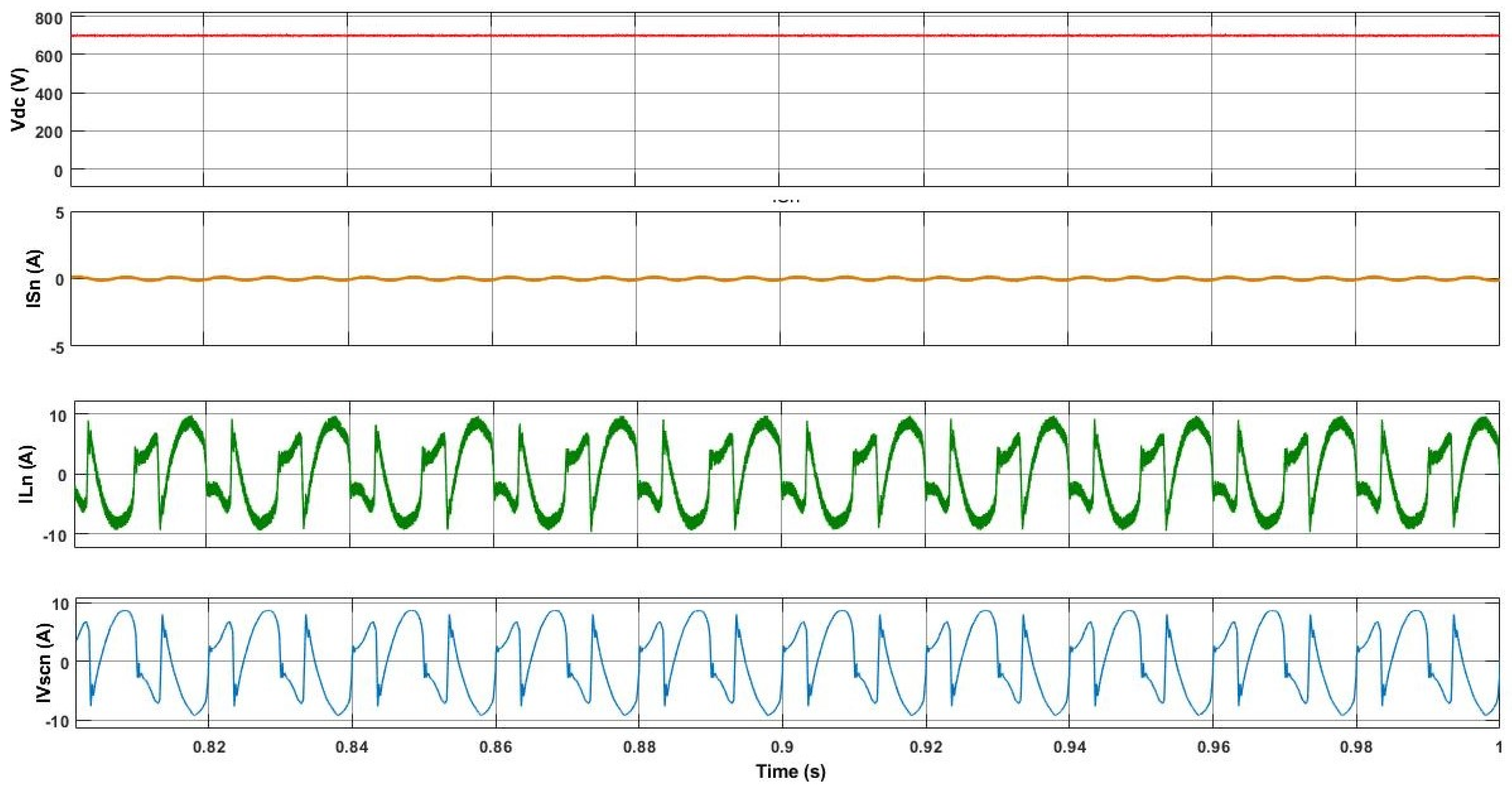
The simulated results shown in
Figure 9 reflects that the harmonic current demanded by load neutral has been entirely recompensed by the fourth leg of the converter. Therefore, this neutral current recompense ability of the system, the neutral of the input is not obligatory to distribute any harmonic element of load-neutral current. The input neutral current
(isn) load neutral current
(iln) and converter neutral current
(ivscn) are shown in
Figure 9.
The simulated results in
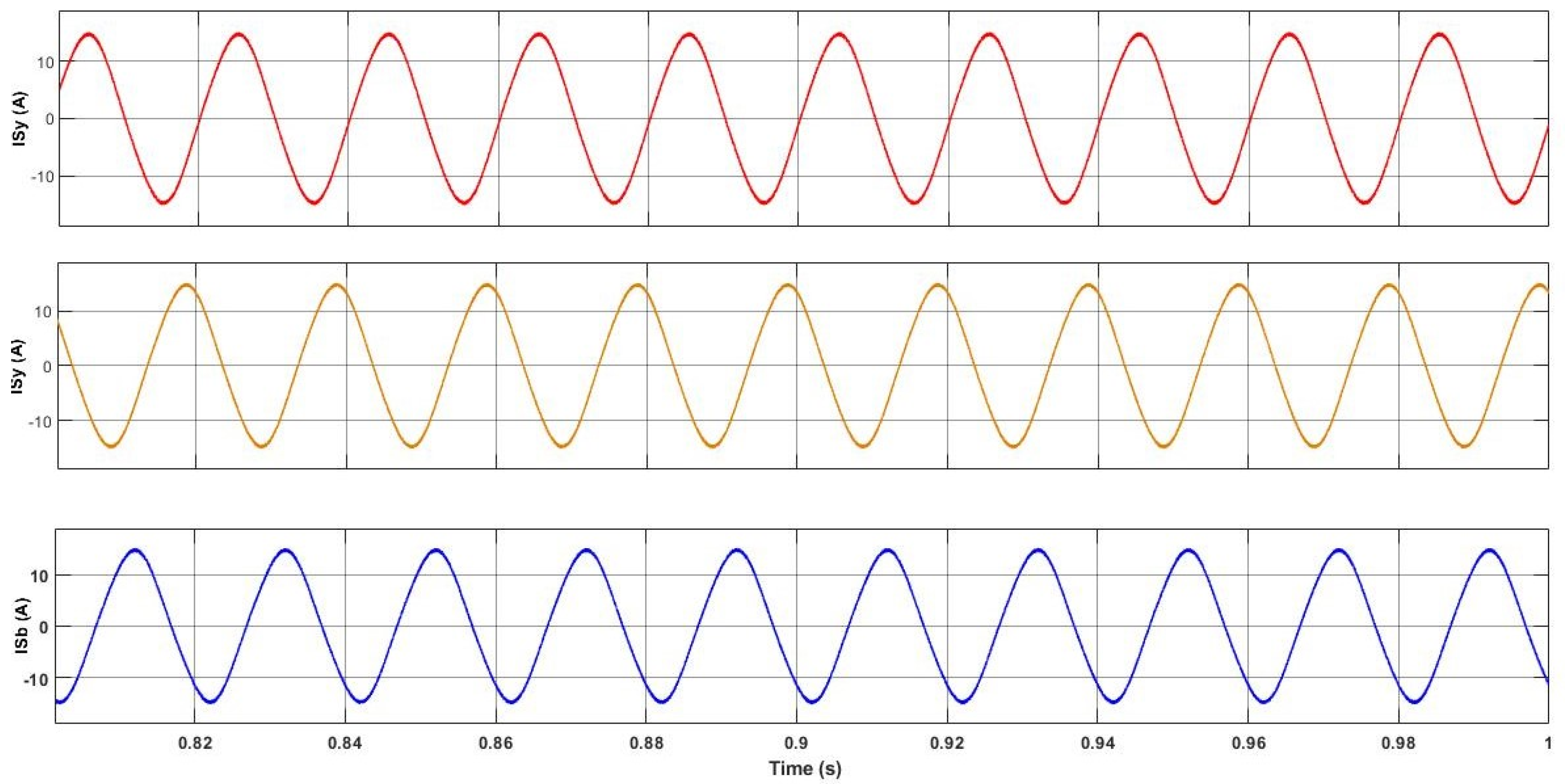
Figure 10 also reflect that the profiles of current of loads in the three phases are different. The simulated results in
Figure 11 present that the three phase currents of input are impeccably balanced, identical and sinusoidal, when the station has three various types of single-phase loads.
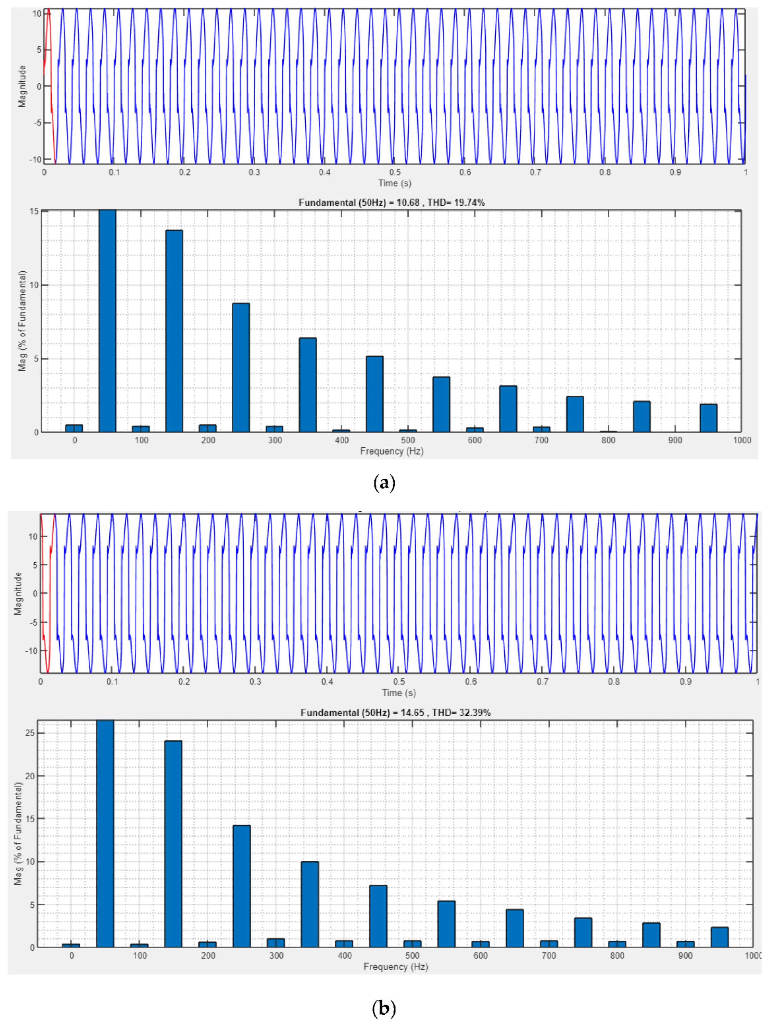
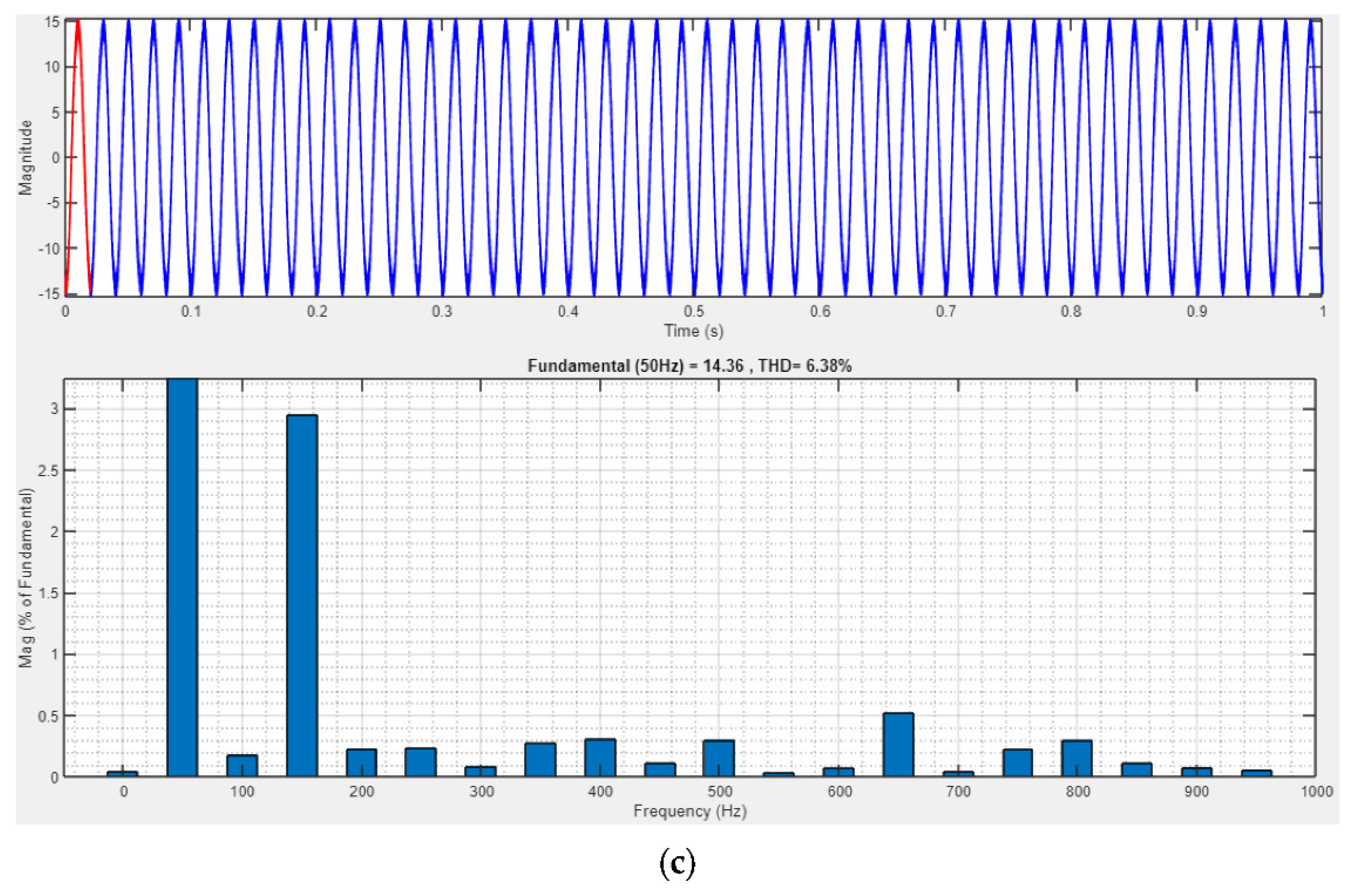
Figure 12 represents the THD of three-phase unbalanced loads.
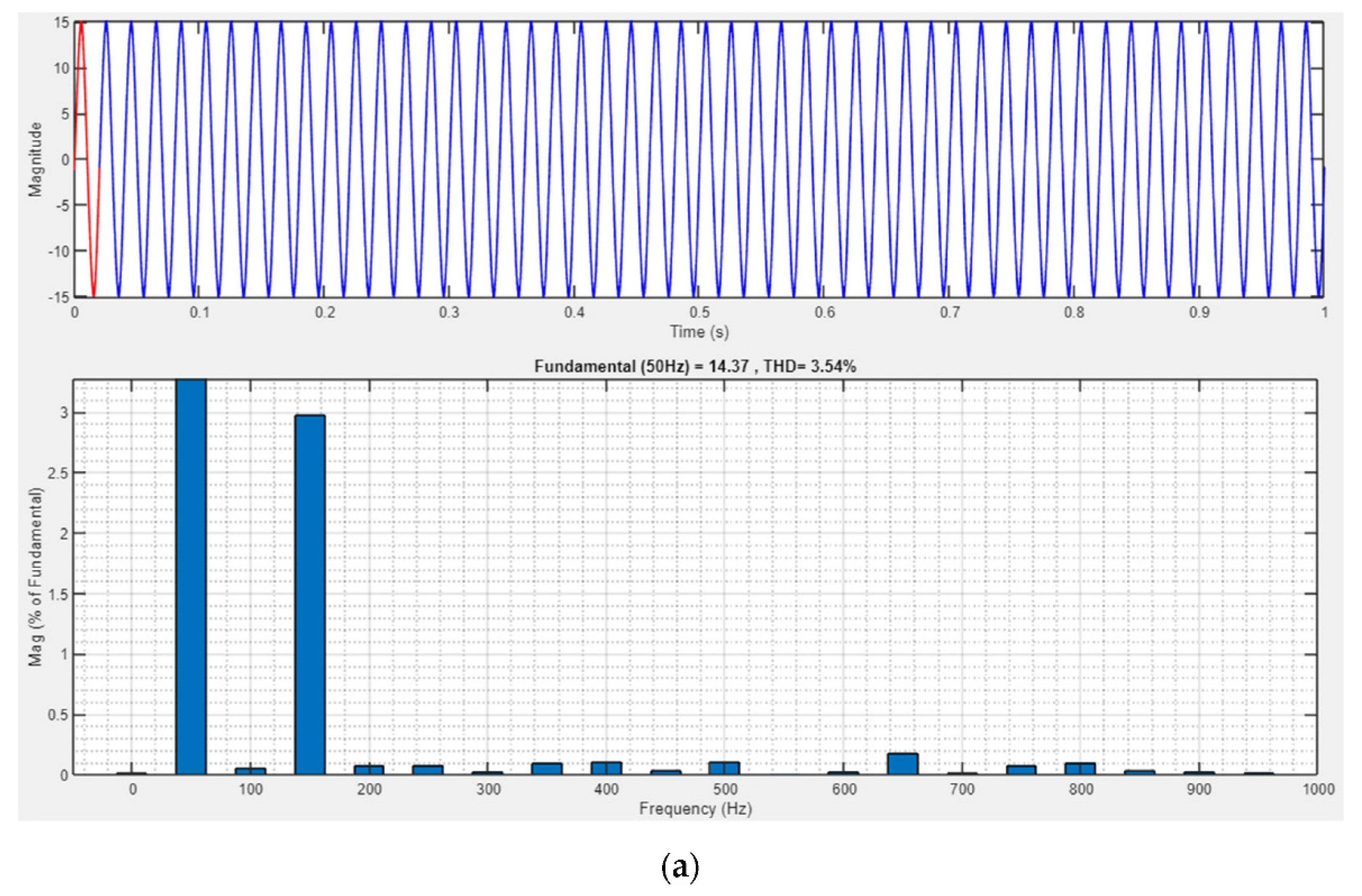
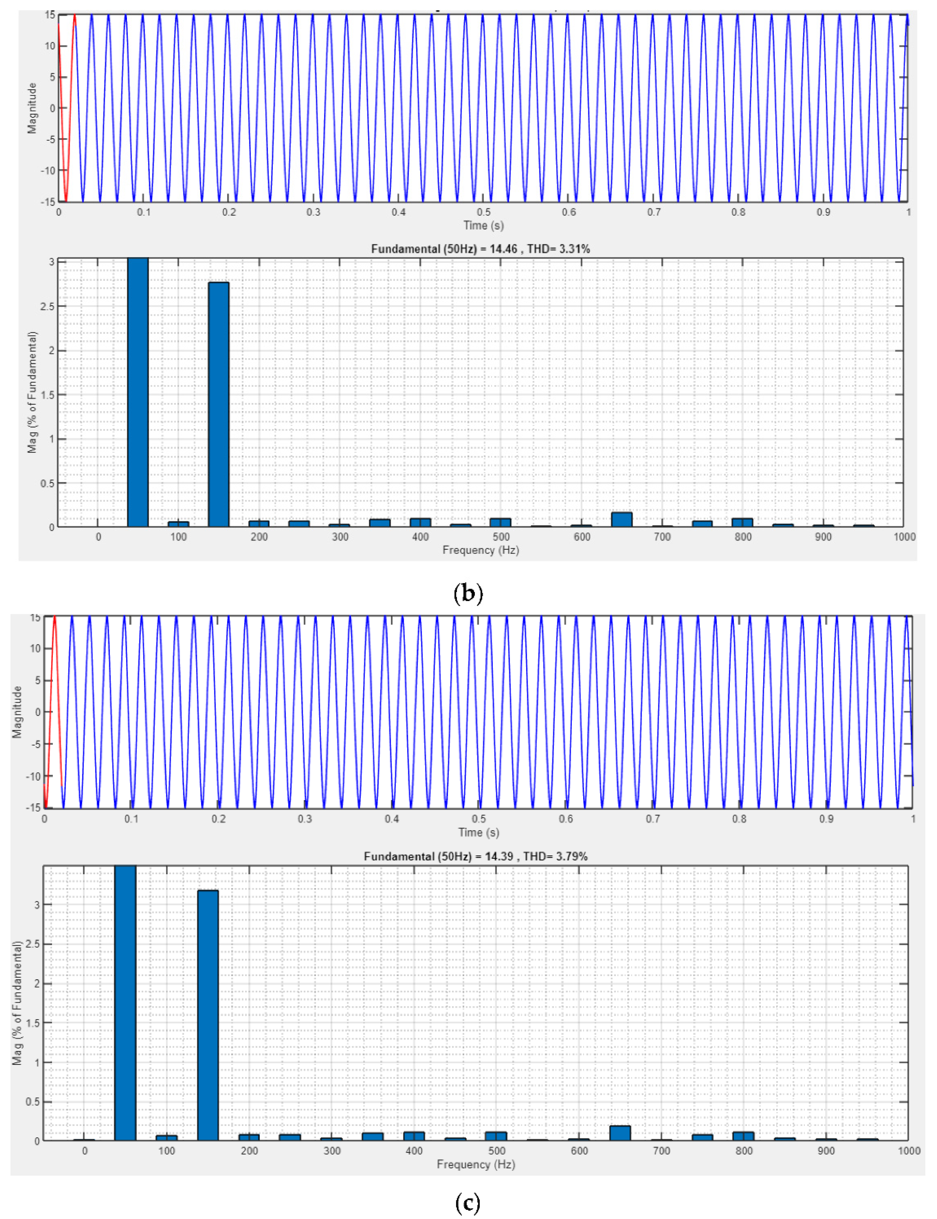
Figure 13a–c shows the signals and THDs of currents at load side.
Figure 13a–c shows that the THD at input current is below 5%, so the developed system follows the IEEE 519 standard. The THD of R-phase load is 19%, the THD of Y-phase is 32% and the THD of the B-phase is 6%, whereas the THDs of all three phases of the source currents are around 3%, thus enhancing the power quality of the system under dynamic load variations using adaptive controller.
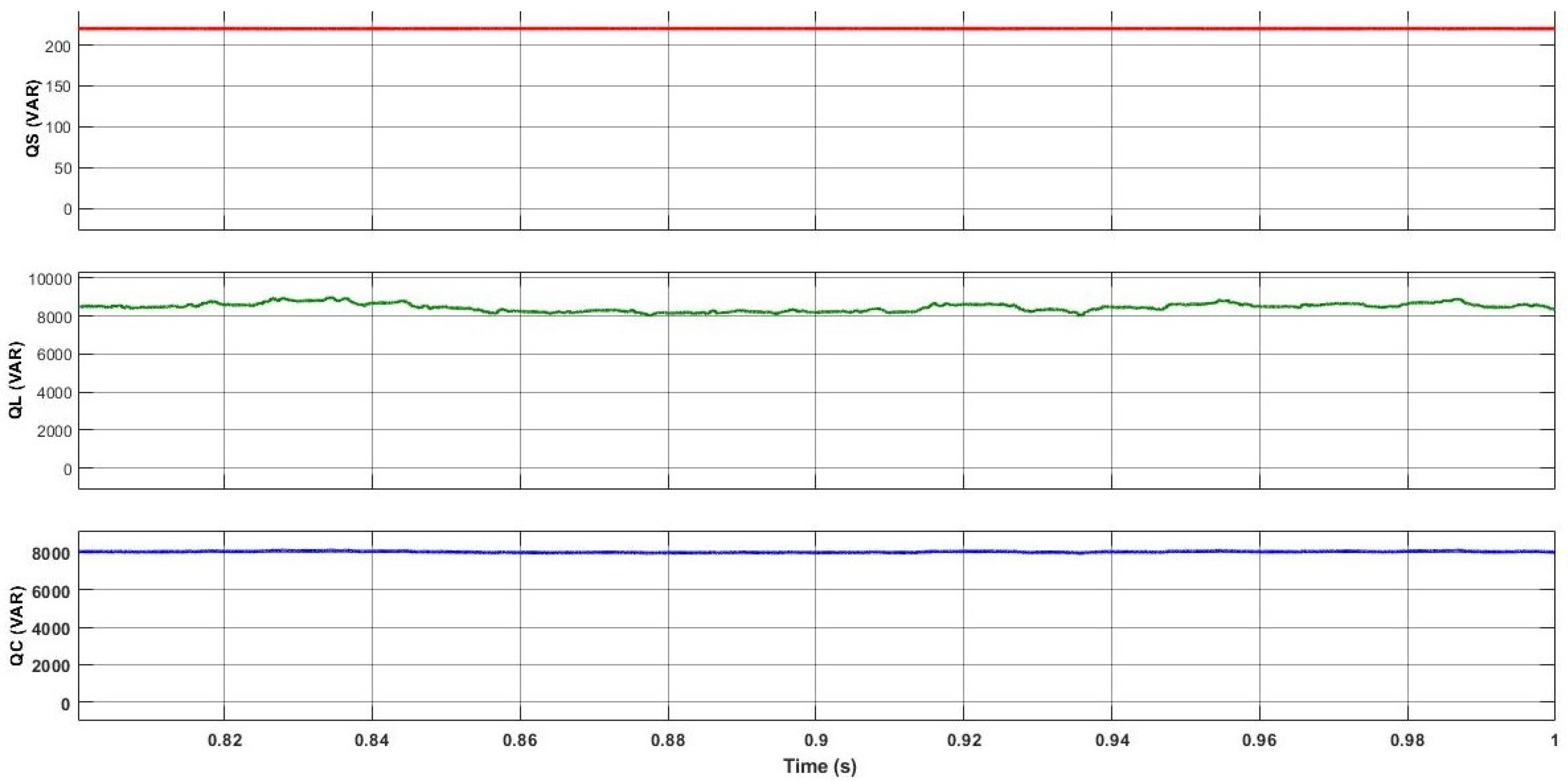
Figure 14 reflects the powers injected to 3P4W distribution network, i.e., both the active and reactive, load demand and converter requirement. The required active power supplied to the distribution system is from source and reactive power is negligible and power factor is improved to unity. Moreover, the necessary reactive power by load is provided by four-leg VSC, as shown in
Figure 14.
The THD value of the unbalanced loading condition using ANFIS controller is compared with the (recent 2020 published) ZSI supported DSTATCOM, whose IGBTs switching pulses are developed by using the ISCT control technique as shown in
Table 2. Good improvement in the THD is observed using the proposed PV-based DSTATCOM.
5. Conclusions
This paper has demonstrated the ANFIS-based DSTATCOM for electric vehicle charging station. The impact of harmonics and unbalanced currents happens in the input side due to non-linearities and the reactive nature of load in charging stations. DSTATCOM mitigates power quality challenges by using the ANFIS-based instantaneous reactive power control technique and HCC. The proposed topology is evaluated under unbalanced conditions and the performance is satisfactory. The supply currents of all phases observed are balanced and the THD of the input current fulfils the IEEE-519–1992 standard rules regarding the harmonic boundary. The reactive power demand of the charging station is also addressed by the proposed DSTATCOM.
Source current harmonics (R-Ph) = 3.54%.
Load current harmonics (R-Ph) = 19.74%.
Author Contributions
Conceptualization, M.M.I. and S.S.R.; methodology, software, validation, M.M.I., S.S.R., E.R.C. and T.S.; investigation, resources, writing—original draft preparation, writing—review and editing, visualization; supervision; project administration, M.M.I., S.S.R., E.R.C. and T.S. All authors have read and agreed to the published version of the manuscript.
Funding
This research received no external funding.
Conflicts of Interest
The authors declare no conflict of interest.
References
- Susan Anenberg, G.; Joshua, M. A Global Snapshot of the Air Pollution-Related Health Impacts of Transportation Sector Emissions in 2010 and 2015; ICCT: Washington, DC, USA, 2009. [Google Scholar]
- Balakrishnan, K.; Dey, S.; Gupta, T.; Dhaliwal, R.S.; Brauer, M.; Cohen, A.J.; Stanaway, J.D.; Beig, G.; Joshi, T.K.; Aggarwal, A.N.; et al. India State-Level Disease Burden Initiative: The impact of air pollution on deaths, disease burden, and life expectancy across the states of India: The Global Burden of Disease Study 2017. Lancet Planet. Health 2019, 3, e26–e39. [Google Scholar] [CrossRef] [Green Version]
- Vidhi, R.; Shrivastava, P. A Review of Electric Vehicle Lifecycle Emissions and Policy Recommendations to Increase EV Penetration in India. Energies 2018, 11, 483. [Google Scholar] [CrossRef]
- Gelmanova, Z.; Zhabalova, G.; Sivyakova, G.; Lelikova, O.; Onishchenko, O.; Smailova, A.; Kamarova, S. Electric cars. Advantages and disadvantages. J. Phys. Conf. Ser. 2018, 1015, 052029. [Google Scholar] [CrossRef] [Green Version]
- Farokhnia, N.; Fathi, S.H.; Khoraminia, R.; Hosseinian, S.H. Optimization of PI coefficients in DSTATCOM nonlinear controller for regulating DC voltage using Genetic Algorithm. In Proceedings of the 4th IEEE Conference on Industrial Electronics and Applications (2009), Xi’an, China, 25–27 May 2009; pp. 2291–2296. [Google Scholar]
- Jiang, Y.; Yang, C.; Ma, H. A Review of Fuzzy Logic and Neural Network Based Intelligent Control Design for Discrete-Time Systems. Dyn. Nat. Soc. 2016, 2016, 11. [Google Scholar] [CrossRef] [Green Version]
- Shi, J.; Noshadi, A.; Kalam, A.; Shi, P. Fuzzy logic control of DSTATCOM for improving power quality and dynamic performance. In Proceedings of the 2015 Australasian Universities Power Engineering Conference (AUPEC), Brisbane, Australia, 27 September 2015; pp. 1–6. [Google Scholar] [CrossRef]
- Vassilyev, S.N.; Kudinov, Y.I.; Pashchenko, F.F.; Durgaryan, I.S.; Kelina, A.Y.; Kudinov, I.Y.; Pashchenko, A.F. Intelligent Control Systems and Fuzzy Controllers. II. Trained Fuzzy Controllers, Fuzzy PID Controllers. Autom. Remote Control 2020, 81, 922–934. [Google Scholar] [CrossRef]
- Jain, V.; Tyagi, M. ANN Control of DSTATCOM for Improving Power Quality and Dynamic Performance. IJRECE 2019, 7, 2719–2721. [Google Scholar]
- Singh, B.; Arya, S.R. Back-Propagation Control Algorithm for Power Quality Improvement Using DSTATCOM. IEEE Trans. Ind. Electron. 2014, 61, 1204–1212. [Google Scholar] [CrossRef]
- Varshney, A.; Garg, R.; Kumar, N. Implementation of ANFIS Control Scheme for DSTATCOM, 2nd ed.; International Conference on Power Energy, Environment and Intelligent Control (PEEIC): Greater Noida, India, 2019. [Google Scholar]
- Mittal, C.; Srivastava, S. Comparison of ANN and ANFIS Controller Based Hysteresis Current Control Scheme of DSTATCOM for Fault Analysis to Improve Power Quality. In Proceedings of the International Conference on Electronics and Sustainable Communication Systems (ICESC 2020), Coimbatore, India, 2–4 July 2020. [Google Scholar]
- Jagadeesh, V.; M.Mangaraj, S.; Madhuri, K. ZSI supported DSTATCOM for Plug-in Electrical Vehicle charging station. In Proceedings of the IEEE International Conference on Computational Intelligence for Smart Power System and Sustainable Energy (CISPSSE-2020), Odisha, India, 29–31 July 2020. [Google Scholar]
- Tahir, Z.; Ahmadu, G.; Aminu, M. Review of Motors for Electrical Vehicles. J. Sci. Res. Rep. 2019, 24, 1–6. [Google Scholar]
- Vidyanandan, K.V. Batteries for Electric Vehicles Project Report at NTPC; NTPC Power Management Institute: Noida, India, 2019. [Google Scholar]
- Ismail, A.; Jung, W.; Ariffin, M.F.; Noor, S.A. Study of Electric Vehicle Battery Reliability Improvement. Int. J. Reliab. Appl. 2011, 12, 123–129. [Google Scholar]
- Mouli, G.C.; Bauer, P.; Zeman, M. System design for a solar powered electric vehicle charging station for workplaces Appl. Energy 2016, 168, 434–443. [Google Scholar]
- House, M.L.; Wright, D.J. Using the health benefits of electric vehicles to justify charging infrastructure incentives. Int. J. Electr. Hybrid Veh. 2019, 11. [Google Scholar] [CrossRef]
- Mandrile, F.; Cittanti, D.; Mallemaci, V.; Bojoi, R. Electric Vehicle Ultra-Fast Battery Chargers: A Boost for Power System Stability? World Electr. Veh. J. 2021, 12, 16. [Google Scholar] [CrossRef]
- Sam, C.A.; Jegathesan, V. Bidirectional integrated on-board chargers for electric vehicles—A Review. Indian Acad. Sci. 2020. [Google Scholar] [CrossRef]
- Sudhakar, A.V.; Rajababu, D.; Sathyavani, B. Analysis of the power losses in both DC side and AC side cascaded converters. Int. J. Recent Technol. Eng. 2019, 8, 897–899. [Google Scholar]
- Mudi, J.; Shiva, C.K.; Vedik, B.; Mukherjee, V. Frequency Stabilization of Solar Thermal-Photovoltaic Hybrid Renewable Power Generation Using Energy Storage Devices. Iran. J. Sci. Technol. Trans. Electr. Eng. 2020, 45, 597–617. [Google Scholar] [CrossRef]
- Vedik, B.; Naveen, P.; Shiva, C.K. A novel disruption based symbiotic organisms search to solve economic dispatch. Evol. Intell. 2020. [Google Scholar] [CrossRef]
- Rajababu, D.; Sudhakar, A.V.; Sathyavani, B. Development of technology for high-power industry converters. Int. J. Innov. Technol. Explor. Eng. (IJITEE) 2019, 8, 3130–3132. [Google Scholar]
- Ahmadi, A.; Tavakoli, A.; Jamborsalamati, P.; Rezaei, N.; Miveh, M.; Gandoman, H.; Esmaeel, F.; Nezhad, A. Power quality improvement in smart grids using electric vehicles: A review. IET Electr. Syst. Transp. 2019. [Google Scholar] [CrossRef]
- Alghsoon, E.; Harb, A.; Hamdan, M. Power quality and stability impacts of Vehicle to grid (V2G) connection. In Proceedings of the 8th International Renewable Energy Congress (IREC), Amman, Jordan, 21–23 March 2017; pp. 1–6. [Google Scholar] [CrossRef]
- Ahmed, F.S.; Hussain, A.N.; Ali, A.J. Ali Power quality improvement by using multiple sources of PV and battery for DSTATCOM based on coordinated design. IOP Conf. Ser. Mater. Sci. Eng. 2020, 745, 012025. [Google Scholar] [CrossRef]
Figure 1.
Basic structure of EV charging system.
Figure 1.
Basic structure of EV charging system.
Figure 2.
Structure of proposed D-STATCOM.
Figure 2.
Structure of proposed D-STATCOM.
Figure 3.
Fuzzy inference system.
Figure 3.
Fuzzy inference system.
Figure 4.
Sugeno inference system based ANFIS structure.
Figure 4.
Sugeno inference system based ANFIS structure.
Figure 5.
Simulation of an electric vehicle.
Figure 5.
Simulation of an electric vehicle.
Figure 6.
Simulink model of D-STATCOM controller.
Figure 6.
Simulink model of D-STATCOM controller.
Figure 7.
Simulink model of ANFIS controller.
Figure 7.
Simulink model of ANFIS controller.
Figure 8.
VSryb: input voltages, ISryb: input currents, ILryb: load currents, and ICryb: compensating currents.
Figure 8.
VSryb: input voltages, ISryb: input currents, ILryb: load currents, and ICryb: compensating currents.
Figure 9.
Vdc: DC link voltage, ISn: input neutral current, ILn: load neutral current, and IVscn: compensator neutral current.
Figure 9.
Vdc: DC link voltage, ISn: input neutral current, ILn: load neutral current, and IVscn: compensator neutral current.
Figure 10.
ILr: R-phase load current, ILy: Y-phase load current, and ILb: B-phase load current.
Figure 10.
ILr: R-phase load current, ILy: Y-phase load current, and ILb: B-phase load current.
Figure 11.
ISr: R-phase input current, ISy: Y-phase input current and ISb: B-phase input current.
Figure 11.
ISr: R-phase input current, ISy: Y-phase input current and ISb: B-phase input current.
Figure 12.
(a) R-phase load current THD, (b) Y-phase load current THD, and (c) B-phase load current THD.
Figure 12.
(a) R-phase load current THD, (b) Y-phase load current THD, and (c) B-phase load current THD.
Figure 13.
(a) R-phase input current THD, (b) Y-phase input current THD, and (c) B-phase input current THD.
Figure 13.
(a) R-phase input current THD, (b) Y-phase input current THD, and (c) B-phase input current THD.
Figure 14.
QS: Source reactive power, QL: load reactive power, and QC: Compensator reactive power.
Figure 14.
QS: Source reactive power, QL: load reactive power, and QC: Compensator reactive power.
Table 1.
PQ Issues, causes and consequences.
Table 1.
PQ Issues, causes and consequences.
| Type of PQ Issue | Description | Causes | Consequences |
|---|
| Voltage sag | A reduction in the usual voltage level from 10% to 90% of the standard rms voltage just at power frequency over a period of 0.5 to 1 min. | Fault on the network for transmission or delivery (most of the times on parallel times on parallel feeders). Fault in deployment for user’s operation of heavy loads and start-up of motor drivers. | Misfire of IT equipment i.e., microprocessor-based control systems (PCs, PLCs, AFDs etc) which may respond to process cessation.
Contactor and tripping electromechanical relays. |
| Voltage swell | Increased voltage instantly, at power frequency, beyond standard tolerances, lasting longer than one cycle and usually less than a few seconds. | Heavy loads start/stop, badly configured power sources, poorly operated transformers (primarily during the off hours). | Data loss, illumination and screen blinking, stopping or harming sophisticated equipment when the voltage value is too large. |
| Harmonic distortion | In shape, voltage or current waveform are often non-sinusoidal. The waveform refers to the number of various sinewaves with distinct amplitude and phase, of frequencies which are multiple frequency of the power system. | Electro-machines operating above the magnetization curve knee (magnetic saturation), arc furnaces, welding machines, rectifiers, as well as engines with DC brush. All quasi loads, including ASDs, switched mode power supplies, data machine tools, and high performance lighting, such as power electronics devices. | Increased likelihood of resonance incidence, neutral overburden in 3-phase systems, excessive heat of all cables and machinery, decrease in efficiency in electrical in electrical machines, electrical noise with communications systems, measurement errors in the use of reading comprehension meters, interference caused by thermal protection. |
| Voltage unbalance | In a three-phase system, a voltage alteration under which the three voltage amplitudes or the variation in the phase angle among them are not similar. | Big single-phase loads (induction furnaces, traction loads), inappropriate spread of all single-phase loads between the three device phases (this may be also due to a fault) | The presence of a negative sequence that is detrimental to all three-phase loads is inferred by unbalanced systems. The phase induction equipment. |
Table 2.
Comparison of THD with the latest controller.
Table 2.
Comparison of THD with the latest controller.
| THD (%) | DSTATCOM with ANFIS Controller | DSTATCOM with ISCT Controller | DSTATCOM with PI Controller |
|---|
| Source Current | 3.54 | 4.74 | 6.4 |
| Load Current | 19.74 | 25.26 | 22.8 |
| Publisher’s Note: MDPI stays neutral with regard to jurisdictional claims in published maps and institutional affiliations. |
© 2021 by the authors. Licensee MDPI, Basel, Switzerland. This article is an open access article distributed under the terms and conditions of the Creative Commons Attribution (CC BY) license (https://creativecommons.org/licenses/by/4.0/).


