Article

Design and Performance Analysis of Misalignment Tolerant Charging Coils for Wireless Electric Vehicle Charging Systems

Department of Electrical Engineering, American University of Sharjah, Sharjah P.O. Box 26666, United Arab Emirates
*
Author to whom correspondence should be addressed.
World Electr. Veh. J. 2021, 12(3), 89; https://doi.org/10.3390/wevj12030089
Submission received: 26 April 2021 / Revised: 21 May 2021 / Accepted: 21 May 2021 / Published: 24 June 2021
(This article belongs to the Special Issue Electric Vehicles Integrated with Green Energy Sources)

Abstract

:
In order to design a high efficiency Wireless Electric Vehicle Charging (WEVC) system, the design of the different system components needs to be optimized, particularly the design of a high-coupling, misalignment-tolerant inductive link (IL), comprising primary and secondary charging coils. Different coil geometries can be utilized for the primary and the secondary sides, each with a set of advantages and drawbacks in terms of weight, cost, coupling at perfect alignment and coupling at lateral misalignments. In this work, a Finite Element Method (FEM)-based systematic approach for the design of double-D (DD) charging coils is presented in detail. In particular, this paper studies the effect of different coil parameters, namely the number of turns and the turn-to-turn spacing, on the coupling performance of the IL at perfect alignment and at ± 200 mm lateral misalignment, given a set of space constraints. The proposed design is verified by an experimental prototype to validate the accuracy of the FEM model and the simulation results. Accordingly, FEM simulations are utilized to compare the performance of rectangular, DD and DDQ coils. The FEM results prove the importance of utilizing an additional quadrature coil on the secondary side, despite the added weight and cost, to further improve the misalignment tolerance of the proposed inductive link design.

1. Introduction

With the increasing global adoption of electric vehicles (EVs) as environment-friendly alternatives to fuel-operated internal combustion engine (ICE) vehicles [1,2], effective EV charging solutions need to be established to address the growing concerns on the safety, operational costs and driving range of EVs. On one hand, plug-in charging solutions utilize charging cables to directly connect the EV to the main supply. Despite the ease-of-use, wired charging solutions introduce high risks of electrocution due to the inevitable human intervention in the charging process [3]. Accordingly, wireless charging solutions eliminate this physical connectivity by utilizing resonant inductive power transfer (RIPT) technologies to transfer charging power wirelessly from a primary charging pad on the ground to a secondary charging pad installed in the EV [1,4]. This is shown in Figure 1.
Nevertheless, wireless EV charging introduces different safety concerns, due to the expected impact of the charging magnetic fields on the human body. The IEEE C95.1 Standard for Safety Levels with Respect to Human Exposure to Radio Frequency Electromagnetic Fields [5] and the International Commission on Non-Ionizing Radiation Protection (ICNIRP) 2010 Guidelines for Limiting Exposure to Time-Varying Electric and Magnetic Fields [6] both define the maximum permissable human exposure to a magnetic field density of 27 μT rms, assuming continuous charging fields. Accordingly, the design of the inductive link of a WEVC system needs to utilize effective shielding layers to ensure abidance by this maximum permissable exposure limit.
In addition to the safety concerns associated with magnetic field exposure, stationary WEVC systems also introduce a charging downtime, leading to an undesirable traveling delay while the EV is being wirelessly charged. Furthermore, stationary charging limits the EV driving range to the available EV battery capacity, which exposes EV drivers to range anxiety, due to fear of running out of charge without reaching a nearby charging station. Increasing the EV battery size significantly adds to the EV weight, cost and energy consumption rate and is therefore an inefficient solution to the problem of range anxiety. Accordingly, to address these issues with stationary WEVC systems, dynamic wireless charging (DWC) systems are extensively studied in the literature [7,8,9,10,11], in which primary charging pads are installed on extended road stretches to provide charging power to EVs during their motion. DWC systems aim to compensate for the consumed energy by the EVs without depleting their batteries, while eliminating the downtime otherwise needed to charge at plug-in and stationary wireless charging points. In addition, large-scale deployments of DWC systems are expected to enable EV battery downsizing [12], allowing uninterrupted journeys with lighter and cheaper batteries that are rarely fully depleted and are expected to live longer. This shall then contribute to the general requirements of an EV drive system to be lightweight, low cost and highly reliable [13].
Lateral and longitudinal misalignments are other inevitable challenges in wireless EV charging systems, due to the driver’s involvement in the alignment of the EV charging pad on top of the primary charging pad(s) [14]. This becomes more prominent with DWC systems due to the driving speed of the EVs and the corresponding variation in the magnetic flux linkage during the motion of the EV. The coupling variations due to lateral and longitudinal misalignments significantly impact the efficiency of the wireless power transfer process and reduce the amount of power received by the EV charging pads. Accordingly, misalignment tolerance is another key factor in the design of the inductive link of WEVC systems.
Hence, in order to address all the aforementioned challenges and design a high-efficiency wireless EV charger, an efficient inductive link (IL) needs to be designed. This is characterized by high coil quality factors, a satisfactory coupling performance, good misalignment tolerance and effective electromagnetic shielding, given the inherent space and coil separation constraints. A typical IL is comprised of charging coils, magnetic core structures and electromagnetic shielding layers. While the charging coils are the main components responsible for the wireless power transfer process, a magnetic core is essential to intensify the magnetic fields within the area enclosed between the two coils. Shielding layers, on the other hand, are required to provide the necessary protection to the surrounding living objects by ensuring abidance by the maximum permissable exposure limits.
Wireless EV charging systems may adopt different architectures for the placement of the primary and secondary charging pads. In stationary WEVC systems, primary and secondary coils are typically designed to be of comparable sizes, to minimize power losses and magnetic field leakage beyond the charging pad area [15,16]. For dynamic charging systems, on the other hand, the primary coil can be designed as an elongated track that is several times larger than the secondary coil [17,18] or as a set of segmented smaller sized coils replicating the stationary primary pads [4,11,19,20,21]. While the track-primary structure presents a constant mutual inductance profile for a longer traveling distance, it introduces significant power losses and safety concerns due to stray fields occurring when the track is not fully utilized. In contrast, segmented primary coils improve the coupling performance by focusing the coupling magnetic fields within the area enclosed between the primary and secondary coils. In this work, only segmented primary coils are considered, and the design of one set of equally-sized primary and secondary coils is presented.
The geometry of the primary and secondary charging coils directly impacts the coupling performance of the inductive link. This is because RIPT operates based on Faraday’s Laws of Electro-Magnetic Induction, in which an alternating magnetic field in the primary coil induces an electromotive force (EMF) in the secondary coil. The geometry of the charging coils affects the magnetic flux intensity between the two coils, which thereby affects the induced voltage and the received power on the secondary side. Different charging coil geometries are reported in the literature for different wireless charging applications [1,22], including non-polarized geometries, namely circular and rectangular D coils [23,24] and polarized geometries including double-D (DD) and double-D quadrature (DDQ) coils [25,26]. In this work, a systematic approach for the design of DD charging coils is presented, studying the effect of different coil parameters, namely the number of turns and the turn-to-turn spacing, on the coupling performance of the inductive link, given a set of space constraints, using Finite Element Method (FEM) simulations on ANSYS Maxwell tool. The proposed design is then fabricated and tested to verify the accuracy of the conducted simulations and validate the simulation results. The enhancement offered by adding a quadrature coil on the secondary-side DD coil is then investigated using FEM simulations.
The rest of this paper is organized as follows. Section 2 presents an outline of the inductive link, explains the different link parameters and analyzes the wireless power transfer efficiency of a typical WEVC system. Section 3 then highlights the key differences between different coil geometries by summarizing the outcomes of different comparative studies reported in the literature. The proposed coil design strategy is then presented in Section 4, with the corresponding inductive link design details and the conducted Finite Element Method (FEM) simulations. Details of the experimental verification are described in Section 5. The FEM-based study showing the performance enhancement offered by DDQ coils over rectangular and DD coils is then reported in Section 6, before the paper is finally concluded in Section 7.

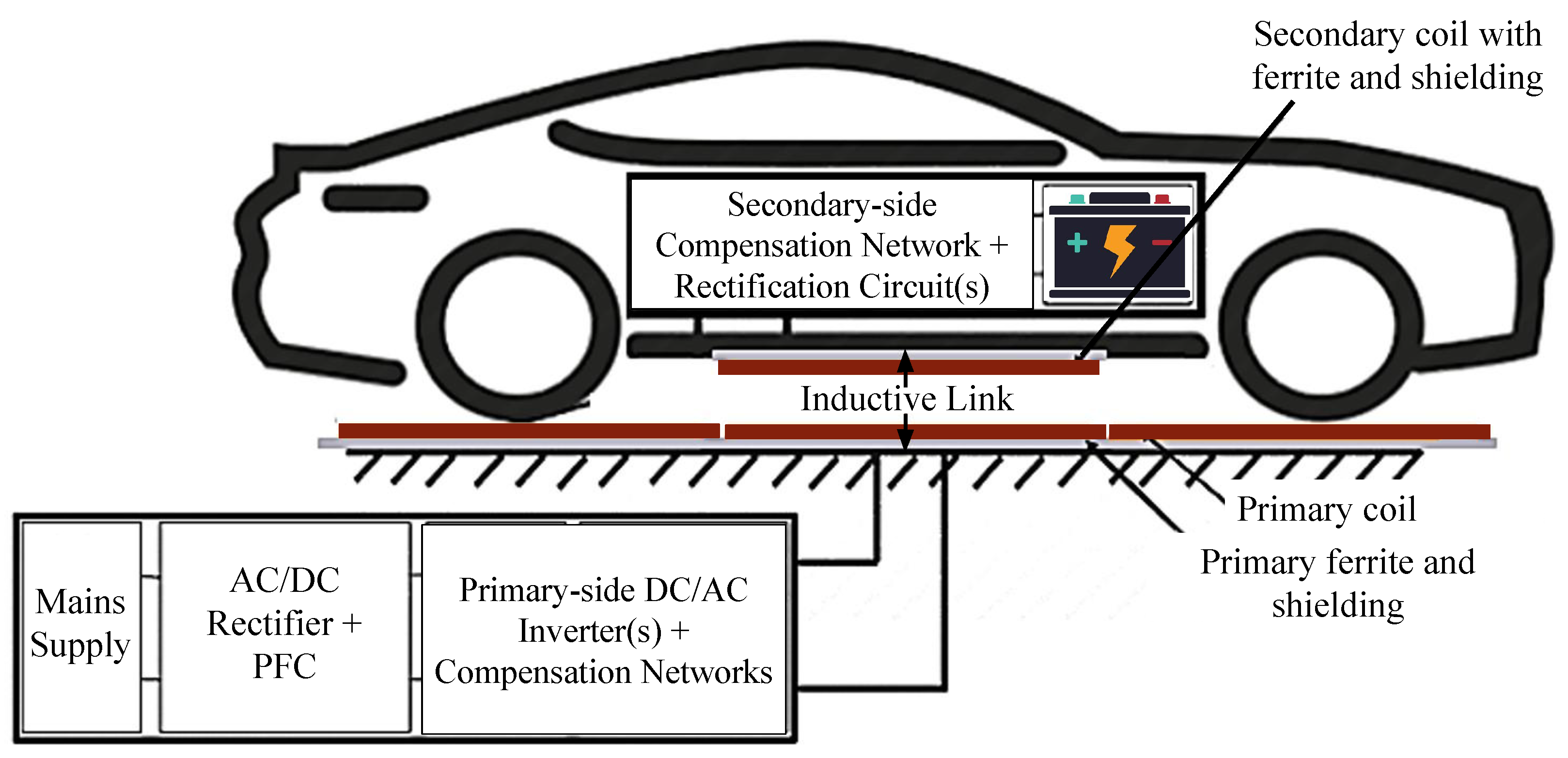
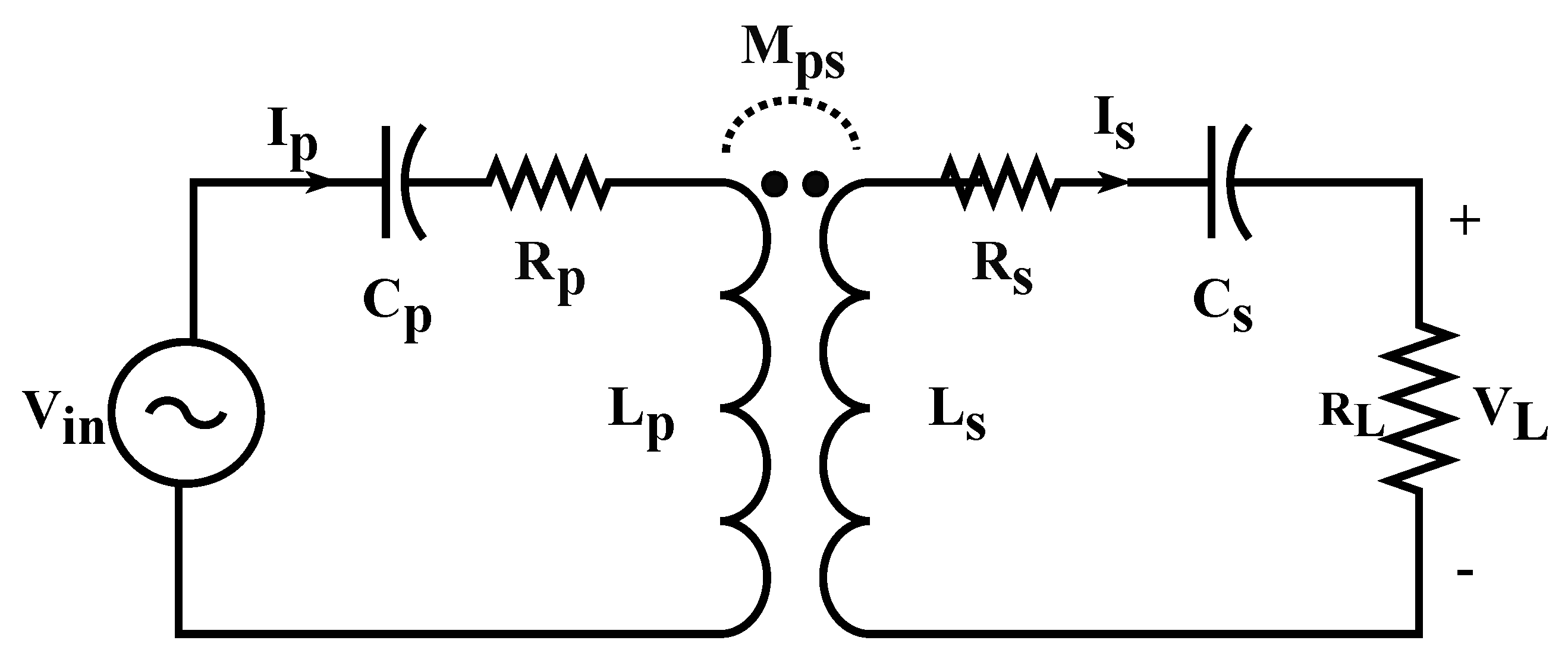
2. Inductive Link Modeling

A typical inductive link in a WEVC system consists of the charging coils, the ferrite core layer and the shielding layer. An outline of the inductive link is shown in Figure 2 using rectangular charging coils.
Each charging coil can be characterized using its self-inductance, L i , and its equivalent series resistance, ESR, R i , where the subscript i defines the side on which the coil is placed, such that i = p indicates the primary side and i = s indicates the secondary side. In order to evaluate the coupling performance of the primary and secondary charging pads at different alignment conditions, the uncompensated inductive link efficiency can be evaluated, independent of the other primary and secondary side circuits. This is expressed as [27],
η I L = k 2 Q p Q s 1 + 1 + k 2 Q p Q s 2 .
The link efficiency in Equation (1) depends on the coil quality factors, Q p and Q s , their self and mutual inductances and their coupling behavior. The coil quality factors are expressed as,
Q p = ω 0 L p R p ,
Q s = ω 0 L s R s ,
where ω 0 denotes the operating frequency of the power transfer system. During RIPT, mutual coupling takes place between the primary and secondary sides, which is characterized by the mutual inductance, M p s , and the coupling factor, k, expressed as,
k = M p s L p L s .
Based on the flux linkage between the primary and secondary charging pads, the coupling factor, k, takes values between 0 and 1, although for loosely-coupled systems such as WEVC systems, typical values of the coupling factor are between 0.1 and 0.4 depending on the coil geometries, vertical separation between the primary and secondary coils, and their lateral and longitudinal misalignments. From Equation (1), the factor k 2 Q p Q s can be used to evaluate the link performance. In particular, the Figure-of-Merit (FoM) used to evaluate the link performance in this work is defined as,
F o M = k 2 Q p Q s = k Q = ω 0 M p s R p R s .
The operating frequency of the inductive link for wireless EV chargers, ω 0 , is selected based on industry standards. The Society of Automotive Engineers (SAE) J2954 standard [28] identifies 85 kHz as the nominal operating frequency for static WEVC systems, with an acceptable tuning range of 79–90 kHz. As expected, the same secondary coil fitted at the bottom of the EV shall be utilized for static and dynamic charging. Hence, in order to ensure resonance operation and maximize the power transferred from the primary side to the secondary one, the primary and secondary coils need to be connected to a compensation network to enable resonance tuning at the desired operating frequency of 85 kHz.
Several compensation networks are reported in the literature [29,30], each of which demonstrates different wireless power transfer characteristics at different coupling and loading conditions. For dynamic wireless charging systems, a suitable compensation topology is one in which the secondary side current is independent of the voltage induced on the secondary side and only depends on the input AC voltage. This helps in minimizing fluctuations in the EV battery charging current during the motion of the EV [31] and can be achieved by both series-series (S-S) and inductor-capacitor-capacitor (LCC)-LCC compensation networks [11]. For simplicity, a S-S compensation topology is selected for this work, as shown in Figure 3.
In order to achieve resonance, values of the series capacitors, C p and C s , are tuned at ω 0 using the relationship,
ω 0 = 1 L p C p = 1 L s C s ,
at which the input impedance of the power transfer circuit in Figure 3 is purely real. The S-S compensated AC power transfer efficiency of the system at resonance is defined as,
η S S = ( ω 0 M p s ) 2 R L ( R s + R L ) ( R p ( R s + R L ) + ( ω 0 M p s ) 2 ) ,
where R L is the equivalent load resistance of the EV battery and the corresponding AC-DC rectification circuitry. This expression can be rewritten in terms of the kQ FoM in Equation (5) as,
η S S = k p s 2 Q p Q s R L R s 1 + R L R s 2 + k p s 2 Q p Q s 1 + R L R s .
Hence, according to Equations (1) and (8), increasing the inductive link efficiency can be achieved by increasing the coupling factor, k, and the respective coil quality factors, Q p and Q s . The coupling factor depends on the mutual and self-inductances of the two coils and is affected by the vertical distance between the two coils, their lateral and longitudinal misalignments and their geometric construction. The coil quality factors, on the other hand, are affected by ω 0 , the self inductances, and the ESRs of the primary and secondary coils, which are also dependent on the geometric construction of the coils. In this work, the expression in Equation (8) is used to determine the optimal FoM, to be used as a design criteria for the design of the inductive link.

3. Charging Coil Geometries

The magnetic flux distribution, and hence the mutual coupling, between the primary and secondary sides of the inductive link depends on the geometry of the primary and secondary coils, given identical ferrite and shielding layers. The coil geometries can be classified into:
  • Non-polarized geometries, such as circular and rectangular coils, in which the perpendicular component of the magnetic flux is responsible for the wireless power transfer process.
  • Polarized geometries, such as DD, DDQ and bipolar coils, in which the parallel component of the magnetic flux dominates and becomes responsible for the wireless power transfer process.
Rectangular, DD, DDQ and bipolar coil geometries are shown in Figure 4.
Different inductive link geometries are adopted in different WEVC system designs reported in the literature [23,24,25,26,32,33], and the coupling performance of the respective charging pads is used for the design of the remaining components of the respective static and dynamic WEVC systems shown in Figure 1. A qualitative comparison between the different geometries is outlined in [1,4], while quantitative comparisons are reported in [26,34,35]. The authors in [34] present a summary of the different characteristics of circular, DD and DDQ charging pads and use a set of simplifying assumptions to model each pad geometry on ANSYS Maxwell FEM simulator. Their work utilizes a single-turn coil with a wide wire diameter and a high excitation current to mimic the performance of a 20-turn coil with a low excitation current. While this simplified model may be acceptable for evaluating the coupling performance of the different coil geometries, it cannot be used to assess the coil quality factors and the k Q FoM, due to the differences in the self-inductances and the equivalent series resistances (ESRs) of a single-turn coil and those of a multi-turn coil. Accordingly, the impact of the inductive link design on the power transfer efficiency cannot be reliably assessed using this simplifying assumption.
The authors in [35], on the other hand, compare circular, DD, DDQ and bipolar coil geometries using FEM simulations on JMAG-Studio tool. The comparison is conducted based on the corresponding magnetic flux patterns, the coupling factors and the uncompensated output power received at the secondary side. Nevertheless, the effect of the different coil parameters is not acknowledged, since the comparison is conducted using coils with equal dimensions and equal numbers of turns. Coil parameter optimization is addressed in [26] by formulating a multi-objective optimization framework to optimize the coil dimensions for maximum power transfer efficiency, maximum misalignment tolerance and minimum stray fields exposure. However, the paper does not present details of the optimized design parameters but only provides conclusions on the performance of the different coil geometries for each of the optimization objectives.
Some of the key outcomes from the aforementioned studies are summarized as follows:
  • In non-polarized coil geometries, perpendicular magnetic field lines provide satisfactory coupling at perfect alignment conditions, and the coupling strength is impacted by the vertical air gap between the primary and secondary coils.
  • For effective coupling between circular charging coils, the vertical separation between the coils should be proportional to a quarter of the coil diameter [34]. Hence, significantly large circular coil diameters are required to improve the coupling performance in WEVC systems due to the large EV-to-ground clearance distance, i.e., the large air gap between the primary and secondary charging pads.
  • Parallel field patterns, on the other hand, are not as significantly affected by increasing the air gap, thereby they are expected to provide better coupling performance for large air gap applications such as WEVC systems, in comparison with non-polarized charging pads of equal dimensions.
  • For similar-sized charging pads, the flux path height of DD coils is double that of circular coils, which significantly reduces the flux leakage and enhances the coupling factor.
  • For symmetric DD-DD inductive link structures, as the secondary coil is displaced from the perfect alignment position, the flux linkage of the parallel fields experiences a significant degradation [35]. This motivates the addition of a quadrature coil, forming a DDQ charging pad, that utilizes parallel fields in perfect alignment conditions and benefits from the perpendicular field lines coupling with the quadrature coil during misalignments [26].
  • The key drawback of using DDQ coils is the added system weight, cost and complexity, due to the need to connect the DD and the quadrature portions of the charging pad to separate power management circuitry. This, on the receiver’s side, means that two separate compensation and rectification circuits are required to capture the maximum amount of transferred power during perfect alignment as well as when misalignments occur.
  • Bipolar charging pads leverage on the advantages of DDQ coils with 25–30% less copper in comparison with DDQ charging pads [36]. However, separate compensation, rectification and control circuits are also required for each coil constituting the bipolar charging pad.
Since DD coils consist of two equal-sized rectangular coils and are the underlying geometry for DDQ and bipolar coils, this work presents a systematic FEM-based design strategy for DD charging pads to determine the optimal parameters, namely number of turns and turn-to-turn spacing, to maximize the coupling performance of the charging pads given the available space constraints. The optimized DD coil design is fabricated and tested using an in-house prototype to validate the simulation results. Once simulation results are validated, an FEM-based comparison between rectangular, DD and DDQ coils is reported to provide recommendations on the most suitable and misalignment tolerant geometry for static and dynamic WEVC systems.

4. Design Strategy

With the aforementioned analysis in mind, the following procedure is followed to optimize the design of the DD charging coil.

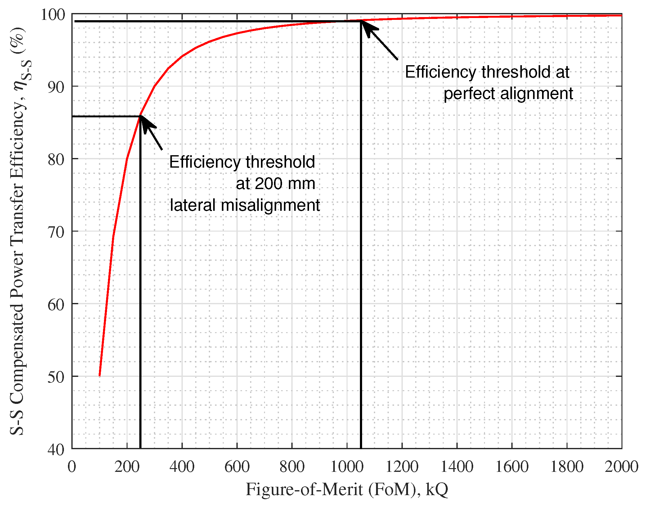
4.1. Definition of Efficiency Thresholds

The first step in the design of a high efficiency inductive link is to determine the minimum required k Q FoM to achieve the desired power transfer efficiency threshold at perfect alignment and at the desired misalignment tolerance. Based on existing WEVC system designs reported in the literature [9,10], as well as earlier work by the authors in [11], a practical efficiency threshold at perfect alignment is approximately 94 % , while at the desired lateral misalignment tolerance, the threshold can be reduced to 86 % . The theoretical relationship between the S-S compensated power transfer efficiency and the FoM in Equation (7) is plotted in Figure 5, using a load-to-secondary resistance ratio of R L R s = 10,000. Since this is a theoretical relationship, the perfect alignment efficiency threshold is selected to be a more stringent value of 99 % , as shown in Figure 5. Accordingly, the minimum required FoM to achieve the desired efficiency thresholds is selected to be the main IL design criteria for this work.

4.2. Definition of Constant Coil Parameters
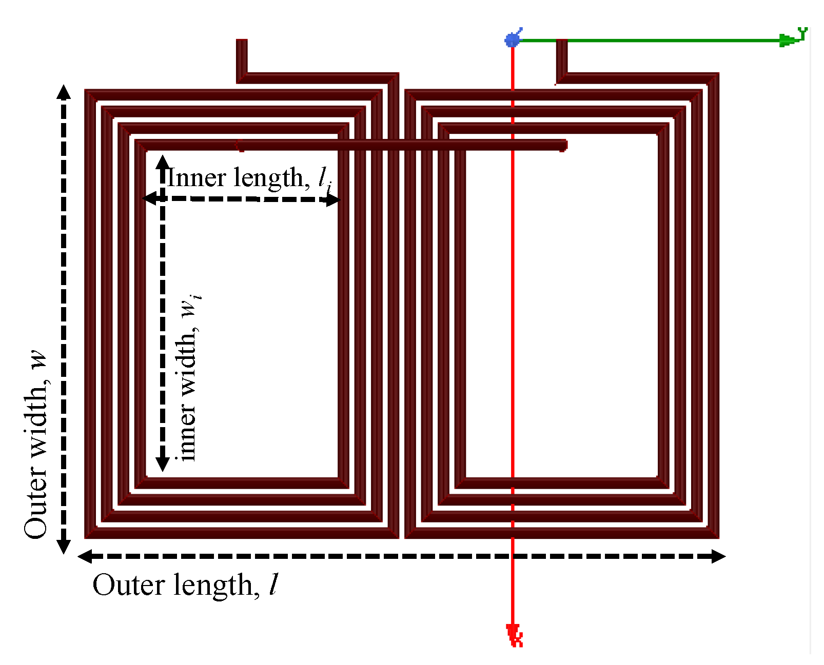
In order to ensure a fair comparison between the different coil geometries, and to increase the reliability of the obtained results while minimizing the number of variables under study, some of the coil parameters are held constant. These are detailed as follows:
  • Outer coil surface area, l × w : Acknowledging the space restrictions in the placement of the charging coils at the bottom of EVs, the outer coil area is determined given a set of considerations and is eliminated from the conducted parametric optimization process. According to [37], a reasonable secondary coil occupancy is around 480,000 mm 2 for a typical sedan EV, while the outer charging pad dimensions need to be larger to ensure effective shielding. In addition, according to [38], the optimal value of the width of a rectangular coil is three times the vertical separation between the primary and the secondary coils. The average vehicle-to-ground clearance of a typical EV is estimated to be ∼200 mm, based on which the outer coil width is selected to be 600 mm. Accordingly, for a total coil area of 480,000 mm 2 , the coil dimensions are selected to be 800 × 600 mm 2 .
  • Wire diameter, d: Stranded copper wires are utilized for all the simulations conducted in this work to reduce eddy current losses, effectively replicating the performance of Litz wires. According to [39], the current carrying capacity of a Litz wire is 4 A/mm 2 . Assuming the current through the coils is around 50 A for a 25 kW/500 V wireless EV charging system, the wire diameter is selected to 4 mm with a cross-sectional area of ∼12.5 mm 2 .
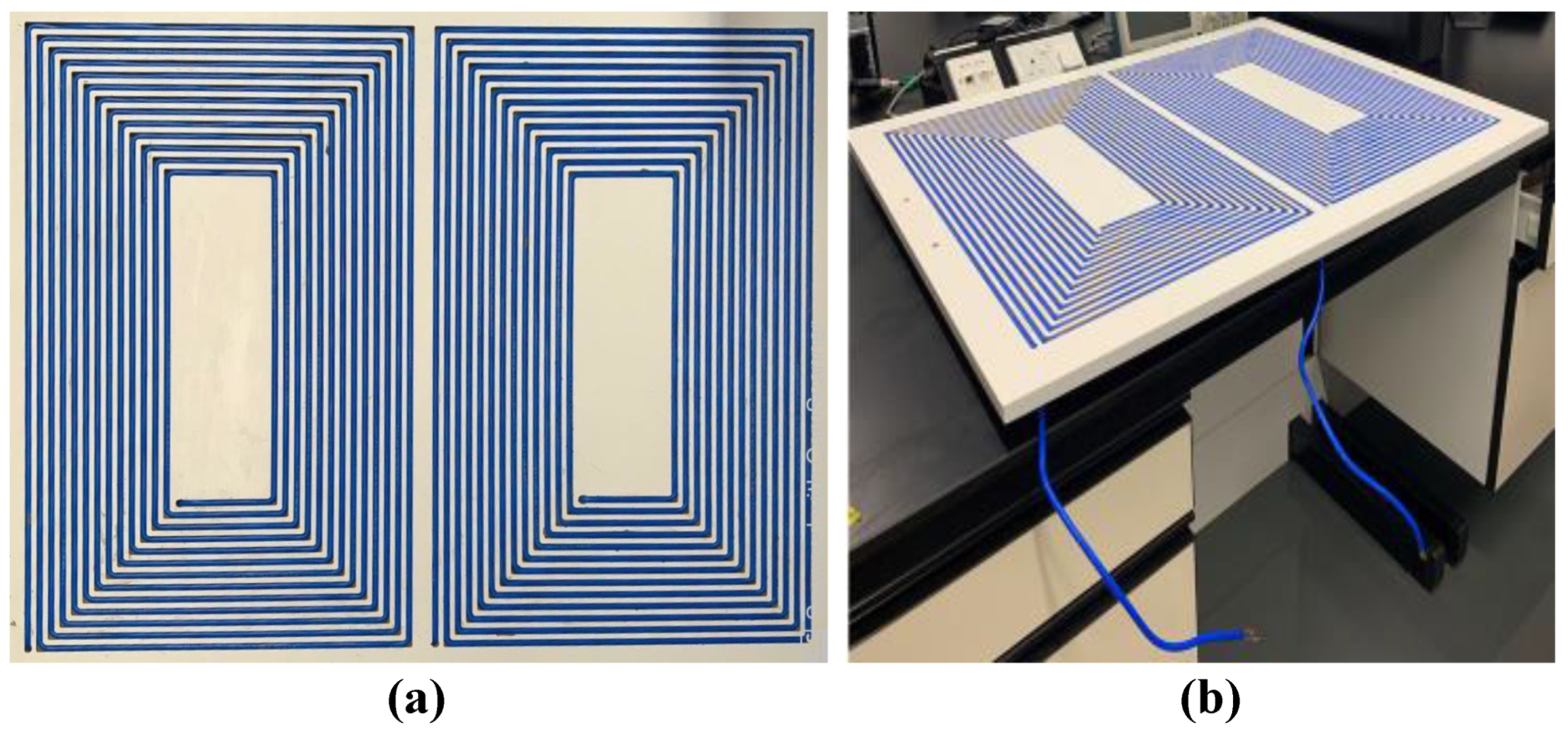
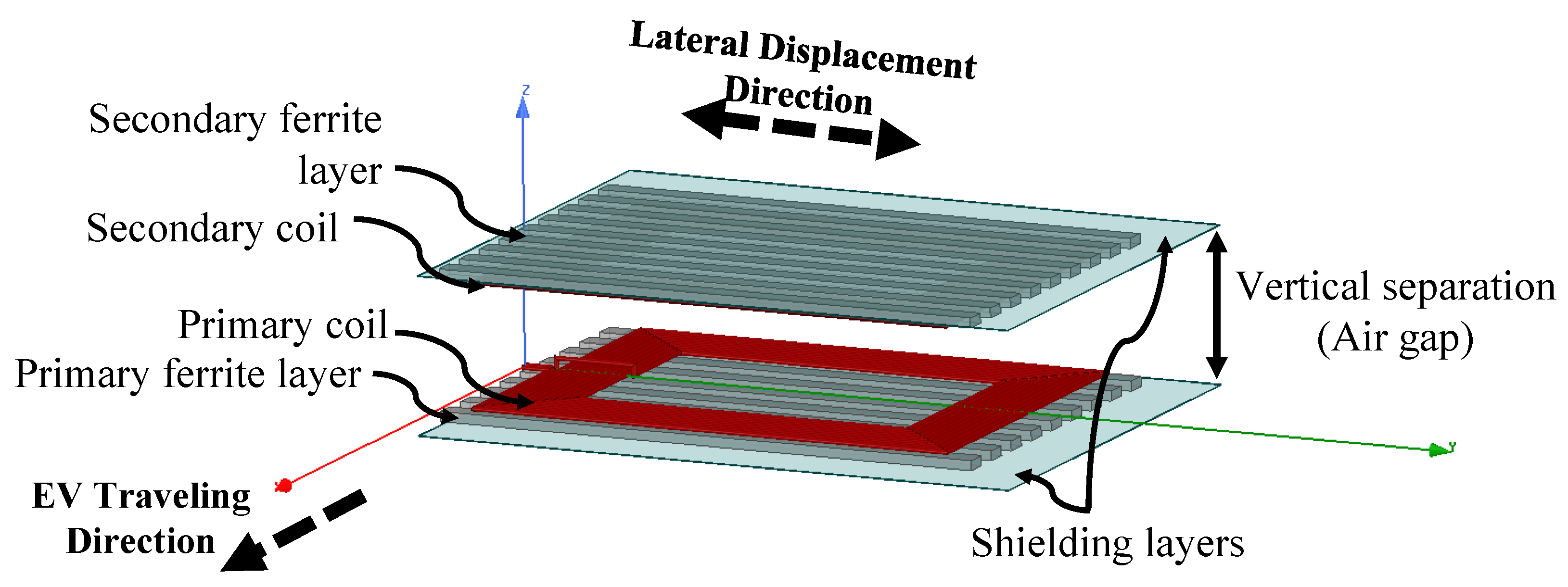
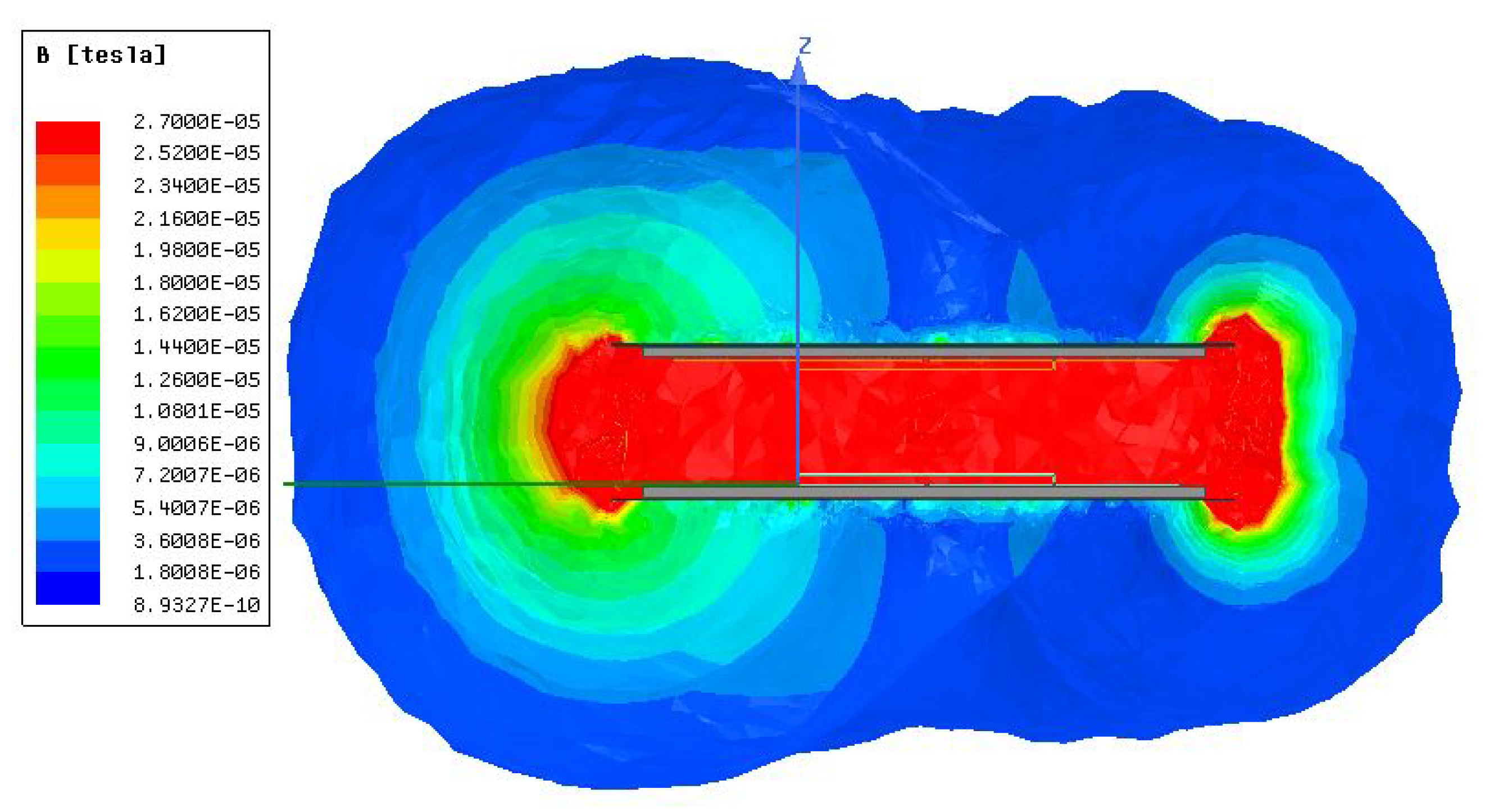
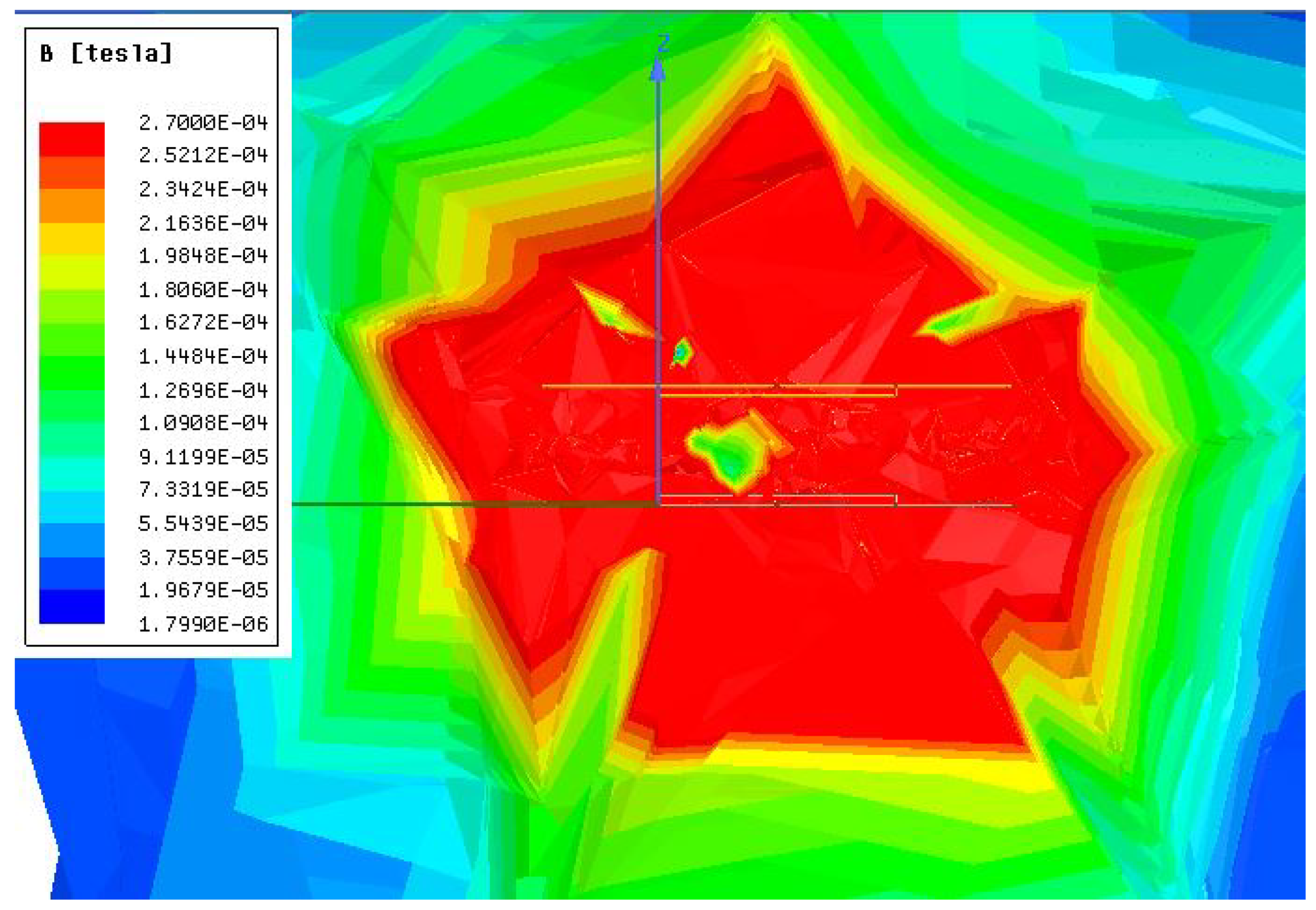
  • Ferrite and shielding layers: Since this work focuses on analyzing the performance of different coil geometries, identical ferrite and shielding layers are used for all the FEM simulations, as shown in Figure 4. The specifications of these layers are detailed in the authors’ earlier works in [11,23,40] and are summarized in Table 1.
The choice of the Aluminum shield thickness is such that it minimizes the field leakage beyond the area enclosed between the two coils. Accordingly, the thickness of the aluminum shield needs to be at least twice the skin depth of the aluminum alloy at the link operating frequency, ω 0 , to provide a minimum of 70 % reduction in field intensity surrounding the inductive link [41]. The skin depth of aluminum alloy is calculated using δ = 2 ω 0 μ 0 σ and is approximately equal to 0.3 mm. Nevertheless, to ensure effective shielding over a wide operating frequency range, the aluminum shield thickness is set to be six times the skin depth, i.e., 1.8 mm.

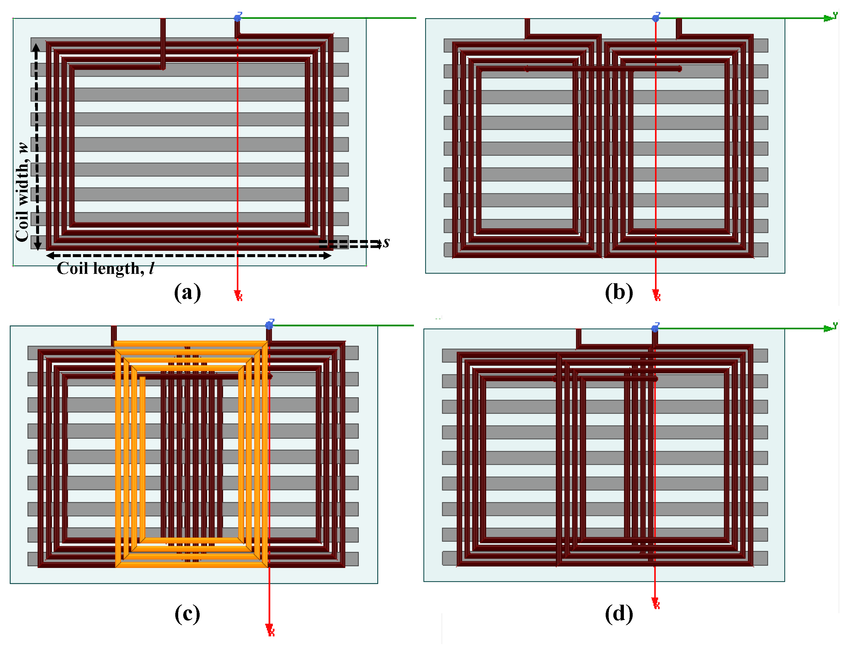
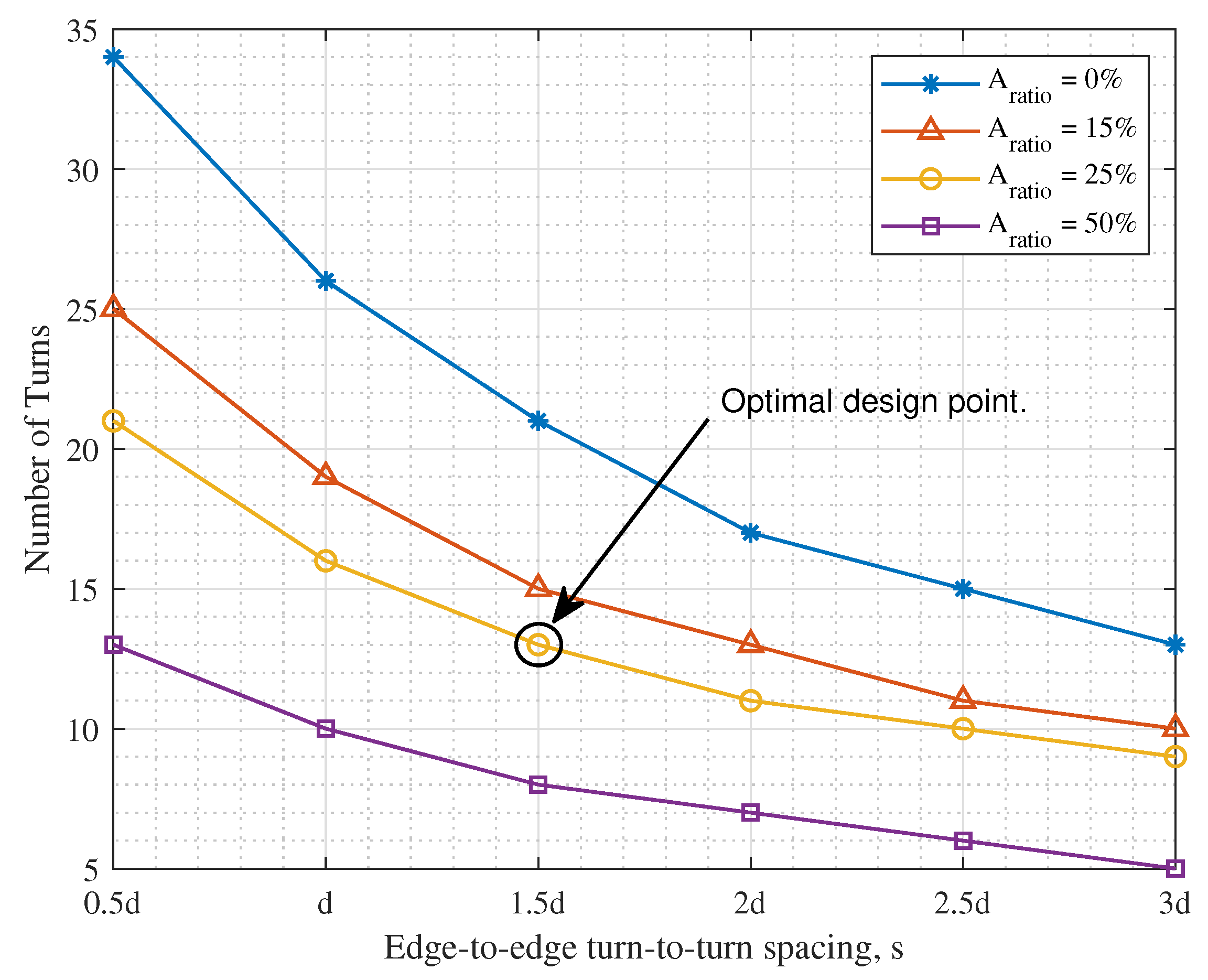
4.3. Identification of Design Variables

The variables in the coil design process under study are:
  • The number of turns of the coils, N.
  • The corresponding spacing between adjacent turns, s.
Since both variables impact the inner area of the planar coils under consideration, the inner-to-outer area ratio, A r a t i o , is initially utilized to study the joint effect of both variables on the inductive link. This is defined as the ratio between the area of the central gap of the coil and coil’s outer surface area, as shown in Figure 6.
Accordingly, A r a t i o is calculated as:
A r a t i o = 2 l i × w i l × w ,
assuming equal N and s for both rectangular sub-coils forming a single DD coil.

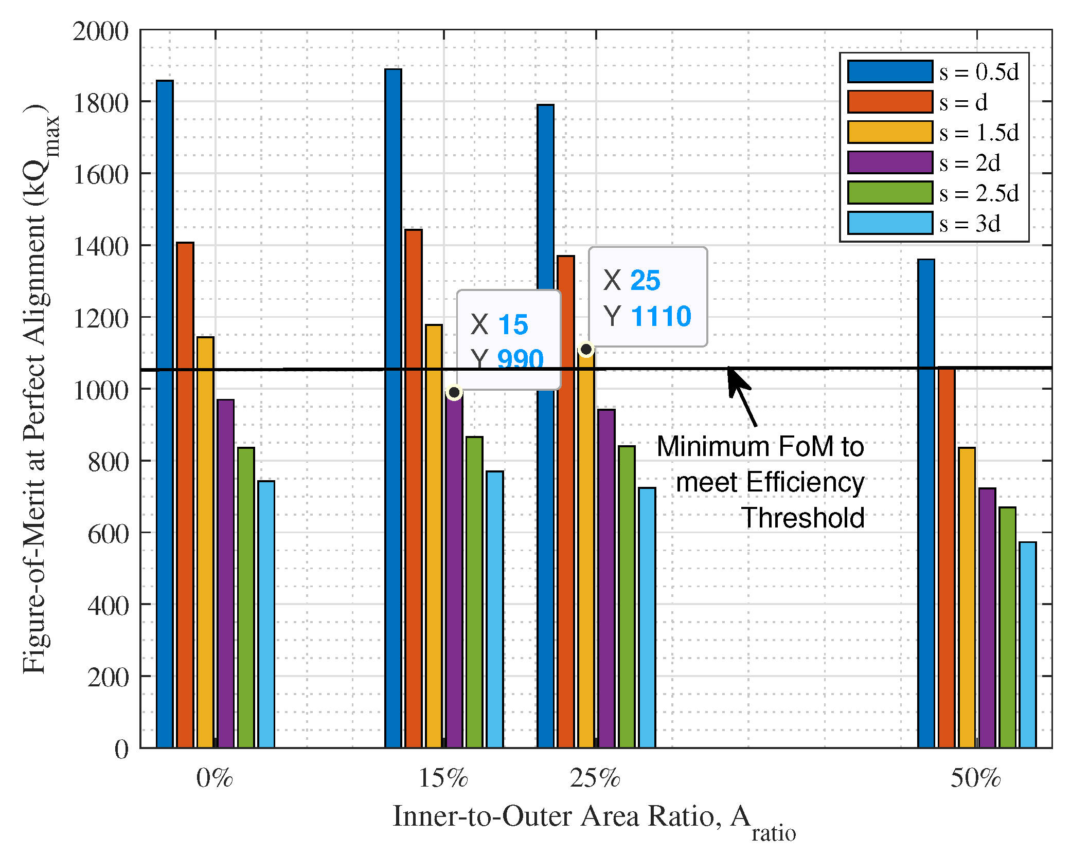
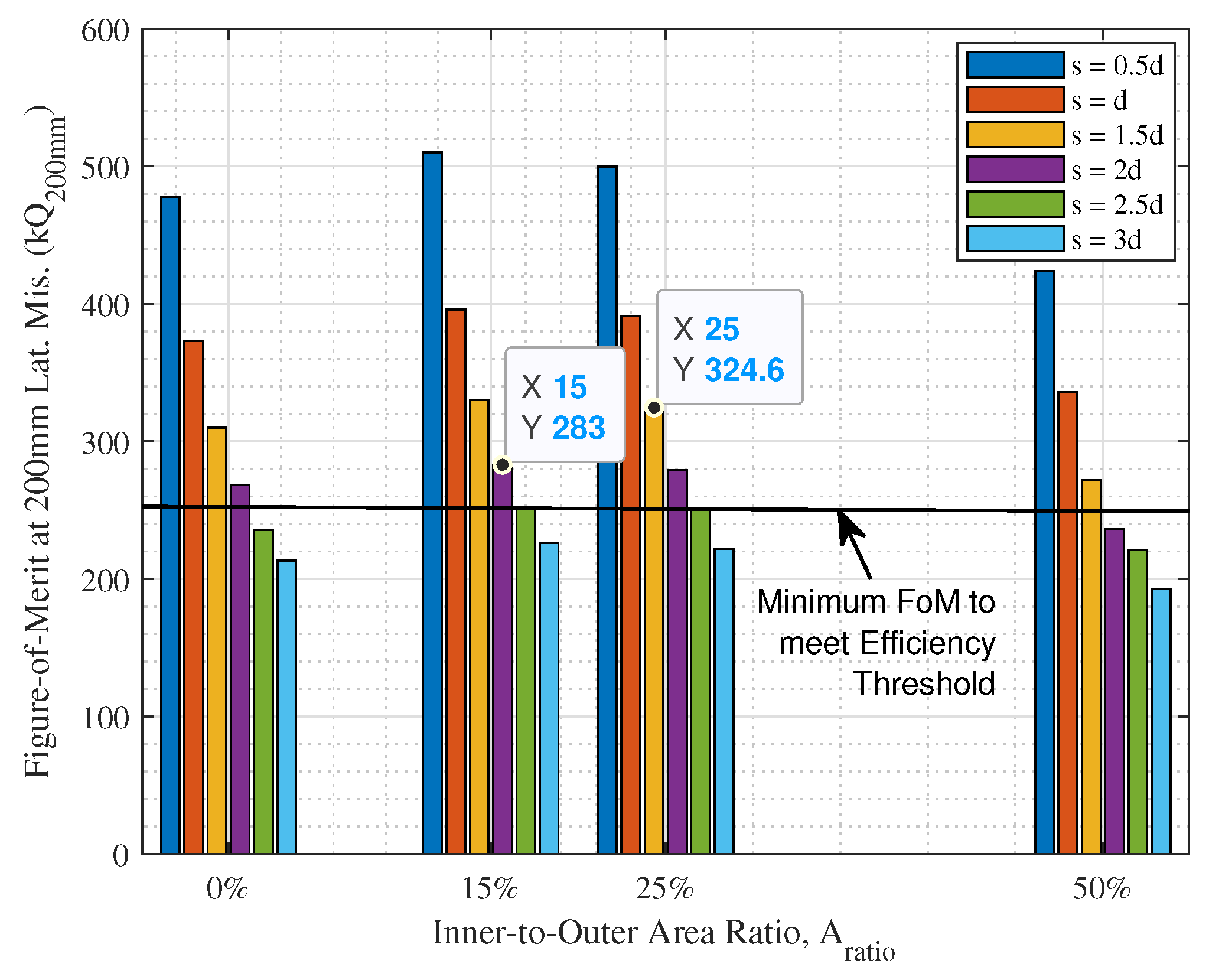
4.4. Parametric Optimization Using FEM Simulations

Acknowledging the aforementioned specifications, DD charging coils are constructed on ANSYS Maxwell FEM simulator in Eddy Current simulation mode with a 50 A excitation current for each coil, to represent a typical 25 kW, 500 V WEVC system. In order to assess the coupling performance of the DD coil at different A r a t i o , the FoM at perfect alignment and at ± 200 mm lateral misalignment is extracted from the FEM results, as shown in Figure 7 and Figure 8, respectively.
By studying Figure 7 and Figure 8, it is observed that the maximum A r a t i o required to simultaneously satisfy the efficiency threshold at both perfect alignment and ± 200 mm lateral misalignment as shown in Figure 5, is 25 % , using an edge-to-edge turn-to-turn spacing of s = 1.5 d , where d is the wire diameter. The corresponding number of turns is hence determined from the relationship between N, s and A r a t i o to be 13 turns, as shown in Figure 9.
Accordingly, the geometric specifications of the optimum DD charging coil design are summarized in Table 2.

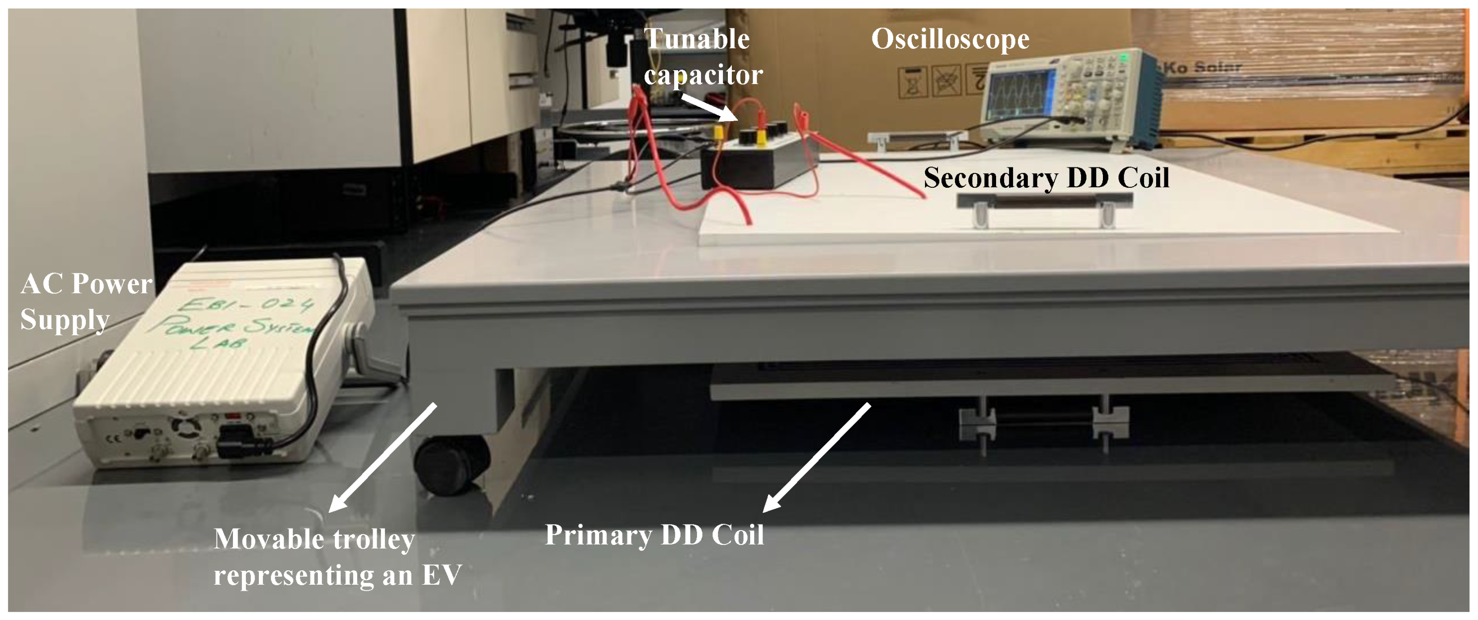
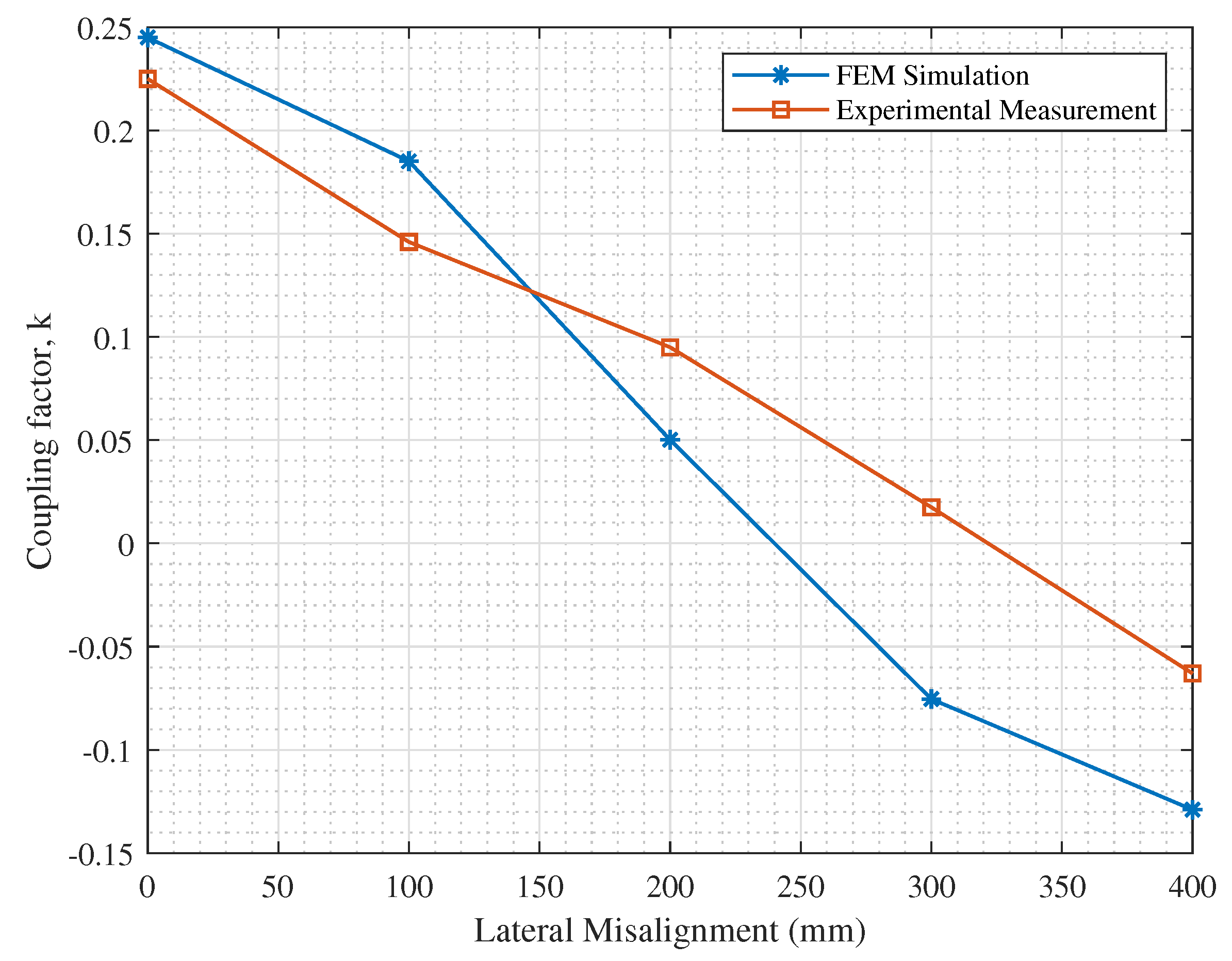
5. Simulation Results and Experimental Verification

Using the optimal DD coil design specifications in Table 2, the shielding effect is first verified using FEM simulations to ensure abidance by the maximum permissable exposure limits described earlier. FEM simulations are conducted with and without the ferrite and shielding layers specified in Table 1, and the corresponding magnetic field intensity plots are reported in Figure 10 and Figure 11, respectively.
As observed in Figure 10, the magnetic field intensity surrounding the inductive link is within the 27 μT maximum exposure limit when ferrite and shielding layers are added following the specifications in Table 1. In contrast, Figure 11 demonstrates that, without ferrite and shielding, extensive field leakage is observed in the area surrounding the inductive link, and the field pattern is randomly dispersed. This emphasizes the importance of adding these layers to ensure safety of the surrounding human beings in full scale implementations of the WEVC system.
Nevertheless, due to cost restrictions and the unavailability of the ferrite core or the Aluminum shielding in the local market, these two layers are not fabricated for the coil prototypes to be tested. Hence, two identical coil prototypes following the optimum DD coil design in Section 4 are fabricated using 4 mm diameter stranded copper wires with the dimensions in Table 2, as shown in Figure 12.
A movable trolley is constructed to represent an EV holding the secondary coil, and the primary coil is placed on the ground connected to an AC voltage supply. A tunable capacitor bank is connected in series to each coil to further tune the capacitance values to resonate the circuit at the desired operating frequency, and the secondary coil is connected to an oscilloscope to observe the output voltage on the secondary side. This testing setup is shown in Figure 13 and the list of equipment is described in Table 3.
Accordingly, to guarantee the safety of the experimenters, the input AC voltage used for the experimental setup in Figure 13 is set to be 1–2 orders of magnitude lower than the 500 V used in the simulations, to ensure low excitation currents and low surrounding field intensity, while enabling the experimenters to verify the coupling performance of the proposed inductive link design. Furthermore, FEM simulations are repeated for the optimized 13-turn DD coil design with no ferrite and shielding layers, and the results are compared to those obtained from the experimental prototype. Besides, since the available testing equipment can only operate at 100 kHz, this set of FEM simulations is conducted at 100 kHz to allow a fair comparison between the simulation results and the experimental measurements.
The self-inductances and ESRs of the fabricated primary and secondary coils are first measured using an LCR meter operating at 100 kHz and are compared to the simulation results as shown in Table 4.
As observed in Table 4, the coil parameters of the two fabricated coil prototypes are slightly different, which is mainly due to imperfections in the fabrication process. In comparison with the FEM simulation results, a tolerable average error of 15 % is observed in the self inductance values. However, the ESRs of the coil prototypes are 10 times higher than the simulated value, which significantly degrades the coil quality factor. This is mainly due to the nature of the copper wires used for the coil construction. This is because the simulated Litz wires are characterized by relatively lower AC and DC resistances in comparison with the stranded copper wires used in the fabrication of the coil prototypes. Nevertheless, using the measured self-inductance values in Table 4, the compensation capacitor values are calculated using Equation (6) at ω 0 = 100 kHz to ensure resonance operation.
The mutual coupling between the primary and secondary coils in the experimental prototype is evaluated using the voltage gain method, by measuring the voltage gain between the received AC voltage at the secondary side, V L , across the load resistance, R L , and the input AC voltage at the primary side, V i n . For S-S compensated circuits, the voltage gain relationship is expressed as,
V L V i n = ω 0 M p s R L R p ( R s + R L ) + ω 0 2 M p s 2 .
Due to the major differences in the coil quality factors reported in Table 4, only the coupling factor, k is used to verify the simulation results, as shown in Figure 14.
By observing Figure 14, a satisfactory agreement is observed between the experimental and simulation results of k at perfect alignment and at misalignments up to ≈200 mm. At further misalignments, imprecisions in distance measurements by the experimenters may have caused the increasing difference in values as misalignment increases. Nevertheless, the results in Figure 14 confirm the reliability of the simulation setup and the design procedure followed in this work up to the desired lateral misalignment tolerance of ± 200 mm. Accordingly, FEM simulations are then utilized to compare between rectangular, DD and DDQ coils.

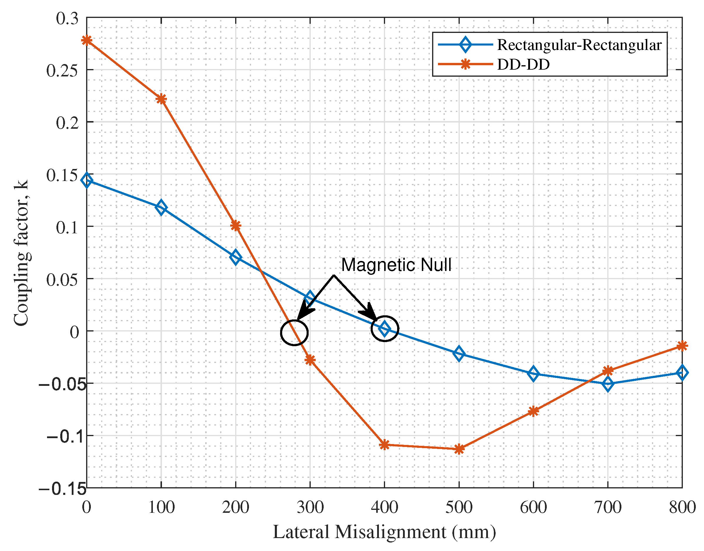
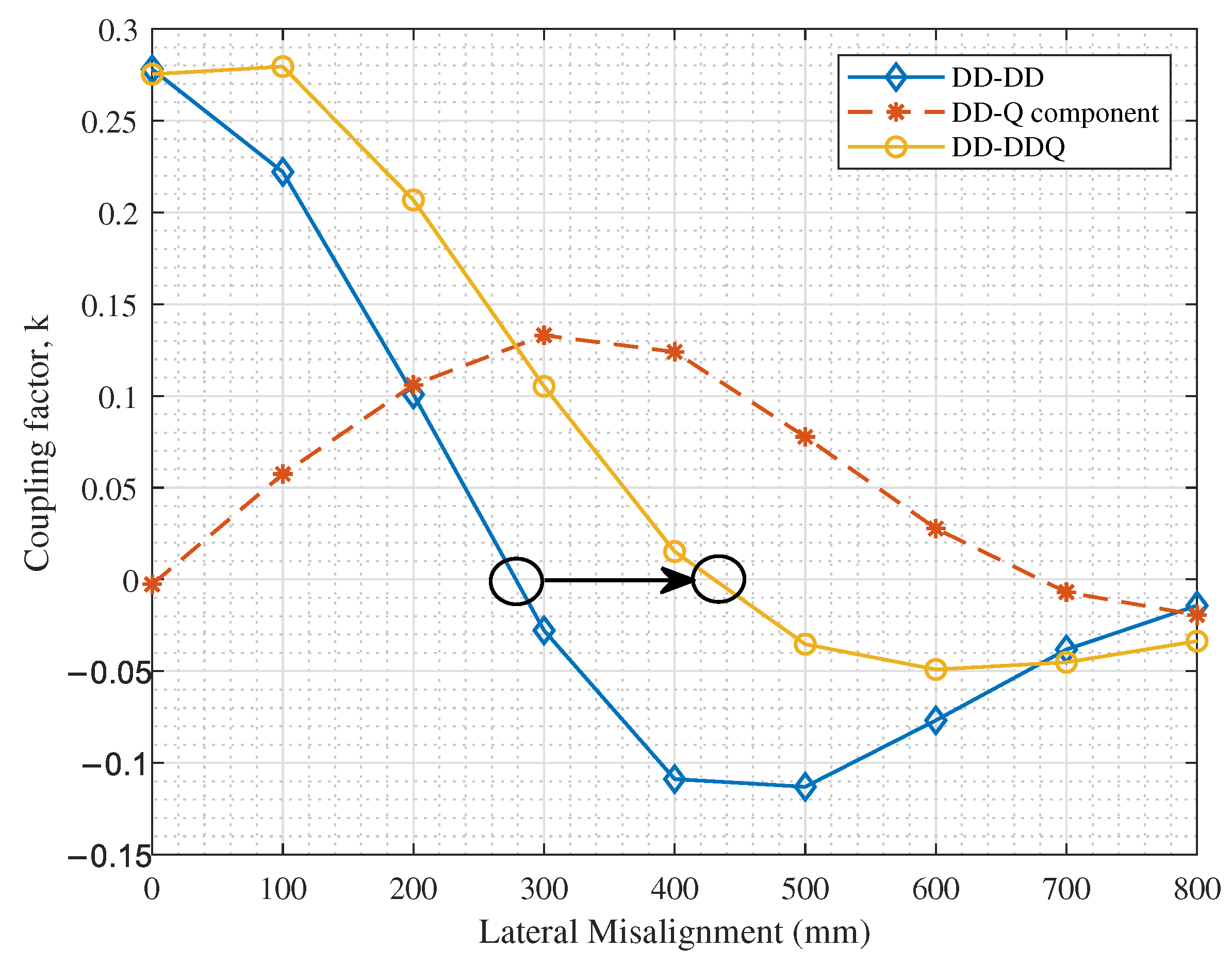
6. Rectangular, DD and DDQ Charging Coils

Upon validating the simulation model with the experimental prototype of the DD coil, an FEM-based comparison between rectangular, DD and DDQ coils is conducted. The same ferrite and shielding specifications are used as in Table 1. However, in order to reduce the simulation time and resource utilization, only 4-turn coils are simulated for this comparative study. The remaining coil specifications are the same as those in Table 2.
While the FoM is utilized for the design of the different coil parameters to evaluate their overall impact on the self and mutual inductances of the coils and their ESRs, the coupling factor is a better decision variable for the comparison between different coil geometries of similar parameters. This is because the coupling factor captures the magnetic field patterns with its positive and negative polarity values, which is otherwise not possible with the FoM which squares the k value. Accordingly, the coupling factor is used to compare the performance of the different coil geometries in this section.
Two performance criteria are used to evaluate the misalignment tolerance of the different inductive link geometries under consideration:
  • The coupling performance at 200 mm lateral misalignment.
  • The magnetic null point.
The magnetic null point is a point to the left and right of the perfect alignment position, at which the magnetic fields completely cancel out and the coupling factor is dropped to zero. In this work, assuming symmetric coil structures about the vehicle’s axis, only the right-side magnetic null point is considered.
Accordingly, the coupling performance of symmetric rectangular-rectangular (D-D) and DD-DD inductive links is shown in Figure 15.
As observed in Figure 15, DD coils have a superior coupling performance at perfect alignment and at 200 mm lateral misalignment. However, due to the degradation in the parallel magnetic field pattern as explained earlier, the magnetic null occurs at a smaller lateral misalignment value for DD coils in comparison with rectangular coils; at <300 mm for DD-DD coils and at 400 mm for rectangular coils. Hence, in order to leverage on the advantages of the DD coils while extending its positive coupling range, a quadrature coil is added on the secondary side, as reported in [26], to improve the misalignment tolerance of the inductive link without adding to the complexity of the primary side circuitry. The effect of adding the quadrature coil is demonstrated in Figure 16.
As observed in Figure 16, the added quadrature coil couples with the primary coil as the secondary charging pad is laterally displaced. Accordingly, the effective coupling performance of the DD-DDQ inductive link shows a significant improvement in the positive coupling range, by shifting the magnetic null from <300 mm to ∼430 mm, while preserving the satisfactory performance at perfect alignment. Nevertheless, it must be highlighted that to translate this coupling pattern into a satisfactory received power at lateral misalignments beyond 200 mm, a separate compensation and rectification circuit needs to be connected to the quadrature coil, in addition to that connected to the underlying DD coil. Collectively, the output power from both circuits is added and used to charge the EV battery. Nevertheless, the design of these circuits is not included in the scope of this paper.

7. Conclusions

This work presents details of the design of a DD charging pad to be used as the inductive link in wireless EV charging systems. The proposed design is based on defining the minimum FoM of the charging pads required to achieve acceptable power transfer efficiencies at perfect alignment and at a desired lateral misalignment tolerance. Using FoM as the design criteria, a parametric optimization of the number of turns and turn-to-turn spacing of the DD coil is conducted using FEM simulations. The performance of the electromagnetic shielding layers is also studied using FEM simulations. The proposed optimal design is verified against an experimental prototype and the reliability of the simulation results is confirmed, within limits of experimental inaccuracies.
Accordingly, a comparison between the coupling performance of rectangular, DD and DDQ charging pads is performed and assessed based on the lateral misalignment tolerance and the occurrence of the magnetic null point. Results reveal that using a DDQ charging pad for the secondary coil with a DD primary coil provides extended lateral misalignment tolerance with higher coupling at perfect alignments in contrast with D-D and DD-DD inductive links. Nevertheless, these advantages come at an increased coil weight, cost and power management circuit complexity. Accordingly, a DD-DDQ inductive link is recommended for dynamic WEVC systems to maximize the received power on the secondary side despite increased lateral misalignments. For static WEVC systems, on the other hand, DD-DD inductive links are considered sufficient, provided that the lateral misalignments maintain a positive coupling level.

Author Contributions

Conceptualization, E.E., M.H., A.O. and H.K.; methodology, E.E.; software, H.K.; validation, M.H. and A.O.; formal analysis, E.E.; investigation, E.E. and H.K.; resources, M.H. and A.O.; data curation, E.E.; writing—original draft preparation, E.E.; writing—review and editing, M.H. and A.O.; visualization, E.E., M.H., A.O. and H.K.; supervision, M.H. and A.O.; project administration, M.H. and A.O.; funding acquisition, M.H. All authors have read and agreed to the published version of the manuscript.

Funding

This work is jointly supported by the American University of Sharjah through SCRI grant number SCRI 18-CEN-10 and by Sharjah Research Academy (SRA), Sharjah, United Arab Emirates.

Conflicts of Interest

The authors declare no conflict of interest.

References

  1. Patil, D.; McDonough, M.K.; Miller, J.M.; Fahimi, B.; Balsara, P.T. Wireless Power Transfer for Vehicular Applications: Overview and Challenges. IEEE Trans. Transp. Electrif. 2018, 4, 3–37. [Google Scholar] [CrossRef]
  2. Jayakumar, A. Review of prospects for adoption of fuel cell electric vehicles in New Zealand. IET Electr. Syst. Transp. 2017, 7, 259–266. [Google Scholar] [CrossRef]
  3. Wu, H.H.; Gilchrist, A.; Sealy, K.D.; Bronson, D. A High Efficiency 5 kW Inductive Charger for EVs Using Dual Side Control. IEEE Trans. Ind. Inform. 2012, 8, 585–595. [Google Scholar] [CrossRef] [Green Version]
  4. Ahmad, A.; Alam, M.S.; Chabaan, R. A Comprehensive Review of Wireless Charging Technologies for Electric Vehicles. IEEE Trans. Transp. Electrif. 2018, 4, 38–63. [Google Scholar] [CrossRef]
  5. IEEE Approved Draft Standard for Safety Levels with Respect to Human Exposure to Electric, Magnetic and Electromagnetic Fields, 0 Hz to 300 GHz; IEEE PC95.1/D3.5, October 2018; IEEE: Piscataway, NJ, USA, 2019; pp. 1–312.
  6. ICNIRP. Guidelines for Limiting Exposure to Time-Varying Electric and Magnetic Fields (1 Hz–100 kHz). Health Phys. 2010, 99, 818–836. [Google Scholar] [CrossRef] [PubMed]
  7. Tavakoli, R.; Pantic, Z. Analysis, Design, and Demonstration of a 25-kW Dynamic Wireless Charging System for Roadway Electric Vehicles. IEEE J. Emerg. Sel. Top. Power Electron. 2018, 6, 1378–1393. [Google Scholar] [CrossRef]
  8. Shin, J.; Shin, S.; Kim, Y.; Ahn, S.; Lee, S.; Jung, G.; Jeon, S.; Cho, D. Design and Implementation of Shaped Magnetic-Resonance-Based Wireless Power Transfer System for Roadway-Powered Moving Electric Vehicles. IEEE Trans. Ind. Electron. 2014, 61, 1179–1192. [Google Scholar] [CrossRef]
  9. Feng, H.; Cai, T.; Duan, S.; Zhao, J.; Zhang, X.; Chen, C. An LCC-Compensated Resonant Converter Optimized for Robust Reaction to Large Coupling Variation in Dynamic Wireless Power Transfer. IEEE Trans. Ind. Electron. 2016, 63, 6591–6601. [Google Scholar] [CrossRef]
  10. Zhu, Q.; Wang, L.; Guo, Y.; Liao, C.; Li, F. Applying LCC Compensation Network to Dynamic Wireless EV Charging System. IEEE Trans. Ind. Electron. 2016, 63, 6557–6567. [Google Scholar] [CrossRef]
  11. ElGhanam, E.; Hassan, M.; Osman, A. Design of a High Power, LCC-Compensated, Dynamic, Wireless Electric Vehicle Charging System with Improved Misalignment Tolerance. Energies 2021, 14, 885. [Google Scholar] [CrossRef]
  12. Jeong, S.; Jang, Y.J.; Kum, D. Economic Analysis of the Dynamic Charging Electric Vehicle. IEEE Trans. Power Electron. 2015, 30, 6368–6377. [Google Scholar] [CrossRef]
  13. Vaidehi, S.; Dhar, S.; Jayakumar, A.; Lavanya, R.; Dinesh Kumar, M. Techno-economic assessment of various motors for three-wheeler E-auto rickshaw: From Indian context. Mater. Today Proc. 2021. [Google Scholar] [CrossRef]
  14. Green, P.; Cullinane, B.; Zylstra, B.; Smith, D. Typical Values for Driving Performance with Emphasis on the Standard Deviation of Lane Position: A Summary of the Literature. In Safety Vehicles Using Adaptive Interface Technology(Task 3A); U.S. Department of Transportation: Cambridge, MA, USA, 2004. [Google Scholar]
  15. Ramezani, A.; Farhangi, S.; Iman-Eini, H.; Farhangi, B.; Rahimi, R.; Moradi, G.R. Optimized LCC-Series Compensated Resonant Network for Stationary Wireless EV Chargers. IEEE Trans. Ind. Electron. 2019, 66, 2756–2765. [Google Scholar] [CrossRef]
  16. Lassioui, A.; Fadil, H.E.; Rachid, A.; Belhaj, F.Z.; Tarkany, O.; Bajit, A. Characterestics Analysis of Wireless Power Transfer System for Electric Vehicle Charging Applications. In Proceedings of the 2018 International Symposium on Advanced Electrical and Communication Technologies (ISAECT), Rabat, Morocco, 21–23 November 2018; pp. 1–6. [Google Scholar] [CrossRef]
  17. Tan, L.; Zhao, W.; Ju, M.; Liu, H.; Huang, X. Research on an EV Dynamic Wireless Charging Control Method Adapting to Speed Change. Energies 2019, 12, 2214. [Google Scholar] [CrossRef] [Green Version]
  18. Zhang, W.; Wong, S.; Tse, C.K.; Chen, Q. An Optimized Track Length in Roadway Inductive Power Transfer Systems. IEEE J. Emerg. Sel. Top. Power Electron. 2014, 2, 598–608. [Google Scholar] [CrossRef]
  19. Liang, X.; Chowdhury, M.S.A. Emerging Wireless Charging Systems for Electric Vehicles - Achieving High Power Transfer Efficiency: A Review. In Proceedings of the 2018 IEEE Industry Applications Society Annual Meeting (IAS), Portland, OR, USA, 23–27 September 2018; pp. 1–14. [Google Scholar] [CrossRef]
  20. Liu, H.; Tan, L.; Huang, X.; Zhang, M.; Zhang, Z.; Li, J. Power Stabilization based on Switching Control of Segmented Transmitting Coils for Multi Loads in Static-Dynamic Hybrid Wireless Charging System at Traffic Lights. Energies 2019, 12, 607. [Google Scholar] [CrossRef] [Green Version]
  21. Mazharov, N.; Hristov, S.; Dichev, D.; Zhelezarov, I. Some Problems of Dynamic Contactless Charging of Electric Vehicles. Acta Polytech. Hung. 2017, 14, 7–26. [Google Scholar] [CrossRef]
  22. Ahmad, A.; Alam, M.S.; Mohamed, A.A.S. Design and Interoperability Analysis of Quadruple Pad Structure for Electric Vehicle Wireless Charging Application. IEEE Trans. Transp. Electrif. 2019, 5, 934–945. [Google Scholar] [CrossRef]
  23. ElGhanam, E.A.; Hassan, M.S.; Osman, A. Design and Finite Element Modeling of The Inductive Link in Wireless Electric Vehicle Charging Systems. In Proceedings of the 2020 IEEE Transportation Electrification Conference Expo (ITEC), Chicago, IL, USA, 23–26 June 2020; pp. 389–394. [Google Scholar]
  24. Ongayo, D.; Hanif, M. Comparison of Circular and Rectangular Coil Transformer Parameters for Wireless Power Transfer based on Finite Element Analysis. In Proceedings of the 2015 IEEE 13th Brazilian Power Electronics Conference and 1st Southern Power Electronics Conference (COBEP/SPEC), Fortaleza, Brazil, 29 November–2 December 2015; pp. 1–6. [Google Scholar] [CrossRef]
  25. Bosshard, R.; Iruretagoyena, U.; Kolar, J.W. Comprehensive Evaluation of Rectangular and Double-D Coil Geometry for 50 kW/85 kHz IPT System. IEEE J. Emerg. Sel. Top. Power Electron. 2016, 4, 1406–1415. [Google Scholar] [CrossRef]
  26. Bandyopadhyay, S.; Venugopal, P.; Dong, J.; Bauer, P. Comparison of Magnetic Couplers for IPT-Based EV Charging Using Multi-Objective Optimization. IEEE Trans. Veh. Technol. 2019, 68, 5416–5429. [Google Scholar] [CrossRef]
  27. Zargham, M.; Gulak, P.G. Maximum Achievable Efficiency in Near-Field Coupled Power-Transfer Systems. IEEE Trans. Biomed. Circ. Syst. 2012, 6, 228–245. [Google Scholar] [CrossRef] [PubMed]
  28. Wireless Power Transfer for Light-Duty Plug-in/Electric Vehicles and Alignment Methodology; SAE J2954, April 2019; SAE International: Warrendale, PA, USA, 2019.
  29. Lu, J.; Zhu, G.; Wang, H.; Lu, F.; Jiang, J.; Mi, C.C. Sensitivity Analysis of Inductive Power Transfer Systems with Voltage-Fed Compensation Topologies. IEEE Trans. Veh. Technol. 2019, 68, 4502–4513. [Google Scholar] [CrossRef]
  30. Abou Houran, M.; Yang, X.; Chen, W. Magnetically Coupled Resonance WPT: Review of Compensation Topologies, Resonator Structures with Misalignment, and EMI Diagnostics. Electronics 2018, 7, 296. [Google Scholar] [CrossRef] [Green Version]
  31. Li, W.; Zhao, H.; Deng, J.; Li, S.; Mi, C.C. Comparison Study on SS and Double-Sided LCC Compensation Topologies for EV/PHEV Wireless Chargers. IEEE Trans. Veh. Technol. 2016, 65, 4429–4439. [Google Scholar] [CrossRef]
  32. Lin, F.Y.; Covic, G.A.; Boys, J.T. Evaluation of Magnetic Pad Sizes and Topologies for Electric Vehicle Charging. IEEE Trans. Power Electron. 2015, 30, 6391–6407. [Google Scholar] [CrossRef]
  33. Liu, Y.; Mai, R.; Yue, P.; Li, Y.; He, Z. Efficiency optimization for wireless dynamic charging system with overlapped DD coil arrays. In Proceedings of the 2017 IEEE Applied Power Electronics Conference and Exposition (APEC), Tampa, FL, USA, 26–30 March 2017; pp. 1439–1442. [Google Scholar] [CrossRef]
  34. Marco, D.; Dolara, A.; Longo, M.; Yaici, W. Design and Performance Analysis of Pads for Dynamic Wireless Charging of EVs using the Finite Element Method. Energies 2019, 12, 4139. [Google Scholar] [CrossRef] [Green Version]
  35. Zaheer, A.; Hao, H.; Covic, G.A.; Kacprzak, D. Investigation of Multiple Decoupled Coil Primary Pad Topologies in Lumped IPT Systems for Interoperable Electric Vehicle Charging. IEEE Trans. Power Electron. 2015, 30, 1937–1955. [Google Scholar] [CrossRef]
  36. Lin, F.Y.; Kim, S.; Covic, G.A.; Boys, J.T. Effective Coupling Factors for Series and Parallel Tuned Secondaries in IPT Systems Using Bipolar Primary Pads. IEEE Trans. Transp. Electrif. 2017, 3, 434–444. [Google Scholar] [CrossRef]
  37. Nguyen, T.; Li, S.; Li, W.; Mi, C.C. Feasibility Study on Bipolar Pads for Efficient Wireless Power Chargers. In Proceedings of the 2014 IEEE Applied Power Electronics Conference and Exposition—APEC 2014, Fort Worth, TX, USA, 16–20 March 2014; pp. 1676–1682. [Google Scholar] [CrossRef]
  38. Sallan, J.; Villa, J.L.; Llombart, A.; Sanz, J.F. Optimal Design of ICPT Systems Applied to Electric Vehicle Battery Charge. IEEE Trans. Ind. Electron. 2009, 56, 2140–2149. [Google Scholar] [CrossRef]
  39. Tan, L.; Zhao, W.; Liu, H.; Li, J.; Huang, X. Design and Optimization of Ground-Side Power Transmitting Coil Parameters for EV Dynamic Wireless Charging System. IEEE Access 2020, 8, 74595–74604. [Google Scholar] [CrossRef]
  40. Elghanam, E.A.; Hassan, M.S.; Osman, A. Modeling, Simulation and Comparison of Different Ferrite Layer Geometries for Inductive Wireless Electric Vehicle Chargers. In Modelling, Simulation and Intelligent Computing. MoSICom 2020. Lecture Notes in Electrical Engineering; Goel, N., Hasan, S., Kalaichelvi, V., Eds.; Springer: Singapore, 2020; Volume 659, pp. 411–418. [Google Scholar]
  41. Kim, H.; Song, C.; Kim, D.; Jung, D.H.; Kim, I.; Kim, Y.; Kim, J.; Ahn, S.; Kim, J. Coil Design and Measurements of Automotive Magnetic Resonant Wireless Charging System for High-Efficiency and Low Magnetic Field Leakage. IEEE Trans. Microw. Theory Tech. 2016, 64, 383–400. [Google Scholar] [CrossRef]
Figure 1. Block diagram of an EV wireless charging system.
Wevj 12 00089 g001
Figure 2. Cross-section of the inductive link showing its different layers.
Wevj 12 00089 g002
Figure 3. Schematic of a S-S compensation network connected to the primary and secondary coils.
Wevj 12 00089 g003
Figure 4. Different charging coil geometries: (a) Rectangular, (b) DD, (c) DDQ, and (d) bipolar coils.
Wevj 12 00089 g004
Figure 5. Theoretical relationship between the S-S compensated power transfer efficiency and FoM, showing desired efficiency thresholds.
Wevj 12 00089 g005
Figure 6. Dimensions of the DD charging coil.
Wevj 12 00089 g006
Figure 7. FoM at perfect alignment for different A r a t i o using different turn-to-turn spacing, s.
Wevj 12 00089 g007
Figure 8. FoM at ± 200 mm lateral misalignment for different A r a t i o using different turn-to-turn spacing, s.
Wevj 12 00089 g008
Figure 9. Relationship between N, s and A r a t i o for 800 × 600 mm 2 DD charging coils, with optimal design point identified.
Wevj 12 00089 g009
Figure 10. Magnetic field intensity plot of the inductive link with ferrite and shielding layers.
Wevj 12 00089 g010
Figure 11. Magnetic field intensity plot of the inductive link with no ferrite and shielding layers.
Wevj 12 00089 g011
Figure 12. 13-turn DD coil prototype, (a) top-view, (b) side-view showing coil terminals.
Wevj 12 00089 g012
Figure 13. Experimental setup for evaluating the coupling performance of the DD coil prototype.
Wevj 12 00089 g013
Figure 14. Simulation vs. experimental results of coupling factor, k, at different lateral misalignments.
Wevj 12 00089 g014
Figure 15. Comparison between rectangular and DD coils in terms of the coupling factor, k, at different lateral misalignments.
Wevj 12 00089 g015
Figure 16. Extended positive coupling range as a result of adding a quadrature coil to the secondary side.
Wevj 12 00089 g016
Table 1. Ferrite and shielding layer specifications.
ParametersValue
Gross ferrite surface area 900 × 700 mm 2
Bar dimensions 900 × 37.5 mm 2
No. of ferrite bars9
Ferrite thickness16 mm
Relative permeability μ r = 3000
Ferrite materialT-type ferrite
Gross aluminum surface area 1000 × 800 mm 2
Aluminum shield thickness 1.8 mm
Aluminum 1050A alloy Conductivity σ = 33.9 MS/m
Table 2. Geometric specifications of the optimal DD coil design.
ParametersValue
Coil surface area 800 × 600 mm 2
Number of turns, N13
Wire diameter, d4 mm
Edge-to-edge spacing, s6 mm
Table 3. List of equipment used for the experimental setup.
EquipmentPart No.Rating
AC supplyBK PRECISION 4017A1 Hz–10 MHz, up to 250 V
OscilloscopeTBS1052B-EDUUp to 50 MHz
LCR meterGW Instek LCR-916 1 / 10 / 100 kHz, 20 μH–20 kH
Tunable capacitorCropico CM5-N100 pF–10 F
Tunable resistor loadAEMC BR071 Ω –1 M Ω
PVC Insulated CablesBS6231, 600 / 1000 V
Table 4. Comparison between experimental and simulation results for self inductances, ESRs and quality factors.
ParametersPrim. Coil PrototypeSec. Coil PrototypeFEM Simulations
Self inductance, L 169.5 μH 161.4 μH 198.1 μH
Series resistance, R605 m Ω 574 m Ω 56.0 m Ω
Quality factor, Q190 176.8 2220
Publisher’s Note: MDPI stays neutral with regard to jurisdictional claims in published maps and institutional affiliations.

