Article

Robust Control Design of Active Front-Wheel Steering on Low-Adhesion Road Surfaces

College of Mechanical Engineering, Xi’an University of Science and Technology, Xi’an 710054, China
*
Author to whom correspondence should be addressed.
World Electr. Veh. J. 2021, 12(3), 153; https://doi.org/10.3390/wevj12030153
Submission received: 5 August 2021 / Revised: 27 August 2021 / Accepted: 8 September 2021 / Published: 10 September 2021

Abstract

:
In order to improve the stability of vehicle steering on low-adhesion road surfaces, this paper designed a hybrid robust control strategy, H2/H, for active front-wheel steering (AFS) based on robust control theory. Firstly, we analyzed the influence of the sidewall stiffness and road adhesion coefficient of the tires on vehicle stability, through which we can study the wheel deflection characteristics of low-adhesion roads. Secondly, the reference yaw velocity of the vehicle was calculated using the three-degrees-of-freedom model as the reference model, through which, taking the norm H as the objective function and the norm H2 as the limit to control the output, the hybrid robust control strategy H2/H of the AFS system on a low-adhesion road surface was developed. Finally, the simulation experiment was carried out by the Simulink/CarSim co-simulation platform and a hardware-in-the-loop (HIL) experiment. In this paper, the results show that the AFS control strategy can improve the vehicle handling stability on low-adhesion road surfaces, and the controller has good path tracking performance and robustness.

1. Introduction

Active front-wheel steering systems enable vehicles to achieve an ideal steering performance, stability at high speed and portability at low speed by changing the angular transmission ratio of the steering system [1,2,3]. For AFS systems, the control methods include the PID, model predictive, sliding mode and robust control methods [4,5,6]. Among them, robust control, favored by experts and scholars, has unique advantages in analyzing and dealing with uncertain systems. H control theory [7] is one of the most typical theories. It can maintain (system) stability, dynamic characteristics (sensitivity) and steady-state characteristics (progressive adjustment) under uncertain conditions.
Tires are an important factor affecting vehicle dynamic stability. When the lateral acceleration of the vehicle is small and the tire force is in the linear region, the linear tire model can be used to design the AFS controller. When the tire cornering stiffness is small, the peak change in the tire cornering force can be negligible. Additionally, when the tire–road friction coefficient is low, the tire cornering force soon reaches saturation. However, in the linear range, round partial rigidity changes little, and the tire force is in the nonlinear area, which is why the linear tire model can no longer reflect the trend of the actual tire force change. Therefore, it is very necessary to adopt a nonlinear tire model when designing a controller [8,9].
In the steering control strategy, the key problems are how to achieve a satisfactory control effect with as little control output as possible under normal conditions, and how to deal with the contradiction between the control effect and the control output under extreme conditions. These are incompatible problems obviously and must be solved by some control algorithms which can further improve the driving stability of vehicles under extreme conditions and significantly enhance vehicles’ active safety performance.
Active front-wheel steering produces additional yaw torque to control the lateral stability of the vehicle by controlling the front wheel rotation angle [10,11,12]. Zhao et al. presented a mixed H2/H robust controller to deeply investigate the stability control of four-wheel steering. Simulations were performed, and the results indicated that the designed H2/H mixed robust controller can achieve stability control [13]. The H2/H mixed control strategy was improved based on the genetic algorithm in consideration of uncertainties of electric power steering systems [14]. Xianjian Jin et al. [15] presented a robust fuzzy H control strategy for improving vehicle lateral stability and handling performance through the integration of a direct yaw moment control system (DYC) and active front steering. Hui Jing et al. [16] used the integrated control method of active front-wheel steering and direct yaw moment to control the yaw rate and side slip angle simultaneously. The fault of active steering systems and in-wheel motors was considered in the control design. As a result, the influence of input saturation of the tire force on the control effect was solved. Wang Jinxiang et al. [17] adopted AFS based on static output feedback to improve vehicle yaw angular velocity tracking and lateral control stability performance. Ji Pengkai et al. [18] designed an optimal robust controller by adopting the H standard algorithm and loop forming and μ synthesis methods and verified the robust performance of the system. Falcone P et al. [19] adopted the model predictive control method to realize the path tracking control of an AFS system. Dong Jing et al. [20] proposed a linear parameter for the uncertainty of external disturbance and the nonlinearity of the system state in the automatic tracking process of heavy commercial vehicles with varying LPV/H robust controllers, which solved the problem of decreasing track tracking accuracy caused by the uncertainty of the road curvature and the time-varying longitudinal speed. Li Shaosong et al. [21] proposed a new LTV-MPC method to expand the working range of an AFS system and enhance the stability of the system. For the actual vehicle system, the model parameters are nonlinear and time-varying, the vehicle speed varies with time, the tire sidewall stiffness varies with the tire road adhesion coefficient and the vertical tire load and other parameters are also uncertain. Wang et al. [22] proposed a robust state feedback controller considering the tire lateral stiffness and external disturbance uncertainty to achieve path tracking and lateral control. Muhammad Wasim et al. [23] regarded the change in the adhesion coefficient as parameter uncertainty and used an optimal guaranteed cost controller to deal with this uncertainty. Model predictive control works in conjunction with OGCC to calculate the appropriate steering angle and the optimal brake to obtain the best possible response. A robust fuzzy H state feedback controller was designed by using the parallel distributed compensation strategy and the premise variables, and a set of linear matrix inequalities were derived and solved by Lyapunov asymptotic stability and quadratic H performance.
However, the simulation conditions considered are simple and do not include extreme conditions, and thus we are confused about the adaptability of these methods. In addition, they pay little attention to the uncertainty of the system and the external lateral wind. In view of the time variation and uncertainty of model parameters, controllers which are designed according to the H algorithm are often too conservative. However, the method of limiting the output by the H2 norm can reduce the output of the controller. Obviously, in this way, it is easier to improve the accuracy of the controller. Inspired by this, we used the sensitivity S/T problem in H mixed sensitivity control and optimized its performance with H2 norm auxiliary constraints to study the robustness of the steering system. Therefore, the contradiction between the control effect and the control output of the steering system can be effectively dealt with under extreme conditions and normal ones.
In the current research, the design method for system uncertainty within a certain range is extremely conservative [24,25]. Due to the nonlinear characteristics of tire force, the control effect on a low-adhesion road is not ideal. Therefore, many scholars guarantee the stability of the vehicle when operating on a low-adhesion road surface by constraining the side slip angle of the tire or the yaw velocity of the vehicle. Considering the time variation and uncertainty of model parameters, controllers designed according to the H algorithm are often too conservative. However, the H2 norm output limiting method can reduce the output of the controller and improve the accuracy of the controller more easily [26].
In the actual control process of active front-wheel steering, it is indispensable to be affected by such factors due to the impact of an uneven road surface on the system, tire lateral stiffness change and tire nonlinear friction, meaning it is necessary to maintain the system’s robust stability against uncertainties. In this paper, the H2/H hybrid robust control algorithm of active front-wheel steering on a low-adhesion road surface was constructed in Simulink. The H norm is the objective function, and the H2 norm limits the control output. By tracking the ideal yaw rate of the vehicle, the lateral stability of the vehicle is realized. Finally, the real-time performance and accuracy of the control strategy designed in this paper were verified by complex condition simulations and hardware-in-the-loop experiments.

2. System Modeling

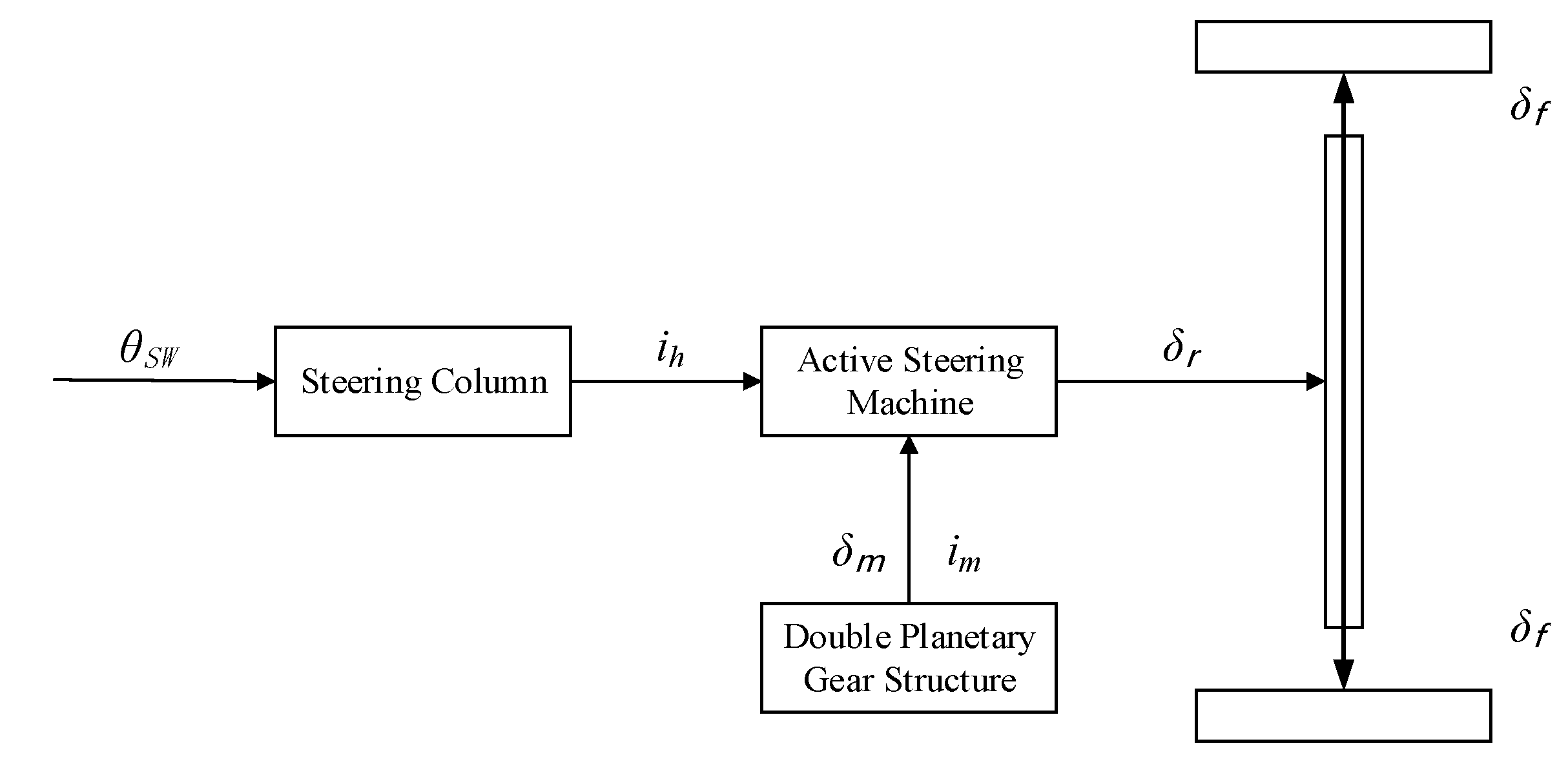
2.1. Active Front-Wheel Steering System

The active front-wheel steering system includes a traditional steering structure, a dual planetary gear train, an active steering motor, a torque sensor and an ECU. The structure of the active front-wheel steering system is shown in Figure 1.
The variable transmission ratio and active steering of the system are realized by the size and direction of the control.
The motion equations are as follows:
δ r ( t ) = 1 i m δ m ( t ) + 1 i h θ S W ( t )
δ r ( t ) = F [ δ f ( t ) ]
δ m ( t ) = i m F [ δ f ( t ) ] i m i h θ S W ( t )
where δr(t)—total angle of rotation; ih—total steering system drive ratio; θSW(t)—steer wheel angle; im—transmission ratio of worm wheel and worm rod; δm(t)—additional angle of motor; and F(x)—the nonlinear function of the total rotation angle δr(t) and front wheel rotation angle δf(t).

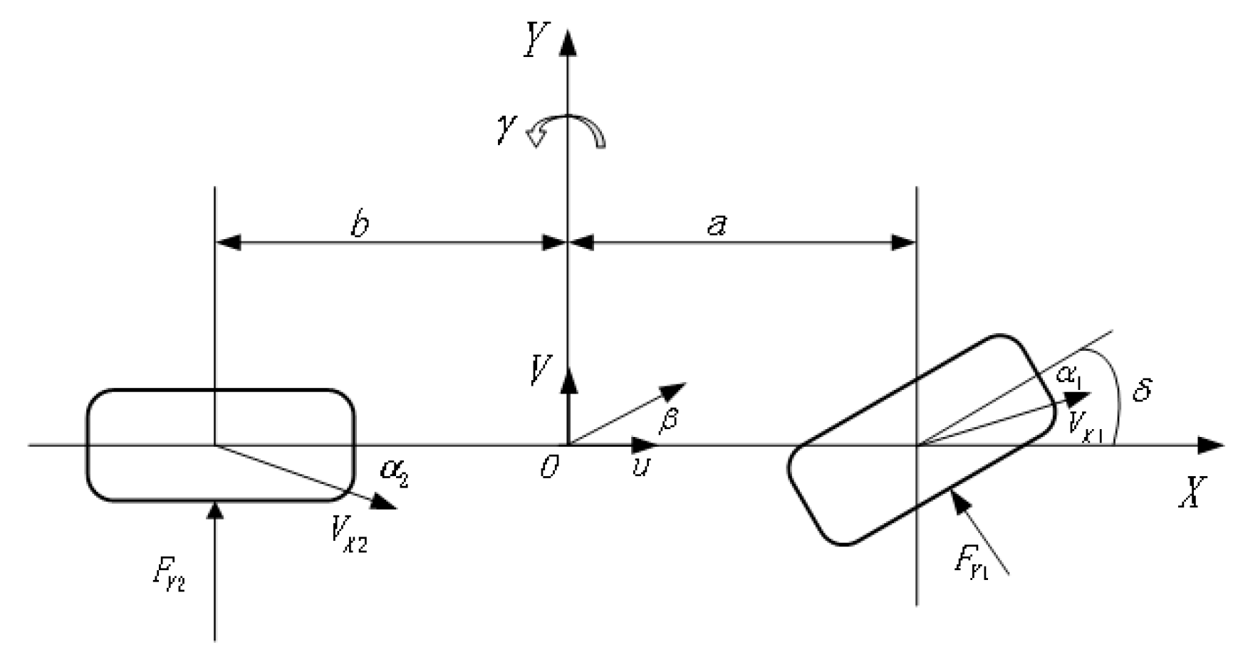
2.2. Vehicle Reference Model and Yaw Velocity Tracker Design

In this paper, the classic three-degrees-of-freedom (DOF-3) nonlinear vehicle model, including yaw, longitudinal and lateral directions, was used to study active front-wheel steering. In order to simplify the follow-up research, it was assumed that the car body is rigid and the road is flat [27]. The DOF-3 model of the vehicle is shown in Figure 2.
Its dynamic equation is constructed as
{ γ ˙ = a 2 k 1 b 2 k 2 I z v x γ + ak 1 bk 2 I z β ak 1 I z δ a y = ak 1 bk 2 mv x γ + k 1 + k 2 m β k 1 m δ
The lateral angle of the center of mass is expressed as follows:
β = arctan ( v x v y )
v ˙ x = v y γ + a x v ˙ y = v x γ + d 1 k 1 d 2 k 2 mv x γ + ( k 1 + k 2 ) v x mv y k 1 m δ
where m is the quality of the vehicle, v is the speed, γ is the yaw rate, β is the center of mass deflection angle, a is the distance from the center of mass to the front axle, b is the distance from the rear axis to the center of mass, δ is the angle of the front wheel rotation, Cr and Cf are the lateral rigidity of the rear axle and the front axle, k1 is the deflection stiffness of the front wheel, k2 is the deflection rigidity of the rear wheel, and Iz is the axis moment of inertia z.
In order to facilitate the design of the controller, the DOF-3 nonlinear model of the vehicle was linearized. Taking the yaw angular velocity as the control objective, the reference model was designed, and the transfer function of the front wheel rotation angle to the yaw angular velocity was
G r ( s ) = r ( s ) δ f ( s ) = b 0 + b 1 s a 0 + a 1 s + a 2 s 2
where b 0 = C f C r ( a + b ) V , b 1 = C f a m V 2 , a 0 = C f C r ( a + b ) 2 + ( C r b + C f a ) mV 2 , a 1 = [ C f ( I z + a 2 m ) + C r ( I z + b 2 m ) ] V , and a 2 = I z mV 2 .
The reference yaw velocity can be obtained from Equation (7):
r * δ f = lim s n G r ( s )

2.3. Tire Model

The tire model is a key part of vehicle dynamics analysis. Most of the force in a car comes from the contact between the tires and the road surface. In this paper, we mainly studied the active front-wheel steering stability of the vehicle on a low-adhesion road. According to vehicle dynamics characteristics, the control efficiency of an active front-wheel steering system on vehicle stability decreases when the tire lateral stiffness changes. However, since the maximum lateral force that can be generated by the tires is the same, an AFS system can still achieve the normal control effect. When AFS works on a low-adhesion road, the stability of the vehicle can be affected by the influence of the adhesion coefficient on the maximum lateral force of the tires. In addition, AFS control over the front wheels cannot be increased unrestricted. Once the tire side slip angle is over-saturated, the stability of the vehicle will be reduced. Especially on a low-adhesion road, the tire side force will soon reach saturation, making the stability of the vehicle more difficult to control. In this paper, the classical “magic formula” was used to establish the nonlinear model of the tires.
y ( x ) = Dsin { Carctan [ Bx E ( Bx arctan ( Bx ) ) ] } { C = a 0 D = a 1 F z 2 + a 2 F z E = a 6 F z 2 + a 7 F z + a 8 BCD = a 3 sin ( arctan ( a 5 F z ) )
where y ( x ) is the tire side force, x is the side slip angle of the tires, B is the stiffness factor, C is the curve shape factor, D is the peak factor, and E is the curvature factor of the curve.
By changing the value of the peak factor D and BCD, the road adhesion coefficient and tire lateral stiffness can be changed.

3. Design of Yaw Moment Controller

In the process of steering, the active front-wheel steering system adjusts the steering system transmission ratio according to the speed and steering wheel angle, and another important role is to control the stability of the vehicle. The overall control strategy logic is shown in Figure 3. It mainly includes a driver, a reference model, a H2/H hybrid robust controller and a vehicle model.

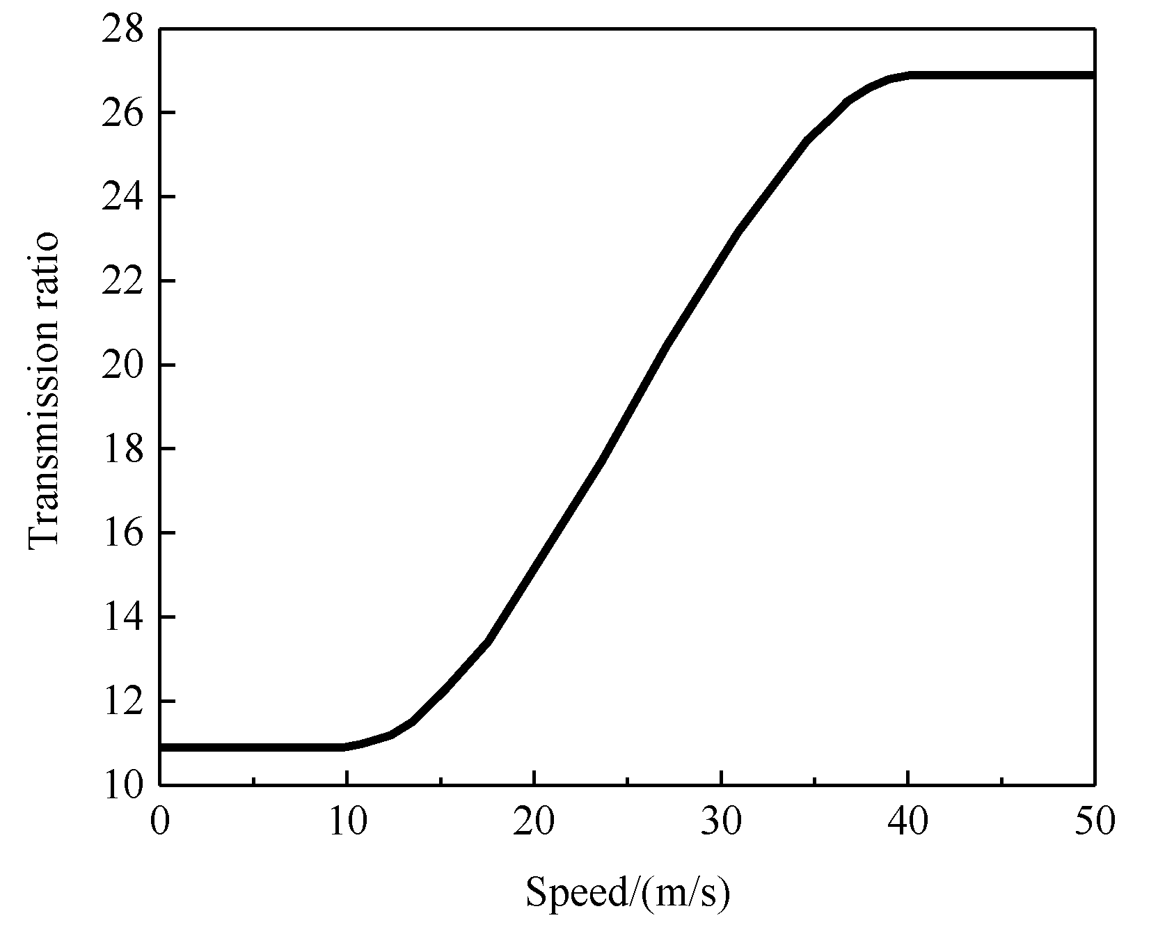
3.1. Variable Angle Transmission Ratio Control Strategy
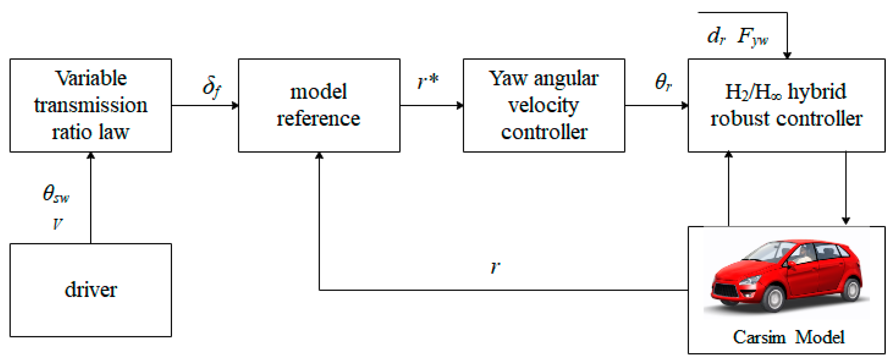
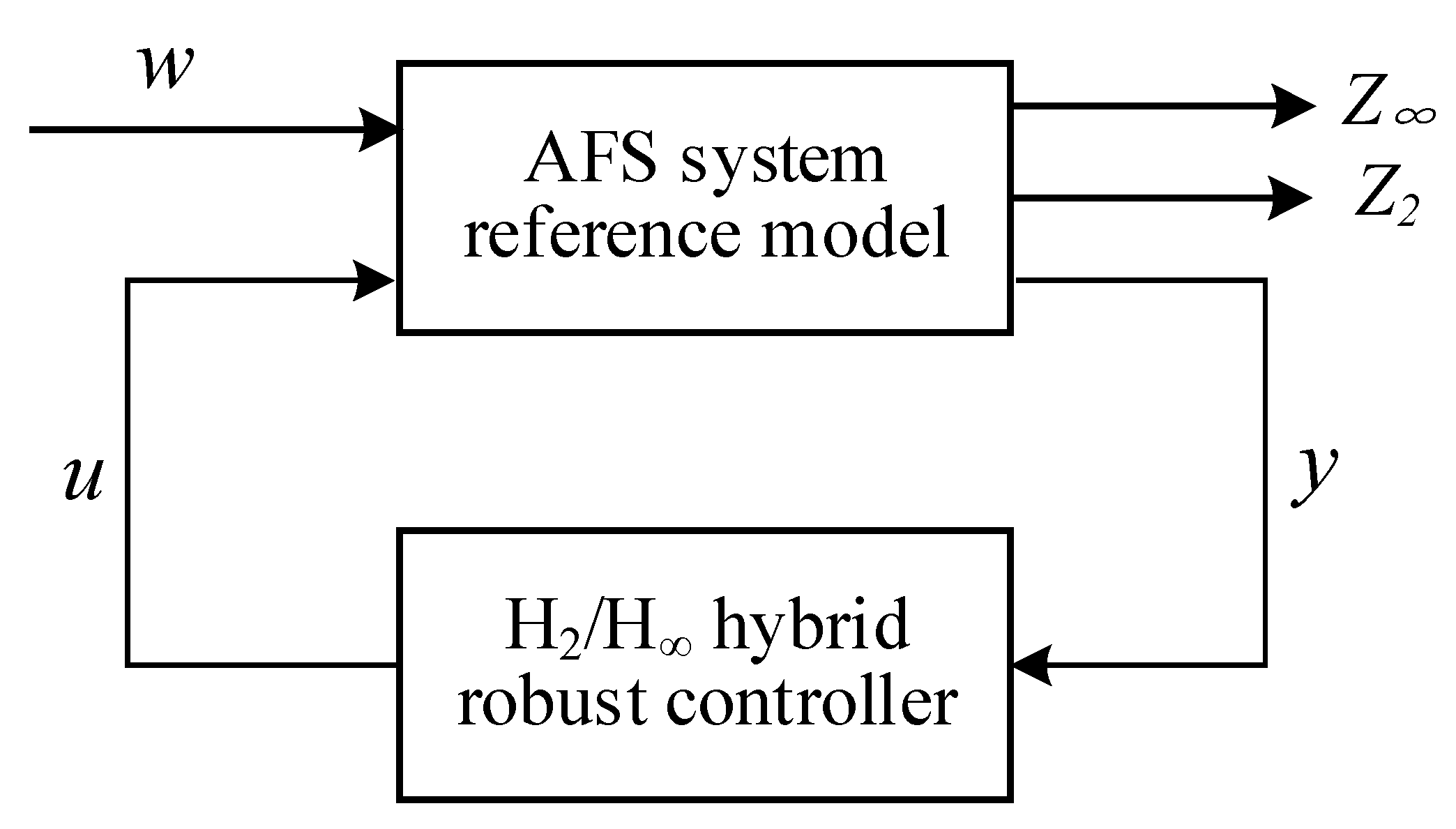
The active front-wheel steering system can control the steering ratio according to the speed to achieve the ideal steering performance, where the key is to establish the law of the variable angle transmission ratio. Results have shown that it is necessary to set a larger gear ratio near the middle of the steering wheel in order to improve the vehicle handling stability. The transmission ratio decreases rapidly with the increase in the steering angle, meaning the steering system has good dynamic characteristics. The ideal transmission ratio of a vehicle steering system is
i = G δ r K s = V K s ( L + K u V 2 )
K u = m ( bC r aC f ) C f C r L
where G δ r is the vehicle yaw angular velocity gain, and K s is the steering sensitivity coefficient of the driver, which was set as 0.275 in this paper.
In order to overcome the defect of designing the variable transmission ratio according to the fixed steering gain, the transmission ratio was fixed below 10 m/s and above 40 m/s. The ideal transmission ratio was adopted in the middle area. Figure 4 shows the variable transmission ratio law of the AFS system, and the law is as follows:
i d = { 10.9                           V < 10 V K s ( L + K u V 2 )     10 V < 40 26.9                           V 40

3.2. H2/H Hybrid Robust Control Strategy Based on Vehicle Stability

In the process of vehicle running, the tire lateral stiffness and road adhesion coefficient μ have a great influence on the vehicle handling performance. As the side force produced by the tires on a low-adhesion road surface will be affected, the working effect of the active front-wheel steering system will be greatly reduced, which seriously affects the stability of the vehicle. Therefore, for this problem, the additional angle input of the AFS system was restricted in this paper to avoid the occurrence of lateral force saturation. In addition, considering the influence of the road adhesion coefficient on vehicle stability control, the control output was limited to further prevent the saturation of the lateral force caused by an excessive tire side slip angle.
The H mixed sensitivity control method can allow the system to have better robustness and interference suppression performance [28]. Therefore, on the basis of H mixed sensitivity control, the H2 norm from the interference input to the control output was optimized to realize the H2/H mixed robust control strategy for active front-wheel steering on a low-adhesion road surface. The schematic diagram of H2/H mixed robust control is shown in Figure 5.
(1)
Sensitivity and complementary sensitivity function
The H2/H hybrid robust control strategy ensures the robust stability of the control system by controlling the actual yaw velocity tracking ideal value. The disturbance inputs of the system are the ideal yaw velocity r*, steering wheel input angle θsw, road disturbance dr, external inputs ω and control input u. Furthermore, y is the measurement output, and Z and Z2 are the outputs to be tuned.
The closed-loop transfer function from W to Z and Z2 is as follows:
S ( s ) = ( I + L ( s ) ) 1
R ( s ) = K ( s ) ( I + L ( s ) ) 1
T ( s ) =   I S ( s )
where L(s) is the open-loop function of the system, S(s) is the sensitivity function, T(s) is the complementary sensitivity function, and R(s) is the control sensitivity function.
(2)
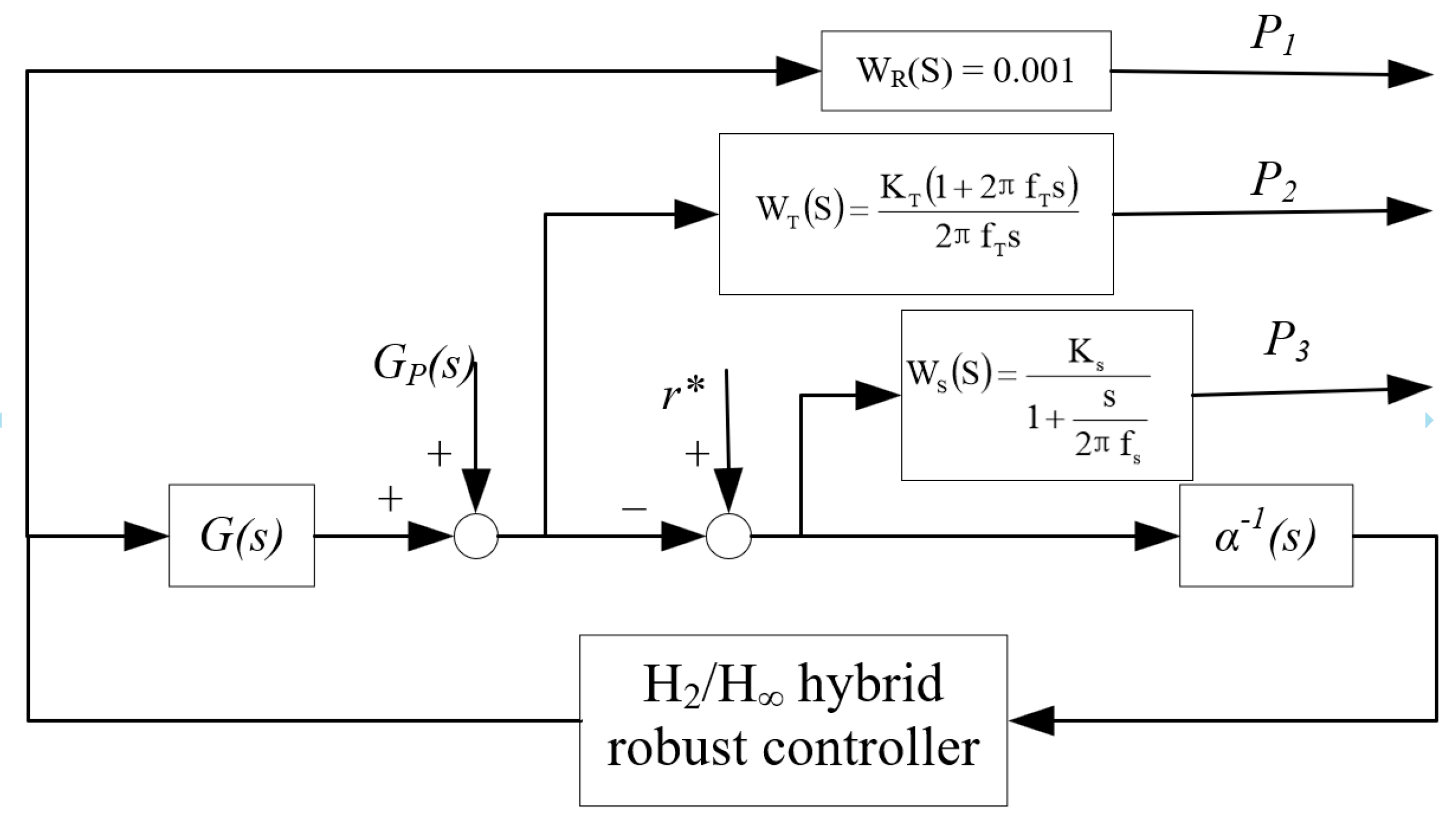
Weighting function selection
Three control outputs, P1, P2 and P3, were introduced, which represent the target tracking ability, anti-jamming ability and robust stability and controller output of the system, respectively. WS(s), WT(s) and WR(s) are the weighting functions of P1, P2 and P3, respectively. The weighted system is shown in Figure 6.
WS(s) selection: WS(s) is the weighting of the sensitivity function S, which is generally a low-pass transfer function to suppress low-frequency interference signals and enhance the ability of target tracking. WS(s) can be selected as follows:
W s = γ W s ˜ ( s )
W s ˜ ( s ) = K s 1 + s 2 π f s
where γ is the gain design parameter, where the larger it is, the better the control performance.
In addition, K s determines the tracking performance of the system, and f s determines the tracking frequency bandwidth of the system. When the value of f s is constant, the larger the value of K s , the smaller the tracking error. Under the condition of a constant f s , the larger the value of K s , the wider the frequency band.
WT(s) selection: WT(s) is the weighting of the complementary sensitivity function T(s), which represents the scalar frequency weighting function of the multiplicative uncertainty and ensures the robustness of the system. WT(s) can be selected as follows:
W T ( s ) = K T ( 1 + 2 π f T s ) 2 π f T s
Due to the nonlinear characteristics of the tires, the transfer function G 0 ( s ) of the design model is uncertain. G (s) is denoted as follows:
G 0 ( s ) = G p ( s ) + G ( s ) = [ 1 + Δ ( s ) ] G ( s )
where G 0 ( s ) is the system uncertain transfer function, G ( s ) is the standard transfer function of the system, and Δ ( s ) is the multiplicative uncertainty of the system. The system is stable when Δ ( s ) = 0 , and the stability condition of the closed-loop system is expressed as
W T ( s ) T ( s ) < 1
WR(s) selection: WR(s) is determined by the control input signal, which is the weighting function that limits the control output energy. The H2 norm was taken as its performance index.
To sum up, the parameters obtained through Simulink simulation were
W s ( s ) = 1800 0.1 s + 100
W T ( s ) = 20 + 20 s 1 + 200 s
W R ( s ) = 0.001
(3)
H2/H robust controller design
In order to reduce the energy of the control output, the H2/H hybrid robust control adopted the H2 norm of the transfer function from w to u as the evaluation index for optimization. The overall control strategy shall meet the following requirements:
Minimize : Subject to :     W R ( s ) K ( s ) S ( s ) 2 W s ( s ) S ( s ) W T ( s ) T ( s ) < 1 Minimize : Subject to :   W R ( s ) K ( s ) S ( s ) 2 W S ( s ) S ( s ) W T ( s ) T ( s ) < 1
where K(s) is the transfer function of the controller.
In order to ensure that the yaw speed control system does not have a steady error, an integrator α1(s) was added in the output circuit of the system. Its expression is as follows:
α ( s ) = s s + 1
According to the generalized control object of S/T, the yaw rate closed-loop system of the AFS system can be written as
{ [ P 1 P 2 P 3 y ] = [ W S W S G 1 W S G 2 W S G 3 0 W S G 0 0 W T G 1 W T G 2 W T G 3 0 W T G 0 0 0 0 0 0 W R α 1 α 1 G 1 α 1 G 2 α 1 G 3 α 1 α 1 G 0 ] [ r * θ sw d r F yw θ sw * ] θ sw * = K ˜ mix y
The final controller is denoted as follows:
K mix ( s ) = K ˜ mix ( s ) α ( s )

4. Experimental Results and Analysis

In this paper, based on CarSim and Simulink, a H2/H hybrid robust control simulation platform for the active front steering of four-wheel independent-drive electric vehicles was developed. CarSim was used to build a four-wheel independent-drive electric vehicle model. The model of AFS and the H2/H hybrid robust control algorithm were built by using Simulink. The main parameters of the vehicle are shown in Table 1.

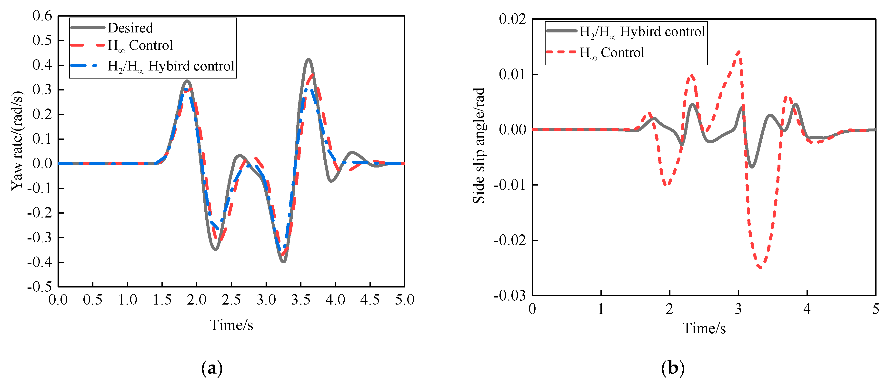
4.1. Simulation of Double-Lane Change Condition

In order to verify the control effect of the H2/H hybrid robust control of the designed AFS system, the ISO3888-2-2002_BS international standard test condition of double-lane change was adopted. The road adhesion coefficient of μ = 0.4 was set, and the simulation was carried out at the speed of 15 m/s. The simulation results are shown in Figure 7.
As it can be seen in Figure 7a, the AFS system can track the path well under both H control and H2/H mixed robust control. By comparison, the yaw velocity of H2/H hybrid robust control is closer to the reference curve than that of H2/H hybrid robust control, which indicates that the AFS system adjusts the weighting function of P1, and the yaw velocity of the vehicle can sufficiently track the ideal yaw velocity. This is because the working range of the tires with H2/H hybrid robust control is mainly concentrated in the linear region and seldom enters the nonlinear region. Figure 7b is the response graph of the side slip angle. According to the graph, the side slip angle of H2/H hybrid robust control is far less than that of H control, which further proves the effectiveness of H2/H hybrid robust control.

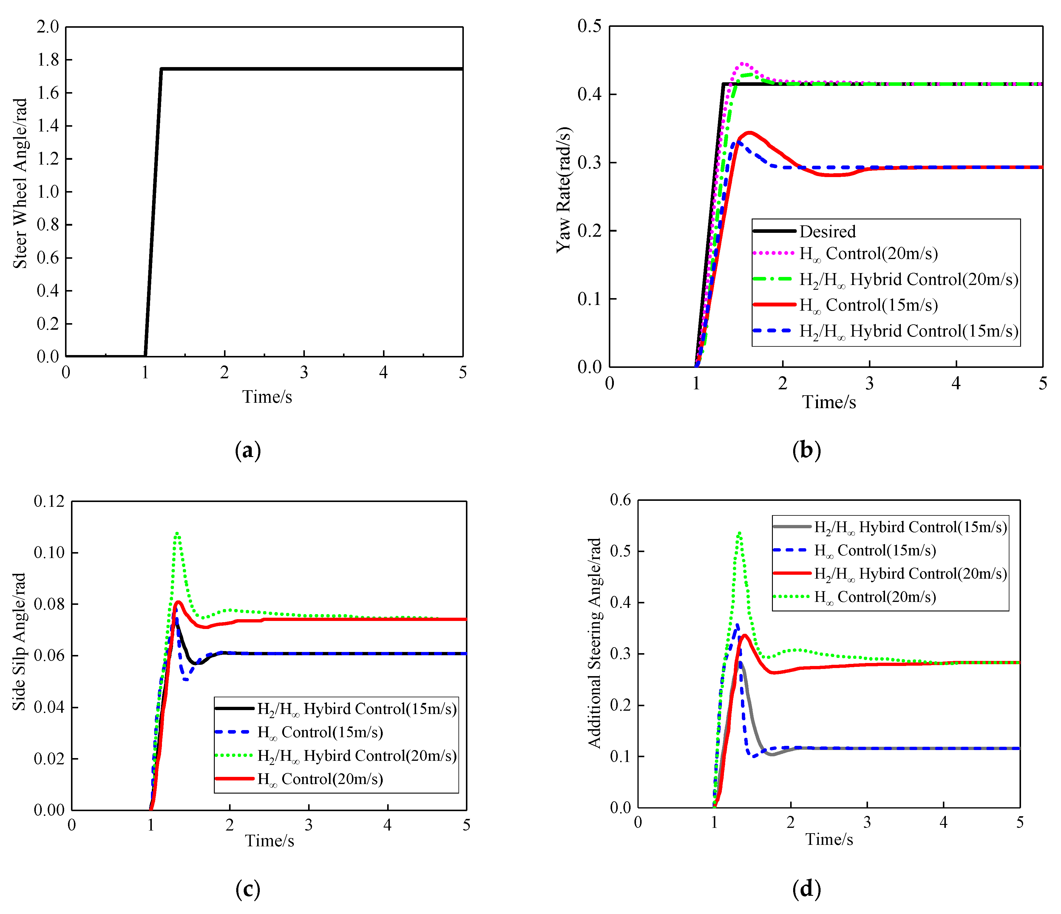
4.2. Step Input Simulation

To verify the control performance of the AFS system under a low adhesion coefficient, we carried out steering wheel step input response analysis under the road adhesion coefficient μ = 0.4. The simulation conditions were as follows: the speed was 15 m/s and 20 m/s; starting from 1 s, the steering wheel rotated at a constant speed to 100° (1.7453293 rad) and was then held. The steering wheel double-lane change input signal is shown in Figure 8a. Simultaneously, the vehicle’s yaw rate, side slip angle and additional steering angle can be observed.
As it can be seen in Figure 8b, under the condition of a low-adhesion road surface, the AFS system with the pendulum angle speed can accurately follow the reference value under H control and H2/H hybrid robust control, regardless of whether it is operated at the speed of 15 or 20 m/s. Among them, H control has a faster response speed and a smaller overshoot than H2/H hybrid robust control. This is because H2/H hybrid robust control adds the H2 norm into the control algorithm, which establishes certain restrictions on the output of the controller, ensures the stability of the vehicle steering process and improves the dynamic response ability of the system. In addition, the AFS system has an obvious steady-state error with a reference value when no control is applied, and the steady-state error is larger without control. As it can be seen in Figure 8c, compared with H control, H2/H hybrid robust control has a relatively smaller side angle of the mass center and a smaller oscillation under the condition of a low-adhesion road surface. This is because the H2 norm is added into the H2/H hybrid robust control, which limits the output of the controller to a certain extent and avoids the violent response of the vehicle mass center side slip angle. Figure 8d shows the additional angle of the steering wheel. The additional angle of the AFS system with H2/H mixed robust control is smaller and tends to a stable state faster. In conclusion, H2/H hybrid robust control is better than H control in ensuring the stability of vehicles.

4.3. HIL Experiment

To verify the real-time performance of the control algorithm, we carried out an HIL experiment. Figure 9 shows the active front-wheel steering hardware-in-the-loop control test bench. It mainly includes a MicroAutobox rapid prototyping development unit, an active front-wheel steering simulator and an acquisition card. The experimental platform adopted CAN communication, and the baud rate was set at 500 Kbit/s.
For further verifying the control ability of the AFS system on a low-adhesion road surface, a sine input test of the steering wheel was carried out under a road adhesion coefficient of μ = 0.4, and the simulated speed was 20 m/s. The experimental data recorded in the recorder were compared with the data obtained in the software offline simulation environment. The simulation results are shown in Figure 10.
Figure 10a is the yaw rate response curve. It can be seen in the figure that H2/H hybrid control and the ideal value are at a minimum on a low-adhesion road surface, and the control performance is better than that of H control, whereas H control is more conservative with obvious hysteria. Figure 10b shows the front wheel side deflection force curve. H2/H hybrid control is obviously better than H control. The same conclusion is obtained, which further verifies the control performance and real-time performance of H2/H hybrid robust control on a low-adhesion road surface.

5. Conclusions

In order to verify the proposed H2/H hybrid robust stability control algorithm for an AFS system on a low-adhesion road surface, a simulation platform was developed. It combines the vehicle model established by CarSim and the AFS system model and control strategy established by Matlab/Simulink. Furthermore, the H2/H of the AFS system was verified in real time, proving the effectiveness of the hybrid robust stability control strategy.
(1)
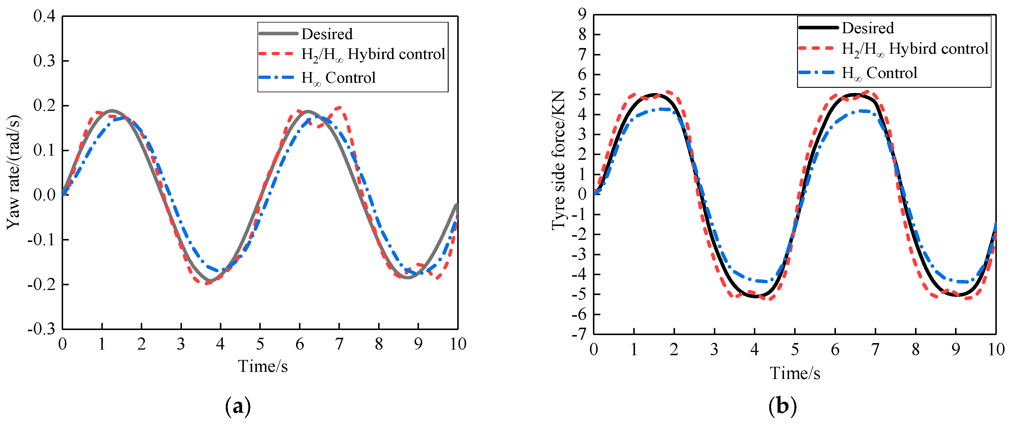
Based on the AFS-HIL simulation platform, the control algorithm was verified. The simulation results show that under a low-adhesion road, mixed H2/H control and the ideal value are at a minimum, the H control performance is better and H has obvious hysteresis control that is more conservative. The algorithm can effectively control the stability of the vehicle on a low-adhesion road and the real-time performance.
(2)
The stability of the active front-wheel steering system was simulated by using double-lane change and step input simulation. Based on vehicle stability, this paper established a mathematical model of the active front-wheel steering control system. In order to improve the vehicle handling stability, a H2/H hybrid robust controller based on the linear matrix inequality method was designed. As a result, the actual vehicle model can sufficiently track the ideal vehicle model. Moreover, CarSim and Simulink were used for joint simulation. The simulation results show the following: The system using H2/H hybrid control has a better performance than that using H control on the studied road. Furthermore, it also has a good robust performance against external interference.
(3)
In this paper, the H2/H hybrid robust control algorithm only considered the displacement control method of active front steering and did not consider the influence of displacement characteristic control on road sensing. In addition, the feedforward compensation and direct control of the steering wheel torque need to be further improved.

Author Contributions

Conceptualization, C.Z. and B.C.; investigation, B.C.; methodology, C.Z. and B.C.; project administration, J.W. and S.L.; resources, J.M. and S.L.; software, R.Z., J.M. and J.W.; supervision, J.M.; validation, C.Z.; writing—original draft, B.C. and R.Z.; writing—review and editing, B.C. and J. W. All authors have read and agreed to the published version of the manuscript.

Funding

This research was funded by the National Natural Science Foundation of China: Research on the Integrated Control Method of the Lateral Stability of Distributed Drive Mining Electric Vehicles (51974229), the Shaanxi Provincial Department of Education Science and Technology plan Project enterprise joint fund (2019JLP-06), the 2021 Youth Innovation Team Construction Scientific Research Program of the Shaanxi Provincial Education Department (21JP071) and the National Key Research and Development Program, China (2018YFB1703402).

Institutional Review Board Statement

Not applicable.

Informed Consent Statement

Not applicable.

Data Availability Statement

Not applicable.

Conflicts of Interest

The authors declare no conflict of interest.

References

  1. Li, X.Y.; Zhang, J. AFS Variable Transmission Ratio Design Considering Road Adhesion Coefficient and Speed. J. Automot. Saf. Energy 2020, 11, 329–336. (In Chinese) [Google Scholar]
  2. Seongjin, Y.; Seungjun, K.; Heesung, Y. Coordinated control with electronic stability control and active front steering using the optimum yaw moment distribution under a lateral force constraint on the active front steering. Proc. Inst. Mech. Eng. Part D J. Automob. Eng. 2016, 230, 581–592. [Google Scholar]
  3. Li, W.Q.; Wu, X.D. Research on Variable Angle Transmission Ratio Characteristics of Steer-by-wire Vehicle. Mech. Electr. Eng. 2019, 36, 422–427. (In Chinese) [Google Scholar]
  4. Li, X.; Shi, X.H.; Li, R.C.; Wang, J.C.; Ma, Y. Sliding Mode Control of Active Front Wheel Steering Based on Ideal Variable Transmission Ratio. Automob. Technol. 2019, 6, 47–52. (In Chinese) [Google Scholar]
  5. Aouadj, N.; Hartani, K.; Fatiha, M. New Integrated Vehicle Dynamics Control System Based on the Coordination of Active Front Steering, Direct Yaw Control, and Electric Differential for Improvements in Vehicle Handling and Stability. SAE Int. J. Veh. Dyn. Stab. NVH 2020, 4, 119–133. [Google Scholar] [CrossRef]
  6. Saïd, M.; Damien, K. Vehicle Handling Improvement by Active Steering. Veh. Syst. Dyn. 2002, 38, 211–242. [Google Scholar]
  7. Bian, J.N.; Wu, L.R.; Liu, X.J.; Xuan, Y.B.; Wang, L.H. Hybrid Sensitivity Robust Control of Unmanned Vehicle. Tactical Missile Technol. 2019, 2, 85–90. (In Chinese) [Google Scholar]
  8. Borrelli, F.; Falcone, P.; Keviczky, T.; Asgari, J.; Hrovat, D. MPC-based approach to active steering for autonomous vehicle systems. Int. J. Veh. Auton. Syst. 2005, 3, 265. [Google Scholar] [CrossRef]
  9. Falcone, P.; Eric Tseng, H.; Borrelli, F.; Asgari, J.; Hrovat, D. MPC-based yaw and lateral stabilization via active front steering and braking. Veh. Syst. Dyn. 2008, 46, 611–628. [Google Scholar] [CrossRef]
  10. Sang, N.; Wei, M.X. Vehicle Active Front Wheel Steering Control Based on ESO and NTSM. J. Nanjing Univ. Aeronaut. Astronaut. 2018, 50, 521–527. (In Chinese) [Google Scholar]
  11. Ahmadian, N.; Khosravi, A.; Sarhadi, P. Integrated model reference adaptive control to coordinate active front steering and direct yaw moment control. ISA Trans. 2020, 106, 85–96. [Google Scholar] [CrossRef]
  12. Zhao, J.; Wong, P.K.; Ma, X.B.; Xie, Z.C. Chassis integrated control for active suspension, active front steering and direct yaw moment systems using hierarchical strategy. Veh. Syst. Dyn. 2017, 55, 72–103. [Google Scholar] [CrossRef]
  13. Zhao, W.; Qin, X. Study on mixed H2/H robust control strategy of four wheel steering system. Sci. Chin. Technol. Sci. 2017, 60, 1–10. [Google Scholar] [CrossRef]
  14. Zhao, W.; Wang, C. Mixed H2/H road feel control of EPS based on genetic algorithm. Sci. Chin. Technol. Sci. 2012, 55, 72–80. [Google Scholar] [CrossRef]
  15. Jin, X.; Yu, Z.; Yin, G.; Wang, J. Improving Vehicle Handling Stability Based on Combined AFS and DYC System via Robust Takagi-Sugeno Fuzzy Control. IEEE Trans. Intell. Transp. Syst. 2017, 19, 2696–2707. [Google Scholar] [CrossRef]
  16. Jing, H.; Wang, R.; Wang, J.; Chen, N. Robust H∞ dynamic output-feedback control for four-wheel independently actuated electric ground vehicles through integrated AFS/DYC. J. Frankl. Inst. 2018, 355, 9321–9350. [Google Scholar] [CrossRef]
  17. Wang, J.X.; Dai, M.M.; Chen, N. Robust output feedback control of active front wheel steering with uncertain parameters. J. Southeast Univ. Nat. Sci. Ed. 2016, 46, 476–482. (In Chinese) [Google Scholar]
  18. Ji, P.K.; Shen, B.; Chen, H.; Zhang, T. Research on Robust Control of Active Steering System. Automot. Eng. 2013, 35, 1092–1098. (In Chinese) [Google Scholar] [CrossRef]
  19. Falcone, P.; Borrelli, F.; Asgari, J.; Tseng, H.E.; Hrovat, D. Predictive active steering control for autonomous vehicle systems. IEEE Trans. Control. Syst. Technol. 2007, 15, 566–580. [Google Scholar] [CrossRef]
  20. Dong, Q.; Ji, X.W.; Liu, Y.L.; Tao, S.X.; Liu, Y.H. Automatic Tracking of Heavy Commercial Vehicle Based on LPV/H Robust Control. J. Tsinghua Univ. Nat. Sci. Ed. 2021, 1–9. (In Chinese) [Google Scholar] [CrossRef]
  21. Li, S.S.; Guo, K.H.; Qiu, T.; Chen, H.; Wang, G.D.; Cui, G. Stability control of active front-wheel Steering Vehicle under extreme conditions. J. Automotive Engineering. 2020, 42, 191–198. (In Chinese) [Google Scholar] [CrossRef]
  22. Wang, R.; Jing, H.; Hu, C.; Yan, F.; Chen, N. Robust H∞ path following control for autonomous ground vehicles with delay and data dropout. IEEE Trans. Intell. Transp. Syst. 2016, 17, 2042–2050. [Google Scholar] [CrossRef]
  23. Wasim, M.; Kashif, A.S.; Ali, A.; Saleem, F. Integrated AFS and DYC using predictive controller for vehicle handling improvement. In Proceedings of the 2021 International Bhurban Conference on Applied Sciences and Technologies (IBCAST), Islamabad, Pakistan, 12–16 January 2021; pp. 568–573. [Google Scholar] [CrossRef]
  24. Zhao, S.E.; Liu, Q.Y. Active Control of Vehicle Steer-by-wire Based on Fractional PID Theory. J. Automot. Saf. Energy 2019, 2, 47–54. (In Chinese) [Google Scholar]
  25. Sun, X.F.; Zhao, J.B. Design of Front Wheel Active Steering System. Tract. Agric. Transp. 2008, 6, 94–95. (In Chinese) [Google Scholar]
  26. Bian, J.N.; Feng, S.S.; Shao, Z.Y.; Li, Y.M.; Nie, W.B. Robust Control of Near Surface Longitudinal Motion of Small Vehicle. J. Beijing Inst. Technol. 2015, 10, 41–45. (In Chinese) [Google Scholar]
  27. Ma, J. Realistic path to promote energy transformation. PetroChina 2020, 2, 14–17. [Google Scholar]
  28. Li, K.Q.; Dai, F.; Li, S.B.; Bian, M.Y. Development Status and Trend of Intelligent Connected Vehicle (ICV) Technology. J. Automot. Saf. Energy 2017, 1, 14. (In Chinese) [Google Scholar]
Figure 1. AFS system.
Wevj 12 00153 g001
Figure 2. DOF-3 vehicle dynamics model.
Wevj 12 00153 g002
Figure 3. Overall control strategy logic diagram.
Wevj 12 00153 g003
Figure 4. AFS variable transmission ratio rule.
Wevj 12 00153 g004
Figure 5. Principle of H2/H hybrid robust control.
Wevj 12 00153 g005
Figure 6. AFS vehicle stability control system structure.
Wevj 12 00153 g006
Figure 7. Double-lane change simulation condition verification: (a) yaw rate; (b) side slip angle.
Wevj 12 00153 g007
Figure 8. Step input simulation verification (when Vx is 20 m/s and 15 m/s, and μ is 0.4). (a) Steering wheel angle; (b) yaw rate; (c) side slip angle; (d) additional steering angle.
Wevj 12 00153 g008
Figure 9. AFS-HIL test platform.
Wevj 12 00153 g009
Figure 10. Sine input HIL simulation verification (when Vx is 20 m/s, and μ is 0.4). (a) Yaw rate; (b) tire side force.
Wevj 12 00153 g010
Table 1. Experimental vehicle parameters.
Parameter NamesNumerical ValueParameter NamesNumerical Value
Width/mm1440Vehicle height/mm1780
Height of center of mass/mm540The moment of inertia around the x-axis/kg·m2288
Total weight/kg1000The moment of inertia around the y-axis/kg·m22031.4
Wheel base/mm2600The moment of inertia around the z-axis/kg·m22031.4
The distance from the center of mass to the front axis/mm1040Reference model front shaft cornering stiffness /N·rad−1−53,388
The distance from the center of mass to the back axis/mm1560Reference model rear shaft cornering stiffness /N·rad−1−35,592
The front wheel radius/mm311Rear wheel radius/mm311
Wheel base/mm1210Tire outside diameter/mm580
Publisher’s Note: MDPI stays neutral with regard to jurisdictional claims in published maps and institutional affiliations.

