
Collaborative Design for Uneven Physical Structures of Multi-Layers in PEMFC


Abstract
:1. Introduction
2. Model Description
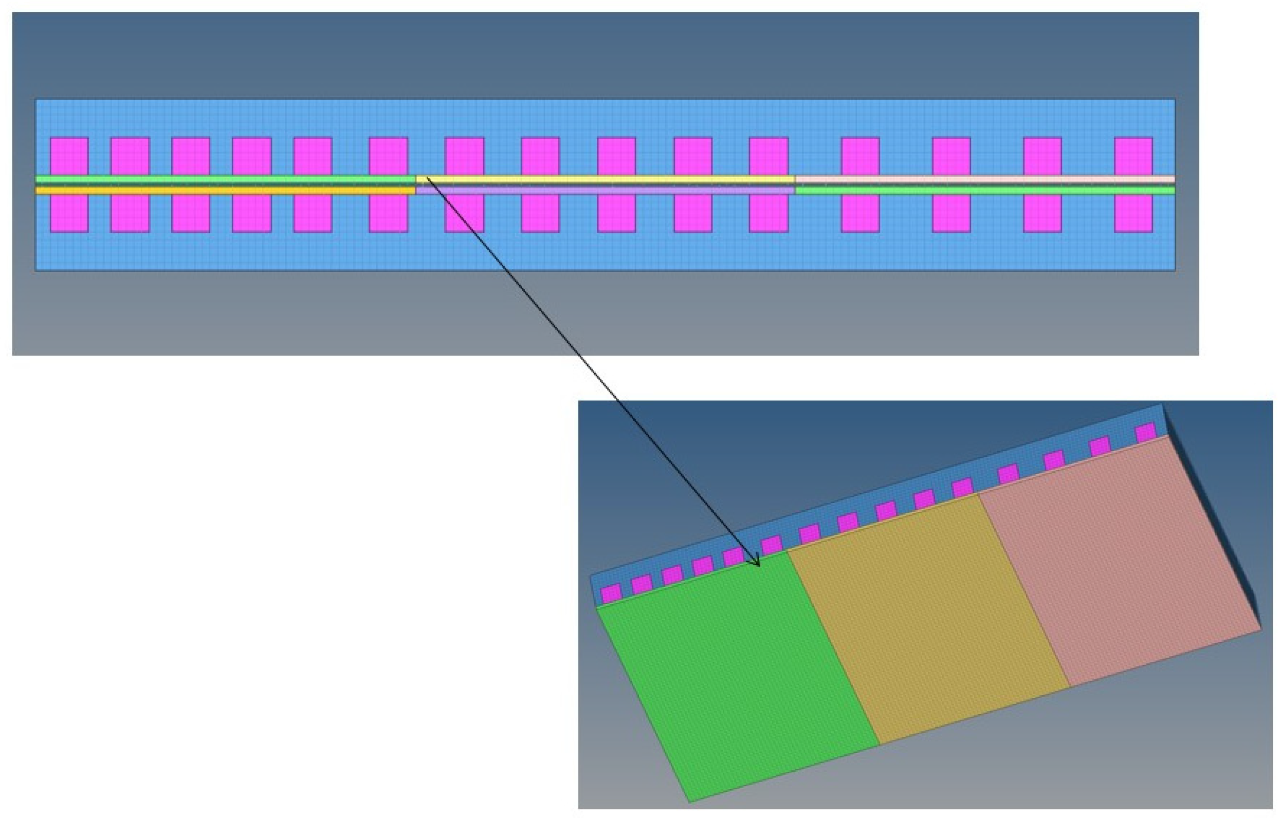
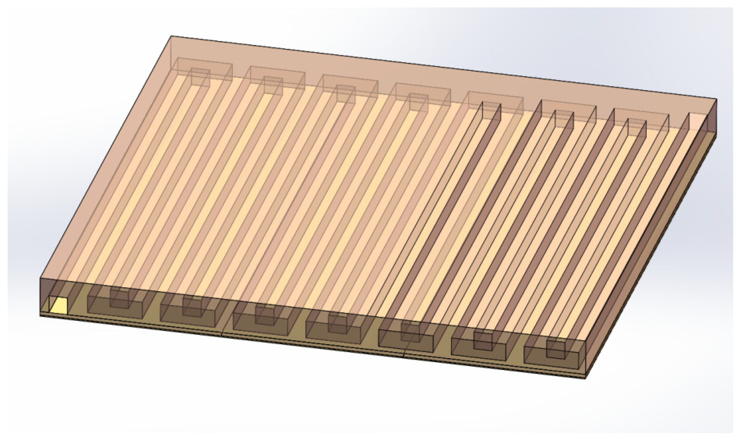
2.1. Numerical Simulation Model
2.2. Governing Equations
- (1)
- The fuel cell operates under steady-state conditions.
- (2)
- The reactant gases introduced are all incompressible ideal gases.
- (3)
- The fuel cell works at a constant temperature.
- (4)
- The gas diffusion layer, catalyst layer and membrane are all isotropic porous media materials.
- (5)
- The fluid flow is laminar.
- (1)
- Mass conservation equation:where ρ is the density; υ is the velocity vector.
- (2)
- Momentum conservation equation:where p is the fluid pressure, μeff is the average viscosity of the mixture, and Sm is the momentum source term. For different regions of the fuel cell, the momentum source term is different.For the gas flow channel:For the gap between the support layer and the catalyst layer:where K is the permeability of the gas diffusion layer or the catalyst layer, and ε is the porosity of the gas diffusion layer.For water transport in the polymer phase, an additional momentum source term is electrokinetic permeability:where εm is the water porosity of the membrane, xm is the volume fraction of ionomer in the catalyst layer, Kf is the electrokinetic permeability, Kp is the hydraulic permeability of the membrane, cf is the fixed charge concentration, nf is the number of sulfonic acid ion charges, F is the Faraday constant and Φm is the ionomer phase potential.
- (3)
- Energy conservation equation:The energy conservation in any area of PEMFC can be described as:where cp is the average specific heat capacity of the mixture, T is the temperature, k is the thermal conductivity, Se is the energy source term, and the subscript eff represents the effectiveness of the porous medium.where ρs, cp,s, and ks respectively represent the temperature, specific heat capacity and thermal conductivity of the solid mixture.The energy source term in the energy conservation equation includes the heat generated by the reaction, resistance heating and (or) the heat generated by evaporation or condensation in the phase change.
- (4)
- Constituent conservation equation:where xi is the mass fraction of the gas component, and Ss,i is the component source or sink. In porous media, Di,eff is a function of the porosity ε and tortuosity τ.where Di is the free flow mass diffusion coefficient.The source term Ss,i in the component conservation equation is all 0, except in the catalyst layer where the components are consumed or produced by the electrochemical reaction. In the catalyst layer, the source terms Ss,i of hydrogen, oxygen, water vapor, and liquid water are:In the water source term, it is assumed that water is produced in liquid form and will evaporate when the adjacent air or oxygen is not saturated.
- (5)
- Charge conservation equation:The current transfer can be described by the governing equation of the conservation of charge; for the current, it is:For the ion current, it is:where is the electrical conductivity in the solid phase, and is the ionic conductivity in the ionomer phase (including the membrane). ϕs is the solid phase potential, ϕm is the electrolytic liquid phase potential, and Sϕ is the source term that refers to the transfer current. In the anode catalyst layer Sϕs = −ja and Sϕm = −ja, in the cathode catalyst layer Sϕs = jc and Sϕm = −jc, and for the rest Sϕ = 0.
3. Results and Discussion
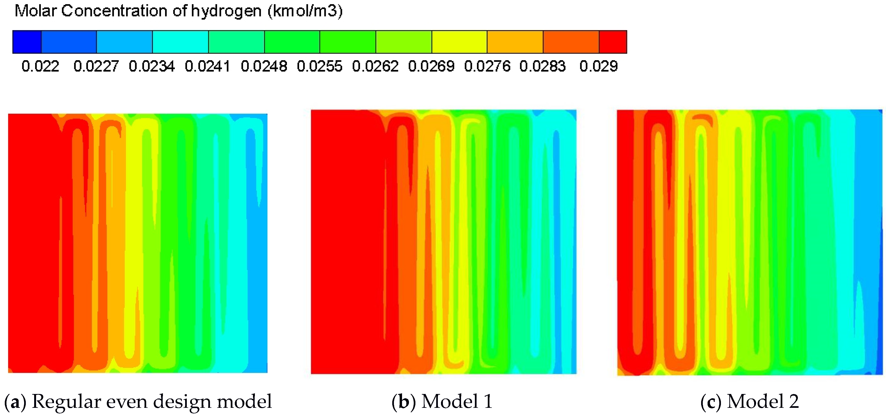
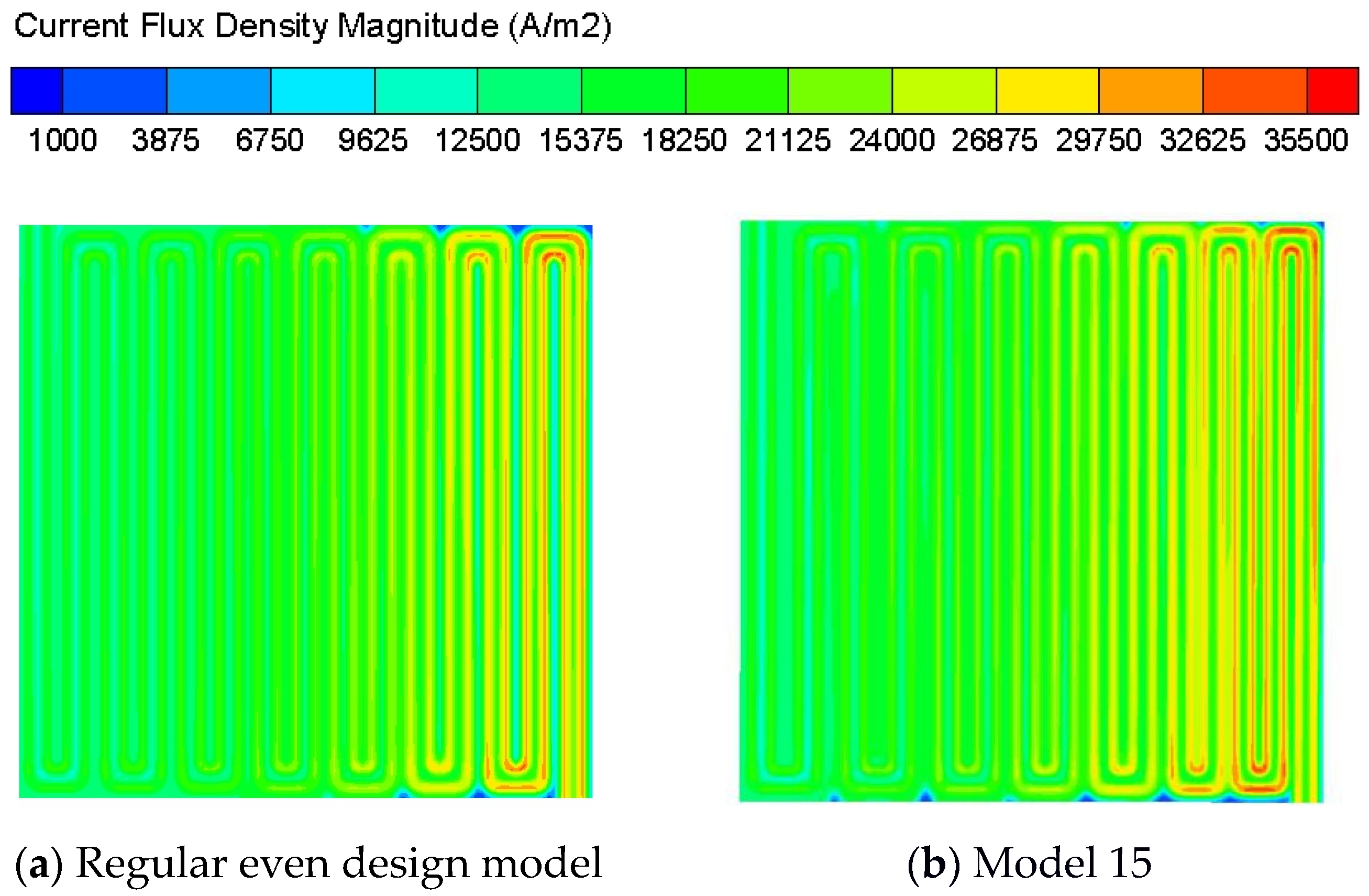
3.1. Effects of Uneven Design of Different Layers
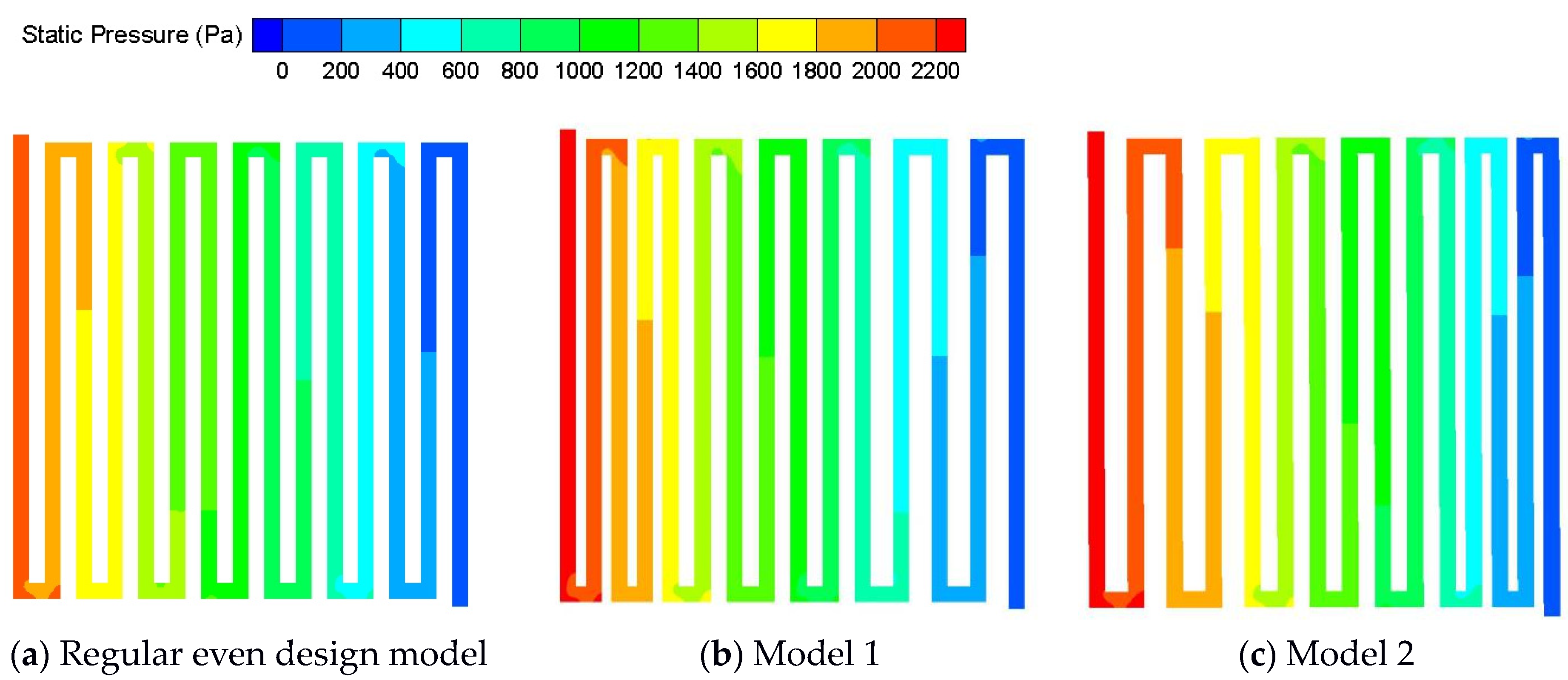
3.2. Collaborative Design of Multilayers in PEMFC
4. Conclusions
Author Contributions
Funding
Conflicts of Interest
References
- Cai, Y.; Fang, Z.; Chen, B.; Yang, T.; Tu, Z. Numerical study on a novel 3D cathode flow field and evaluation criteria for the PEM fuel cell design. Energy 2018, 161, 28–37. [Google Scholar] [CrossRef]
- Kanchan, B.K.; Randive, P.; Pati, S. Numerical investigation of multi-layered porosity in the gas diffusion layer on the performance of a PEM fuel cell. Int. J. Hydrog. Energy 2020, 45, 21836–21847. [Google Scholar] [CrossRef]
- Manso, A.P.; Marzo, F.F.; Mujika, M.G.; Barranco, J.; Lorenzo, A. Numerical analysis of the influence of the channel cross-section aspect ratio on the performance of a PEM fuel cell with serpentine flow field design. Int. J. Hydrog. Energy 2011, 36, 6795–6808. [Google Scholar] [CrossRef]
- Shimpalee, S.; Van Zee, J.W. Numerical studies on rib & channel dimension of flow-field on PEMFC performance. Int. J. Hydrog. Energy 2007, 32, 842–856. [Google Scholar]
- Park, Y.C.; Chippar, P.; Kim, S.K.; Lim, S.; Jung, D.H.; Ju, H.; Peck, D.H. Effects of serpentine flow-field designs with different channel and rib widths on the performance of a direct methanol fuel cell. J. Power Source 2012, 205, 32–47. [Google Scholar] [CrossRef]
- Zhou, P.; Wu, C.W. Numerical study on the compression effect of gas diffusion layer on PEMFC performance. J. Power Source 2007, 170, 93–100. [Google Scholar] [CrossRef]
- Mahmoudi, A.H.; Ramiar, A.; Esmaili, Q. Effect of inhomogeneous compression of gas diffusion layer on the performance of PEMFC with interdigitated flow field. Energy Convers. Manag. 2016, 110, 78–89. [Google Scholar] [CrossRef]
- Chi, P.H.; Chan, S.H.; Weng, F.B.; Su, A.; Sui, P.C.; Djilali, N. On the effects of non-uniform property distribution due to compression in the gas diffusion layer of a PEMFC. Int. J. Hydrog. Energy 2010, 35, 2936–2948. [Google Scholar] [CrossRef]
- Shangguan, X.; Li, Y.; Qin, Y.; Cao, S.; Zhang, J.; Yin, Y. Effect of the porosity distribution on the liquid water transport in the gas diffusion layer of PEMFC. Electrochim. Acta 2021, 371, 137814. [Google Scholar] [CrossRef]
- Rabissi, C.; Zago, M.; Gazdzicki, P.; Guétaz, L.; Escribano, S.; Grahl-Madsen, L.; Casalegno, A. A locally resolved investigation on direct methanol fuel cell uneven components fading: Local cathode catalyst layer tuning for homogeneous operation and reduced degradation rate. J. Power Source 2018, 404, 135–148. [Google Scholar] [CrossRef] [Green Version]
- Jiang, J.; Li, Y.; Liang, J.; Yang, W.; Li, X. Modeling of high-efficient direct methanol fuel cells with order-structured catalyst layer. Appl. Energy 2019, 252, 113431. [Google Scholar] [CrossRef]
- Havaej, P.; Kermani, M.J.; Abdollahzadeh, M.; Heidary, H.; Moradi, A. A numerical modeling study on the influence of catalyst loading distribution on the performance of Polymer Electrolyte Membrane Fuel Cell. Int. J. Hydrog. Energy 2018, 43, 10031–10047. [Google Scholar] [CrossRef]
- Ebrahimi, S.; Roshandel, R.; Vijayaraghavan, K. Power density optimization of PEMFC cathode with non-uniform catalyst layer by Simplex method and numerical simulation. Int. J. Hydrog. Energy 2016, 41, 22260–22273. [Google Scholar] [CrossRef]
- Ebrahimi, S.; Ghorbani, B.; Vijayaraghavan, K. Optimization of catalyst distribution along PEMFC channel through a numerical two-phase model and genetic algorithm. Renew. Energy 2017, 113, 846–854. [Google Scholar] [CrossRef]
- Zheng, Z.; Yang, F.; Lin, C.; Zhu, F.; Shen, S.; Wei, G.; Zhang, J. Design of gradient cathode catalyst layer (CCL) structure for mitigating Pt degradation in proton exchange membrane fuel cells (PEMFCs) using mathematical method. J. Power Source 2020, 451, 227729. [Google Scholar] [CrossRef]
- Yin, K.M.; Cheng, B.S.; Chiang, K.W. Non-uniform agglomerate cathode catalyst layer model on the performance of PEMFC with consideration of water effect. Renew. Energy 2016, 95, 191–201. [Google Scholar] [CrossRef]
- Soler, J.; Hontanon, E.; Daza, L. Electrode permeability and flow-field configuration: Influence on the performance of a PEMFC. J. Power Source 2003, 118, 172–178. [Google Scholar] [CrossRef]


| Parameters | Value |
|---|---|
| Channel width | 1 mm |
| Channel height | 1 mm |
| Rib width | 1 mm |
| GDL thickness | 0.2 mm |
| Catalyst layer thickness | 0.026 mm |
| Membrane thickness | 0.05 mm |
| Parameters | Value | Parameters | Value |
|---|---|---|---|
| Operating temperature | 353 K | Operating pressure | 1 atm |
| Anode stoichiometric flow rate | 1.5 | Cathode stoichiometric flow rate | 2 |
| Anode relative humidity | 30% | Cathode relative humidity | 30% |
| GDL porosity | 0.5 | CL porosity | 0.5 |
| Anode concentration exponent | 0.5 | Cathode concentration exponent | 1 |
| Anode exchange coefficient | 2 | Cathode exchange coefficient | 2 |
| Rib Width | Anode Gas Diffusion Layer | Cathode Gas Diffusion Layer | Anode Catalyst Layer | Cathode Catalyst Layer |
|---|---|---|---|---|
| - | - | - | - | - |
| uneven (↑↓) | uneven (↑↓) | - | - | - |
| uneven (↑↓) | - | uneven (↑↓) | - | - |
| uneven (↑↓) | uneven (↑↓) | uneven (↑↓) | - | - |
| uneven (↑↓) | - | - | uneven (↑↓) | - |
| uneven (↑↓) | - | - | - | uneven (↑↓) |
| uneven (↑↓) | - | - | uneven (↑↓) | uneven (↑↓) |
| uneven (↑↓) | uneven (↑↓) | - | uneven (↑↓) | - |
| uneven (↑↓) | - | uneven (↑↓) | - | uneven (↑↓) |
| uneven (↑↓) | uneven (↑↓) | uneven (↑↓) | uneven (↑↓) | uneven (↑↓) |
| Model | Rib Width /(mm) | Porosity (Anode GDL) | Porosity (Cathode GDL) | Porosity (Anode CL) | Porosity (Cathode CL) | Growth Rate |
|---|---|---|---|---|---|---|
| 1 | 0.6 1 1.4 | 0.5 | 0.5 | 0.5 | 0.5 | −6.59% |
| 2 | 1.4 1 0.6 | 0.5 | 0.5 | 0.5 | 0.5 | 8.10% |
| 3 | 1 | 0.3 0.5 0.7 | 0.5 | 0.5 | 0.5 | −0.21% |
| 4 | 1 | 0.5 | 0.3 0.5 0.7 | 0.5 | 0.5 | 2.40% |
| 5 | 1 | 0.5 | 0.5 | 0.3 0.5 0.7 | 0.5 | −0.03% |
| 6 | 1 | 0.5 | 0.5 | 0.5 | 0.3 0.5 0.7 | 0.19% |
| 7 | 1 | 0.7 0.5 0.3 | 0.5 | 0.5 | 0.5 | 0.09% |
| 8 | 1 | 0.5 | 0.7 0.5 0.3 | 0.5 | 0.5 | −2.80% |
| 9 | 1 | 0.5 | 0.5 | 0.7 0.5 0.3 | 0.5 | 0.01% |
| 10 | 1 | 0.5 | 0.5 | 0.5 | 0.7 0.5 0.3 | −0.22% |
| 11 | 1 | 0.3 0.5 0.7 | 0.3 0.5 0.7 | 0.5 | 0.5 | 2.09% |
| 12 | 1 | 0.5 | 0.5 | 0.3 0.5 0.7 | 0.3 0.5 0.7 | 0.16% |
| 13 | 1 | 0.5 | 0.3 0.5 0.7 | 0.5 | 0.3 0.5 0.7 | 2.61% |
| 14 | 1 | 0.3 0.5 0.7 | 0.3 0.5 0.7 | 0.3 0.5 0.7 | 0.3 0.5 0.7 | 2.24% |
| 15 | 1.4 1 0.6 | 0.5 | 0.3 0.5 0.7 | 0.5 | 0.3 0.5 0.7 | 10.60% |
| Regular Even Design Model | Model 1 | Model 2 | |
|---|---|---|---|
| Standard deviation | 0.00223376 | 0.00232341 | 0.00204100 |
Publisher’s Note: MDPI stays neutral with regard to jurisdictional claims in published maps and institutional affiliations. |
© 2021 by the authors. Licensee MDPI, Basel, Switzerland. This article is an open access article distributed under the terms and conditions of the Creative Commons Attribution (CC BY) license (https://creativecommons.org/licenses/by/4.0/).
Share and Cite
Yang, Q.; Chen, S.; Xiao, G.; Li, L. Collaborative Design for Uneven Physical Structures of Multi-Layers in PEMFC. World Electr. Veh. J. 2021, 12, 148. https://doi.org/10.3390/wevj12030148
Yang Q, Chen S, Xiao G, Li L. Collaborative Design for Uneven Physical Structures of Multi-Layers in PEMFC. World Electric Vehicle Journal. 2021; 12(3):148. https://doi.org/10.3390/wevj12030148
Chicago/Turabian StyleYang, Qinwen, Shujun Chen, Gang Xiao, and Lexi Li. 2021. "Collaborative Design for Uneven Physical Structures of Multi-Layers in PEMFC" World Electric Vehicle Journal 12, no. 3: 148. https://doi.org/10.3390/wevj12030148
APA StyleYang, Q., Chen, S., Xiao, G., & Li, L. (2021). Collaborative Design for Uneven Physical Structures of Multi-Layers in PEMFC. World Electric Vehicle Journal, 12(3), 148. https://doi.org/10.3390/wevj12030148