Article

Research on Anti-Skid Control Strategy for Four-Wheel Independent Drive Electric Vehicle

School of Mechanical Engineering, Xi’an University of Science and Technology, Xi’an 710054, China
*
Author to whom correspondence should be addressed.
World Electr. Veh. J. 2021, 12(3), 150; https://doi.org/10.3390/wevj12030150
Submission received: 3 August 2021 / Revised: 26 August 2021 / Accepted: 3 September 2021 / Published: 8 September 2021

Abstract

:
Four-wheel independent drive electric vehicles have become the latest development trend of electric vehicles due to their simple structure and high control accuracy. Aiming at the sliding problem of four-wheel independent driving electric vehicles in the driving process, a driving anti-skid control strategy is designed. The strategy includes two contents: (1) a road recognition module that tracks the best slip rate in real time; (2) a slip rate control module that uses fuzzy PID control. Then, based on Carsim and MATLAB/Simulink, the vehicle dynamics model, tire model and driving anti-skid control model are established. A simulation of the driving anti-skid control algorithm is carried out to verify the feasibility of the control strategy. Finally, based on the built-up dSPACE semi-physical experimental simulation platform, the verification was carried out, and the test and simulation results were compared to verify the effective feasibility of the driving anti-skid control strategy.

1. Introduction

With the rise in energy costs and the tightening of regulations on ground vehicle exhaust emissions, electric vehicles have become an inevitable trend in the development of the automotive industry [1,2]. Four-wheel independent drive electric vehicles have become a new hot spot actively researched and developed by the automobile industry in various countries [3]. Compared with traditional electric vehicles, four-wheel independent drive electric vehicles have simple mechanical structure, high transmission efficiency, and high precision of torque control of each driving wheel [4,5]. Researchers have launched a study on its control system [6]. The anti-skid system ASR of the vehicle is to prevent the vehicle’s stability from degrading due to the slipping of the drive wheels during the driving process [7]. It is a device that improves the safety and stability of the vehicle. Much research on the anti-skid system of distributed driving electric vehicles have been carried out at home and abroad [8,9].
Japanese researchers developed the “UOT Electric March” wheeled electric car [10]. Taking the single-wheel vehicle model as the research object, an optimal control algorithm based on model tracking was proposed. The TogLitti Institute of Technology in Russia studied the two-wheeled independent driving electric vehicle and adopted the sliding mode variable structure control algorithm to study the ASR control system [11]. American researchers have conducted research on driving anti-skid control strategies. They were based on optimal control, a new kind of basic research ASR Control method, and used a four-wheel independent drive electric vehicle as the experimental object to control [12]. In summary, the U.S, Japan and other countries have actively started the research of driving anti-skid control systems, and have also achieved certain results. However, due to the complexity of the vehicle itself, and other factors, there are also road conditions, driver factors, wind resistance, and so on. The research on driving anti-skid control systems has not reached the ideal state, and further in-depth study is needed. The scholars of Tsinghua University took the all-wheel drive electric vehicle as the prototype and adjusted the sliding surface parameters in real time. A driving anti-skid control system that takes the slip rate as the control target was calculated. The control system improved the torque output of the motor, and to a certain extent, it reduced the overshoot and oscillation caused by other control algorithms. Zhang lipeng proposed a control method combining the optimal slip rate PI control and dynamic equal torque drive control [13]. Yu zhuoping designed a robust sliding mode variable structure controller to control the slip rate for the characteristics of distributed drive electric buses [14].
So far, the driving anti-skid technology is not mature enough at home or abroad. Although current driving anti-skid technology can solve the problem of excessive wheel slip during acceleration or starting and improve the vehicle’s adhesion, it can still be dangerous to skid on roads with low road adhesion or at high speeds when making sharp turns. Most of the existing automobile anti-skid control strategies adopt logic threshold control. Since the vehicle motion process is a non-linear, real-time deformable drive system, the logic gate limit control cannot represent the road surface information in the vehicle motion process in real time. Further, the best slip rate and road adhesion coefficient of the vehicle on the current road surface cannot achieve a good control effect. Therefore, this paper proposes a driving anti-skid control strategy based on road recognition. Based on the establishment of the dynamic model, a road recognition module and a slip rate control module are designed.
The main research contents of this paper are as follows. In Section 2, according to the control objectives, a basic mathematical model of four-wheel independent drive electric vehicle is established. Section 3 designs the overall scheme of driving anti-skid control strategy, including the design of pavement identification module and slip rate control module. In Section 4, simulation analysis and semi-physical simulation are carried out on the proposed drive anti-skid control strategy. Finally, Section 5 summarizes the main conclusions, innovations and limitations, as well as further proposed studies.

2. Dynamic Model Establishment

2.1. Vehicle Dynamics Model

This paper uses the seven degrees of freedom vehicle dynamic model for the vehicle’s coordinate system, including the vehicle’s longitudinal motion, the lateral motion, the yaw motion, and the four-wheel rotation [15]. As shown in Figure 1, the roll and the vertical motion of the vehicle are ignored in the model. Establish vehicle motion coordinates, and the forward direction of the vehicle is the forward direction of the vehicle when it is traveling. The origin of the coordinates is the position of the center of mass when the vehicle is stationary. The direction parallel to the ground and the forward direction of the vehicle is the positive direction of the X axis, the direction pointing to the left side of the driver is the positive direction of the Y axis, and the direction pointing upward through the center of mass is the positive direction of the Z axis.
In the above formula, m is the quality of the whole vehicle; ms is the spring mass; ax is the longitudinal acceleration of the car; ay is the lateral acceleration of the car; A is the windward area; CD is the wind resistance coefficient; δ is the steering angle of the front wheels of the vehicle; Fxi is the longitudinal force of each wheel; Fyi is the lateral force of each wheel; Fw is wind resistance; ρ is the air density; V is the speed; μ is the longitudinal speed; v is the lateral speed; γ is the yaw rate; Iz is the moment of inertia of the vehicle around the axis; df is the front axle track; dr is the track of the rear axle; and a, b are the distances from the center of mass of the vehicle to the front and rear axles, respectively.
Longitudinal kinematics equation:
m a x = ( F x 1 + F x 2 ) cos δ ( F y 1 + F y 2 ) sin δ + F x 3 + F x 4 F w
Lateral kinematics equation:
m a y = ( F x 1 + F x 2 ) sin δ + ( F y 1 + F y 2 ) cos δ + F y 3 + F y 4
The equation of yaw motion:
I z γ = [ ( F y 1 + F y 2 ) cos δ + ( F x 1 + F x 2 ) sin δ ] a ( F y 3 + F y 4 ) b + ( F x 2 F x 1 ) cos δ d f 2 + ( F y 1 F y 2 ) sin δ d f 2 + ( F x 4 F x 3 ) d r 2
The equation of motion of the wheel is:
I w ω i = T d i F x i R

2.2. Tire Model

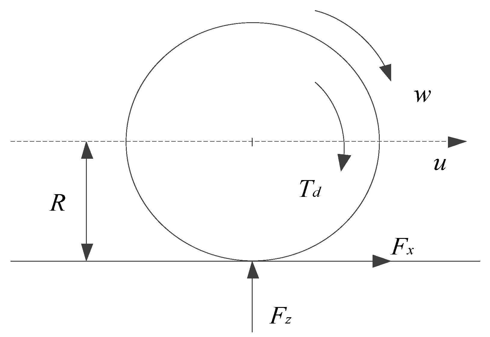
The force and moment of the car movement have a great influence on the stability and smoothness of the car, so the choice of tires is particularly important in order to obtain wheel slip angle, vertical load, etc. The movement process of vehicle tires has a vital influence on vehicle stability control and driving anti-skid control. In this article, assuming that the wheels do not move in the vertical direction when the vehicle is moving, the force on the wheels is as shown in the Figure 2.
Among them, w is the moment of inertia of the tire, Td is the driving torque of the driving wheel, Fx is the longitudinal force of the tire, R is the rolling radius of the tire, and Td = 0 for the non-driving wheel.
Because the longitudinal force, lateral force, and tire side angle of the tire are the main factors that affect the stability of the vehicle, a more accurate Dugoff model is applied. The modeling process is as follows:
Tire longitudinal force:
F x i = C x s 1 + s f ( λ i )
Tire lateral force:
F y i = C y t a n α i 1 + s f ( λ i )    
where λ i is obtained by the following formula:
λ i = φ x i F z i ( 1 + s ) 2 ( C x s ) 2 + ( C y t a n α i ) 2
λ i meet the following conditions:
f ( λ i ) = { ( 2 λ i ) λ i ( λ i 1 ) 1 ( λ i > 1 )
where, C x is the longitudinal stiffness of tires; C y is the lateral stiffness of tires; α i is the tire side angle.

3. Design on Driving Anti-Skid Control Strategy

Driving anti-skid control is an important aspect of improving vehicle stability. Due to the limitation of the driving anti-skid technology, most of the existing anti-skid control strategies for automobile drive only use logic gate limit control with simple structure and convenient control system [16]. Since the vehicle motion process is a non-linear and real-time transformable drive system, the control system cannot represent the road surface information during the vehicle movement and the optimal slip rate on the current road surface of the vehicle in real time [17]. Additionally, the road surface adhesion coefficient cannot achieve a good control effect. Therefore, this paper designs a controller that includes a road surface recognition module and a slip rate module, and uses the front left wheel as an example to design a driving anti-skid control strategy.
As shown in Figure 3, the working process of the driving anti-skid control system is:
(1)
The current slip rate of the driving wheels and the road adhesion coefficient is calculated according to the vehicle dynamics model, tire model and motor model. The road slip rate and the wheel adhesion coefficient are used as the input of the road surface recognition controller, the current road surface condition is determined according to the road surface recognition controller, and the road surface parameters of the current road surface are calculated.
(2)
Then, the slip rate control module is input, and the optimal slip ratio suitable for the current road surface is determined through the control algorithm. By adjusting the pedal signal, the wheel speed and the vehicle speed can be adjusted in realtime to prevent the wheel from slipping.

3.1. Wheel Slip Mechanism

On low-adhesion roads, the driving force that the road can provide is limited. When the driving force provided by the drive system of the vehicle is much greater than the current road can provide, the wheels will experience serious slippage or sideways movement. The overturning phenomenon reduces the safety and stability of the vehicle.
Taking the left front wheel of the driving wheel as an example, the product of the vertical reaction force of the wheel on the ground and the road adhesion coefficient is defined as the adhesion. When the wheels are not skidding, the driving force provided by the vehicle’s power system should be less than the adhesion provided by the road surface. Therefore, in order to prevent the vehicle from slipping during driving, the following conditions are satisfied:
F d F z φ   ( μ = F d F z φ )
where, F d represents the driving force provided by the power system to the driving wheel; φ indicates the pavement adhesion coefficient; F Z represents the opposing force of the drive wheel, and μ means the adhesion coefficient, known as adhesion.
When the vehicle is driving on a low-adhesion road surface, the driving wheels are usually in a combined rolling and sliding state. In order to describe the co-existence of rolling and sliding, the slip rate λ is introduced:
λ = ω r v ω r × 100 %
Among them, ω is the angular velocity of the wheel; γ is the wheel rolling radius; v is the longitudinal velocity of the vehicle.
From the above formula, in the driving process of the car, ω r v , so 0 λ 1 ; when the wheel slip rate is 0, that is ω r = v , the vehicle and the wheel have no relative moving speed, that is, there is no wheel slip phenomenon; when the slip rate is 100%, that is, when v = 0, the relative speed between the vehicle and the wheel is ω r , indicating that the wheel has completely slipped; at that time 0 < λ < 1 , the wheel has both rolling motion and sliding motion. Therefore, the slip rate indicates the degree of wheel slippage. Larger means more severe wheel slip; smaller means less wheel slip.
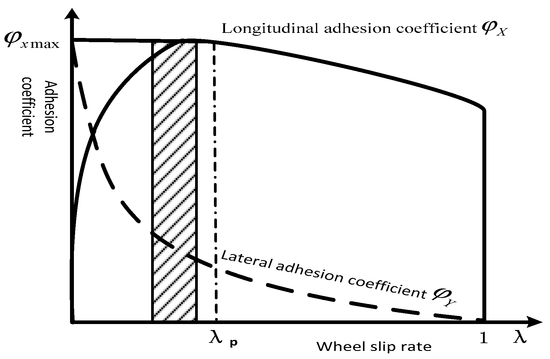
The purpose of driving anti-skid is to increase the driving force of the road surface and reduce the slippage of the wheels during driving. According to a large amount of experimental data, the relationship between the adhesion coefficient φ and the slip rate λ is shown in Figure 4.
Considering the lateral stability and longitudinal stability of the vehicle, the wheel slip ratio control between the peak adhesion coefficient φ x m a x and the corresponding slip rate λ p is the best ideal interval, the value range of λ is (0.05, 0.2). The driving anti-skid control system of the vehicle is to monitor the actual slip rate of the tires in real time during the driving process of the vehicle and constantly adjust the actual slip rate to keep the slip rate of the wheel in an ideal range, reducing the degree of wheel slip and improving the stability of the vehicle.

3.2. Road Identification Module

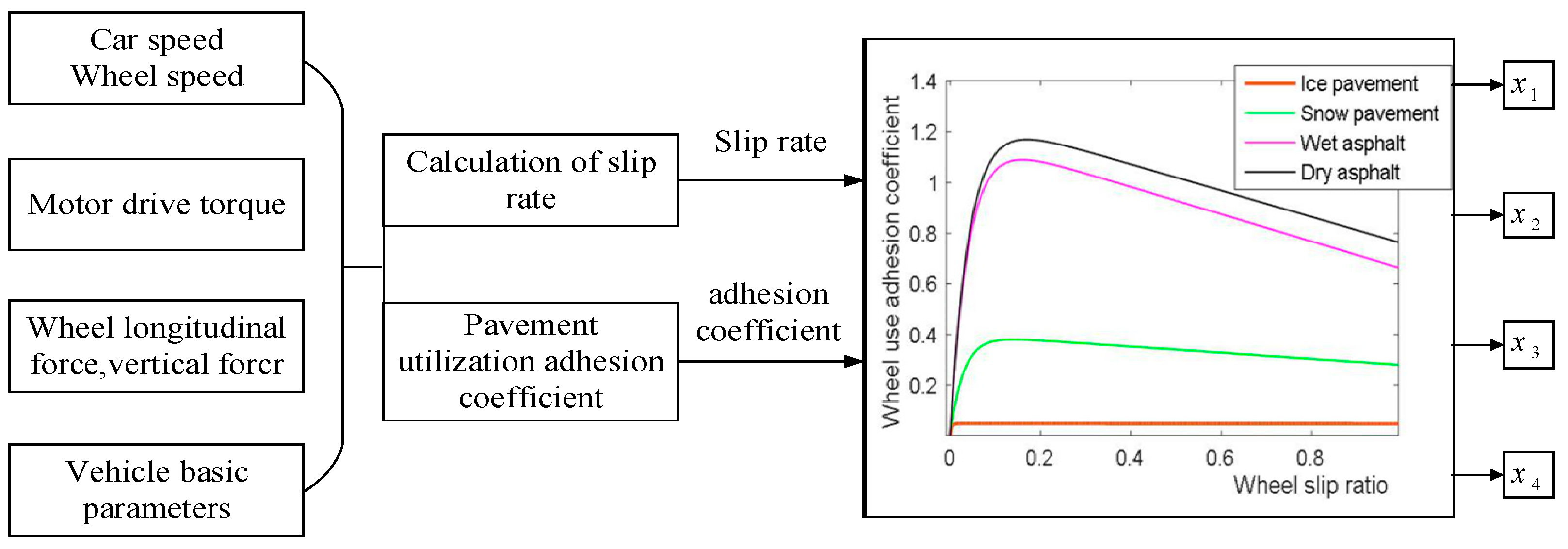
The driving slip of the vehicle must first recognize the current road surface. As shown in Figure 5, using the wheel slip ratio and the road surface adhesion coefficient as the input of the road surface recognition module, the weight coefficient of the current road surface is calculated by the fuzzy control and other corresponding algorithm modules, which is compared with the standard road surface adhesion coefficient-slip rate curve. By comparison, the optimal slip rate and peak adhesion coefficient of the current road surface are obtained.
Since different roads have different characteristics, four typical roads are selected as the basis of road recognition control strategies. The basic pavements are dry asphalt pavement, wet asphalt pavement, snow pavement, and ice pavement.
Standard road surface curve u-s was obtained:
μ ( s ) = C 1 ( 1 e c 2 s ) C 3 s
Optimum slip rate:
S o p t i = 1 C 2 I n C 1 C 2 C 3
Maximum adhesion coefficient of road surface:
μ m a x = C 1 C 3 C 2 ( 1 + I n C 1 C 2 C 3 )
In Table 1, C1, C2, and C3 are the curve fitting coefficient, and their value is related to the road condition. The optimal (11)–(13) slip rate and the maximum adhesion coefficient of the road surface are calculated according to the formula. In the case of the same slip rate, the adhesion coefficients of different pavements are very different. For example, the adhesion coefficient of high-adhesion pavement is larger than that of low-adhesion pavement, that is, the adhesion coefficient of dry asphalt pavement is much larger than that of ice pavement. The relationship of the road parameters of the four typical roads is known, which provides a basis for the road recognition module to infer the type of the current road.
The road recognition fuzzy controller chooses two input multiple output control structures. The controller design is shown in Figure 6. The fuzzy control module is a fuzzy process that associates the input slip rate with the clarity of the road surface adhesion coefficient. Meanwhile, reasonable fuzzy control rules are formulated to process the fuzzy information. The fuzzy inference module converts the fuzzy quantity into the required fuzzy output through the fuzzy control rule, and finally clears the fuzzy output to obtain the clear amount of the control object, the output is the four typical road surface relative weight coefficient xi ( i = 1 , 2 , 3 , 4 ).
Determination of fuzzy domain and membership function: the design of road surface recognition module fuzzy controller was carried out by reference to relevant literature and research, and based on the theory and a large number of simulation experiments. In the road recognition part, the input is the vehicle wheel slip rate and the road adhesion coefficient, and the output is the weight coefficient of the current four kinds of roads to the similarity degree of the standard road surface. Gaussian function was used as the membership function of input and output to determine the relevant theoretical domain of input volume, and the control subset of the membership function of each variable was obtained as follows:
The fuzzy control subset of slip rate is:
{ S , M , B , V B } = { Small   slip   rate , Mid   slip   rate , Big   slip   rate , Very   big   slip   rate }
The fuzzy subset of road adhesion coefficient is:
{ H , M , L , V L } = { High , Mid , Low , Very   low }
Then, output the fuzzy subset of the fuzzy control output weight coefficients.
Determine fuzzy rules: the rules of fuzzy controller accuracy are closely related to the feasibility and accuracy of the entire control strategy, and they must be established in accordance with the theory to meet the real-time performance. Combining theoretical research and a large number of simulation experiments, the following fuzzy control rules are obtained.
Table 2 is based on the establishment of the fuzzy domain and membership function. Through inputting the wheel slip rate and the road adhesion coefficient, the weight coefficient of the similarity of the current four roads to the standard road and the fuzzy control rules in the table are obtained. Here H, M, L and VL, respectively, represent high-, medium-, low- and very low-adhesion coefficients of road surface. Namely: dry bitumen > wet bitumen > snow > ice; S, M, B and VB, respectively, represent slip rates of small, medium, big and very big. Dry asphalt < wet asphalt < snow < ice; TD, D, GS, S, ES respectively “totally different”, “different”, “generally similar”, “similar” and “exactly similar” are respectively defined as: 0, 0.25, 0.5, 0.75, 1.
The fuzzy controller adopts a fuzzy inference system for fuzzy control. According to the number of theoretical domains of the road recognition module input, a total of 16 control rules are formulated.
The optimal slip rate and the peak adhesion coefficient of the road surface are calculated by using the weighted method.
S o p t i j = x 1 S o p t 1 + x 2 S o p t 2 + x 3 S o p t 3 + x 4 S o p t 4 x 1 + x 2 + x 3 + x 4
μ m a x i j = x 1 μ m a x 1 + x 2 μ m a x 2 + x 3 μ m a x 3 + x 4 μ m a x 4 x 1 + x 2 + x 3 + x 4
As shown in Equations (16) and (17), according to the weight coefficient of the current road surface, the optimal slip rate Sopt-ij and the peak adhesion coefficient μmax-ij of the current road surface are calculated by using the weighting method. To further match the current road surface parameters, the road surface is identified, as is the current road surface type.

3.3. Slip Rate Control Module

Fuzzy control has fast response, strong robustness and small overshoot, which can complete the control of a complex controlled system [18]. However, fuzzy control has a certain steady-state error and control blind zone, resulting in its control accuracy being less than ideal. On the contrary, the PID control method is simple, reliable and stable and is also very sensitive to changes for inputs [19,20]. Combining the advantages and disadvantages of fuzzy control and PID control, this paper uses a composite controller to track the optimal slip rate in the slip rate module in real time. Through improving the response speed and stability of the system, this approach can obtain high-precision and stable output.
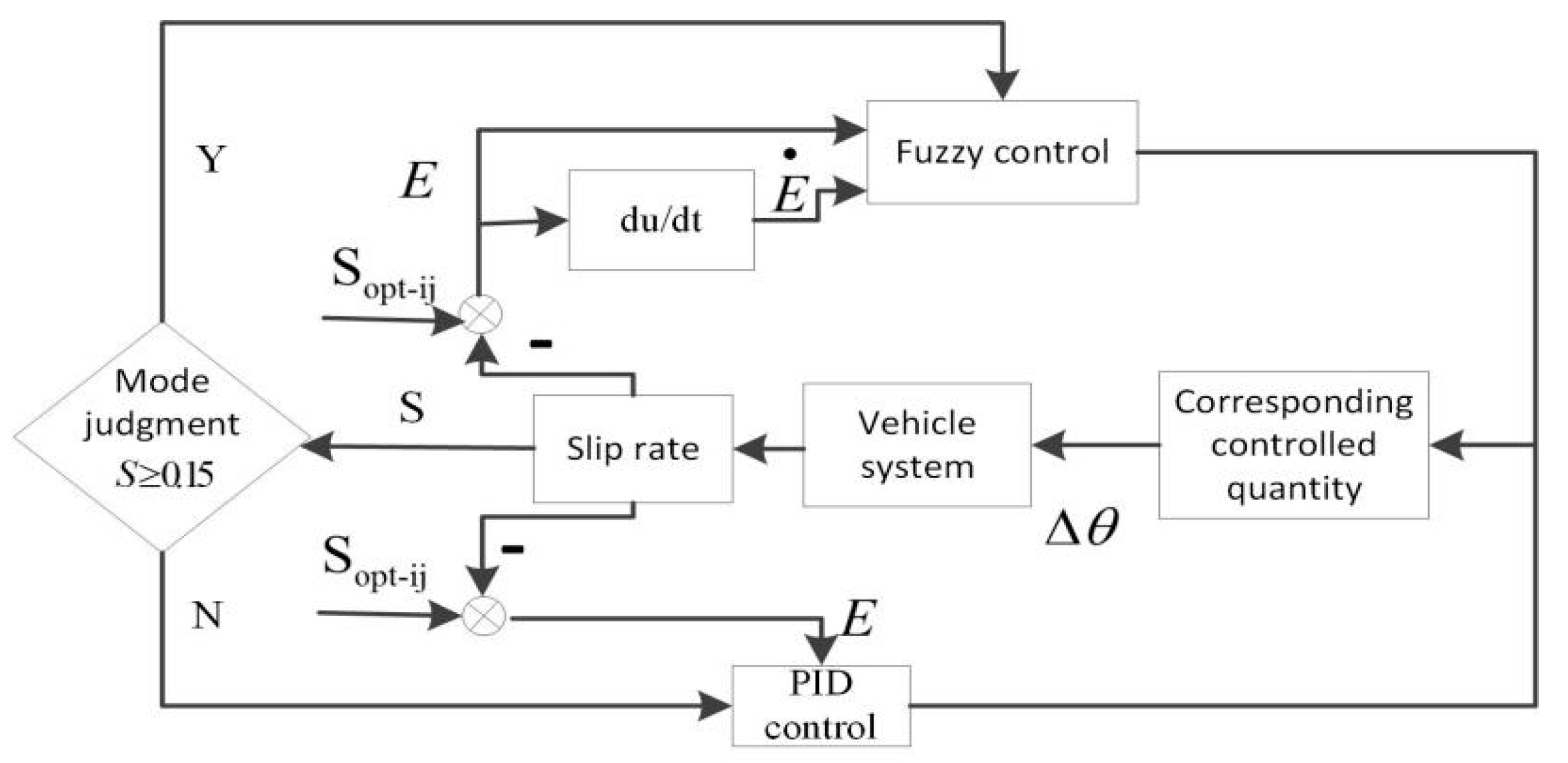
The slip rate control module consists of two modes, which has great flexibility. When the input error is large, fuzzy control is selected. Otherwise, the PID control strategy is chosen. A large number of experiments and studies have shown that when the slip rate is between 0.05 and 0.15, the overall stability of the vehicle is high, so 0.15 is selected as the reference value for the slip rate.
The fuzzy PID control slip rate control strategy is shown in Figure 7. The slip rate controller input of the road recognition module has obtained the optimal slip ratio and the real-time slip rate of the vehicle. The output signal is the driving torque of the hub motor. When the slip rate is 0.15, the vehicle is in good condition and has high stability without slippage. Therefore, the slip rate is 0.15 as the reference point. When the slip rate is greater than 0.15, fuzzy control is performed. The E input is the rate of change between the wheel’s real time slip rate and the optimal slip rate. The Output E ˙ is the corresponding control amount and the accelerator pedal adjustment amount Δ θ . When the slip ratio is less than 0.15, PID control is adopted. The difference E between the optimal slip rate output by the road surface recognition model and the real-time slip rate is used as the input of the PID controller. The output is the torque adjustment signal obtained by the adjustment amount of the accelerator pedal and the pedal signal, which drives the permanent magnet brushless DC hub motor.
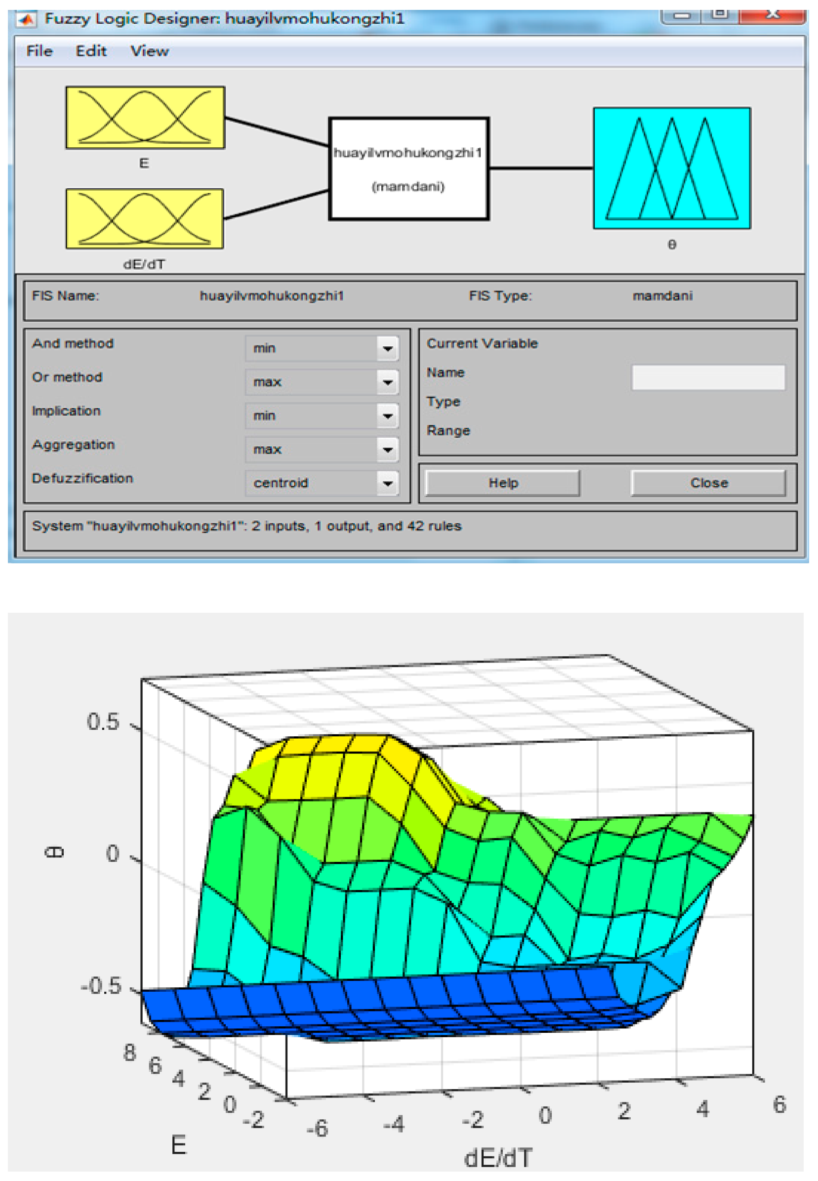
Fuzzy control rules are a vital part of fuzzy control. The rationality of fuzzy rules is directly related to the accuracy of control algorithms. Figure 8 is the output interface of the fuzzy controller with two inputs and one output of the slip rate module and the output surface of the fuzzy control pedal opening.
The rationality of the fuzzy rules is directly related to the accuracy of the control algorithm. Therefore, the effect of the slip rate of the motor torque is studied, and the fuzzy controller structure and variable domain theory are combined. Then, the fuzzy inference rules of slip rate controller are obtained.
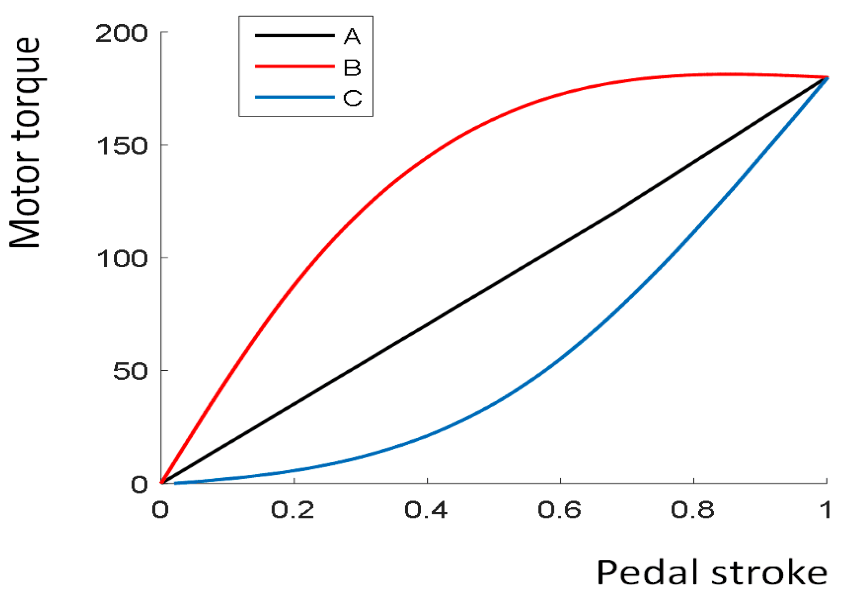
There is a certain functional relation among the four-wheel independent drive electric vehicle accelerator pedal acceleration signals of throttle opening, accelerator pedal opening signal, and the torque of the motor. Therefore, in the Simulink model, the motor needs to create a suitable throttle opening strategy for the torque control strategy. As shown in Figure 9, there are three forms of pedal and motor torque conversion. A is the pedal linear control strategy under ideal conditions, B is the soft pedal, and the control of the accelerator pedal from the upper half to the motor torque is sensitive. While the lower half is slow, C stands for hard pedal, opposite to the soft pedal control curve. The control from the pedal to the motor torque in the first half is relatively slow, while the control in the second half is more sensitive.
At present, the hard pedal represented by the C curve is widely used. Since the motor has no torque during the initial stroke of the accelerator pedal, it is a good idea to ignore the motor torque caused by the driver putting his foot on the accelerator pedal during driving. At the same time, the C curve response is relatively slow in the starting phase of the vehicle, which can filter out the jitter of the driver’s feet during the starting phase. In this paper, the C curve control strategy is selected, and the C curve is fitted using the trace method. The fitting function is as follows:
Y = 9.89 e 8 X 5 3.077 e + 0.003635 X 3 0.206 X 2 + 6.658 X + 14.42
where, Y is the motor torque (N.m); X is 100 times throttle opening.

4. The Simulation Analysis

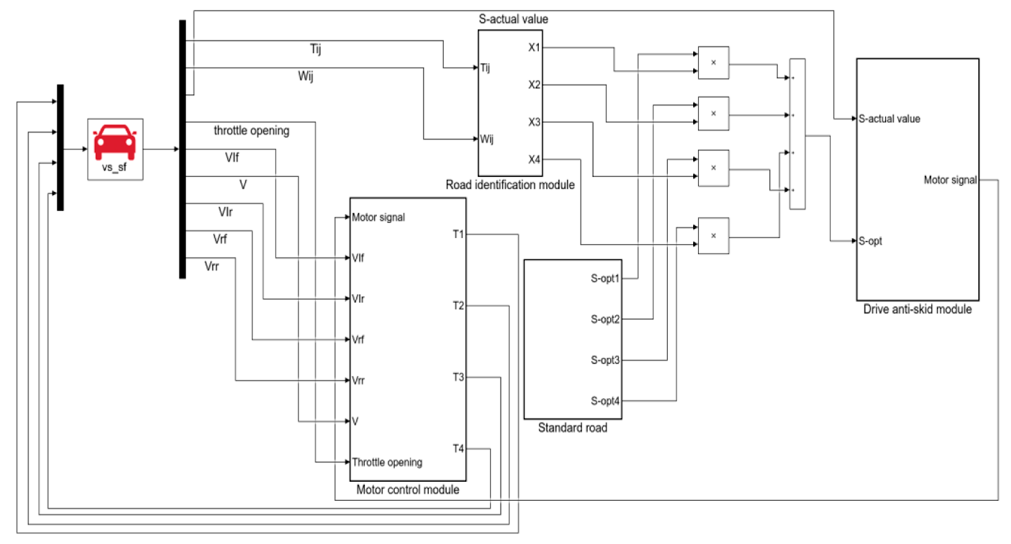
In order to verify the effectiveness of the driving anti-skid control strategy, a joint analysis was performed by using Carsim and MATLAB/Simulink. As shown in Figure 10, the road surface recognition module and the sliding speed control module were simulated and verified. In Carsim vehicle models, the appropriate vehicle model and corresponding vehicle body parameters are selected, including the basic parameters of the vehicle, the moment of inertia and the axial lateral stiffness, etc.
The vehicle parameters are set as follows: vehicle width is 1440 mm, center of mass height is 540 mm, vehicle mass is 1000 kg, front and rear wheelbase is 1860 mm, distance from center of mass to front axle is 1060 mm, distance from center of mass to rear axle is 1562 mm, front wheel radius is 330 mm, vehicle height is 1780 mm, rotation around x axis the inertia is 288 kg∙m2, the moment of inertia about the y-axis is 2031.4288 kg∙m2, the moment of inertia about the z-axis is 2031.4288 kg∙m2 and the radius of the rear axle is 330 mm.
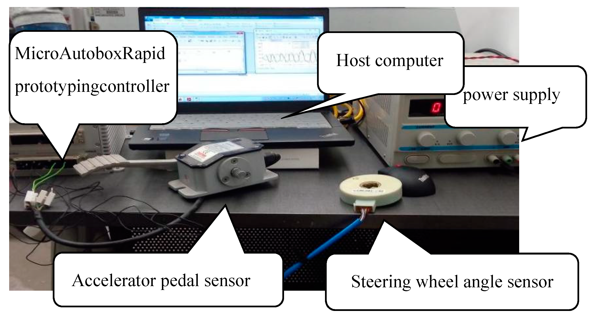
The establishment of a stability experiment platform based on dSPACE is shown in Figure 11. The experiment platform includes the MicroAutobox rapid prototype controller produced by dSPACE. As the hardware carrier of the control strategy, it also provides 5 V for the steering wheel angle sensor. It also provides 12 V for the controller and accelerator pedal. The host computer is a computer which mainly performs control strategy modeling, hardware code generation, and operation of the environmental test software ControlDesk. Sensors include accelerator pedal and steering wheel angle sensor; for pedal output the voltage range is 0~5 V, and the output voltage range of the steering wheel angle sensor is 0~10 V.

4.1. Road Recognition Module Verification

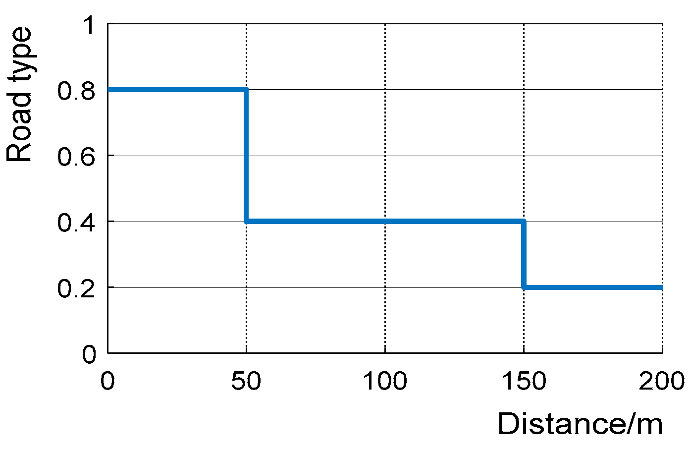
The key to the road surface recognition model is whether it can quickly recognize the type of road surface the current vehicle is driving on, and further determine the optimal slip rate of the current road surface. The initial speed of the four-wheel independent driving electric vehicle is 10 km/h, and the driving torque of each independent driving wheel is 500 N·m. The simulation verification of the docking road surface was performed, and the vehicle started to drive on a high-adhesion road surface for 50 m, then entered a medium-adhesion road surface to 150 m, and then entered a low-adhesion road surface until the end of the simulation experiment. Through the simulation experiments of docking road surface, the recognition capability of the road surface recognition module can be determined. The simulation results are shown in the following figure:
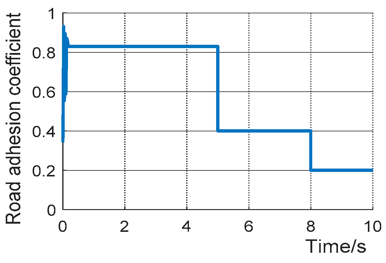
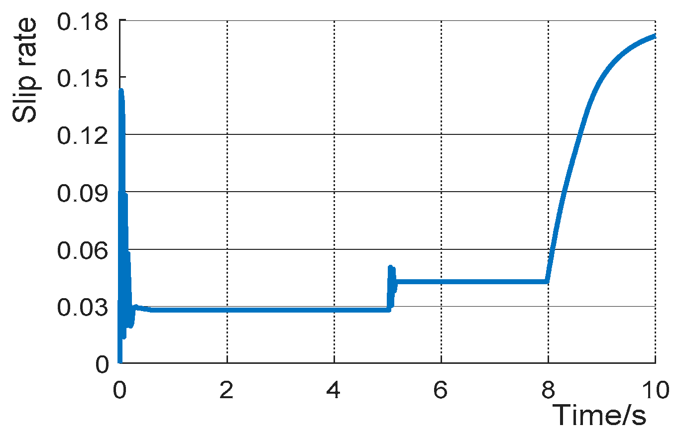
From Figure 12, Figure 13, Figure 14 and Figure 15, when the vehicle is driving on the docking road, it gradually changes from a high-adhesion road to a low-adhesion road. At the beginning of the vehicle, the slip rate and road adhesion coefficient fluctuate greatly, but it quickly enters the stable stage, and the road adhesion coefficient gradually decreases. The road adhesion coefficients are 0.82, 0.4 and 0.2. During 0–5 s, for vehicles on high-adhesion roads, the identified slip rate is about 0.135, the optimal slip rate identified in 5–8 s is about 0.098, and the best identified, in 8–10 s, is about 0.065; on high-adhesion roads, the actual slip rate of the vehicle is about 0.029, and the vehicle does not skid at all. On high-adhesion pavement, the pavement adhesion coefficient is large, and the slip rate does not change significantly. When the road surface adhesion coefficient is medium, the actual slip rate is about 0.047, and there is basically no slip. When the vehicle enters the low-adhesion road, the slip rate rises sharply, and the vehicle slips seriously. The entire road surface identification process is in line with the assumptions.
In summary, under different conditions of the road surface, the road surface recognition module can quickly recognize the current road surface condition and estimate the optimal slip rate of the current road surface. The recognition result conforms to the preset road surface law.

4.2. Slip Rate Control Module Verification

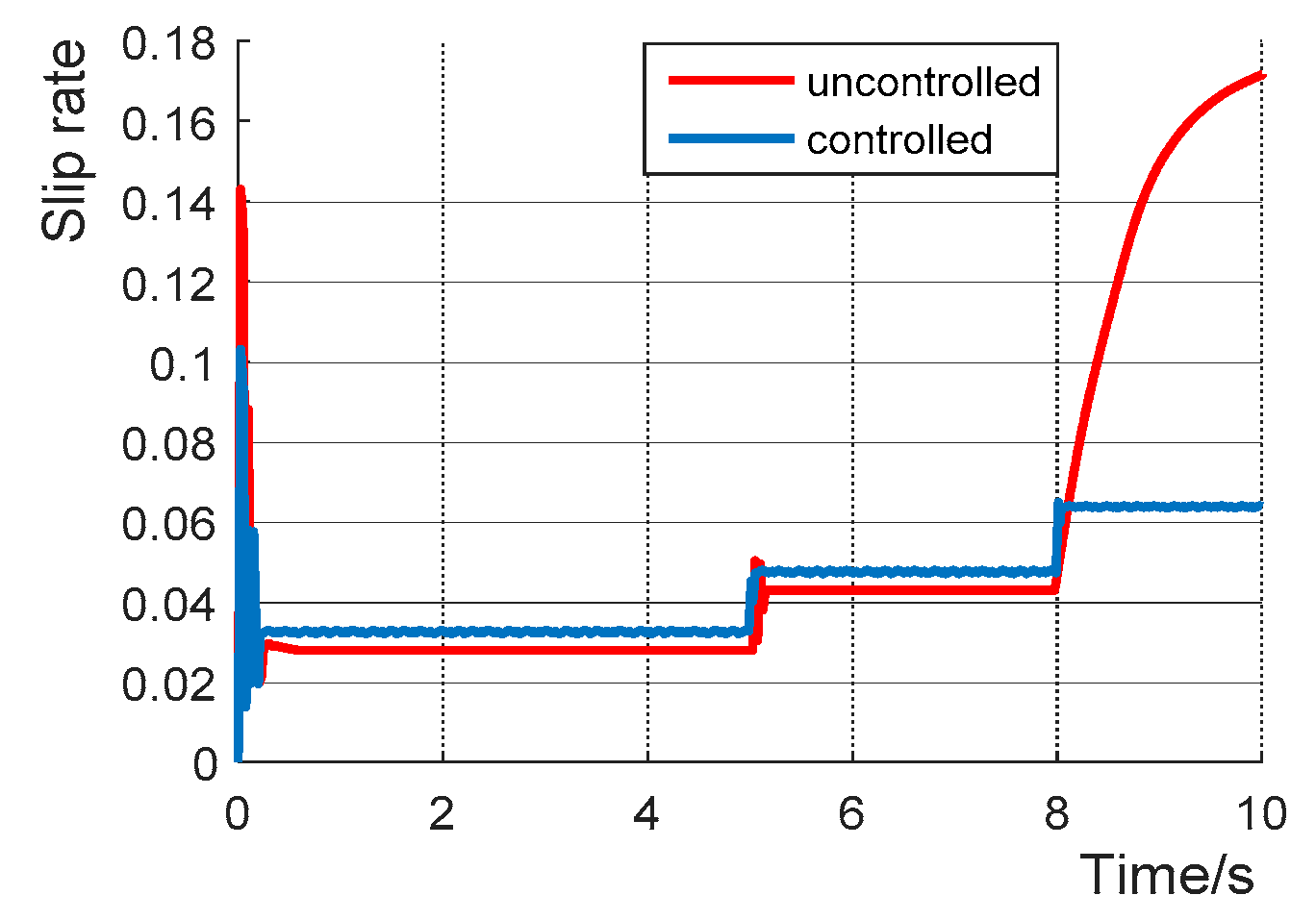
Based on the road surface recognition module’s estimation of the relevant parameters of the current road surface, the estimated value of the optimal slip ratio is obtained to adjust the driving torque in the slip rate control, and the actual slip ratio of the four-wheel independent drive electric vehicle is controlled in the optimal range. The road conditions are as follows: the vehicle starts to travel 50 m on the high-adhesion road, then joins the road to 150 m, and then enters the low-adhesion road until the end of the simulation experiment. The simulation results are shown below:
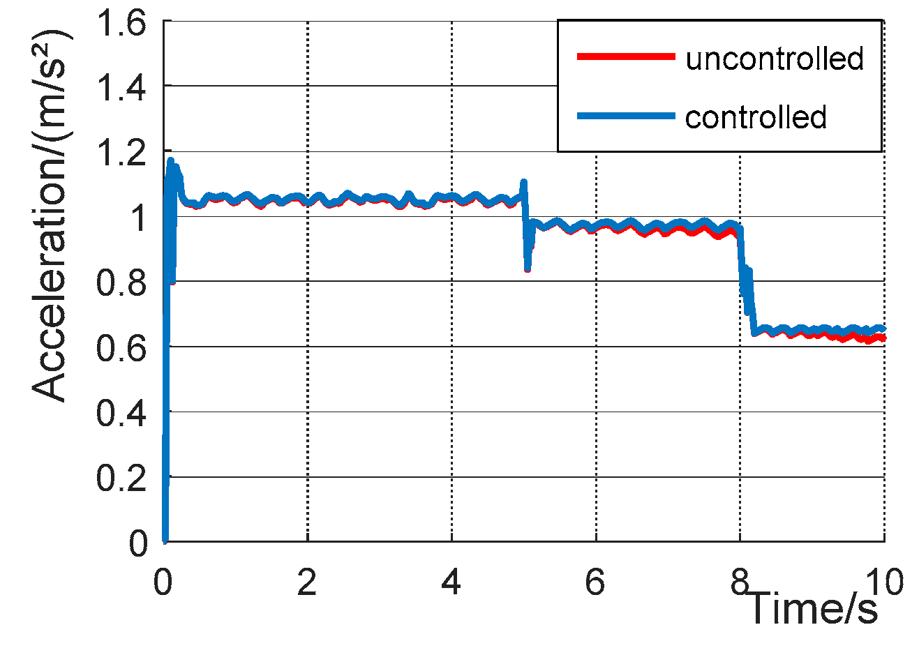
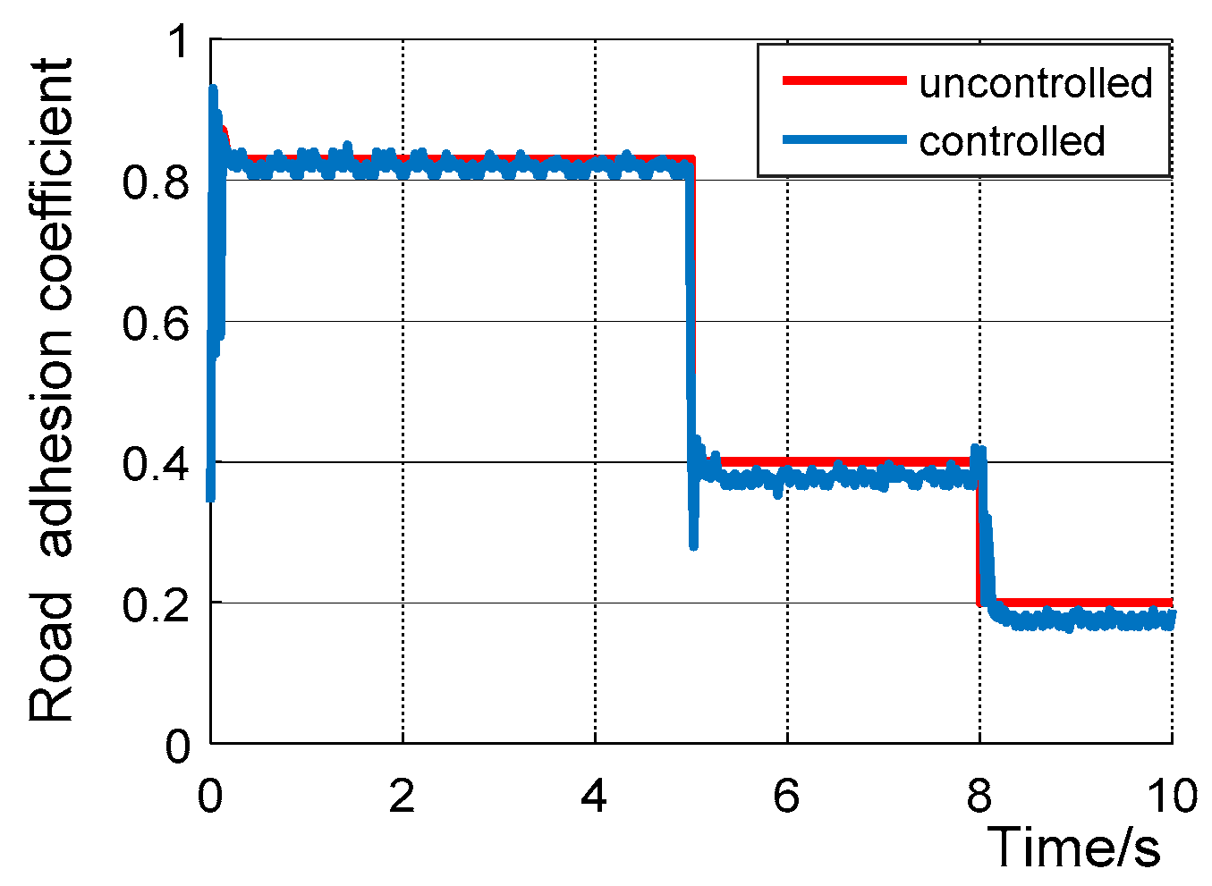
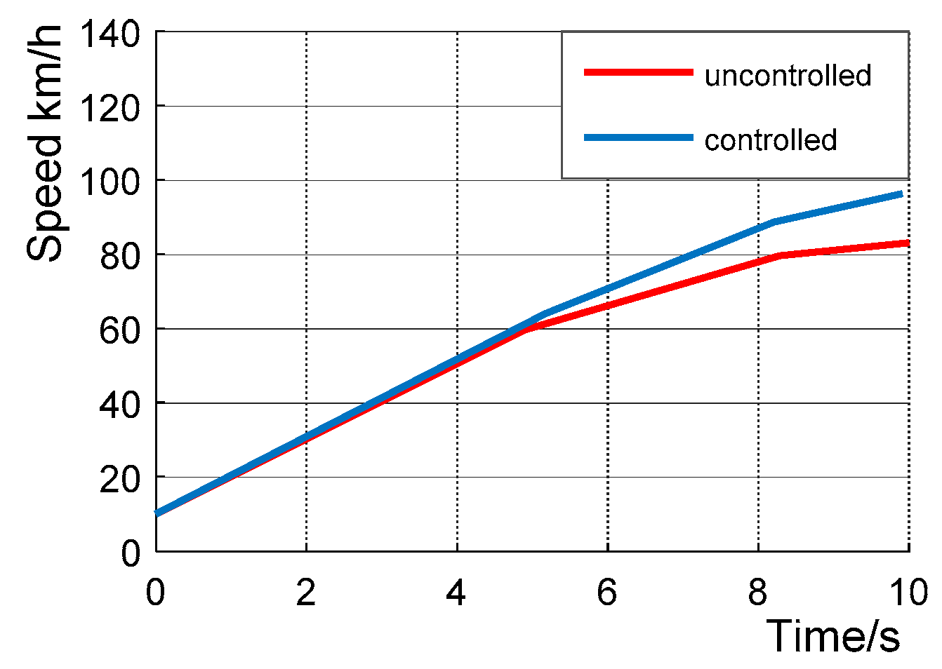
From Figure 16, Figure 17, Figure 18 and Figure 19, it can be seen that on high and medium viscosity roads, the driving torque and acceleration of the motor do not change. With a given road adhesion coefficient, the road surface adhesion coefficient remains basically unchanged, and the slip-rate control module does not work. When driving on a low-adhesion road, the motor torque does not change substantially without control, the vehicle seriously slips, the road surface adhesion coefficient is about 0.2, and the motor torque is drastically reduced when the slip ratio control module is operating. The acceleration and adhesion coefficient of the vehicle are also slightly reduced, and the vehicle slips, but all are within the optimal slip rate range.

5. Conclusions

This paper analyzes the domestic and foreign key technologies and existing problems of the four-wheel independent drive electric vehicle anti-skid control technology, then proposes a four-wheel independent drive electric vehicle anti-skid controller based on road recognition and finally carries out the control strategy simulation and experimental verification. The main conclusions are as follows:
(1)
The pavement recognition module establishes the standard pavement curve μ-s curve, and calculates the maximum adhesion coefficient of the pavement and the optimal slip rate when the vehicle is sliding.
(2)
The slip rate control module adopts a fuzzy PID control algorithm. The change rate of the difference between the real-time slip rate of the wheel and the target slip rate E and E is input, the torque adjustment signal is output, and the pedal signal is calculated and output to the wheel hub motor to further prevent the vehicle from slipping.
(3)
Carsim/Simulink software modeling is completed, and simulation verification of driving anti-skid controller is carried out. The results show that the road surface identification module in the driving anti-skid control strategy can quickly identify the current road surface conditions, and the slip rate control module can reasonably control the output motor driving torque, reasonably and effectively reduce the slip degree of the vehicle, and avoid the slip of the vehicle. Simulation results verify the feasibility of the control strategy. In the process of driving anti-skid, the standard road surface selected is not comprehensive enough and needs to be further optimized, so as to improve the efficiency and accuracy of road surface identification.

Author Contributions

Conceptualization, C.Z. and J.M.; methodology, C.Z. and J.M.; software, J.M.; validation, J.M., B.C. and J.W.; formal analysis, J.M.; investigation, C.Z.; resources, C.Z.; data curation, J.M.; writing—original draft preparation, J.M.; writing—review and editing, J.M. and B.C.; visualization, C.Z.; supervision, C.Z.; project administration, C.Z.; funding acquisition, C.Z. All authors have read and agreed to the published version of the manuscript.

Funding

This research was funded by the National Natural Science Foundation of China: Research on the Integrated Control Method of the Lateral Stability of Distributed Drive Mining Electric Vehicles (51974229). Project supported by the National Key Research and Development Program, China(No. 2018YFB1703402).And the 2021 Youth Innovation Team Construction Scientific Research Program of Shaanxi Provincial Education Department (21JP071).

Institutional Review Board Statement

Not applicable.

Informed Consent Statement

Not applicable.

Data Availability Statement

Not applicable.

Conflicts of Interest

The authors declare no conflict of interest.

References

  1. Yin, G.; Wang, R.; Wang, J. Robust control for four wheel independently-actuated electric ground vehicles by external yaw-moment generation. Int. J. Automot. Technol. 2015, 16, 839–847. [Google Scholar] [CrossRef]
  2. Alipour, H.; Sabahi, M.; Sharifian, M.B.B. Lateral stabilization of a four wheel independent drive electric vehicle on slippery roads. Mechatronics 2015, 30, 275–285. [Google Scholar] [CrossRef]
  3. Ma, C.; Xu, M.; Wang, H. Wang Dynamic emulation of road/tyre longitudinal interaction for developing electric vehicle control systems. Veh. Syst. Dyn. 2011, 49, 433–447. [Google Scholar] [CrossRef]
  4. Shuai, Z.; Zhang, H.; Wang, J.; Li, J.; Ouyang, M. Lateral motion control for four-wheel-independent-drive electric vehicles using optimal torque allocation and dynamic message priority scheduling. Control Eng. Pract. 2014, 24, 55–66. [Google Scholar] [CrossRef]
  5. Zhang, H.; Zhang, X.; Wang, J. Robust gain-scheduling energy-to-peak control of vehicle lateral dynamics stabilization. Veh. Syst. Dyn. 2014, 52, 309–341. [Google Scholar] [CrossRef]
  6. Liu, X.; Li, M.; Xu, M. A new anti-skid control method for electric vehicles using the motor torque and the wheel acceleration with experimental verification. Proc. Inst. Mech. Eng. Part D J. Automob. Eng. 2016, 231, 347–359. [Google Scholar] [CrossRef]
  7. Zheng, L. Analysis of the Lateral Stability for Four-wheel Independent Driving Electric Vehicles. In Proceedings of the 2014 International Conference on Applied Mechanics and Mechanical Automation (AMMA 2014), Macau, China, 20–21 May 2014; Science and Engineering Research Center: Macau, China, 2014; Volume 590, pp. 394–398. [Google Scholar]
  8. He, H.; Peng, J.; Xiong, R.; Fan, H. An Acceleration Slip Regulation Strategy for Four-Wheel Drive Electric Vehicles Based on Sliding Mode Control. Energies 2014, 7, 3748–3763. [Google Scholar] [CrossRef] [Green Version]
  9. Liang, Z. Design and Research of Electric Vehicle Wheel Rim Four-Wheel Drive System; Zhejiang University: Hangzhou, China, 2018. [Google Scholar]
  10. Zhang, T. Research on Driving Anti-Skid Control of Distributed Driven Electric Vehicles; Nanjing University of Science and Technology: Nanjing, China, 2017. [Google Scholar]
  11. Sakai, S.-I.; Sado, H.; Hori, Y. Anti-skid control with motor in electric vehicle. In Proceedings of the International Workshop on Advanced Motion Control, Nagoya, Japan, 30 March–1 April 2000; pp. 317–322. [Google Scholar]
  12. Economou, J.T.; Colyer, R.E. Fuzzy-hybrid modelling of an Ackerman steered electric vehicle. Int. J. Approx. Reason. 2006, 41, 343–368. [Google Scholar] [CrossRef] [Green Version]
  13. Vasiljevic, G.; Griparic, K.; Bogdan, S. Experimental testing of a traction control system with on-line road condition estimation for electric vehicles. In Proceedings of the 21st Mediterranean Conference on Control and Automation, Platanias, Greece, 25–28 June 2013. [Google Scholar]
  14. Zhang, L.; Li, L.; Qi, B.; Song, J.; Xu, H. Torque adaptive drive anti-skid control for distributed drive electric vehicles. J. Mech. Eng. 2013, 49, 106–113. (In Chinese) [Google Scholar] [CrossRef]
  15. Li, J.; Su, Y.; Kui, H. Research on Driving Anti-skid Control Strategy of Four-wheel Drive Hybrid Electric Vehicle. Automot. Eng. 2017, 39, 296–303. (In Chinese) [Google Scholar]
  16. Huang, L.; Wang, W.; He, Z. Research on integrated control strategy of electric vehicle direct yaw moment and driving anti-skid. Automot. Technol. 2019, 6, 41–46. (In Chinese) [Google Scholar]
  17. Wang, Z.; Zhou, Y.; Lee, G. The Sliding Mode Control about ASR of Vehicle with Four Independently Driven In-Wheel Motors Based on the Exponent Approach Law. Energy Procedia 2016, 88, 827–832. [Google Scholar] [CrossRef] [Green Version]
  18. Wang, H.-L.; Shi, Z.-K. Vehicle dynamics model and safety analysis on mountainous road. Control Theory Appl. 2015, 32, 837–843. [Google Scholar]
  19. Yu, Z.; Wang, G.; Xiong, L.; Leng, B. Analysis of anti-skid control effect of driving electric bus with distributed drive. Automot. Technol. 2016, 3, 18–25. (In Chinese) [Google Scholar]
  20. Liu, W.; He, H.; Peng, J. Driving Control Research for Longitudinal Dynamics of Electric Vehicles with Independently Driven Front and Rear Wheels. Math. Probl. Eng. 2013, 2013, 408965. [Google Scholar] [CrossRef]
Figure 1. Car dynamics model diagram.
Wevj 12 00150 g001
Figure 2. Wheel dynamics model.
Wevj 12 00150 g002
Figure 3. Working process of driving anti-skid system.
Wevj 12 00150 g003
Figure 4. Relationship between adhesion coefficient and slip rate.
Wevj 12 00150 g004
Figure 5. Road recognition principle.
Wevj 12 00150 g005
Figure 6. Fuzzy controller for road surface recognition.
Wevj 12 00150 g006
Figure 7. Block diagram of compound PID control with slip rate control.
Wevj 12 00150 g007
Figure 8. Road surface recognition control output surface.
Wevj 12 00150 g008
Figure 9. Function relation of accelerator pedal opening and motor torque.
Wevj 12 00150 g009
Figure 10. Simulation model of driving anti-skid control strategy.
Wevj 12 00150 g010
Figure 11. Stability experiment platform based on dSPACE.
Wevj 12 00150 g011
Figure 12. Road type curve.
Wevj 12 00150 g012
Figure 13. Road adhesion curve.
Wevj 12 00150 g013
Figure 14. The actual slip rate curve.
Wevj 12 00150 g014
Figure 15. The optimal slip rate curve.
Wevj 12 00150 g015
Figure 16. Slip rate curve.
Wevj 12 00150 g016
Figure 17. Acceleration curve.
Wevj 12 00150 g017
Figure 18. Road adhesion coefficient curve.
Wevj 12 00150 g018
Figure 19. Speed curve.
Wevj 12 00150 g019
Table 1. Parameter values of four typical roads.
Parameter
Road Type
Dry AsphaltWet AsphaltSnow PavementIce Pavement
C11.28010.8570.19460.05
C223.9933.82294.129306.39
C30.520.34700.06460.001
Sopt0.1700.1310.0650.03
μmax1.1710.80.1900.05
Table 2. Fuzzy control rules for road surface recognition.
Adhesion Coefficient
Slip Rate
Dry Asphalt
S
Wet Asphalt
M
Snow Pavement
B
Ice Pavement
VB
Dry asphalt HESDTDTD
Wet asphalt MGSESTDTD
Snow pavement LTDTDESD
Ice pavement VLTDTDGSES
Publisher’s Note: MDPI stays neutral with regard to jurisdictional claims in published maps and institutional affiliations.