Article

Multi-Objective Optimization Design of Permanent Magnet Torque Motor

School of Electrical Engineering and Automation, Harbin Institute of Technology, Harbin 150001, China
*
Author to whom correspondence should be addressed.
World Electr. Veh. J. 2021, 12(3), 131; https://doi.org/10.3390/wevj12030131
Submission received: 15 July 2021 / Revised: 13 August 2021 / Accepted: 17 August 2021 / Published: 22 August 2021

Abstract

:
Permanent magnet torque motor (PMTM) is widely used in aerospace, computer numerical control (CNC) machine tools, and industrial robots with many advantages such as high torque density, strong overload capacity, and low torque ripple. With the upgrading of industrial manufacturing, the requirements for the performance of torque motors have become more stringent. At present, how to achieve high output torque and low torque ripple has become a research hotspot of torque motors. In the optimization process, it is necessary to increase the output torque while the torque ripple can be reduced, and it is difficult to get a good result with the single-objective optimization. In this paper, a multi-objective optimization method based on the combination of design parameter stratification and support vector machine (SVM) is proposed. By analyzing the causes of torque ripple, the output torque, efficiency, cogging torque, and total harmonic distortion (THD) of back electromotive force (EMF) are selected as the optimization objectives. In order to solve the coupling problem between the motor parameters, the calculation formula of Pearson correlation coefficient is used to analyze the relationship between the design parameters and the optimization objectives, and the design parameters are layered ac-cording to the sensitivity. In order to shorten the optimization cycle of the motor, SVM is used as a fitting method of the mathematical model. The performance between initial and optimal motors is compared, and it can be found that the optimized motor has a higher torque and lower torque ripple. The simulation results verify the effectiveness of the proposed optimization method.

1. Introduction

With the in-depth research of permanent magnet materials, permanent magnet materials with excellent performance have been invented, which can improve the performance of permanent magnet motors [1]. In order to improve the performance of the motor, researchers have done a lot of research work. One type of method is to improve the topology of motors, such as: skewed slot [2], fractional slot winding [3], offset asymmetric rotor poles [4], etc. Another type of method is to improve the design parameters of motors through optimization methods to achieve the purpose of improving the electromagnetic performance of motors. Motor optimization is an important research topic in the field of motors. Because the traditional single-objective optimization method cannot meet the needs of motor optimization, researchers have explored the optimization method of the motor for many years. At present, the multi-objective optimization method of motors is widely used in the field of motor optimization. Taguchi method is proposed by a Japanese quality control expert, and this method is an optimization method based on orthogonal experiment and signal to noise ratio [5,6]. Taguchi method is used to select the best combination of design parameters to improve the electromagnetic performance of motors [7,8,9]. With the development of artificial intelligence, researchers have gradually introduced optimization algorithms such as genetic algorithm, particle swarm algorithm, and bee colony algorithm into process of motor optimization [10,11,12,13], and these algorithms have a better search ability than Taguchi.
In the process of motor optimization, a mathematical model needs to be used. This model is used to describe the relationship between the optimization objective and the design parameters, and it is taken as the optimization objective function. The finite element model is generally used, and the development of finite element software in the field of motor design is becoming mature, such as Maxwell, Motor CAD, Flux, etc. These software integrate intelligent optimization algorithms such as particle swarm algorithm and genetic algorithm, which can be directly called during the motor optimization process [14]. However, finite element simulation needs to consume a lot of simulation time, and with the increase of motor design parameters, the time consumed increases exponentially. Some researchers used response surface model instead of finite element model, and have achieved certain results [15,16,17,18], but the number of design parameters that can be fitted by response surface method is relatively small. There are many design parameters in PMTM, and the coupling relationship between design parameters and optimization objectives also increases the difficulty of motor optimization.
To solve these problems, a multi-objective optimization method based on the combination of design parameter stratification and support vector machine (SVM) is proposed. Different design parameters have different sensitivities for different optimization objectives. It is unreasonable to fit the mathematical model without distinguishing the design parameters, which can increase the simulation time and reduce the accuracy of the model [19,20]. In this paper, idea of design parameter stratification is introduced, and the sensitivity of each design parameter to different optimization objectives is calculated. The design parameters are divided into different levels according to the sensitivity. SVM is introduced into the fitting process of the mathematical model, and the mathematical model obtained by the SVM is used to replace the finite element model to complete the subsequent motor optimization, which can shorten the simulation time and the motor optimization cycle. SVM is an intelligent algorithm based on statistics and the principle of structural risk minimization [21,22]. Because of its kernel function, SVM has a strong nonlinear fitting ability. The relationship between motor design parameters and optimization objectives is non-linear, and SVM can be used to solve this problem. By using SVM, a relatively accurate mathematical model can be quickly obtained. The particle swarm algorithm has a strong ability to find optimization, fewer parameters need to be adjusted, and the algorithm converges quickly, so it is widely used in various optimization fields, and particle swarm will be used as the search algorithm [23,24].
In this paper, in order to reduce the torque ripple of the torque motor and shorten the optimization cycle of the motor, this paper proposes a multi-objective optimization method. After determining the optimization objectives, first, the Pearson correlation coefficient calculation formula is used to obtain the sensitivity of each parameter to the optimization objectives, and design parameters are classified. Then, the optimization based on SVM and FEA is completed. The simulation results verify that the optimization method can improve torque performance of PMTM, and the optimized motor performance can meet engineering needs.

2. Materials and Methods

2.1. Determination of Optimization Objectives

2.1.1. Structure of the PMTM

The design of motor is the premise of motor optimization. By comparing performance of different poles and slots, the number of poles and slots of the motor are finally determined to be 16 and 18. The model structure of the PMTM proposed in this paper is shown in Figure 1. In order to reduce torque ripple, bread-shaped magnetic pole and concentrated fractional slot windings are adopted in the motor. According to relative theory and experience of motor design, the design of the PMTM is completed. The design parameters and initial dimensions of the PMTM are shown in the Table 1.

2.1.2. Analysis of Torque Ripple

Torque ripple is an important factor that affects control accuracy of servo systems, and it is also easy to cause permanent magnet motor vibration and mechanical noise. If the situation is serious, it will affect the reliability of the motor. Smooth motor torque is required for most applications. Suppression of torque ripple is an important content in the design of high-precision permanent magnet motor. The motor torque ripple is shown as [25]:
T r i p = T max T min T a v g × 100 %
where Trip is motor torque ripple, Tavg is the average value of output torque, Tmax the maximum value of output torque, Tmin is the minimum value of output torque. Due to problems of meshing, the finite element software has the problem of non-convergence of a certain unit, which can cause inaccurate measurements of the maximum or minimum value. Therefore, it is necessary to analyze the cause of motor torque ripple and find out the substitute index of torque ripple. The torque formulas in permanent mag-net motor are as follows [26]:
{ T = T c o g + T e m T e m = N p ( ψ d i q ψ q i d ) = N p [ ( ψ f d i q ψ f q i d ) + ( L d L q ) i d i q ] T p m = N p ( ψ f d i q ψ f q i d ) T r = N p ( L d L q ) i d i q
where T is output torque of the motor, Tcog is cogging torque, Tem is electromagnetic torque. Np is the number of pole pairs of the motor, Tpm is permanent magnet torque, Tr is reluctance torque. After the above analysis, it is easy to know that torque ripple is related to cogging torque, harmonics of permanent magnets, and reluctance torque.
Because the research object of this paper is a surface mount motor, its reluctance torque can be ignored, and THD of no-load back EMF can reflect the sine of the magnetic density waveform. In summary, output torque, THD of no-load back EMF, and cogging torque are selected as optimization objectives in the optimization of the PMTM. By optimizing the design parameters, these objectives are improved, and the purpose of improving the torque performance of the motor can be achieved.

2.2. Multi-Objective Optimization

2.2.1. Sensitive Analysis

As mentioned above, there are many design parameters in the PMTM. The sensitivity of each design parameter to different optimization objectives is different. When the number of design parameters is too large, the accuracy of the surrogate model can be decreased. In order to analyze the relationship between design parameters and optimization objectives, this paper uses orthogonal experiments to obtain data, and the Pearson correlational coefficient is used to perform the sensitivity analysis [19,20]. It can be calculated as:
ρ Y i , X i = N Y i X i Y i X i N Y i 2 ( Q i ) 2 N X i 2 ( X i ) 2
where Yi is the ith optimization objective, Xi is the design parameters, and N is sample size.
Thus, the sensitivity of each parameter to the objectives is shown in 
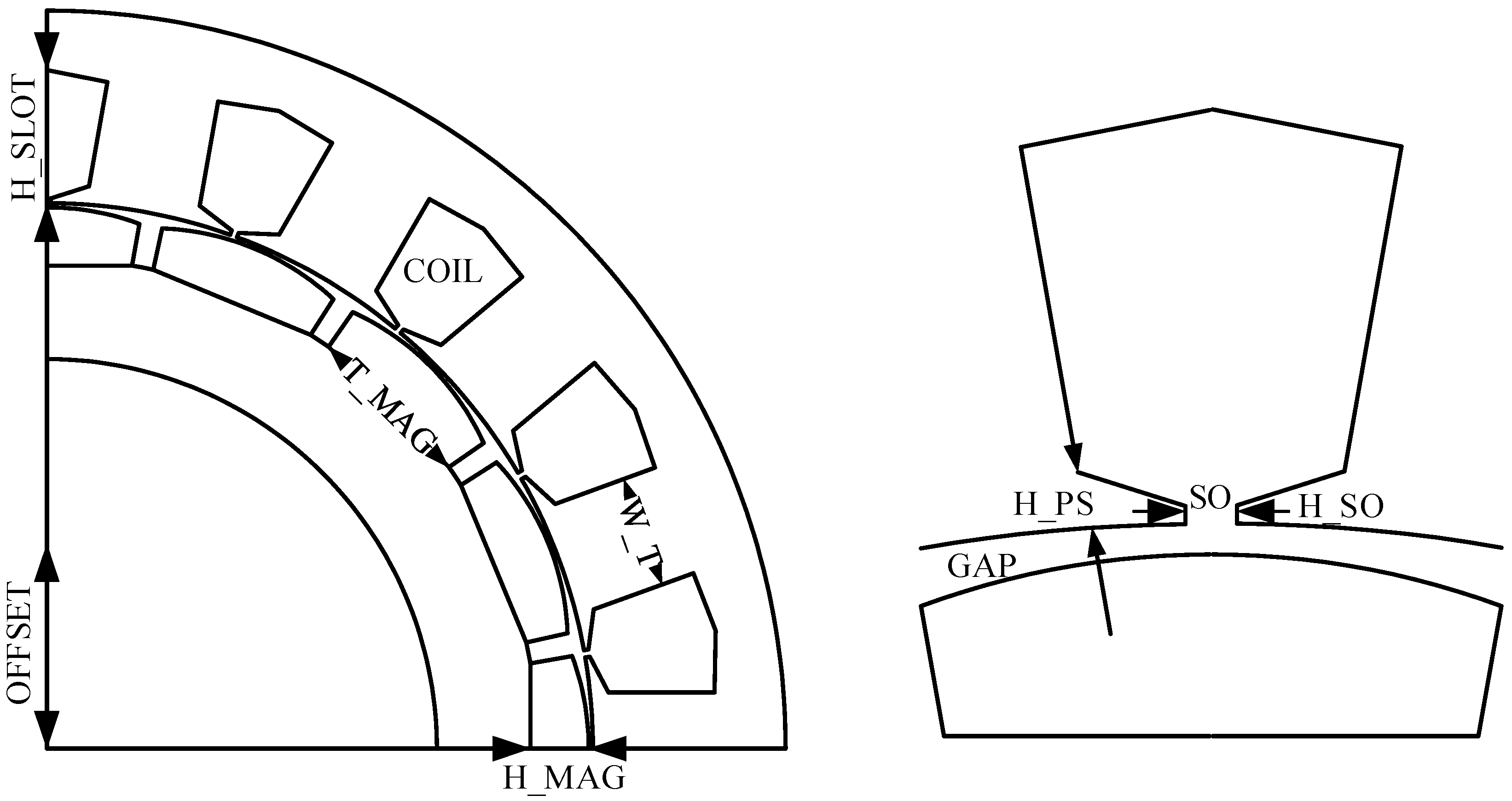
Figure 2. It can be noted that the sensitivity of each parameter to the objectives varies greatly, and T_MAG, GAP, H_MAG, W_T, and COIL have great influence on torque and effectiveness. SO, H_PS, OFFSET, and H_SO have little influence on torque and effectiveness, but they are sensitive to Cogging and THD.
According to the different sensitivities of design parameters to the optimization objectives, the design parameters are divided into two levels, as shown in the following Table 2 and Table 3. The design parameters can be divided into different levels according to the sensitivity of the parameters to the optimization objectives. Because the primary requirement for the motor is to ensure the output torque, the optimized parameters in the first level are sensitive to efficiency and output torque. The parameters of the second level are sensitive to cogging torque and THD. The reason for this arrangement is also that the accuracy of the surrogate model of cogging torque and THD is slightly lower. In the second-level optimization, model is not used, and the finite element method is used to obtain the relationship between the optimization objective and the parameters. Thus, a double level optimization method is proposed in this paper, and the flowchart of the multi-objective optimization is shown in Figure 3.

2.2.2. Optimization of First Level

Motor optimization is a non-linear problem. There is a non-linear relationship between design parameters and motor performance. Traditional statistical methods cannot guarantee the accuracy of the proxy model. In this paper, SVM is introduced for the optimization of PMTM, and the model can be obtained by SVM.
The initial application of SVM is in the field of sample classification. When some sample points cannot be linearly separated in low-dimensional space, they are mapped to high-dimensional space through a kernel function to achieve the purpose of linear separability of samples. Due to the kernel function, SVM has a strong data-fitting ability. In the paper, SVM is used to fit the data and the relationship between the design parameters and the optimization objective can be obtained. The SVM formula is expressed as [25]:
f ( x ) = i = 1 n ω i K ( x i , x ) + b *
where ωi is the regression parameter vector, K(x) is kernel function. n is the number of support vector, xi is support vector, x is predicted vector, b* is the Bias factor. The structure of SVM is shown in Figure 4.
The core of the SVM is the kernel function, and the main types of kernel functions of SVM are linear kernel function, polynomial kernel function, Gaussian radial basis kernel function, exponential radial basis kernel function, and multilayer perceptron kernel function respectively, which are shown as [27]:
{ K ( x i , x ) = x T x i K ( x i , x ) = ( x T x i + r ) p K ( x i , x ) = exp ( x x i 2 σ 2 ) K ( x i , x ) = exp ( x x i σ 2 ) K ( x i , x ) = tanh ( γ x T x i + r )
where p, r, γ, and σ are the parameters of kernel function. The Gaussian radial basis kernel function has the best generalization performance, so in this paper it is selected as the kernel function in SVM.
The parameters of first level are sensitive to torque and efficiency, and some of the parameters such as length of air gap, has an influence on cogging and THD. For these parameters, the mathematical model can be obtained by using SVM. First, orthogonal experiment is used for the complete collection of sample data of training set, and then SVM is used to obtain SVM model of the optimization objectives, which can be represented as:
{ T r a t e d ( x ) = i = 1 n ω i _ Trated K ( x i , x ) + b * Trated E f f i c i e n c y ( x ) = i = 1 n ω i _ E f f i c i e n c y K ( x i , x ) + b * E f f i c i e n c y THD ( x ) = i = 1 n ω i _ THD K ( x i , x ) + b * THD Cogging ( x ) = i = 1 n ω i _ Cogging K ( x i , x ) + b * Cogging
where x is the parameter of the first level, Trated(x) is output torque of the SVM model, Efficiency(x) is the efficiency of the SVM model, THD(x) is the THD of back EMF SVM model, and Cogging(x) is the cogging torque of the SVM model.
After obtaining the SVM model, the usability of the model needs to be verified. The finite element method is used to obtain 15 sets of test data, which are compared with the data of the SVM model, and the 15 sets of data are shown in Table 4.
The formula of mean square error and determining factor is expressed as:
{ M S E = 1 l i = 1 l ( y ^ i y i ) 2 R 2 = ( l i = 1 l y ^ i y i i = 1 l y ^ i i = 1 l y i ) 2 ( l i = 1 l y ^ i 2 ( i = 1 l y ^ i ) 2 ) ( l i = 1 l y i 2 ( i = 1 l y i ) 2 )
where MSE is the mean square error, R2 is the determining factor, l is the number of samples in the test set, y i is the true value of the ith sample, and y ^ i is the predicted value of the ith sample. The value of MSE and R2 can be used to judge the accuracy of SVM models. According to the above formula, MSE and R2 can be calculated and be shown in the following Table 5.
It can be seen from the data in the table that the accuracy of SVM model of output torque and efficiency is very high, these SVM models are almost consistent with the finite element models. However, the accuracy of SVM model of THD and cogging torque is relatively poor. Due to the existence of slots, the change trend of the air gap permeability can become more diverse, and the high-precision model cannot be fitted when the amount of data is insufficient.
The data of the finite element model is compared with the data of the SVM model, and the results are shown in Figure 5, Figure 6, Figure 7 and Figure 8. The x-axis in these figures is the serial number of 15 sets of data. It can be noted that there are differences between the finite element model and the SVM model in individual values, but the trend of the predicted value is consistent with the trend of the actual value. In engineering, the values of optimization objective serve as a reference, and the design parameters are focused on, so these models are available. In this paper, the parameters that have a strong influence on cogging torque and THD, but the parameters that have little influence on torque and efficiency are placed in the optimization of the second level.
After getting four SVM models, according to the actual needs of performance, a multi-objective optimization mathematical model can be established, and can be represented as:
{ max F ( X ) = ( f 1 ( X ) , f 2 ( X ) , f 3 ( X ) ) X R n f 1 ( X ) = Trated ( X ) f 2 ( X ) = 1 THD ( X ) f 3 ( X ) = 1 Cogging ( X ) f 4 ( X ) = Efficiency ( X ) s . t . Trated ( X ) > 38 Efficiency ( X ) > 82 THD ( X ) < 1.7 Cogging < 250
where X is the parameter, f1(X) is the fitness function of torque, f2(X) is the fitness function of cogging torque, f3(X) is the fitness function of THD, f4(X) is the fitness function of efficiency. Trated(X), THD(X), Cogging(X), and Efficiency(X) are the SVM model of four optimization objectives respectively.
In this paper, particle swarm algorithm is used to optimize the multi-objective optimization mathematical model. The PSO algorithm is expressed as follows:
{ v i k + 1 = ω v i k + c 1 r 1 ( p i k x i k ) + c 2 r 2 ( p g k x i k ) x i k + 1 = x i k + v i k + 1 ω = ω max k ( ω max ω min ) k max
where ω is the weight of inertia, c1 and c2 are self-learning factor and social learning factor, r1 and r2 are two random numbers respectively, ωmax and ωmin are the maximum and minimum values of the inertia weight respectively, k and kmax are the current number of iterations and maximum number of iterations respectively.
In the particle swarm algorithm, the inertia weight is a quantity that reflects the inheritance of the particle to the velocity. Although the convergence speed of ordinary particle swarm algorithm is fast, it is easy to fall into the local optimum. Changing the value of the inertia weight in the iterative process is beneficial to improve the optimization ability of the algorithm. In the improved particle swarm algorithm, the maximum and minimum inertia weights are introduced to achieve the above effects. In the early iteration of the algorithm, the inertia weight is larger, and the particle speed of the particle swarm is faster, so the algorithm’s global search ability is stronger. The inertia weight is higher in the later iteration of the algorithm, and the particle speed of the particle swarm is slower, so the local search ability of the algorithm is stronger. It balances the global search and local search in the process of the whole algorithm, and the values of the relevant parameters of the particle swarm are shown in the following Table 6.
According to obtaining the multi-objective model and the search algorithm, the program of motor optimization of the first level can be written. The pareto front of the multi-objective optimization is obtained, as is shown in Figure 9. According to the requirements and processing conditions, the values of the parameters of the first level are determined. The optimization result of first level is shown in Table 7.

2.2.3. Optimization of Second Level

After finishing optimization of the first level, parameters of the first level are kept unchanged and the second level optimization is carried out. The parameters of second level have little influence on torque and efficiency, but they are sensitive to cogging torque and THD. The finite element method is used to obtain the relationship curve between the optimization objective and the design parameters, as shown in Figure 10.
Both THD and cogging torque have an optimal value in the optimization process of H_PS, so H_PS is selected as 2 mm. H_SO and SO are taken at the minimum value of THD curve, and H_SO and SO are determined to be 0.5 mm and 0.75 mm respectively. If the OFFSET is too large, the magnetic flux density will be affected. When OFFSET is 40 mm, the output torque is lower than the requirements of technical index, so OFFSET is selected as 30 mm. The optimization result of second level is shown in the Table 8.

3. Results

Through the above optimization method, the multi-objective optimization of output torque and torque ripple is completed. The optimized performance is compared with the initial motor performance, as shown in Figure 11, Figure 12 and Figure 13.
Figure 11 shows the comparison of the amplitude of the no-load back EMF before and after the optimization. It can be noted that the fundamental wave amplitude is increased from 190.4 V to 194.5 V, which is beneficial to increase output torque of the PMTM. After optimization, the THD is decreased from 2.06% to 1.02%, which proves that the sine of the air gap flux density is improved. It is beneficial to reduce the torque ripple when the motor is running under load. Figure 12 shows the comparison of the cogging torque before and after the optimization, and cogging torque of the PMTM is reduced from initial 313 mN·m to 165 mN·m. Cogging torque is one of the main causes of torque ripple, so reducing the cogging torque of the motor also helps to reduce the torque ripple of the motor. Figure 13 shows the waveform of output torque of the motor before and after the optimization. Torque ripple of the motor is reduced from 3.7% to 1.7%, and output torque is increased from 38 N·m to 40.2 N·m, which proves the rationality of the above optimization.

4. Conclusions

This paper proposes a multi-objective optimization method based on the combination of design parameter stratification and SVM. The effectiveness of the proposed optimization method is proved by simulation. The main conclusions are the following:
(1)
Through the analysis of the causes of torque ripple, the optimization objectives are determined. The simulation results show that the optimization of THD and cogging torque is helpful to reduce torque ripple and improve torque performance of the motor.
(2)
Aiming at the coupling problem between parameters and performance of motor, the Pearson formula is used to calculate the sensitivity of the design parameters for the optimization objectives. The design parameters are divided into two levels, which can achieve decoupling to a certain extent.
(3)
Aiming at the long time-consuming problem of finite element simulation, SVM is used to fit mathematical models which can replace the finite element models. The models can have high accuracy and meet engineering needs.
(4)
Compared with the initial design, the output torque of the motor becomes larger and the torque ripple becomes smaller, which can prove the effective-ness of the proposed method.

Author Contributions

Conceptualization, J.C., T.Z. and X.G.; methodology, J.C.; software, J.C.; writing—original draft preparation, J.C. and T.Z.; writing—review and editing, T.Z. and X.G. All authors have read and agreed to the published version of the manuscript.

Funding

This research received no external funding.

Conflicts of Interest

The authors declare no conflict of interest.

Abbreviation

SymbolUnit
T_MAG°
H_MAGMm
GAPMm
W_TMm
H_SLOTMm
N_COILturn
SOmm
H_SOMm
H_PSMm
OFFSETMm
TratedNm
Efficiency%
THD%
CoggingmN·m
Trip%

References

  1. Zheng, J.; Dai, Y.; Shi, J. Electromagnetic noise characteristics of permanent magnet synchronous motor applied in electricc vehicle. Trans. China Electrotech. Soc. 2016, 31, 53–59. [Google Scholar]
  2. Zhu, Z.Q.; Howe, D. Influence of design parameters on cogging torque in permanent magnet machines. IEEE Trans. Energy Convers. 2000, 15, 407–412. [Google Scholar] [CrossRef] [Green Version]
  3. Li, Q.; Dou, M. A cogging torque reducing method of fractional-slot in brushless DC motors. Small Spec. Electr. Mach. 2012, 40, 31–33. [Google Scholar]
  4. Chen, Q.; Xu, G.; Liu, G.; Zhao, W.; Liu, L.; Lin, Z. Torque ripple reduction in five-phase interior permanent magnet motors by lowering interactional MMF. IEEE Trans. Ind. Electron. 2018, 65, 8520–8531. [Google Scholar] [CrossRef]
  5. Kim, S.I.; Lee, J.Y.; Kim, Y.K.; Hong, J.P.; Hur, Y.; Jung, Y.H. Optimization for reduction of torque ripple in interior permanent magnet motor by using the Taguchi method. IEEE Trans. Magn. 2005, 41, 1796–1799. [Google Scholar]
  6. Kim, K.C.; Lee, J.; Kim, H.J.; Koo, D.H. Multiobjective Optimal Design for Interior Permanent Magnet Synchronous Motor. IEEE Trans. Magn. 2009, 45, 1780–1783. [Google Scholar]
  7. Li, J.; Huang, K.; Wu, N.; Huang, Q. Multi-Objective Optimization of Surface Permanent Magnet Synchronous Motor Based on Taguchi Method. Small Special Electr. Mach. 2018, 46, 10–13. [Google Scholar]
  8. Wang, X.; Zhang, L.; Xu, W. Multi-objective Optimal Design for Interior Permanent Magnet Synchronous Motor Based on Taguchi Method. Micromotors 2016, 49, 1–5. [Google Scholar]
  9. Hwang, C.C.; Li, P.L.; Liu, C.T. Optimal Design of a Permanent Magnet Linear Synchronous Motor with Low Cogging Force. IEEE Trans. Magn. Mag. 2012, 48, 1039–1042. [Google Scholar] [CrossRef]
  10. Sun, X.; Shi, Z.; Lei, G.; Guo, Y.; Zhu, J. Multi-Objective Design Optimization of an IPMSM Based on Multilevel Strategy. IEEE Trans. Ind. Electron. 2021, 68, 139–148. [Google Scholar] [CrossRef]
  11. Krasopoulos, C.T.; Armouti, I.P.; Kladas, A.G. Hybrid multi-objective optimization algorithm for PM motor design. IEEE Trans. Magnetics 2017, 99, 1–4. [Google Scholar] [CrossRef]
  12. Jiang, J.W.; Bilgin, B.; Howey, B.; Emadi, A. Design Optimization of Switched Reluctance Machine Using Genetic Algorithm. In Proceedings of the IEEE International Electric Machines & Drives Conference (IEMDC), Coeur d’Alene, ID, USA, 10–13 May 2015; pp. 1671–1677. [Google Scholar]
  13. Braiwish, N.Y.; Anayi, F.J.; Fahmy, A.A.; Eldukhri, E.E. Design Optimization Comparison of BLPM Traction Motor Using Bees and Genetic Algorithm. In Proceedings of the IEEE International Conference on Industrial Technology, Seville, Spain, 17–19 March 2015; pp. 702–707. [Google Scholar]
  14. Zhao, W.; Wang, X.; Gerada, C.; Zhang, H.; Liu, C.; Wang, Y. Multi-Physics and Multi-Objective Optimization of a High Speed PMSM for High Performance Applications. IEEE Trans. Magn. 2018, 54, 1–5. [Google Scholar] [CrossRef]
  15. Jolly, L.; Jabbar, M.A.; Liu, Q. Design optimization of permanent magnet motors using response surface methodology and genetic algorithms. IEEE Trans. Magn. 2005, 41, 3928–3930. [Google Scholar] [CrossRef]
  16. Zhu, X.; Bing, Y.; Long, C.; Renzhong, Z.; Li, Q.; Lihong, M. Multi-Objective Optimization Design of a Magnetic Planetary Geared Permanent Magnet Brushless Machine by Combined Design of Experiments and Response Surface Methods. IEEE Trans. Magn. 2014, 50, 1–4. [Google Scholar] [CrossRef]
  17. Abd-Rabou, A.S.; Marei, M.I.; Badr, M.; Basha, M.A. Design Optimization of Axial Flux Permanent Magnet Brushless DC Micromotor Using Response Surface Methodology and Bat Algorithm. In Proceedings of the IECON Annual Conference of the IEEE Industrial Electronics Society, Washington, DC, USA, 21–23 October 2018; pp. 13–18. [Google Scholar]
  18. Zhu, X.; Wu, W.; Quan, L.; Xiang, Z.; Gu, W. Design and Multi-Objective Stratified Optimization of a Less-Rare-Earth Hybrid Permanent Magnets Motor with High Torque Density and Low Cost. IEEE Trans. Energy Convers. 2019, 34, 1178–1189. [Google Scholar] [CrossRef]
  19. Du, G.; Huang, N.; Zhao, Y.; Lei, G.; Zhu, J. Comprehensive Sensitivity Analysis and Multiphysics Optimization of the Rotor for a High Speed Permanent Magnet Machine. IEEE Trans. Energy Convers. 2021, 36, 358–367. [Google Scholar] [CrossRef]
  20. Jin, Z.; Sun, X.; Cai, Y.; Zhu, J.; Lei, G.; Guo, Y. Comprehensive Sensitivity and Cross-Factor Variance Analysis-Based Multi-Objective Design Optimization of a 3-DOF Hybrid Magnetic Bearing. IEEE Trans. Magn. 2021, 57, 1–4. [Google Scholar] [CrossRef]
  21. Cristianini, N.; Shawe-Taylor, J. An Introduction to Support Vector Machines and Other Kernel-based Learning Methods (The Learning Methodology); Cambridge University Press: Cambridge, UK, 2000; pp. 1–8. [Google Scholar]
  22. Villazana, S.; Caralli, A.; Seijas, C.; Villanueva, C. A Novel Method to Estimate the Rotor Resistance of the Induction Motor Using Support Vector Machines. In Proceedings of the IECON 2006–32nd Annual Conference on IEEE Industrial Electronics, Paris, France, 6–10 November 2006; pp. 952–957. [Google Scholar]
  23. Kennedy, J.; Eberhart, R. Particle swarm optimization. In Proceedings of the ICNN’95—International Conference on Neural Networks, Perth, WA, Australia, 27 November–1 December 1995; Volume 4, pp. 1942–1948. [Google Scholar] [CrossRef]
  24. Eberhart, R.; Kennedy, J. A new optimizer using particle swarm theory. In Proceedings of the Sixth International Symposium on Micro Machine and Human Science, Nagoya, Japan, 4–6 October 1995; pp. 39–43. [Google Scholar]
  25. Gu, A.; Ruan, B.; Cao, W.; Yuan, Q.; Lian, Y.; Zhang, H. A General SVM-Based Multi-Objective Optimization Methodology for Axial Flux Motor Design: YASA Motor of an Electric Vehicle as a Case Study. IEEE Access 2019, 7, 180251–180257. [Google Scholar] [CrossRef]
  26. Wu, R. Research on Torque Ripple Suppression for Permanent Magnet Synchronous Servo Motor. Ph.D. Thesis, Huazhong University of Science and Technology, Wuhan, China, 2016. [Google Scholar]
  27. Wu, S. The Study on The Optimization for THE Structural Parameters of Permanent Magnet Synchronous Motors Based on Ansoft. Master’s Thesis, University of Electronic Science and Technology of China, Chengdu, China, 2014. [Google Scholar]
Figure 1. Structure of the PMTM.
Wevj 12 00131 g001
Figure 2. Comprehensive sensitivity analysis.
Wevj 12 00131 g002
Figure 3. The flowchart of the multi-objective optimization.
Wevj 12 00131 g003
Figure 4. Structure of SVM.
Wevj 12 00131 g004
Figure 5. Actual value vs. predicted value of torque.
Wevj 12 00131 g005
Figure 6. Actual value vs. predicted value of efficiency.
Wevj 12 00131 g006
Figure 7. Actual value vs. predicted value of THD.
Wevj 12 00131 g007
Figure 8. Actual value vs. predicted value of cogging.
Wevj 12 00131 g008
Figure 9. Pareto front of the multi-objective optimization.
Wevj 12 00131 g009
Figure 10. Variation curve of cogging torque and THD with various parameters. (a) Variation curve of cogging torque and THD with SO. (b) Variation curve of cogging torque and THD with H_PS. (c) Variation curve of cogging torque and THD with H_SO. (d) Variation curve of cogging torque and THD with OFFSET.
Wevj 12 00131 g010
Figure 11. Comparison chart of back EMF.
Wevj 12 00131 g011
Figure 12. Comparison chart of cogging torque.
Wevj 12 00131 g012
Figure 13. Comparison chart of output torque.
Wevj 12 00131 g013
Table 1. Parameters and initial values of the PMTM.
SymbolQuantityInitial Value
T_MAG/°Angle of PM20
H_MAG/mmThickness of PM4
GAP/mmLength of air gap0.5
W_T/mmWidth of stator tooth10
H_SLOT/mmDepth of slot15
SO/mmWidth of slot open1
H_SO/mmHeight of slot open0.8
H_PS/mmHeight of pole shoe1.5
OFFSET/mmMagnetic pole eccentricity20
COILTurn of coil60
Table 2. Parameters of the first level.
SymbolRanges
T_MAG/°[17, 20]
H_MAG/mm[4.5, 6.5]
GAP/mm[0.5, 1.2]
W_T/mm[9.5, 12.5]
H_SLOT/mm[14, 16]
COIL[63, 67]
Table 3. Parameters of the second level.
SymbolRanges
SO/mm[0.5, 1]
H_SO/mm[0.3, 0.7]
H_PS/mm[1.5, 2.5]
OFFSET/mm[20, 40]
Table 4. Parameters of the first level.
LabelTratedEfficiencyTHDCogging
136.3816084.10.81305.9
247.0848083.61.32122.8
339.1101080.41.1364.3
437.25450084.10.86245.5
537.8826084.41.02132.2
644.450680.21.3757.1
744.1013087.41.01355.8
846.8351083.21.31351.0
945.3045080.71.2942.5
1049.9607083.51.11246.1
1142.9075087.60.74351.7
1239.0250086.801.23146.4
1342.05680084.601.5463.2
1440.8164084.81.42217.7
1543.95690880.97420.3
Table 5. Parameters of the first level.
SymbolMSER2
Trated0.0020.991
Efficiency0.0010.994
THD0.0120.893
Cogging0.0110.914
Table 6. Parameters of the first level.
ParameterValue
Size30
kmax100
ωmax1
ωmin0.8
c11.5
c21
Table 7. Optimization results of the first level.
SymbolInitial ValueOptimized Value
T_MAG/°2018.6
H_MAG/mm45
GAP/mm0.51
W_T/mm1012.2
H_SLOT/mm1514.5
COIL6065
Trated/N·m38.241.0
Trip/%3.72.5
Table 8. Optimization results of the first level.
SymbolInitial ValueOptimized Value
SO/mm10.75
H_SO/mm0.80.5
H_PS/mm1.52
OFFET/mm2030
Trated/N·m41.040.2
Trip/%2.51.7
Publisher’s Note: MDPI stays neutral with regard to jurisdictional claims in published maps and institutional affiliations.

