
Review of the Hydrogen Permeability of the Liner Material of Type IV On-Board Hydrogen Storage Tank

Abstract
:1. Introduction
2. Hydrogen Permeation in Polymers
2.1. Transport Process of Gas in Polymer
- The gas passes through the limit layer on the upstream side (the high-pressure side) by diffusion.
- The gas is absorbed by the polymer through chemical affinity or solubility.
- The gas diffuses inside the polymer.
- The gas is desorbed on the downstream side (the low-pressure side).
- The gas passes through the limit layer on the downstream side by diffusion.
2.2. Test Methods of Hydrogen Permeation
2.2.1. Thermal Desorption Analysis (TDA) Method
2.2.2. High-Pressure Hydrogen Gas Permeation Test (HPHP) Method
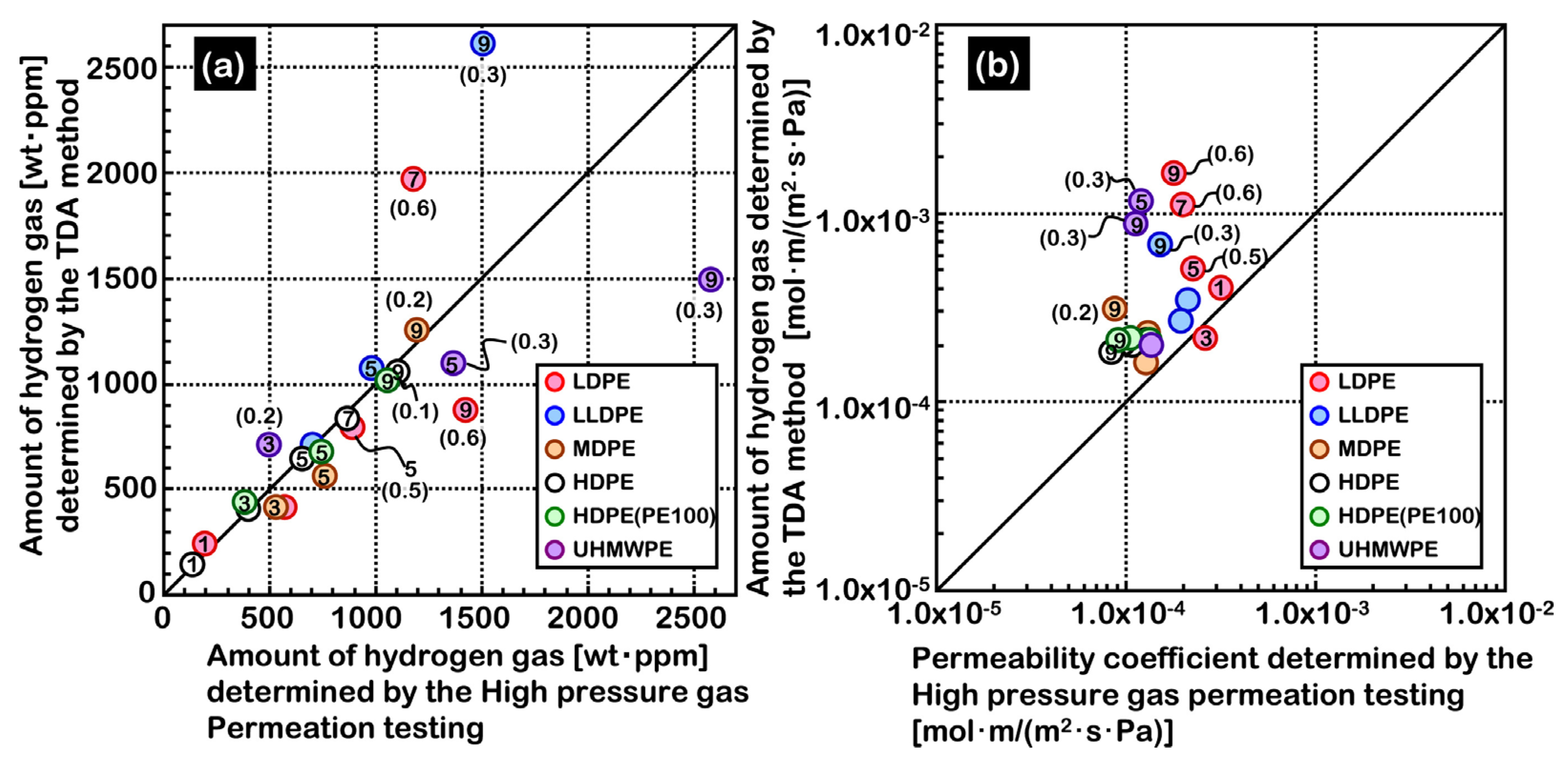
2.2.3. TDA Method versus HPHP Method
3. Factors Affecting Hydrogen Permeability
3.1. External Conditions
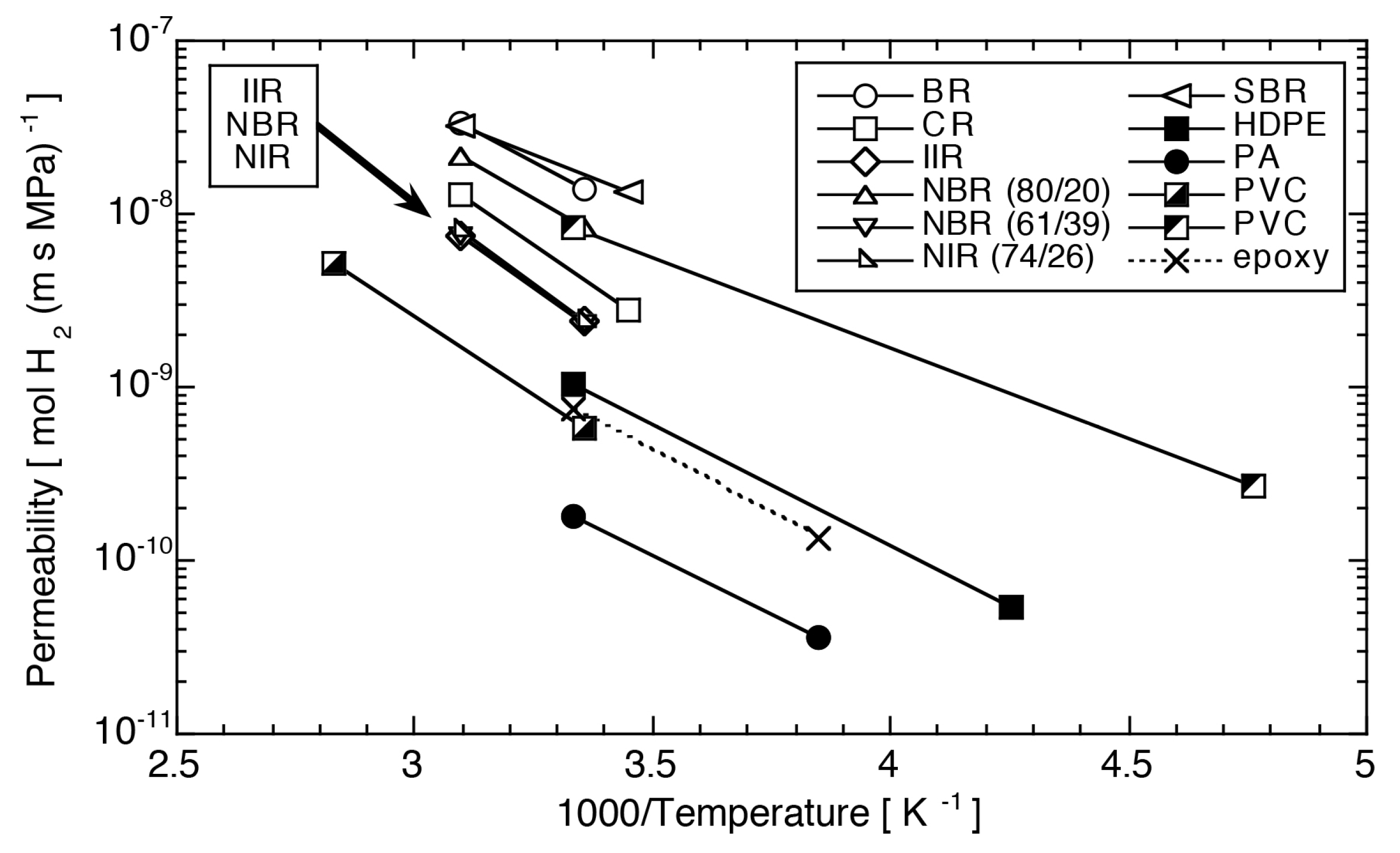
3.1.1. Temperature
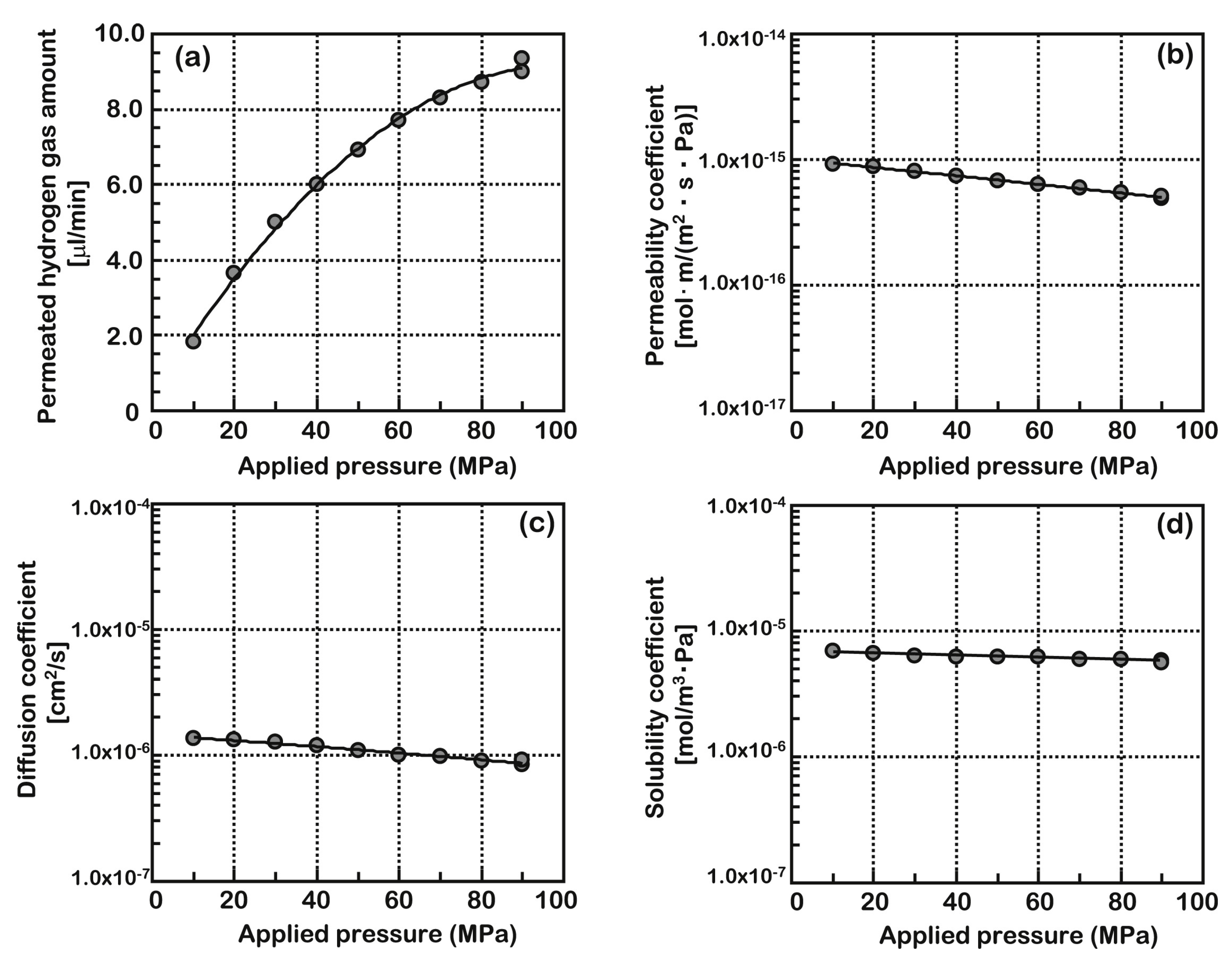
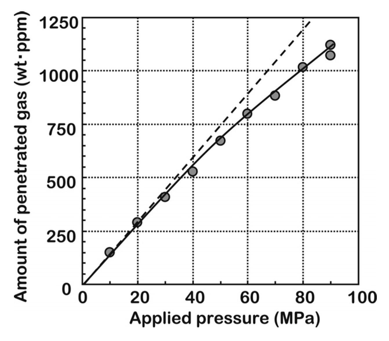
3.1.2. Pressure
3.2. Material Properties
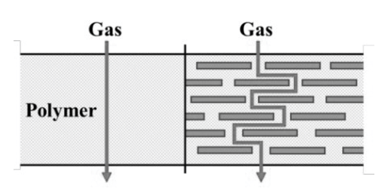
3.2.1. Crystallinity and Molecular Chain
3.2.2. Additives
3.3. Interaction between Gas and Material
4. Prediction Models
4.1. Dual-Mode Sorption Model
4.2. Gas–Polymer Matrix Model
4.3. Nonequilibrium Lattice Fluid Thermodynamic Model
4.4. Free Volume Theory
5. Conclusions
- Although the factors and rules of most gas permeation in polymers have been summarized, these rules are rarely concluded based on the hydrogen permeation in the liner materials (such as HDPE and polyamide, etc.) of the on-board type IV hydrogen storage tank. Therefore, this can only be regarded as a universal law and there is still a lack of systematic research on hydrogen permeation in the material of the on-board type IV hydrogen storage tank.
- The pressure in the type IV hydrogen storage tank is as high as 700 bar. Most of the experiments were carried out at low pressure and the hydrogen permeation data under high pressure is insufficient. In addition, there is no special experimental study on the plasticization of the liner material of the hydrogen storage tank in the high-pressure hydrogen environment, and no detailed evaluation of its physical and mechanical properties in a high-pressure hydrogen environment.
- Based on the high-pressure hydrogen permeation data, the prediction model needs to be further optimized and improved to ensure its accuracy and predictive ability in the description of permeation phenomena in a high-pressure environment.
- When polyamide is used as the liner material of the type IV hydrogen storage tank, the amine group and carbonyl group contained in the molecular chain will make the material have water absorption. The degree of water absorption of the material will lead to changes in many properties, so the influence of humidity on polyamide materials cannot be ignored.
Author Contributions
Funding
Conflicts of Interest
References
- ReferencesAl-Juboori, O.; Sher, F.; Hazafa, A.; Khan, M.K.; Chen, G.Z. The effect of variable operating parameters for hydrocarbon fuel formation from CO2 by molten salts electrolysis. J. CO2 Util. 2020, 40, 101193. [Google Scholar] [CrossRef]
- Al-Shara, N.K.; Sher, F.; Iqbal, S.Z.; Curnick, O.; Chen, G.Z. Design and optimization of electrochemical cell potential for hydrogen gas production. J. Energy Chem. 2021, 52, 421–427. [Google Scholar] [CrossRef]
- Al-Shara, N.K.; Sher, F.; Iqbal, S.Z.; Sajid, Z.; Chen, G.Z. Electrochemical study of different membrane materials for the fabrication of stable, reproducible and reusable reference electrode. J. Energy Chem. 2020, 49, 33–41. [Google Scholar] [CrossRef]
- Sher, F.; Al-Shara, N.K.; Iqbal, S.Z.; Jahan, Z.; Chen, G.Z. Enhancing hydrogen production from steam electrolysis in molten hydroxides via selection of non-precious metal electrodes. Int. J. Hydrog. Energy 2020, 45, 28260–28271. [Google Scholar] [CrossRef]
- Al-Shara, N.K.; Sher, F.; Yaqoob, A.; Chen, G.Z. Electrochemical investigation of novel reference electrode Ni/Ni(OH)(2) in comparison with silver and platinum inert quasi-reference electrodes for electrolysis in eutectic molten hydroxide. Int. J. Hydrog. Energy 2019, 44, 27224–27236. [Google Scholar] [CrossRef]
- Rivard, E.; Trudeau, M.; Zaghib, K. Hydrogen Storage for Mobility: A Review. Materials 2019, 12, 1973. [Google Scholar] [CrossRef] [Green Version]
- Balasooriya, W.; Clute, C.; Schrittesser, B.; Pinter, G. A Review on Applicability, Limitations, and Improvements of Polymeric Materials in High-Pressure Hydrogen Gas Atmospheres. Polym. Rev. 2021, 61, 1–36. [Google Scholar] [CrossRef]
- Mori, D.; Hirose, K. Recent challenges of hydrogen storage technologies for fuel cell vehicles. Int. J. Hydrog. Energy 2009, 34, 4569–4574. [Google Scholar] [CrossRef]
- Barthelemy, H.; Weber, M.; Barbier, F. Hydrogen storage: Recent improvements and industrial perspectives. Int. J. Hydrog. Energy 2017, 42, 7254–7262. [Google Scholar] [CrossRef]
- Pepin, J.; Laine, E.; Grandidier, J.C.; Benoit, G.; Mellier, D.; Weber, M.; Langlois, C. Replication of liner collapse phenomenon observed in hyperbaric type IV hydrogen storage vessel by explosive decompression experiments. Int. J. Hydrog. Energy 2018, 43, 4671–4680. [Google Scholar] [CrossRef]
- Ahluwalia, R.K.; Hua, T.Q.; Peng, J.K. On-board and Off-board performance of hydrogen storage options for light-duty vehicles. Int. J. Hydrog. Energy 2012, 37, 2891–2910. [Google Scholar] [CrossRef]
- Fujiwara, H.; Ono, H.; Ohyama, K.; Kasai, M.; Kaneko, F.; Nishimura, S. Hydrogen permeation under high pressure conditions and the destruction of exposed polyethylene-property of polymeric materials for high-pressure hydrogen devices (2)-. Int. J. Hydrog. Energy 2021, 46, 11832–11848. [Google Scholar] [CrossRef]
- Klopffer, M.H.; Flaconneche, B. Transport properties of gases in polymers: Bibliographic review. Oil Gas Sci. Technol. 2001, 56, 223–244. [Google Scholar] [CrossRef]
- Yamabe, J.; Nishimura, S. Influence of fillers on hydrogen penetration properties and blister fracture of rubber composites for O-ring exposed to high-pressure hydrogen gas. Int. J. Hydrog. Energy 2009, 34, 1977–1989. [Google Scholar] [CrossRef]
- Fujiwara, H.; Ono, H.; Onoue, K.; Nishimura, S. High-pressure gaseous hydrogen permeation test method -property of polymeric materials for high-pressure hydrogen devices (1)-. Int. J. Hydrog. Energy 2020, 45, 29082–29094. [Google Scholar] [CrossRef]
- Brubaker, D.W.; Kammermeyer, K. Flow of gases through plastic membranes. Ind. Eng. Chem. 1953, 45, 1148–1152. [Google Scholar] [CrossRef]
- Van Amerongen, G.J. The permeability of different rubbers to gases and its relation to diffusivity and solubility. J. Appl. Phys. 1946, 17, 972–985. [Google Scholar] [CrossRef]
- Lorge, O.; Briscoe, B.; Dang, P. Gas induced damage in poly (vinylidene fluoride) exposed to decompression. Polymer 1999, 40, 2981–2991. [Google Scholar] [CrossRef]
- Stevenson, A.; Morgan, G. Fracture of elastomers by gas decompression. Rubber Chem. Techol. 1995, 68, 197–211. [Google Scholar] [CrossRef]
- George, S.C.; Thomas, S. Transport phenomena through polymeric systems. Prog. Polym. Sci. 2001, 26, 985–1017. [Google Scholar] [CrossRef]
- Barth, R.R.; Simmons, K.L.; San Marchi, C. Polymers for Hydrogen Infrastructure and Vehicle Fuel Systems: Applications, Properties, and Gap Analysis; Sandia National Laboratories: Albuquerque, NM, USA; Livermore, CA, USA, 2013. [CrossRef] [Green Version]
- Klopffer, M.H.; Berne, P.; Espuche, E. Development of Innovating Materials for Distributing Mixtures of Hydrogen and Natural Gas. Study of the Barrier Properties and Durability of Polymer Pipes. Oil Gas Sci. Technol. 2015, 70, 305–315. [Google Scholar] [CrossRef] [Green Version]
- Takeuchi, K.; Kuo, A.T.; Hirai, T.; Miyajima, T.; Urata, S.; Terazono, S.; Okazaki, S.; Shinode, W. Hydrogen Permeation in Hydrated Perfluorosulfonic Acid Polymer Membranes: Effect of Polymer Crystallinity and Equivalent Weight. J. Phys. Chem. C 2019, 123, 20628–20638. [Google Scholar] [CrossRef]
- Kane, M. Permeability, Solubility, and Interaction of Hydrogen in Polymers—An Assessment of Materials for Hydrogen Transport; SRS: Aiken, SC, USA, 2008. [Google Scholar] [CrossRef] [Green Version]
- Cui, Y.B.; Kundalwal, S.I.; Kumar, S. Gas barrier performance of graphene/polymer nanocomposites. Carbon 2016, 98, 313–333. [Google Scholar] [CrossRef] [Green Version]
- Habel, C.; Tsurko, E.S.; Timmins, R.L.; Hutschreuther, J.; Kunz, R.; Schuchardt, D.D.; Rosenfeldt, S.; Altstadt, V.; Breu, J. Lightweight Ultra-High-Barrier Liners for Helium and Hydrogen. ACS Nano 2020, 14, 7018–7024. [Google Scholar] [CrossRef] [PubMed]
- Castagnet, S.; Grandidier, J.C.; Comyn, M.; Benoit, G. Mechanical Testing of Polymers in Pressurized Hydrogen: Tension, Creep and Ductile Fracture. Exp. Mech. 2012, 52, 229–239. [Google Scholar] [CrossRef]
- Klopffer, M.-H.; Berne, P.; Castagnet, S.; Weber, M.; Hochstetter, G.; Espuche, E. Polymer pipes for Distributing Mixtures of Hydrogen and Natural Gas. Evolution of Their Transport and Mechanical Properties after an Ageing under an Hydrogen Environment. In Proceedings of the World hydrogen energy conference: Building bridges to the hydrogen energy economy, Essen, Germany, 16–21 May 2010. [Google Scholar]
- Maus, S.; Hapke, J.; Ranong, C.N.; Wuchner, E.; Friedlmeier, G.; Wenger, D. Filling procedure for vehicles with compressed hydrogen tanks. Int. J. Hydrog. Energy 2008, 33, 4612–4621. [Google Scholar] [CrossRef]
- Rogers, C. Permeation of gases and vapours in polymers. In Polymer Permeability; Springer: Dordrecht, Holland, 1985; pp. 11–73. [Google Scholar]
- Baker, R.W. Polymer Permeability; Comyn, J., Ed.; Elsevier Applied Science Publishers: London, UK, 1985; p. 383. ISBN 0-85334-322-5. [Google Scholar]
- Klopffer, M.H.; Flaconneche, B.; Odru, P. Transport properties of gas mixtures through polyethylene. Plast. Rubber Compos. 2007, 36, 184–189. [Google Scholar] [CrossRef]
- Naito, Y.; Mizoguchi, K.; Terada, K.; Kamiya, Y. The Effect of Pressure on Gas Permeation through Semicrystalline Polymers above the Glass-Transition Temperature. J. Polym. Sci. Pol. Phys. 1991, 29, 457–462. [Google Scholar] [CrossRef]
- Li, N.; Long, R. Permeation through plastic films. AIChE J. 1969, 15, 73–80. [Google Scholar] [CrossRef]
- Fumitoshi, K.K.O.; Hirotada, F.; Shin, N. Influence of high-pressure hydrogen gas on crystalline polymers. In Proceedings of the 33rd Polymer Degradation Discussion Group, St Julians, Malta, 1–5 September 2019. [Google Scholar]
- Humpenöder, J. Gas permeation of fibre reinforced plastics. Cryogenics 1998, 38, 143–147. [Google Scholar] [CrossRef]
- Yersak, T.A.; Baker, D.R.; Yanagisawa, Y.; Slavik, S.; Immel, R.; Mack-Gardner, A.; Herrmann, M.; Cai, M. Predictive model for depressurization-induced blistering of type IV tank liners for hydrogen storage. Int. J. Hydrog. Energy 2017, 42, 28910–28917. [Google Scholar] [CrossRef]
- Park, G.S.; Crank, J. Diffusion in Polymers; Academic Press: London, UK; New York, NY, USA, 1968. [Google Scholar]
- Pepin, J.; Laine, E.; Grandidier, J.C.; Castagnet, S.; Blanc-vannet, P.; Papin, P.; Weber, M. Determination of key parameters responsible for polymeric liner collapse in hyperbaric type IV hydrogen storage vessels. Int. J. Hydrog. Energy 2018, 43, 16386–16399. [Google Scholar] [CrossRef]
- Smith, B.; Anovitz, L.M. IV.F.1 Lifecycle Verification of Polymeric Storage Liners. Available online: https://www.hydrogen.energy.gov/pdfs/progress13/iv_f_1_smith_2013.pdf (accessed on 14 July 2021).
- Flaconneche, B.; Martin, J.; Klopffer, M.H. Permeability, Diffusion and Solubility of Gases in Polyethylene, Polyamide 11 and Poly (Vinylidene Fluoride). Oil Gas Sci. Technol. 2006, 56, 261–278. [Google Scholar] [CrossRef] [Green Version]
- Klopffer, M.H.; Berne, P.; Weber, M.; Castagnet, S.; Hochstetter, G.; Espuche, E. New materials for hydrogen distribution networks: Materials development & technico-economic benchmark. Diffus. Mater. Dimat 2011 2012, 323, 407–412. [Google Scholar] [CrossRef]
- Kunz, D.A.; Schmid, J.; Feicht, P.; Erath, J.; Fery, A.; Breu, J. Clay-Based Nanocomposite Coating for Flexible Optoelectronics Applying Commercial Polymers. ACS Nano 2013, 7, 4275–4280. [Google Scholar] [CrossRef] [PubMed]
- DeRocher, J.P.; Gettelfinger, B.T.; Wang, J.S.; Nuxoll, E.E.; Cussler, E.L. Barrier membranes with different sizes of aligned flakes. J. Membr. Sci. 2005, 254, 21–30. [Google Scholar] [CrossRef]
- Sun, Y.; Lv, H.; Zhou, W.; Zhang, C. Research on hydrogen permeability of polyamide 6 as the liner material for type ΙV hydrogen storage tank. Int. J. Hydrog. Energy 2020, 45, 24980–24990. [Google Scholar] [CrossRef]
- Ebina, T.; Ishii, R.; Aizawa, T.; Yoshida, H. Development of Clay-based Film and Its Application to Gas Barrier Layers of Composite Tanks. J. Jpn. Pet. Inst. 2017, 60, 121–126. [Google Scholar] [CrossRef] [Green Version]
- Picard, E.; Gérard, J.F.; Espuche, E. Reinforcement of the Gas Barrier Properties of Polyethylene and Polyamide Through the Nanocomposite Approach: Key Factors and Limitations. Oil Gas Sci. Technol. Rev. d’IFP Energ. Nouv. 2013, 70, 237–249. [Google Scholar] [CrossRef] [Green Version]
- Ismail, A.F.; Lorna, W. Penetrant-induced plasticization phenomenon in glassy polymers for gas separation membrane. Sep. Purif. Technol. 2002, 27, 173–194. [Google Scholar] [CrossRef]
- Minelli, M.; Oradei, S.; Fiorini, M.; Sarti, G.C. CO2 plasticization effect on glassy polymeric membranes. Polymer 2019, 163, 29–35. [Google Scholar] [CrossRef]
- Barrer, R.; Barrie, J.; Slater, J. Sorption and diffusion in ethyl cellulose. Part III. Comparison between ethyl cellulose and rubber. J. Polym. Sci. 1958, 27, 177–197. [Google Scholar] [CrossRef]
- Fleming, G.K.; Koros, W.J. Dilation of polymers by sorption of carbon dioxide at elevated pressures. 1. Silicone rubber and unconditioned polycarbonate. Macromolecules 1986, 19, 2285–2291. [Google Scholar] [CrossRef]
- Jordan, S.S.; Koros, W.J. A free volume distribution model of gas sorption and dilation in glassy polymers. Macromolecules 1995, 28, 2228–2235. [Google Scholar] [CrossRef]
- Koros, W.J.; Paul, D.R.; Rocha, A.A. Carbon dioxide sorption and transport in polycarbonate. J. Polym. Sci. Polym. Phys. Ed. 1976, 14, 687–702. [Google Scholar] [CrossRef]
- Paul, D.R.; Koros, W.J. Effect of partially immobilizing sorption on permeability and the diffusion time lag. J. Polym. Sci. Polym. Phys. Ed. 1976, 14, 675–685. [Google Scholar] [CrossRef]
- Aminabhavi, T.M.; Aithal, U.S.; Shukla, S.S. An overview of the theoretical models used to predict transport of small molecules through polymer membranes. Polym. Rev. 1988, 28, 421–474. [Google Scholar] [CrossRef]
- Bondar, V.I.; Kamiya, Y.; Yampol’Skii, Y.P. On pressure dependence of the parameters of the dual-mode sorption model. J. Polym. Sci. Part B Polym. Phys. 1996, 34, 369–378. [Google Scholar] [CrossRef]
- Pace, R.; Datyner, A. Statistical mechanical model of diffusion of complex penetrants in polymers. II. Applications. J. Polym. Sci. Polym. Phys. Ed. 1979, 17, 1693–1708. [Google Scholar] [CrossRef]
- Raucher, D.; Sefcik, M.D. Gas transport and cooperative main-chain motions in glassy polymers. Ind. Gas Sep. 1983, 89–110. [Google Scholar]
- Raucher, D.; Sefcik, M.D. Sorption and Transport in Glassy Polymers: Gas—Polymer—Matrix Model; American Chemical Society: Washington, DC, USA, 1983. [Google Scholar]
- Minelli, M.; Campagnoli, S.; De Angelis, M.G.; Doghieri, F.; Sarti, G.C. Predictive Model for the Solubility of Fluid Mixtures in Glassy Polymers. Macromolecules 2011, 44, 4852–4862. [Google Scholar] [CrossRef]
- Galizia, M.; De Angelis, M.G.; Sarti, G.C. Sorption of hydrocarbons and alcohols in addition-type poly (trimethyl silyl norbornene) and other high free volume glassy polymers. II: NELF model predictions. J. Membr. Sci. 2012, 405, 201–211. [Google Scholar] [CrossRef]
- Minelli, M.; Sarti, G.C. Permeability and diffusivity of CO2 in glassy polymers with and without plasticization. J. Membr. Sci. 2013, 435, 176–185. [Google Scholar] [CrossRef]
- Sanchez, I.C.; Lacombe, R.H. Statistical Thermodynamics of Polymer-Solutions. Macromolecules 1978, 11, 1145–1156. [Google Scholar] [CrossRef] [Green Version]
- Minelli, M.; Sarti, G.C. Gas permeability in glassy polymers: A thermodynamic approach. Fluid Phase Equilibria 2016, 424, 44–51. [Google Scholar] [CrossRef]
- Minelli, M.; Sarti, G.C. Thermodynamic model for the permeability of light gases in glassy polymers. AIChE J. 2015, 61, 2776–2788. [Google Scholar] [CrossRef]
- Rodgers, P.A. Pressure Volume Temperature Relationships for Polymeric Liquids—A Review of Equations of State and Their Characteristic Parameters for 56 Polymers. J. Appl. Polym. Sci. 1993, 48, 1061–1080. [Google Scholar] [CrossRef]
- Minelli, M.; Sarti, G.C. Elementary prediction of gas permeability in glassy polymers. J. Membr. Sci. 2017, 521, 73–83. [Google Scholar] [CrossRef]
- Bondi, A.V. van der Waals volumes and radii. J. Phys. Chem. 1964, 68, 441–451. [Google Scholar] [CrossRef]
- Fujita, H.; Kishimoto, A.; Matsumoto, K. Concentration and temperature dependence of diffusion coefficients for systems polymethyl acrylate and n-alkyl acetates. Trans. Faraday Soc. 1960, 56, 424–437. [Google Scholar] [CrossRef]
- Doolittle, A.K. Studies in Newtonian flow. II. The dependence of the viscosity of liquids on free-space. J. Appl. Phys. 1951, 22, 1471–1475. [Google Scholar] [CrossRef]
- Doolittle, A.K. Studies in Newtonian flow. III. The dependence of the viscosity of liquids on molecular weight and free space (in homologous series). J. Appl. Phys. 1952, 23, 236–239. [Google Scholar] [CrossRef]
- Peterlin, A. Dependence of diffusive transport on morphology of crystalline polymers. J. Macromol. Sci. Part B Phys. 1975, 11, 57–87. [Google Scholar] [CrossRef]


| Molding Methods | Polymer | Experimental Conditions | Comparison of Results (P) | |
|---|---|---|---|---|
| Temperature Range (°C) | Pressure (Bar) | |||
| Injection-molded | HDPE | −30~85 | about 135 | P (Injection-molded HDPE)> P (Extrusion-molded HDPE)≈ P (Extrusion-molded PA6)> P (Compression-molded TLCP Blow-molded PET |
| Extrusion-molded | HDPE | |||
| Extrusion-molded | PA6 | |||
| Compression-molded | TLCP | |||
| Blow-molded | PET | |||
Publisher’s Note: MDPI stays neutral with regard to jurisdictional claims in published maps and institutional affiliations. |
© 2021 by the authors. Licensee MDPI, Basel, Switzerland. This article is an open access article distributed under the terms and conditions of the Creative Commons Attribution (CC BY) license (https://creativecommons.org/licenses/by/4.0/).
Share and Cite
Su, Y.; Lv, H.; Zhou, W.; Zhang, C. Review of the Hydrogen Permeability of the Liner Material of Type IV On-Board Hydrogen Storage Tank. World Electr. Veh. J. 2021, 12, 130. https://doi.org/10.3390/wevj12030130
Su Y, Lv H, Zhou W, Zhang C. Review of the Hydrogen Permeability of the Liner Material of Type IV On-Board Hydrogen Storage Tank. World Electric Vehicle Journal. 2021; 12(3):130. https://doi.org/10.3390/wevj12030130
Chicago/Turabian StyleSu, Ying, Hong Lv, Wei Zhou, and Cunman Zhang. 2021. "Review of the Hydrogen Permeability of the Liner Material of Type IV On-Board Hydrogen Storage Tank" World Electric Vehicle Journal 12, no. 3: 130. https://doi.org/10.3390/wevj12030130
APA StyleSu, Y., Lv, H., Zhou, W., & Zhang, C. (2021). Review of the Hydrogen Permeability of the Liner Material of Type IV On-Board Hydrogen Storage Tank. World Electric Vehicle Journal, 12(3), 130. https://doi.org/10.3390/wevj12030130