1. Introduction
Design, performance, and efficiency are core features for marketing a vehicle [
1]. By considering characteristics such as generated pollution and fossil gas emissions, electric vehicles constitute clean alternatives in contrast to conventional ones [
2,
3]. Among them, electric bicycles stand out as a less polluting, compact, and lightweight option, with great utility for mobility in large cities worldwide [
4]. However, short ranges derived from the battery’s energy storage limitations bound their massification [
5,
6]. For this reason, the performance modeling, the study of the components’ efficiency, and its integration play a fundamental role in improving range [
7,
8].
The basic e-bike configuration is presented by Muetze et al. [
9], consisting of a controller that manages the energy flow from the battery to the electric motor, this energy works parallel to the energy produced by the cyclist. Different e-bike classification criteria are also presented in the article, namely: motor type, motor assembly, motor placement, assist type, throttle type, and battery type.
Performance is one of the most studied topics in electric bicycles. Muetze et al. [
9] stated the dynamic equations of an electric bicycle and then performed physical tests with an electric bicycle equipped with sensors. As a result, they described the operation of the system presenting the maximum power, speed, and instantaneous power against variations of weight, slope, and wind speed. Evtimov et al. [
10] performed experimental tests in different city routes with an electric bicycle equipped with sensors, enabling them to characterize aspects such as power, energy consumed, maximum current, maximum speed, regenerated Ah, and range. Kheirandish et al. [
1] presented a PEM (polymer electrolyte membrane) fuel cell-powered electric bicycle equipped with different sensors and implemented an experimental evaluation. The results show the behavior of variables such as system voltage, current, efficiency, and cell power. Kang et al. [
11] proposed an assessment method for the engine and battery behavior of an electric vehicle using a dynamometer.
The dynamic features and power required by an electric bicycle have been studied under the effect of parameters such as rider mass, bicycle mass, air speed, crank length, wheel radius, and slope. Dynamic equations that govern an electric bicycle are used for this purpose, speed, distance traveled, and power behavior are simulated, and experimental tests are conducted to validate mathematical models [
12,
13,
14]. Hung et al. [
12] focus their study on a hub motor bicycle with a fixed gear ratio for the chain. Hung et al. [
13] study a hub motor electric bicycle and a semi-automatic transmission, analyzing and presenting results for each possible transmission ratio. In the study, they establish a motor efficiency of 70%. Hung et al. [
14] study a hub motor electric bicycle considering a variable transmission ratio for the sprocket and dynamic models for the battery.
Arango et al. [
15] compare the performance of hub and mid-drive motors on electric bicycles for mountain routes. They experimentally characterize the two types of motors on a test bench, obtaining their torque, RPM, and efficiency curves for each assist level. Subsequently, they use this information and the system’s dynamic equations to simulate bicycles’ performance on mountain routes. For the e-bike’s case, it was concluded that the motor placement is the most relevant factor for the system’s energy consumption, and it was shown that, for steep roads, middle drive motors use about 18% less energy than hub motors.
Electric bicycles range and its optimization are still underdeveloped. Gebhard et al. [
16] worked on improving the prediction of electric bicycle range by assessing two prediction methods considering the cyclist behavior as well as the route. Ferreira et al. [
5] present a mobile application aimed to provide useful information to the cyclist, such as range prediction based on a specified route, cyclist effort management, battery charging process management, among others. De La Iglesia et al. [
17] developed an intelligent engine management system to optimize the selection of assistance, intended for reducing battery power consumption. This is achieved by computing information provided by sensors on the bicycle, historical data from other cyclists, and neural networks. Its results achieved a decrease in electricity consumption along the route, saving 10.32% of consumption by controlling the electric bicycle assist level.
As showcased, multiple studies on e-bikes have mainly analyzed the external forces affecting the system (weight, rolling, and drag); however, the behavior of internal energy losses in these systems due to their components has not been analyzed yet. At the same time, no studies have been presented that optimize the operational range of the bicycle based on the knowledge of its performance, nor its components’ behavior. Minav et al. [
18] and Wu et al. [
19] quantified the efficiency of machine components such as forklifts or electric cars using maps, curves, and punctual values. This information was used to determine the efficiency of such systems. Moreover, it was possible to analyze energy losses and enhancement opportunities in the systems. In addition, knowledge on energy accumulators and powertrain elements efficiency in electric vehicles enabled the implementation of energy-efficient driving strategies [
20]. Based on this, the article presents an experimental analysis of internal energy losses for a mid-drive motor electric bicycle by characterizing its components and the system through maps, curves, and values. The integration of such information and the system’s performance analysis results in the presentation of a novelty management strategy aimed at improving the electric bicycle’s range by controlling the transmission ratio and assistance level.
The remaining contents of the article are ordered as follows:
Section 2 presents the materials and methods used to develop and assess the proposed driving strategy;
Section 3 shows the results obtained from experimental and computational studies;
Section 4 showcases the discussion.
2. Materials and Methods
This section initially presents the method by which the energy flow through the bicycle is analyzed, as well as the losses in its components; then, the equations for the system’s dynamic behavior and performance are presented; after that, the proposed driving strategy to increase the e-bike’s range is described; and finally, a case study is showcased in which the performance of the driving strategy is compared with other driving techniques.
2.1. E-Bike Losses Characterization
To identify the energy flows through an e-bike, its transformations, and losses, different studies present their block diagram model [
9,
15].
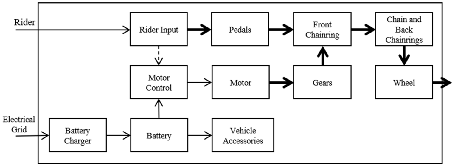
Figure 1 shows the block diagram for a mid-drive motor e-bike. It presents the energy and information flows for the system regarding the energy delivered by the cyclist and the information transmitted by the cyclist.
For this study, a commonly used e-bike and its components were subject to different experiments to characterize efficiency.
Table 1 presents specifications analyzed for this e-bike.
The e-bike was analyzed by subsystems, namely: the charger; the battery; the controller, motor, and reduction gears (CMRGs); and the chain drive. The CMRGs group was a subsystem analyzed together because their physical construction did not allow partitioning without partially or entirely affecting functionality.
2.1.1. Charger
This element draws electricity from the power grid and rectifies it to supply the battery using an AC-DC converter followed by a DC-DC converter. The charging process comprises two stages: Constant current (CC) charge and constant voltage (CV) charge. Charger losses are mainly due to conduction losses, MOSFET (metal–oxide–semiconductor field-effect transistor) and diode switching, and core losses [
21,
22].
The efficiency of the charger was characterized through an experimental test in which a full battery charge cycle (from 0% to 100% state of charge (SoC)) was performed. During this process, current and voltage sensors were connected to the charger input and output (power cables and battery connector). A microcontroller board stored the sensors’ measurements every minute, with each measurement corresponding to the average of 100 sensor readings. The efficiency of the charger (
) is calculated as the input energy
(taken from the power grid) and the output energy
(delivered to the battery) ratio, as shown in Equation (1). Voltage
, current
, and time
measurements, and power
and electrical energy
equations were used to calculate such energy measurements, this is represented with Equations (2) and (3).
2.1.2. Battery
Battery efficiency is defined as the ampere-hours removed from the battery to the ampere-hours restored to the battery ratio, for the same final and initial conditions (SoC and temperature) [
23]. Factors such as parasitic reactions in its electrochemistry, battery aging, ultra-fast charges, and high working loads affect the energy delivering capacity of the battery [
24]. E-bikes use different battery types such as lead, nickel-cadmium, NiMH, lithium-ion polymer, or lithium-ion, the latter ones being the most widely used [
25]. Farhad et al. [
26] generated efficiency maps for different lithium-ion battery families, using their results, and after determining the energy density of a battery, it is possible to establish the operating efficiency relying on the C ratio alone.
The battery’s energy performance was characterized through an experimental test aimed to generate a function representing the battery efficiency as a function of the discharge current. For this purpose, the energy delivered by the battery operating at different C ratios was quantified and compared with the energy stored in the battery during the charging stage. This experiment was divided into two processes: charging and discharging. For the charging process, the electrical energy entering the battery was quantified using the calculations and methods developed for the characterization of the charger efficiency. For the discharge process, the electrical energy delivered by the battery was quantified by implementing a circuit in which the battery was connected to a variable resistive load and complementing the circuit with voltage and current sensors. The discharge rates of the tests are presented in
Table 2.
Equations (2) and (3) allowed the calculation of the charge
and discharge
energy of the battery, so its efficiency at each operating point was calculated as presented in Equation (4), where
is the battery efficiency.
2.1.3. Controller, Motor, and Reduction Gears (CMRGs)
These elements are closely linked, and their selection depends mainly on the motor. Despite the variety of existing electric motors, e-bikes are generally equipped with DC motors, with or without brushes. Brushless DC motors (BLDCs) are more advantageous for electric bicycles than brushed DC motors, because they are more efficient and smaller, yet their control is more complex [
9].
Hung et al. [
25] referenced various types of controls for BLDC motors on e-bikes such as PID control, fuzzy logic control, torque control, traditional power assistance approach, and sensorless power assist control method. Regardless of the control method, the controller has always an embedded inverter, which generally uses 6 MOSFET transistors to convert electricity from DC to AC. This process involves energy heat losses due to the internal resistance of MOSFET transistors and the switching process [
27,
28].
Motor efficiency is represented through efficiency maps as a function of its torque and RPM [
29]. This component can be coupled to gearboxes or directly driven; however, reduction gears are commonly used to decrease the motor rotation speeds respecting the bicycle wheels, thereby generating a more efficient operation. Spur gears are common in mid-drives and hub-drives [
30,
31]. The efficiency of spur gears is over 98.0% without any noticeable variation as the load or speed changes [
32,
33].
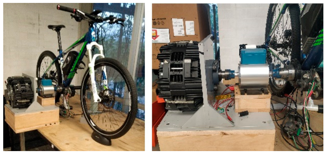
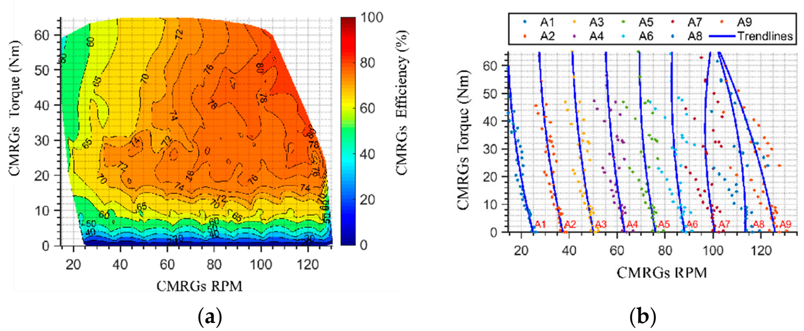
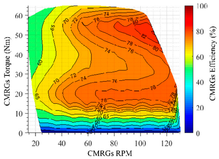
This subsystem was analyzed through an experiment aimed at developing the efficiency map of the CMRGs group. For this purpose, the electrical power drawn by the controller from the battery was compared with the mechanical power delivered by the gear motor at the output shaft. To conduct the experiment, a voltmeter and an amperemeter were connected to the controller input. A torque meter was also coupled directly to the gear motor output shaft, and this to a disc brake. The mechanical assembly of the experiment is shown in
Figure 2.
The experiment went through the entire map of torque vs. RPM possibilities by varying the braking torque, with values from 0 to 70 Nm, and varying the motor speed through the nine assist levels that the controller possesses. During the tests, the electrical power
was calculated using voltage and current measurements, while mechanical power
was calculated with data provided by the torque meter (torque and RPM). With this, the efficiency of the CMGRs group
was quantified for each operation point using Equation (5).
where
is the torque on the CMRGs output shaft and
is the output shaft angular speed. To facilitate the use of the information provided by the CMRGs efficiency map, data obtained in the experiment was subject to a linear regression process which sought to represent it through parametric equations as a function of the output torque and RPM.
2.1.4. Chain Drive
The derailleur system is the most used chain drive configuration for bicycles, presenting efficiencies ranging between 80% and 98%. Chain drive efficiency was represented by different functions reported by Spicer [
34]. His results demonstrated that the efficiency of a chain drive varies respecting the reciprocal of the tension to which it is exposed, where the greater the tension the greater the efficiency. Factors such as RPM, power, torque, chainrings teeth count, and chain misalignment have minor incidences over the performance of the mechanism. This information was used to simulate the chain drive efficiency for different transmission ratios in this study case [
34,
35,
36].
2.1.5. Global System Efficiency
The e-bike system’s global efficiency
is presented as a map, and it is calculated based on the integration of the efficiency of each subsystem, namely: charger, battery, CMGRs, and chain drive. The efficiency of the system at each operating point was mathematically represented as:
2.2. Bicycle Dynamics
The mathematical model used to evaluate the dynamics, and the analyzed system simulation are described below. First, the external forces and the equation governing the motion of the system are presented; then the equations characterizing its velocity and displacement are presented; and finally, the equations representing the performance of its components and their energy consumption are presented.
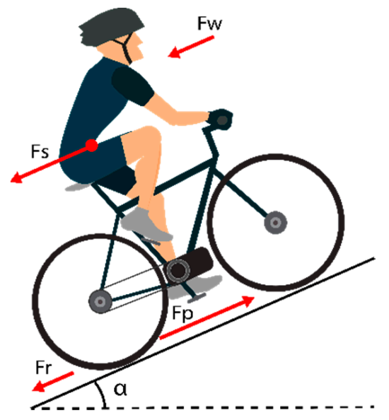
The dynamic diagram presenting the forces that govern the movement of an electric bicycle is shown in
Figure 3, and the equation which represents this behavior is described as:
Where is the propulsion force, is the rolling resistance force, is the force generated by gravity, is the aerodynamic drag force, is the system mass, is the distance, is the time, is the gravitational acceleration, is the rolling coefficient, is the road slope angle, is the drag coefficient, is the air density, is the system frontal area, and is the relative speed of the system respecting the air.
By knowing the terms in Equation (7), and integrating them, the system speed
is obtained through algebraic differences as:
Where
is the speed differential and
is the previous system speed. The integration of the system speed for a delta time allows the calculation of the distance traveled during that instant
, and this enables the calculation of the accumulated distance.
Once the equations governing the dynamics of the system, its velocity, and displacement have been presented, the relationships representing the performance of its components and their energy consumption are presented.
The torque received by the wheel
is calculated with the propulsive force and the wheel radius
as:
Knowing the torque received by the wheel allows the chain tension
and its efficiency
to be determined by using the functions presented by Spicer [
34], the radius of the sprocket in the cassette
and the following relationships:
The efficiency of the chain, its transmission ratio
, and the torque received by the wheel are used to determine the torque on the crank spindle
, calculated as:
The torque on the crank spindle is the sum of the torque delivered by the cyclist
and the torque delivered by the controller, motor, reduction gears (CMRGs) group
:
The torque delivered by the cyclist is presented as a relationship between its cadence
and its capacity to deliver power
, expressed as:
The RPM on the wheel
are dependent on the system speed and the wheel radius, and are calculated as:
The RPM on the crank spindle
are dependent on the chain transmission ratio and the wheel RPM, so they are calculated as:
Using the CMRGs efficiency map, the RPM at the crank spindle, and the torque at the CMRGs, its efficiency
is determined as:
Through the relations presented in Equation (5), the mechanical power of the CMRGs is calculated employing its torque and RPM. The electrical power of the CMRGs is also determined by associating its mechanical power and its efficiency. In turn, the current received by the CMRGs is calculated using the electrical power of the CMRGs and the battery voltage .
The energy charged to the battery is calculated with the electrical energy delivered to the CMRGs and the efficiency of the battery. The same relationship applies for its power and current, so the current removed from the battery
is calculated as:
The voltage product integration and the current removed from the battery for a differential of time indicates the watt-hours consumed
, this is expressed as:
Furthermore, by relating the watt-hours consumed with the distance differential for the same time delta, it is possible to identify the ratio of watt-hours consumed per unit of distance.
2.3. Bicycle Performance
To fulfill the necessary relationships to evaluate the behavior of an electric bicycle, the performance equations are described below. The power developed both by the electric motor and the cyclist is used to overcome the power losses on the components
as well as that generated by the slope (
), rolling
and drag (
) [
15]. This relationship is expressed as:
where
is the sum of the power produced by the cyclist
and the power produced by the electric motor
. The power consumed to overcome slope, rolling, and drag is calculated as:
where
stands for each power,
is each force, and
is the relative speed to the ground. The power losses for each component are expressed as:
where
is the power that enters each component,
is the power delivered by the component, and
is the component efficiency.
2.4. Driving Strategy
A driving strategy is proposed to enhance the range of the system, modeled as an optimization problem intended to determine the operational point of the system where the best ratio of per unit of distance covered energy consumed is given. The strategy is based on indicating the assistance level and the chain transmission ratio depending on the slope to which the system is submitted. For this purpose, the performance, and dynamic equations (equations to which the problem is subject) are used. As domain restrictions, there are:
Bicycle speed between the desired speed ranges must be assured; the RPM on the crank spindle must be in range with the maximum and minimum angular speeds generated by the assistance levels (AL); the chain transmission ratio will only have values between the possible chain wheel–cassette combinations; the assistance levels are determined by the bicycle controller; the torque at the CMRGs cannot take values higher than its maximum capacity; and the torque delivered by the CMRGs must be greater or equal to the torque delivered by the cyclist, thus enabling the electrical system to execute most of the work.
2.4.1. Maximization Function
The electrical power and its transformation through the system is controlled by managing the chain transmission ratio and the assistance level (AL). The analysis of possible combinations for these two elements allows determining the possible operational points where the system reaches static equilibrium. Therefore, it is possible to identify the combination offering the best per unit of distance energy consumed ratio to maximize its range. Consequently, the function to be maximized is expressed as:
2.4.2. Chain Transmission Ratio and Assistance Level Selection Algorithm
The following algorithm is used to identify the optimum assistance level and chain transmission ratio:
Identify the slope.
Generate a row vector of possible system desired speeds
, for
:
:
(m/s).
Calculate a distance traveled row vector by integrating each position of vector by a differential of time.
Calculate an RPM on the wheel row vector by using Equation (19) at each position of the vector .
Generate an RPM on the crank spindle
array in which each row represents the
vector related to each gear ratio, through Equation (20).
Generate a propulsion force () row vector on the bicycle based on Equation (8), system parameters and considering a static equilibrium (no acceleration) system applied to each position of the vector .
Calculate a torque on the wheel () row vector with each position of the vector , Equation (13), and the wheel radius.
Generate a torque on the crank spindle (
) array, in which each row represents the vector
related to each chain transmission ratio and the chain efficiency by using Equations (14)–(16).
Calculate a cyclist torque array with each position of array , cyclist power, and Equation (18).
Calculate a torque delivered by CMRGs array by applying Equation (17) for each position of arrays and .
Calculate a mechanical power of the CMRGs group array by using Equation (5) for each position of arrays and .
Calculate an efficiency in the CMRGs group array by applying, for each position of arrays and , the function expressed in Equation (21).
Calculate a Watt-hours removed from the battery array using, for each position of arrays and , Equations (5), (22), and (23).
Calculate an energy consumption per unit of distance
array by dividing each row of array
by vector
.
Identify the minimum value in array and its position (i, j). The ideal chain transmission ratio in which the system should operate is identified with the (i) position. The ideal crank spindle RPM is identified by finding the (i, j) position in array . The ideal value is selected using this value and the curves representing each assistance level.
2.5. Study Case
Multiple simulations were performed when implementing the dynamics of the system to contrast the operation of the driving strategy proposed with other driving techniques. The simulations employed the characteristics of the electric bicycle described above. The remaining parameters of the system are presented in
Table 3. Cyclist power was selected so that no fatigue was generated.
Three management strategies were studied. The first one corresponded to the one proposed in this article, in which the assistance level and the transmission ratio were determined based on the slope and the stated algorithm. The second one sought to keep a cadence between 50 and 60 RPM by varying the chain transmission ratio [
37]. The third one sought to keep a cadence between 70 and 90 RPM by varying the chain transmission ratio [
38]. The second and third strategies correspond to riding habits commonly used by untrained cyclists, and, in both cases, the assistance level was kept constant and selected aiming to generate a cadence like the desired for each strategy.
To assess the behavior of the different driving strategies, eight 10 km long and constant slope routes were used. The slope was the only factor that changed among routes, ranging from 0% to 12.28%.
The performances of strategy two (cadence between 50 and 60) and strategy three (cadence between 70 and 90) were initially characterized in the eight mentioned routes, initially using e-bike power alone and then using e-bike and cyclist power, regarding electric energy consumed, energy delivered by the cyclist, and average speed. Afterwards, to contrast the proposed driving strategy respecting the other two, the described algorithm was implemented for each route, considering the slope, and using the average speed for each study as the lower limit in the domain restrictions. Therefore, the aim was to verify that the system decreases or equalizes its energy consumption while developing a similar or higher speed by employing the proposed driving strategy, in other words, its range was optimized while the travel time was enhanced or remained unaffected.
4. Discussion
This article presented a driving strategy focused on enhancing the range of mid-drive motor electric bicycles, based on the proper selection of the chain transmission ratio and the assistance level. For this purpose, the system’s dynamic equations were used together with the characterization of the bicycle components’ efficiency performance, thus, determining per unit of distance energy consumption for different operational combinations of the system, and thereby selecting the operational point that allows developing the longest range.
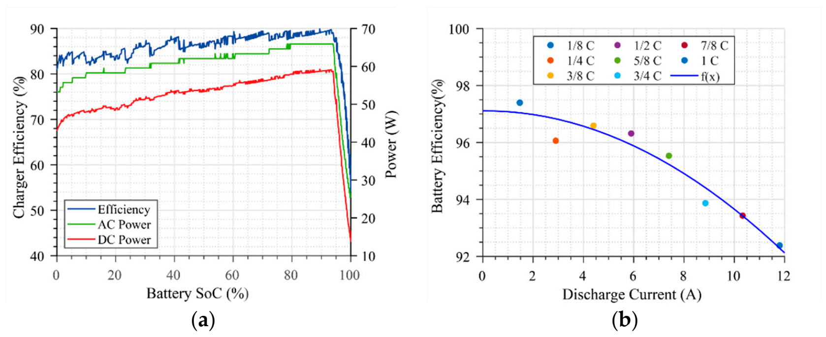
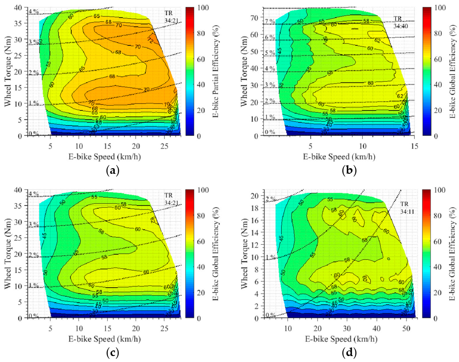
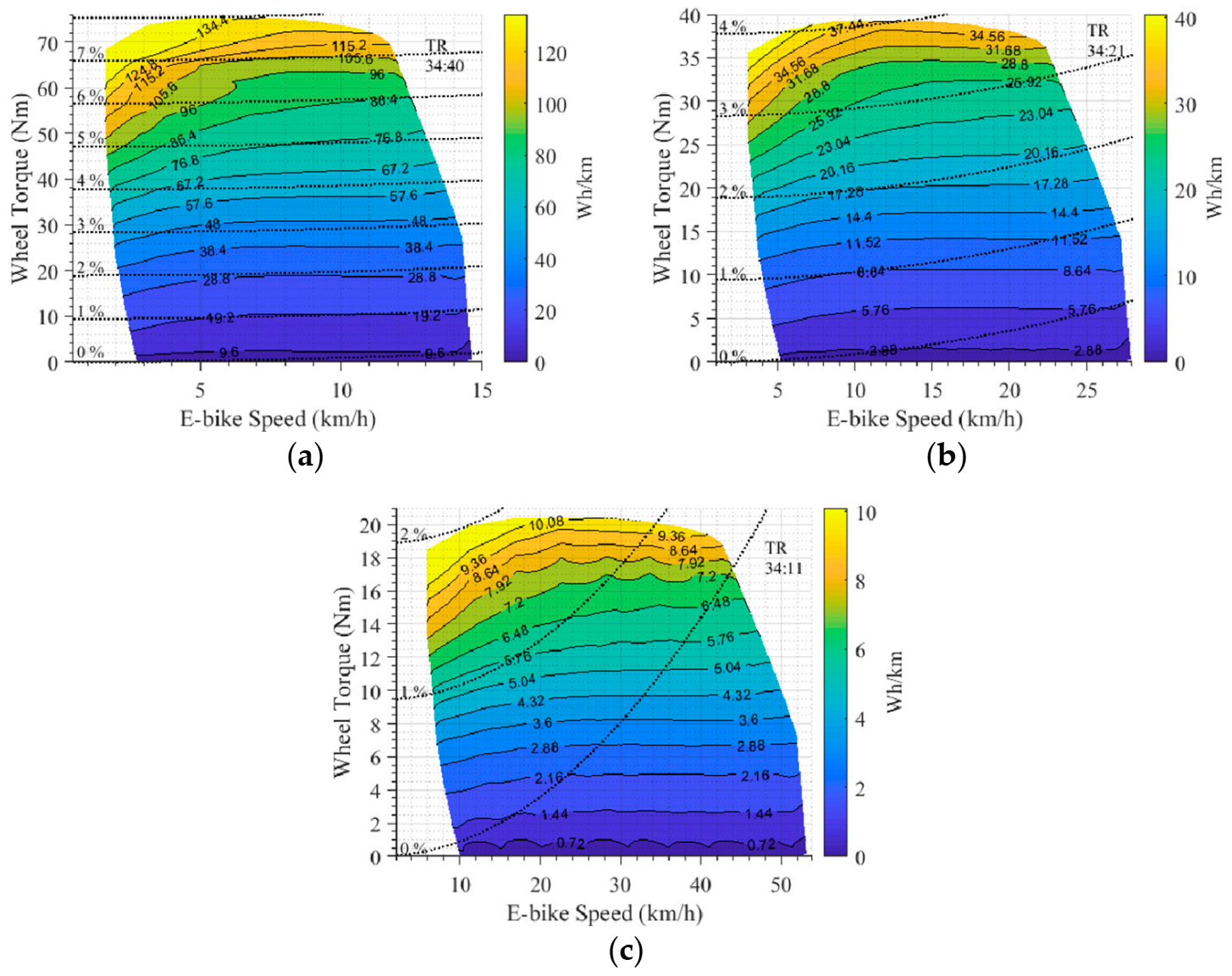
The global efficiency map of a mid-drive motor e-bike was generated through the integration of the efficiency of its subsystems. This showed that the system does not have a punctual efficiency, but that this aspect varies continuously throughout all its operating range. The components characterization results demonstrated that every subsystem has a significant impact on the overall efficiency, this aspect being highly determined by the CMRGs sub-system, which has the greatest variation (between 20% and 80%). In addition, the system efficiency is highly affected by the chain drive, with efficiency varying between 70% and 98% depending on chain tension. Components such as the battery (efficiency varying between 88% and 97% according to the discharge current) and the charger (which has 85.7% total efficiency) have fewer impacts on the system’s efficiency. The characterization of the per unit of distance energy consumption facilitates the system’s range enhancement. By contrasting the per unit of distance energy consumption maps, it is possible to determine that the range of the system is extended by using the chain transmission ratios that increase speed. Likewise, these maps show that, for the same slope, the greater the speed the greater the energy consumption due to the drag force increase.
It was found that in order to increase the system’s range, focusing on its per unit of distance energy consumption is more relevant than focusing on its operational efficiency. This happens because, whilst the operational efficiency evaluates the system’s internal components performance alone, the per unit of distance analysis considers both the internal components’ performance as well as the system interaction with external forces, making it possible to completely identify the use given to the energy to be transformed into displacement.
The efficiency differences and per unit of distance energy consumption analyses are contrasted in the maps that represent them (
Figure 7 and
Figure 8). Where the best efficiency operational points are generated at high speeds and medium to high torques, while the best energy consumption points per unit of distance are generated at low torques, regardless of speed.
Driving strategies performance were characterized for their energy consumption and average speed, observing that, for the driving strategies comparative results, the driving strategy proposed in this article equals or increases the range of the system in contrast to the driving strategies commonly used by untrained cyclists [
37,
38].
This article is presented as a new advance in the field of electric bicycle range optimization by carrying out a complete analysis of the variables affecting an e-bike performance and electrical consumption. Likewise, the algorithm proposed is presented as a tool that offers suggestions to the cyclist to enhance the system’s range from the selection of the chain transmission ratio and the level of assistance according to the slope. The developed research differs from the previous methodology (developed by De la Iglesia et. al. [
17] and used to increase the range of electric bicycles through neural networks), by implementing the mathematical model of the system and the performance of the efficiency of its components to generate the optimal selection of the assist level and the chain transmission ratio.
Improving the electric bicycle range is a complex matter, since it encompasses multiple variables, such as the desired travel time, the route profile, the power delivered by the cyclist, the wind speed, among others, making the best way to ride a bicycle not a single solution. Future work is expected to implement road tests and incorporate more variables to the problem, covering objectives such as traveling a variable slopes route in a given time by minimizing energy consumption or determining the system operation to complete a route by using the remaining capacity of the battery.


