Article

Comparative Study on Hybrid Excitation Flux Switching Motors without and with Variably Magnetizable Permanent Magnets for Electrified Vehicle Propulsion

Department of Electrical and Mechanical Engineering, Nagoya Institute of Technology, Nagoya, Aichi 466-8555, Japan
*
Author to whom correspondence should be addressed.
World Electr. Veh. J. 2021, 12(2), 58; https://doi.org/10.3390/wevj12020058
Submission received: 3 March 2021 / Revised: 24 March 2021 / Accepted: 30 March 2021 / Published: 2 April 2021
(This article belongs to the Special Issue Novel Permanent Magnet Machines and Drives for Electric Vehicles)

Abstract

:
A demand for high efficiency traction motors has been accelerated by the promotion of electrified vehicles, such as battery and fuel cell electric vehicles. As a part of development of the high efficiency traction motor, this paper reports a comparative study on two kinds of hybrid excitation flux switching motors (HEFSM) as a variable flux machine. One is the conventional HEFSM, which consists of a stator with constantly magnetized-permanent magnets, field excitation coils (FECs) and three-phase armature windings, and a rotor with salient poles like a switched reluctance motor. The other is a HEFSM employing variably magnetizable-permanent magnets (VM-PMs) that replace a part in the FEC slot area in the conventional one. Based on the variable magnetization nature of VM-PMs, the latter HEFSM promises that the replacement of magnetomotive force (mmf) of FECs with that of the VM-PMs makes the motor efficiency better at both low- and high-speed under the low-torque condition, that is, at both urban driving or highway cruising. To verify that, finite element analysis- (FEA)-based design simulations, as well as experimental performance evaluations for the two kinds of HEFSM, were conducted under reasonable dimensional and electrical constraints. As a result, it is shown that the latter HEFSM can achieve higher motor efficiency at the low-torque and high-speed region while keeping the motor efficiency at the low-torque and low-speed region.

1. Introduction

Currently, most electrically driven vehicles, such as hybrid, battery, and fuel cell electric vehicles, implement interior permanent magnet synchronous motors (IPMSMs) as main traction motors because of their high efficiency, high torque, and power density [1,2,3]. Basically, IPMSMs have a constant air gap flux density since their permanent magnets (PMs) work as a constant magnetomotive force (mmf) source. Therefore, it is impossible to realize both the desirable large and low air gap flux density separately required in the low-speed and high-speed region, respectively. In order to solve this issue and suppress their back-electromotive force (back-emf) and iron loss at the high-speed region, flux weakening control is generally applied. Meanwhile, flux weakening current (negative d-axis current) causes an increase in copper loss, which leads to a deterioration in motor efficiency. This means that it is difficult to achieve high efficiency and high-power density over the entirety of the operating range. To overcome this problem, a hybrid excitation flux switching motor (HEFSM) has received much attention in automobile propulsion applications as a kind of variable flux motor (VFMs) [4,5,6,7,8]. The HEFSM typically employs constantly magnetized-permanent magnets (CM-PMs) and field excitation coils (FECs) on the stator body as two different field mmf sources. They not only work as a VFM thanks to an adjustment of the mmf of FECs, but also have the following features: (1) ease of cooling of all active components, such as armature windings, FECs, and PMs, because all of them are located at stator body and (2) being mechanically robust for high-speed operation owing to simple and rugged rotor structure. As an example, the HEFSM as a VFM has realized better motor efficiency at light-load and high-speed operating regions while keeping the torque and power densities comparable with the IPMSM installed on Toyota third-generation Prius [8].
As a next goal in our project, an object of comparison for designing a HEFSM was reconsidered from the third-generation Prius’ IPMSM to one from the fourth-generation Prius [1,9]. The target specifications were updated accordingly, by which the maximum speed, power, and torque were set to 17,000 r/min, 53 kW, and 163 Nm, respectively. Stator outer diameter and motor axial length, including end-coil as overall motor dimensional restrictions, were also reset to 215 mm and 117.5 mm, respectively. After updating the target specifications and the overall machine dimensions, another HEFSM design was built and experimentally tested [9]. As a result, unfortunately, the motor efficiency measured of the new HEFSM was much lower than that of the fourth-generation Prius’ IPMSM. In particular, at the low-load and low-speed frequent operating area corresponding to the urban driving situation of vehicles, the main reason why was due to a large copper loss, whereas it was because of a large iron loss at the low-torque and high-speed frequent operating area corresponding to highway cruising situation. As one of the possible solutions to mitigate the motor efficiency degradations mentioned above, a new HEFSM with variably magnetizable-permanent magnets (VM-PMs) replacing a part of the FECs was considered. This was because, based on the variable magnetization characteristic of VM-PM, which is well-known [10,11,12,13], the HEFSM with the VM-PMs would promise that the replacement of mmf of FECs with that of the VM-PMs made the motor efficiency better at both the low- and high-speed under the low-torque condition, that is, at both the urban driving and high-way cruising situation.
In this paper, a comparative study on the conventional HEFSM without the VM-PMs and the new HEFSM with one replacing a part of FECs from the conventional HEFSM is presented aiming at how it effects motor efficiency improvement. The new HEFSM enables not only a great reduction of copper loss by making continuous excitation of the FECs unnecessary thanks to strengthening the magnetization state of VM-PMs, but also a great reduction of back-emf and iron loss by weakening the magnetization state of VM-PMs. After finite element analysis (FEA)-based design and simulation are conducted, experimental studies on performance evaluation results using a fabricated test motor are demonstrated. As a result, the new HEFSM achieves higher motor efficiency at the low-torque and high-speed region while keeping the motor efficiency at the low-torque and low-speed region.

2. Machine Topology and Test Result Analysis of the Conventional HEFSM

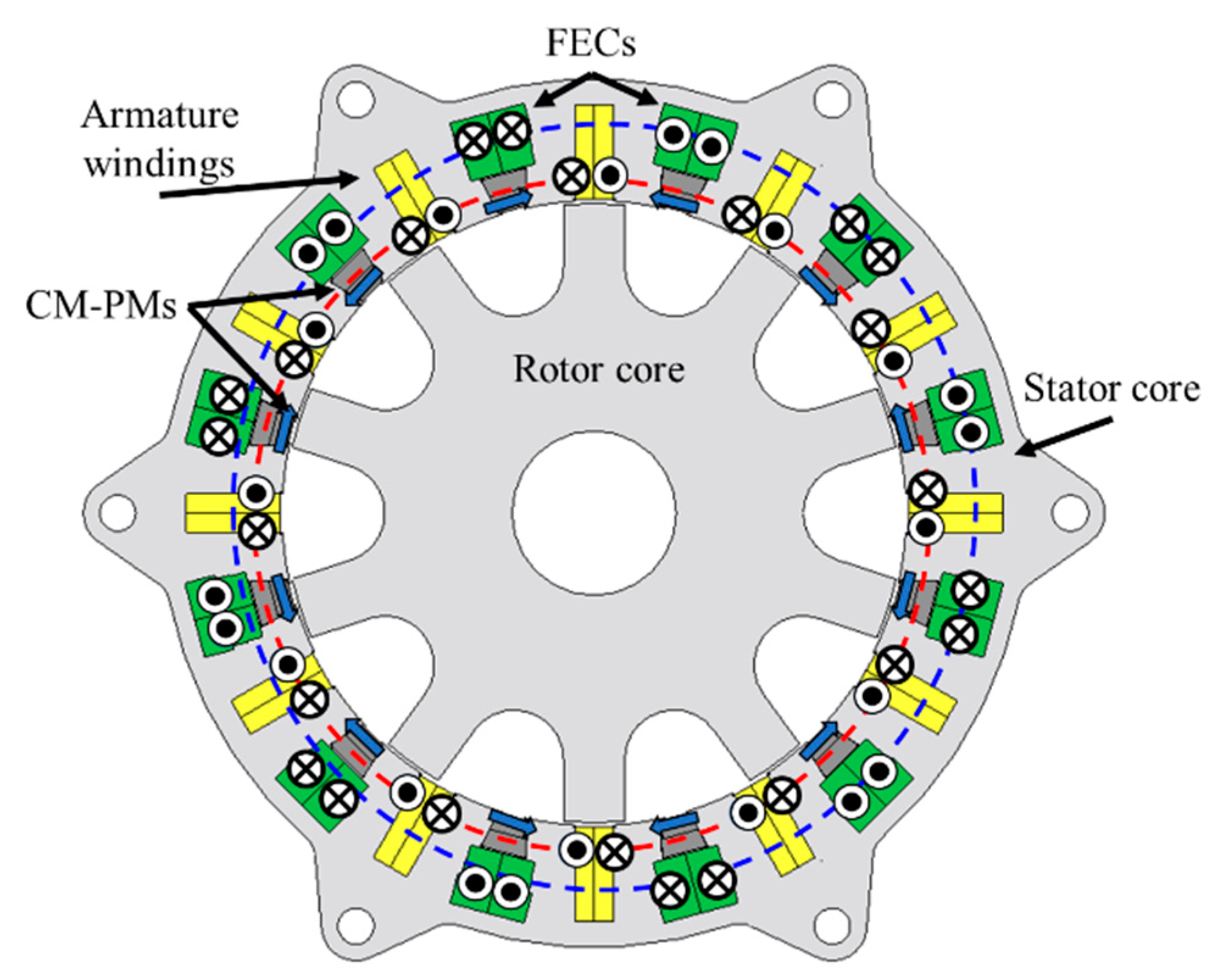
2.1. Machine Topology

Figure 1 is a sectional view of the conventional HEFSM [9]. This machine consists of the stator with 24 coil slots and the rotor with 10 salient poles. As apparent from the figure, all active parts, such as the three-phase armature windings, CM-PMs, and FECs, are located at the stator body. The rotor is made of only the laminated electromagnetic steels and is suitable for high-speed drive applications like a switched reluctance motor. Depending on the arrangement of CM-PMs on the stator, the HEFSMs have different aspects and are roughly classified into three types: One with CM-PMs placed at the inner portion of the FEC slots, another with them placed at the outer portion, and the last with them placed at the middle [14]. Although the first type selected in this study as the conventional HEFSM shown in Figure 1 requires the CM-PMs with higher coercive force compared to the other two types to avoid irreversible demagnetization, it is superior in terms of the maximum torque capability and the motor efficiency at low-speed and light-load operating region.

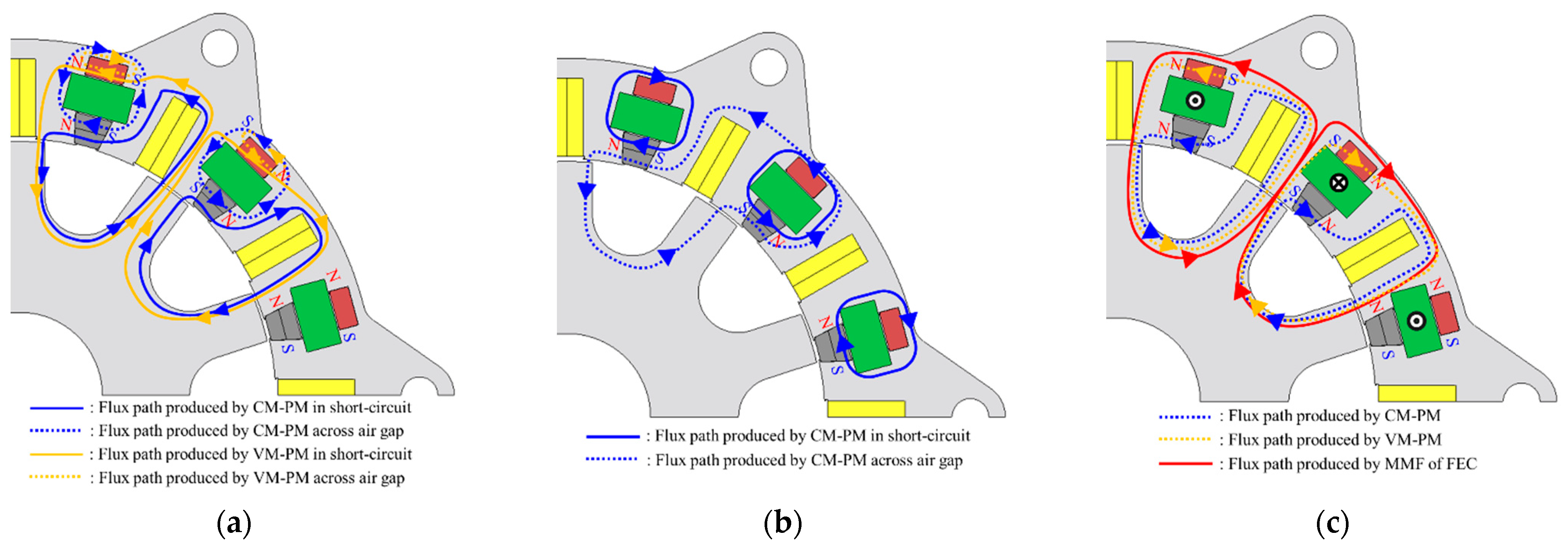
2.2. Basic Working Principle

Figure 2 illustrates schematic diagrams of field flux paths produced by the CM-PMs and the mmf of FECs with and without excitation. In the case of no FEC excitation, as shown in Figure 2a, only a little PM flux flows across the air gap, whereas most of the PM flux is in short-circuit path via the back yoke outside of the FECs. The results is that the field flux density at the air gap is considerably low at no FEC excitation, which makes it possible to reduce iron loss, as well as the back-emf, at the high-speed operation. On the other hand, Figure 2b shows the field flux path at the field strengthening achieved by the FEC excitation. The field flux generated by the FECs does not pass through the CM-PMs but flows into a flux path indicated by a red line as shown in the figure. In addition, the CM-PM flux path changes from one in short-circuit to one across the air gap. Thus, the conventional HEFSM works as a VFM by adjusting the FECs excitation.

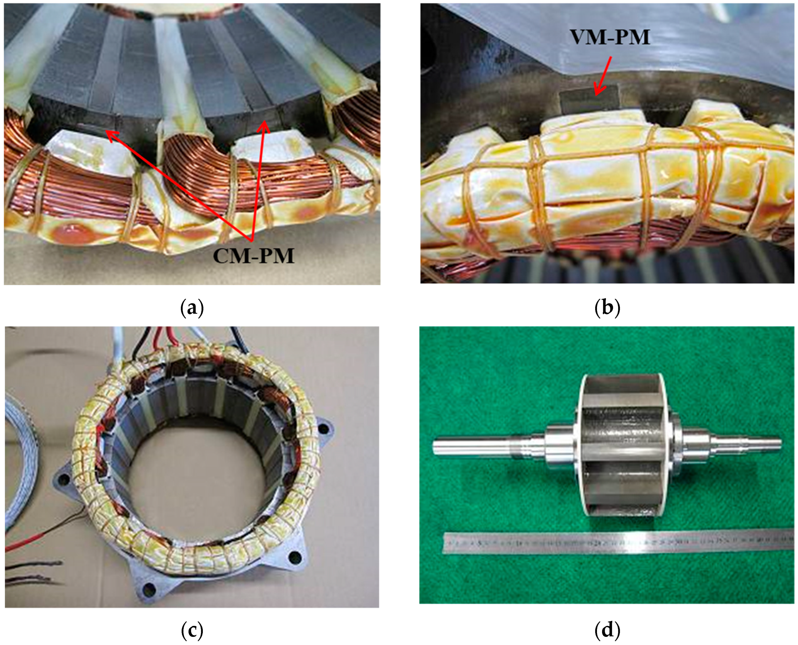
2.3. Fabricated Machine and Test Result Analysis

As mentioned earlier, the object of comparison for designing the conventional HEFSM in our project was the IPMSM installed on the fourth-generation Prius [1]. Table 1 shows the design constraints and target performances to be considered. Most of the items in the table are determined with reference to the specifications of the IPMSM. The total motor axial length including the end-coil length, stator outer diameter, airgap length, and total weight of CM-PMs used are limited or fixed as shown in the table. Electrical limitations and thermal restrictions are also set as follows, assuming that the same inverter and the same cooling system as the target IPMSM drive system are applied, respectively [15]. The target drive performances, such as the maximum speed, power, and torque are set to 17,000 r/min, 53 kW, and 163 Nm, respectively.
For the design constraints and target specifications, the conventional HEFSM has been designed and fabricated. Although the details about the design process and the fabricated test motor have been reported in [9], only one point to be emphasized is that the CM-PMs are divided into two layers using two different types of PM, respectively. One, arranged far from the airgap, has high remanence and low coercive force aiming to reduce copper loss. The other, located near the airgap, has relatively low remanence and high coercive force to avoid the irreversible demagnetization of the CM-PMs. The measured maximum power and torque of the test motor are 64.9 kW and 164.3 Nm, which achieve the targets of 53 kW and 163 Nm, respectively. However, a remaining issue is that the motor efficiencies measured at frequent operating points have been significantly poor.
Table 2 shows the 3D-FEA computed and the measured motor efficiencies and losses of the designed and fabricated conventional HEFSM under the frequent operating points as the target traction motor. For the 3D-FEA based motor efficiency predictions, JMAG-Designer ver. 19.0.05, JSOL Corporation was used. ηm means the motor efficiency. Pca and Pcf are copper losses consumed during operation at temperature of 100 °C in the armature windings and the FECs, respectively. Pi is the iron loss. The measured iron loss was obtained as a residual loss by subtracting the motor output power, the sum of copper losses (Pca + Pcf), and the mechanical loss from the motor input power. In the measurements and the 3D-FEA predictions, the motor was operated by the maximum motor efficiency control for the given operating condition based on selecting an optimum current combination between d-, q-axis current, Id and Iq, and FEC current If, as shown in Table 3. It can be found from Table 2 that the motor efficiencies measured were significantly poor and less than 90% at all frequent operating points. First, at the low-speed region below 2500 r/min, an extra loss with respect to the IPMSM was obviously Pcf. Therefore, one of the countermeasures for the motor efficiency improvement would be an increase in the field flux produced by the CM-PMs under no FEC excitation. Second, it could be observed that the measured Pcf were higher than those computed by 3D-FEA. This is because the optimum current combination is different between the measurement and 3D-FEA prediction, as shown in Table 3. In particular, the optimum FEC current If beyond 4000 r/min in the measurement becomes significantly higher than that in the 3D-FEA evaluation to achieve higher motor efficiency by reducing iron loss. As can be seen in Table 2, this yields the increase in Pca due to an increase in the field weakening current Id, as shown in Table 3. Although the essential problem is inaccurate iron loss prediction in the 3D-FEA at the design stage due to no consideration of time-consuming factors such as PWM harmonics and stray load losses generated in motor components other than the iron core, one of the countermeasures would also be an increase in the field flux produced by the CM-PMs under no FEC excitation. However, too much increase in the field flux produced by the CM-PMs would not maintain the motor efficiency improvements, both in the low-speed and the high-speed region. Therefore, a design study on a new HEFSM employing VM-PMs replacing the mmf of FECs will be conducted in the next chapter.

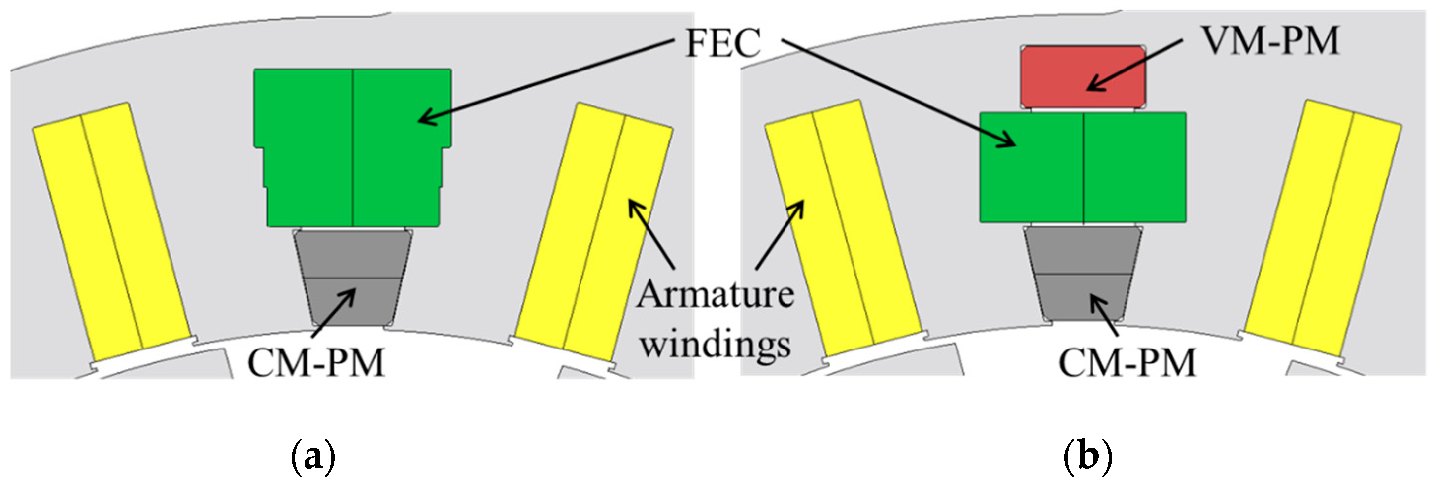
3. Rudimentary Design of the New HEFSM with VM-PMs

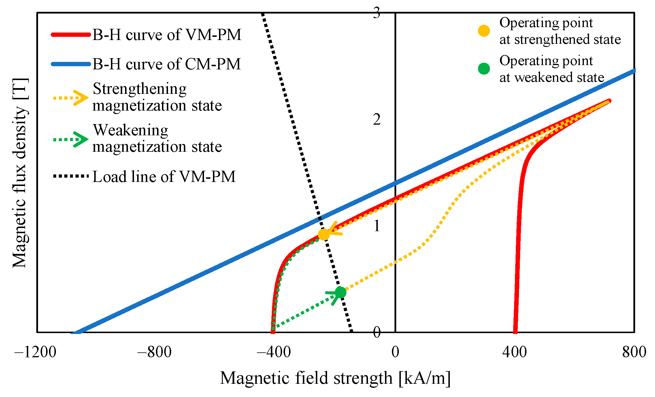
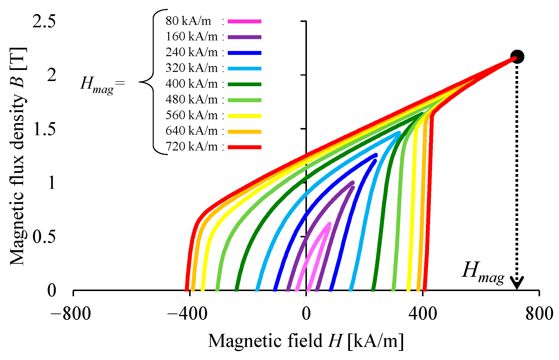
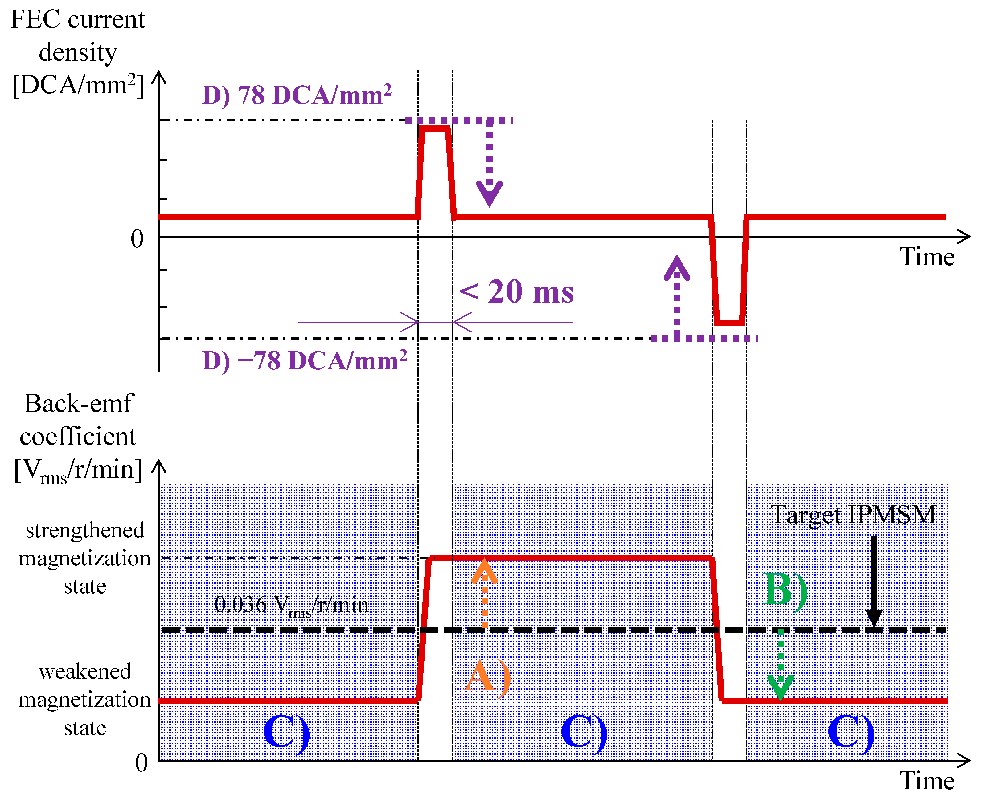
3.1. Magnetization State Control of VM-PMs by FEC Current Injection

Figure 3 depicts a schematic diagram of B-H curves of a CM-PM and a VM-PM. Compared with a sintered Nd-Fe-B magnet used as a CM-PM, a PM with lower coercive force and higher residual flux density is suitable for a VM-PM from a viewpoint of changing the magnetization state with a reasonable magnetic field and strengthening the field flux density at airgap. In consideration of the above, in this study, a newly developed Nd-Fe-B type magnet with a lower coercive force, NL720MC20 supplied by TDK Corporation (Narita, Chiba, Japan) was selected as a VM-PM. The cost of VM-PM is about the same as a current commercial sintered Nd-B-Fe magnet. Figure 4 is the measured B-H curves of NL720MC20 at 20 °C for different magnetizing magnetic field Hmag. The B-H curve measurements were done every 80 kA/m of Hmag and repeated after degaussing by thermal treatment. It can be seen from the figure that the residual flux density and the coercive force at 20 °C after applying full magnetization of Hmag = 720 kA/m were Br = 1.25 T and HcB = 411 kA/m, respectively.
The magnetization state control of VM-PMs in the new HEFSM should be done anytime it is required. To change the magnetization state, a quasi-impulse current was applied to the FECs. By applying a quasi-impulse FEC current in the magnetizing direction, a magnetizing magnetic field was applied to the VM-PMs in its orientation direction. The magnetization state of VM-PMs varies, as shown by the dotted orange line in Figure 3, so that it is strengthened. Contrarily, by applying a quasi-impulse FEC current in the demagnetizing direction, a demagnetizing magnetic field is applied to the VM-PMs in the reverse direction of its orientation. The magnetization state of VM-PMs varies, as shown by the dotted green line in Figure 3, so that it is weakened. In this study, an extremely-short duty maximum current density of FECs when supplying a quasi-impulse current was limited to be less than three times of a normal-short duty maximum current density.

3.2. Design Criteria

The new HEFSM employing VM-PMs was designed as an effective countermeasure against the motor efficiency improvement in both the low- and high-speed region, in which a part of the mmf of FECs in the conventional HEFSM was simply replaced with a VM-PM as a rudimentary design study. In the low-speed region, the amount of armature and FEC current required for a given torque command can be reduced by strengthening the magnetization state of VM-PMs, whereas, in the high-speed region, iron loss as well as back-emf in an open circuit can be decreased by weakening the magnetization state of VM-PMs. In principle, a selection of VM-PMs and ways to control their magnetization state according to a specified whole motor operating area should be examined and designed. However, in this rudimentary study, two design criteria were set as following manners. One was that the back-emf coefficient in open circuit at the strengthened magnetization state of VM-PMs became higher than that of the IPMSM from a standpoint of copper loss reduction in the low-speed and low-torque region. The other was that the back-emf coefficient in open circuit at the weakened magnetization state of VM-PMs could be sufficiently reduced compared with the IPMSM from a viewpoint of iron loss reduction in the high-speed and low-torque region. The design criteria are summarized below, including other two important criteria to be considered for designing the new HEFSM with VM-PMs.
  • The back-emf coefficient in open circuit at the strengthened magnetization state of VM-PMs is greater than that of the IPMSM;
  • The back-emf coefficient in the open circuit at the weakened magnetization state of VM-PMs is enough to be smaller than that of the IPMSM;
  • The magnetization state of VM-PMs never changes, except at the instant when a quasi-impulse current is applied to the FECs;
  • The target magnetization change rate can be achieved within the limitation of FEC current density less than three times of a short duty maximum current density.
Figure 5 illustrates detailed specifications for the four criteria above. For (A) and (B), the back-emf coefficient of the IPMSM as the object of comparison in this study is 0.036 Vrms/r/min. For (C), the magnetization state of VM-PMs must be kept during the normal operation, including the normal field strengthening control by the FECs, within the normal-short duty maximum current density of 26 DCA/mm2, as listed in Table 1. For (D), the tree times of the short duty maximum current density of FECs is ±78 DCA/mm2. In addition, the pulse width of quasi quasi-impulse FEC current. including the transient response time, is set to be less than 20 ms considering the allowable temperature rise of FECs and the elimination of uncomfortable driver’s feeling caused by torque variation [16].

3.3. VM-PM Arrangement Design

The CM-PM was placed at the inner of FEC slots in terms of higher maximum torque capability and higher motor efficiency at the low-torque operating region. In the new HEFSM design, the CM-PM kept the location, the shape, and the material the same as the conventional HEFSM for the purpose of revealing how the VM-PM effectively contributed to motor efficiency improvement. With this CM-PM location, two types of VM-PM arrangements, as shown in Table 4, were compared and investigated. One was the VM-PM inner arrangement in which the VM-PM was placed between the CM-PM and the FEC slot. The other was the VM-PM outer arrangement in which the VM-PM was placed outside the FEC slot. The figures in the table also include flux paths for each VM-PM arrangement. The blue- and orange-colored lines show the CM-PM and the VM-PM flux paths, respectively, when the maximum field strengthening FEC current and the maximum armature current were applied to the motor for the normal maximum torque operation. The red- and green-colored lines represent the flux paths produced by the mmfs of the FECs and the armature windings, respectively. In the VM-PM inner arrangement, only two fluxes, that is, the fluxes caused by the mmfs of the FECs and the armature windings, overlap each other at the stator tooth on the left side of the FEC slots, shown by the blue-colored ellipsoid. In contrast, in the VM-PM outer arrangement, three fluxes flowed together at the whole of the stator tooth on the left side of the FEC slots, highlighted by the red-colored ellipsoid, which resulted in severe magnetic saturation. As reported in [9], it degraded the maximum torque capability. The figures in the table also depict the directions of the magnetic fields, produced by the mmf of FECs in each VM-PM arrangement, with the red arrow when the field strengthening FEC current was applied to the motor under high-load operation. In the VM-PM inner arrangement, the magnetic field generated by the mmf of FECs became a demagnetizing magnetic field with respect to the VM-PM. Therefore, the VM-PM inner arrangement required a PM with relatively high coercive force to ensure demagnetization durability of the VM-PM during high load operation. In the VM-PM outer arrangement, on the other hand, the magnetic field produced by the mmf of FECs worked as a magnetizing field with respect to the VM-PMs so that a PM with relatively low coercive force could be employed. In order to make it easier to satisfy the design criteria, especially C) and D), the VM-PM outer arrangement was selected in this study in terms of demagnetization durability during the high-load operation and suppressing the required quasi-impulse FEC current density for changing magnetization state of VM-PMs that depend on the coercive force of VM-PM.

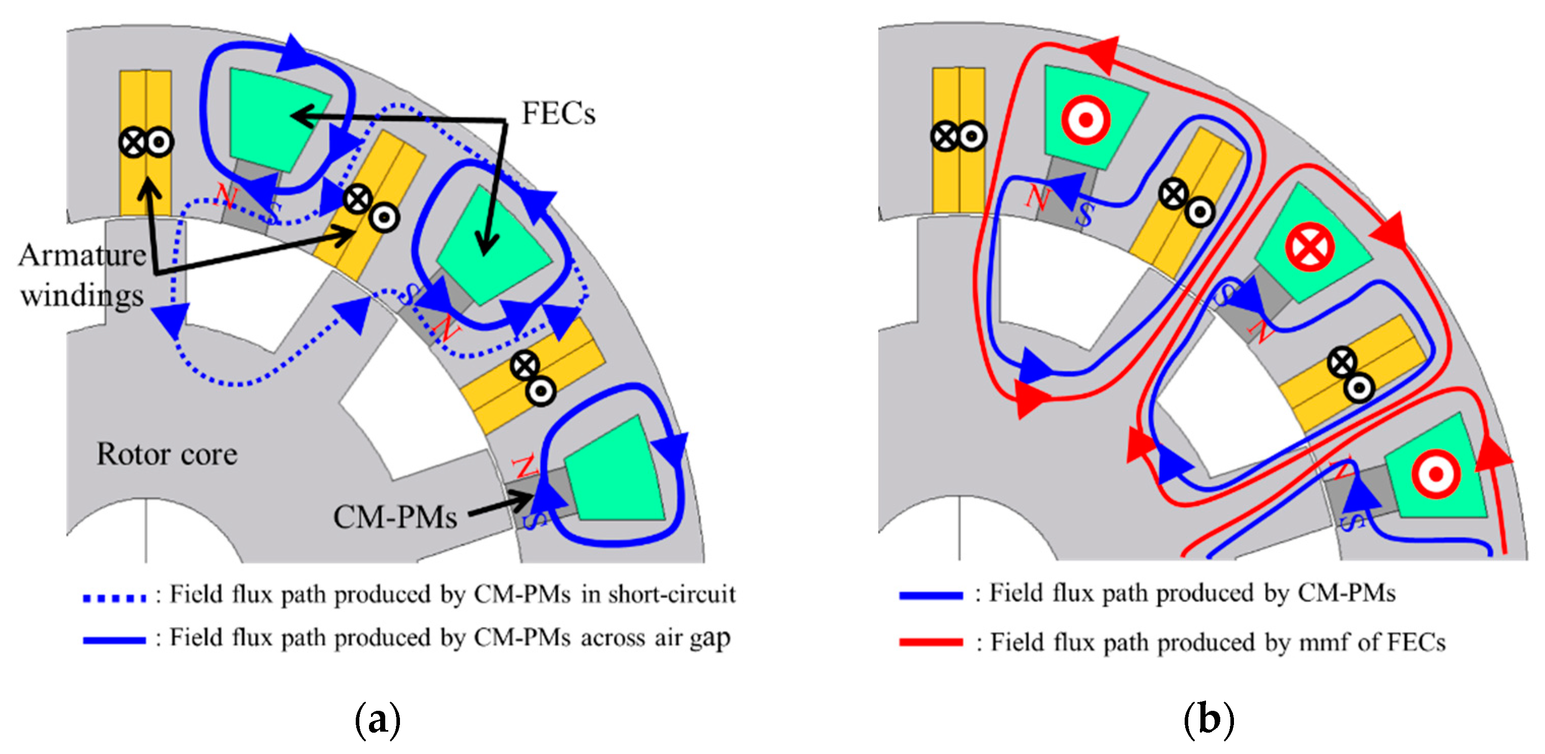
3.4. Design Results and Basic Working Principle of the New HEFSM with VM-PMs

Except for the shape of armature winding slot, as well as the material and the shape of CM-PM, other stator core shapes, including that of the VM-PM, were designed using 3D-FEA (JMAG-Designer, ver. 19.0.05, JSOL Corporation, Tokyo, Japan) by trial and error to satisfy the design criteria from (A) to (D) under the design constraints listed in Table 1. The rotor was the same as that used in the fabricated conventional HEFSM [9]. Figure 6 shows a comparison of the stator main parts between the conventional HEFSM and the newly designed one with the VM-PMs. Table 5 shows the specifications of the newly designed HEFSM with VM-PMs. Note that the filling factors for the armature windings and the FECs were set to 0.7 on the assumption that high filling factor windings using flat shape rectangular wires were employed. The resultant maximum current densities, as well as resistances in both the armature windings and the FECs, were also calculated under the same assumption. As a part of the FEC slot was replaced with the VM-PMs, the maximum ampere-turns per slot of the new HEFSM was lower than that of the conventional HEFSM.
Figure 7 illustrates flux paths produced by the CM-PM, the VM-PM, and the mmf of FEC under different VM-PM magnetization with and without FECs excitation. Figure 7a shows the flux paths under no FEC excitation and the strengthened magnetization state of VM-PMs. In this case, the short-circuit path of both the PMs, via the back yoke outside of VM-PM, was prevented from severe magnetic saturation because the flux produced from VM-PM was added to one produced from CM-PM. This resulted in a large amount of total PM flux passing through the airgap without any FEC excitation. As can be seen from this figure, the CM-PM and the VM-PM in this machine are in a magnetically parallel configuration. Consequently, the copper losses in the armature windings, as well as in the FECs at the low-speed and light-load operating region, would decrease in comparison with the conventional HEFSM. Figure 7b represents the flux paths under no FEC excitation and the weakened magnetization state of VM-PMs. The amount of CM-PM flux passing through the airgap became small because most CM-PMs fluxes were in a short-circuit path flowing from their N-pole to S-pole via the magnetically unsaturated back yoke. This contributed to reductions of back-emf, iron loss, and flux weakening current at high-speed and low-load operating range. Figure 7c illustrates the flux paths under the FEC excitation and the strengthened magnetization state of VM-PMs. All field fluxes produced from the CM-PM, the VM-PM, and the mmf of FECs passed through the airgap. The total amount of flux linkage of armature windings could be significantly increased, and therefore, the field strengthening by the VM-PM and the mmf of FECs worked for producing high torque and reducing the copper loss of armature windings at the low-speed and the high-load operating region. Accordingly, the new HEFSM with VM-PMs would expand high efficiency operating area over the whole operating range.

4. Experimental Results Using Fabricated Newly Designed HEFSM with VM-PMs

4.1. Test Motor Specifications

Figure 8 shows photographs of the newly designed HEFSM built to validate the design result. As mentioned in Section 3.4, the new HEFSM was designed on the assumption that high filling factor windings using flat shape rectangular wires were employed for both the armature windings and the FECs. As can be seen from Figure 8, however, round wires were actually used in both the fabricated conventional and new HEFSMs instead of the high filling factor coils because of time and budget limitations. As a result, the filling factors of both coils went down so that the related values, such as the maximum current densities, the measured resistances of armature windings/phase, and one of the FECs, increased, as listed in Table 6. Furthermore, the total motor axial length reached 128 mm, which also exceeded the target of 117.5 mm. The utilization of high filling factor rectangular coils promises reductions of the maximum current densities and the total motor axial length based on our previous fabrication of HEFSM [8].

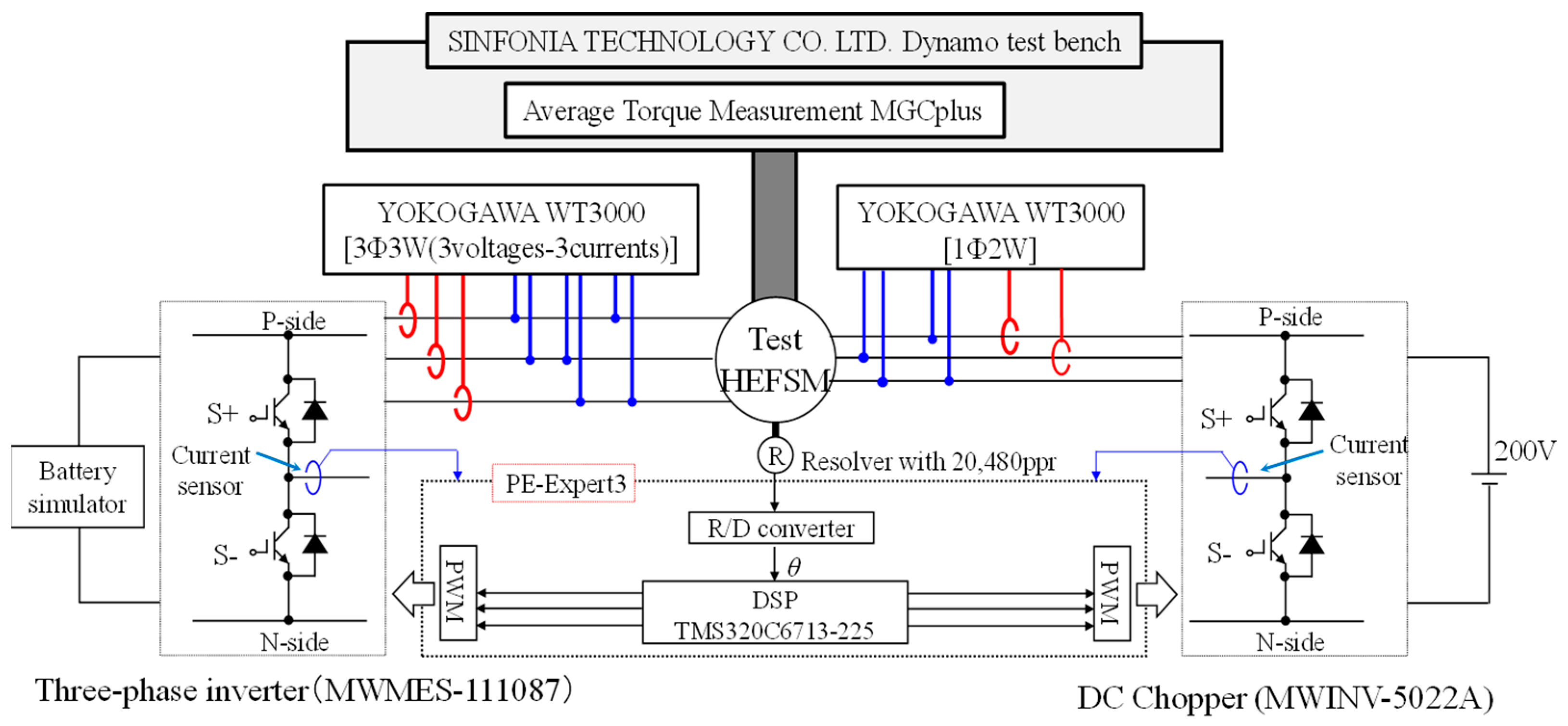
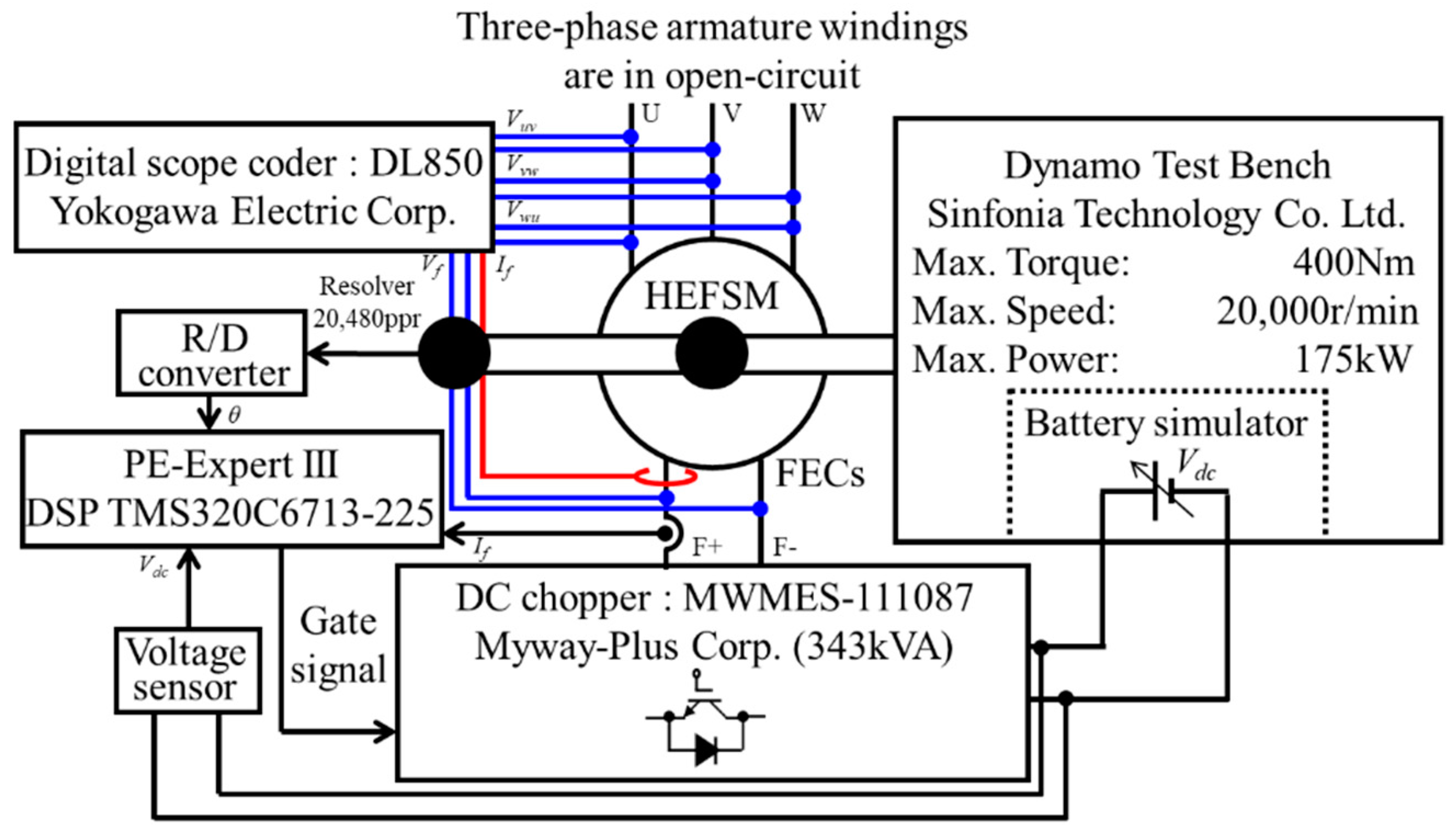
4.2. Experimental Setup

Figure 9 is the configuration of experimental setup for testing the fabricated new HEFSM under normal operation. As a constant speed load, a high-speed and large capacity dynamo setup manufactured by SINFONIA TECHNOLOGY Co., Ltd. (Toyohashi, Aichi, Japan) was coupled with the test motor. The dynamo setup could maintain the motor speed constant in the range of 0 to 20,000 r/min, and evaluate the motor output power and the motor torque up to 175 kW and 400 Nm, respectively. A torque meter, MGCplus manufactured by HBM Corporation (Darmstadt, Germany) was used for measuring the average output torque. The rotor position information was acquired using a resolver with 20,480 ppr through an R/D converter made by TAMAGAWA SEIKI Co., Ltd. (Nagano, Japan). A DSP-based digital controller, PE-EXPERT III manufactured by Myway-Plus Corporation, was used. A three-phase inverter (MWMES-111087: Myway-Plus Corporation, Yokohama, Japan, rated capacity 343 kVA) was employed to apply the three-phase armature currents to the test motor. It could supply up to 450 Arms of current, and its DC-bus voltage was controlled to an appropriate voltage in the range of 200 V to 600 V, depending on the speed and load conditions by the battery simulator integrated into the dynamo setup. Another three-phase inverter (MWINV-5022A: Myway-Plus Corporation, Yokohama, Japan, rated capacity 50.6 kVA) was used as a DC chopper to excite the FECs and could be fed a maximum current up to 146 DCA, and its DC-bus voltage was fixed at 200 V. Up to the base speed, pulse width modulation (PWM) control with the switching frequency of 12.5 kHz was implemented for vector current control of the three-phase armature windings. In the operating region exceeding the base speed, the control method was switched to the six-step voltage control. In accordance with given operating conditions, an applied voltage lead angle was adjusted in the six-step voltage control. The currents, voltages, and input powers to the armature windings and the FECs were measured with the digital power meter WT3000 made by Yokogawa Electric Corporation (Tokyo, Japan).
On the other hand, when applying a quasi-impulse FEC current to change the magnetization state of VM-PMs, it is necessary to supply a large amount of electric power to the FECs instantaneously. In consideration of the capacity of our equipment, the system connection was changed, as shown in Figure 10. The battery simulator was used as the DC voltage source for the inverter (MWMES-111087) used as the DC chopper.

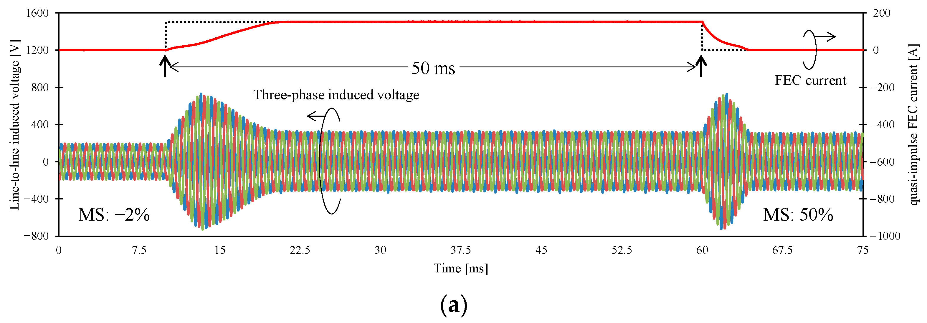
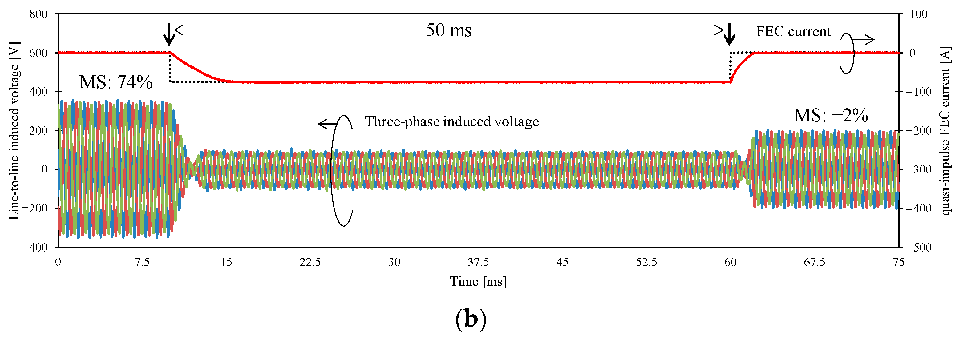
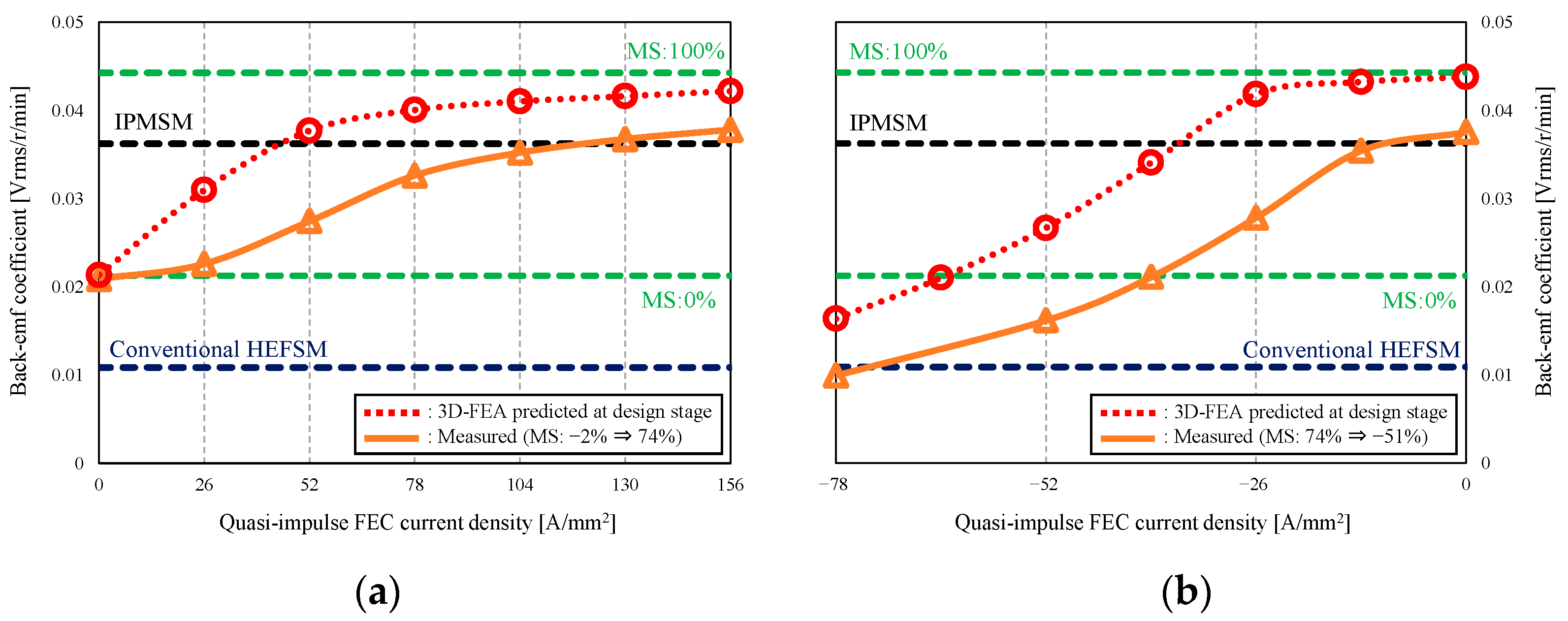
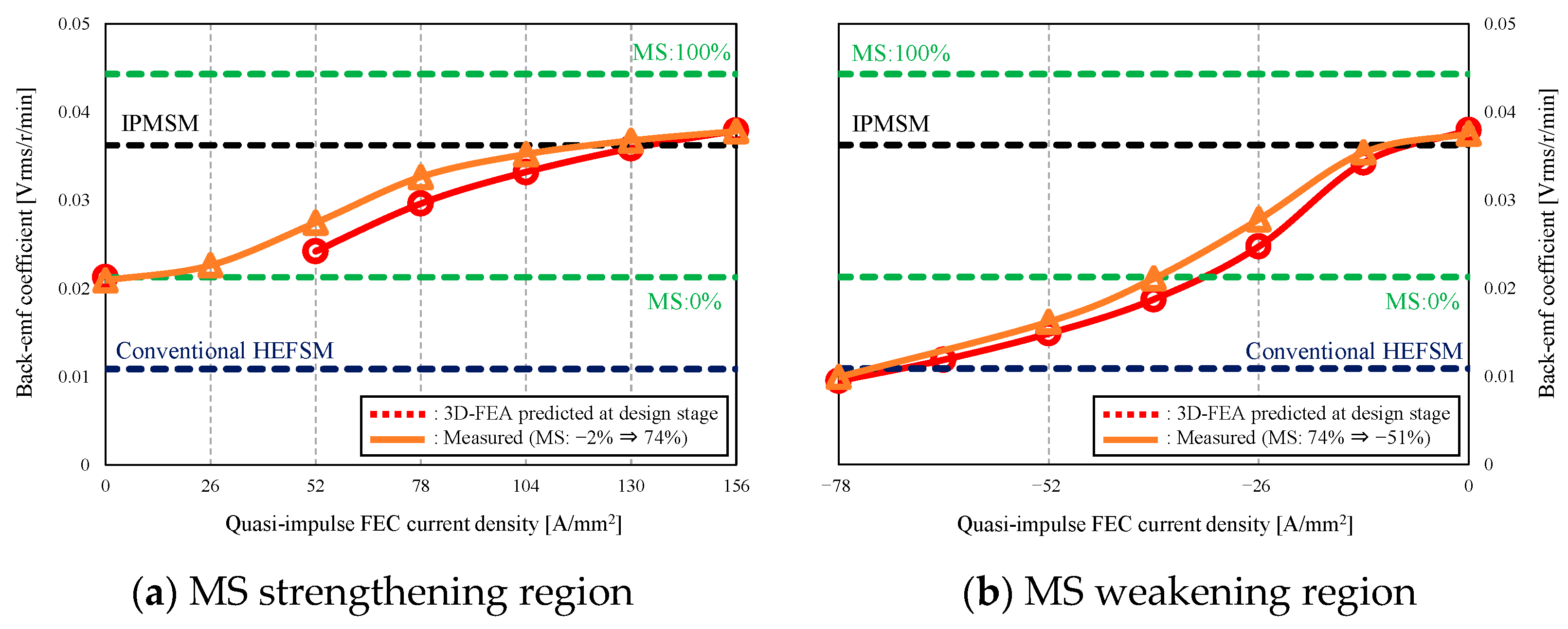
4.3. Variable Flux Capability by Changing Magnetizing State of VM-PM

By using the experimental setup shown in Figure 10, only the quasi-impulse FEC current was applied to the motor for changing the magnetizing state of VM-PMs during constant speed rotation at 6000 r/min while making the three-phase armature windings be in open-circuit. The speed set was considered in this study as a switching over speed just between the low- and the high-speed region. At the speed, a DC boost-up chopper inserted between the battery with 200 V and the DC-bus of inverter in a power control unit of the target vehicle would elevate the DC-bus voltage up to at least 300 V. Therefore, in this experiment, the DC-bus voltage of the DC chopper (MWMES-111087) for the FECs excitation was set to 300 V rather than 200 V for the normal operation.
Figure 11a,b demonstrate the measured FEC current waveforms for changing the magnetizing state (MS) of VM-PM from −2% to +50% and from +74% to −2%, respectively, as examples. In the figures, the measured three-phase induced voltage waveforms and MS values are also included. As an evaluation index of the magnetization state of VM-PMs after applying the quasi-impulse FEC current, back-emf magnetization rate is defined and given in,
Back-emf   magnetization   rate = K e K e _ 0 % K e _ 100 % K e _ 0 % × 100   [ % ] ,
where, Ke is back-emf coefficient in an open circuit after the quasi-impulse FEC current is applied and given in the following equation.
K e = V l N   [ V rms / r / min ] [ % ]
Vl is the fundamental component of measured line-to-line induced voltages in three-phase armature windings in RMS and N is the mechanical motor speed in r/min. In Equation (1), Ke_0% and Ke_100% are the back-emf coefficients at 0% and 100% magnetization state of VM-PMs, respectively, evaluated by 3D-FEA. The reference amplitude of FEC current in the strengthening magnetization, shown in Figure 11a, was set to 150 DCA, which corresponds to three times of the short duty maximum current density of 26 DCA/mm2 at the design stage, as listed in Table 5. According to our FEA simulation, a quasi-impulse FEC current must be applied to the motor more than one electrical cycle to guarantee a uniformity of the magnetization state of VM-PMs. At the speed of 6000 r/min, one electrical cycle in the test motor with 20 poles was 1 ms. As is apparent from Figure 11a, the rising and the falling times of FEC current were 11.5 ms and 4.5 ms, respectively. Thus, a total sum of the rising time, the falling time and 1 ms as one electrical cycle was 16.5 ms less than 20 ms, which met the design criteria (D). However, the reference amplitude of FEC current in the weakening magnetization, shown in Figure 11b, was set to −75 DCA, which corresponded to 1.5 times of the short duty maximum current density of 26 DCA/mm2, as listed in Table 5. It can be found from the figure that a total sum of the rising time, the falling time, and 1 ms as one electrical cycle was 9 ms, which also met the design criteria (D).
Figure 11. Measured FEC current waveforms for changing MS of VM-PM. (a) magnetization state change from −2% to +50%; (b) magnetization state change from +74% to −2%.
Wevj 12 00058 g011aWevj 12 00058 g011b
From Figure 11a,b, it is found that the amplitudes of line-to-line induced voltages in three-phase armature windings change before and after applying the quasi-impulse FEC current. These changes corresponded to the magnetization state change of VM-PM. Figure 12a,b are the measured and the 3D-FEA predicted back-emf coefficient curves in the MS strengthening and the MS weakening regions, respectively. The horizontal axis represents the FEC current density calculated based on the assumption that the test machine is fabricated using the high filling factor windings listed in Table 5. Figure 12a,b also include the measured back-emf coefficients of the conventional HEFSM and the computed one of the IPMSM as the object of comparison. The 3D-FEA predicted curves in the MS strengthening and the MS weakening regions were computed initially from 0% MS and 100% MS, respectively. In Figure 12a, the 3D-FEA predicted the magnetization state of VM-PMs when applying three times the short duty maximum FEC current density changes from 0% to +84% MS. This +84% MS realized a back-emf coefficient higher than that of the IPMSM, which met the design criteria (A). However, the measured one changed from −2% to +50% MS under the maximum FEC current density limitation, as also shown in Figure 11a. According to further experimental investigations, six times the short duty maximum FEC current density was required for achieving a back-emf coefficient higher than that of the IPMSM, as shown in Figure 12a. In the MS weakening region shown in Figure 12b, the MS change from +100 to 0% could be achieved in the 3D-FEA prediction at the design stage by applying 2.5 times the short duty maximum FEC current density. However, in the experimental test, the MS change from +74% to −2% could be realized by applying 1.5 times of the short duty maximum FEC current density, as also shown in Figure 11b. Thus, it was confirmed that the design criteria (B) could be also satisfied. The reason why the large error between the 3D-FEA predicted and the measured back-emf coefficients occurred will be discussed later.

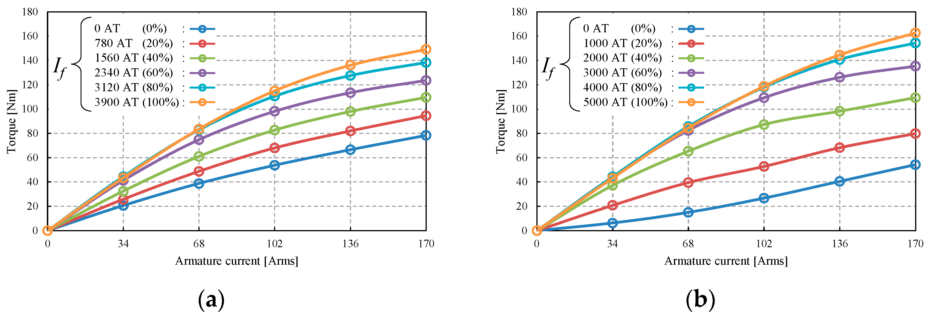
4.4. Measured Torque–Armature Current-FEC Current Characteristics

Figure 13a,b show the torque–armature current-FEC current characteristics measured in the newly designed HEFSM with VM-PM and the conventional HEFSM, respectively. In the measurements, the dynamo setup kept the motor speed constant at a low enough speed of 480 r/min. For both the machines, the armature current supplied was changed from 0 to the maximum inverter current of 170 Arms in 20% increments under the fixed current lead angle β = 0 deg. The FEC current fed also varied from 0 to the maximum current of 50 DCA in 20% increments. In the case of the newly designed HEFSM, the maximum mmf of FEC was 3900 AT/slot, whereas in the case of the conventional HEFSM, it was 5000 AT/slot, as appears in Table 5. At the maximum currents, the current densities in armature windings and FECs reached their maximum values of 26 A/mm2 as expected at the design stage. For the newly designed HEFSM with VM-PM, the MS of VM-PM was also a variable. As an example, Figure 13a demonstrates the torque–armature current-FEC current characteristics measured under +74% MS of VM-PM as its maximum achievable within the experimental limitation. The maximum torque at the maximum current of FEC and the maximum armature current was 150 Nm, which does not meet the target requirement of 163 Nm. On the other hand, the conventional HEFSM could achieve 163.4 Nm as the maximum torque at the same maximum current condition. This difference was caused by insufficient considerations on the magnetic circuit design of the new HEFSM, because the mmf of FEC was just replaced with the VM-PM in this study. However, it could be observed from the comparison between Figure 13a,b that the currents for both the armature winding and the FEC in the low-torque region less than 30 Nm could be greatly reduced in the newly designed HEFSM thanks to the VM-PM; therefore, the newly designed HEFSM is expected to improve the motor efficiency in the low-torque region.

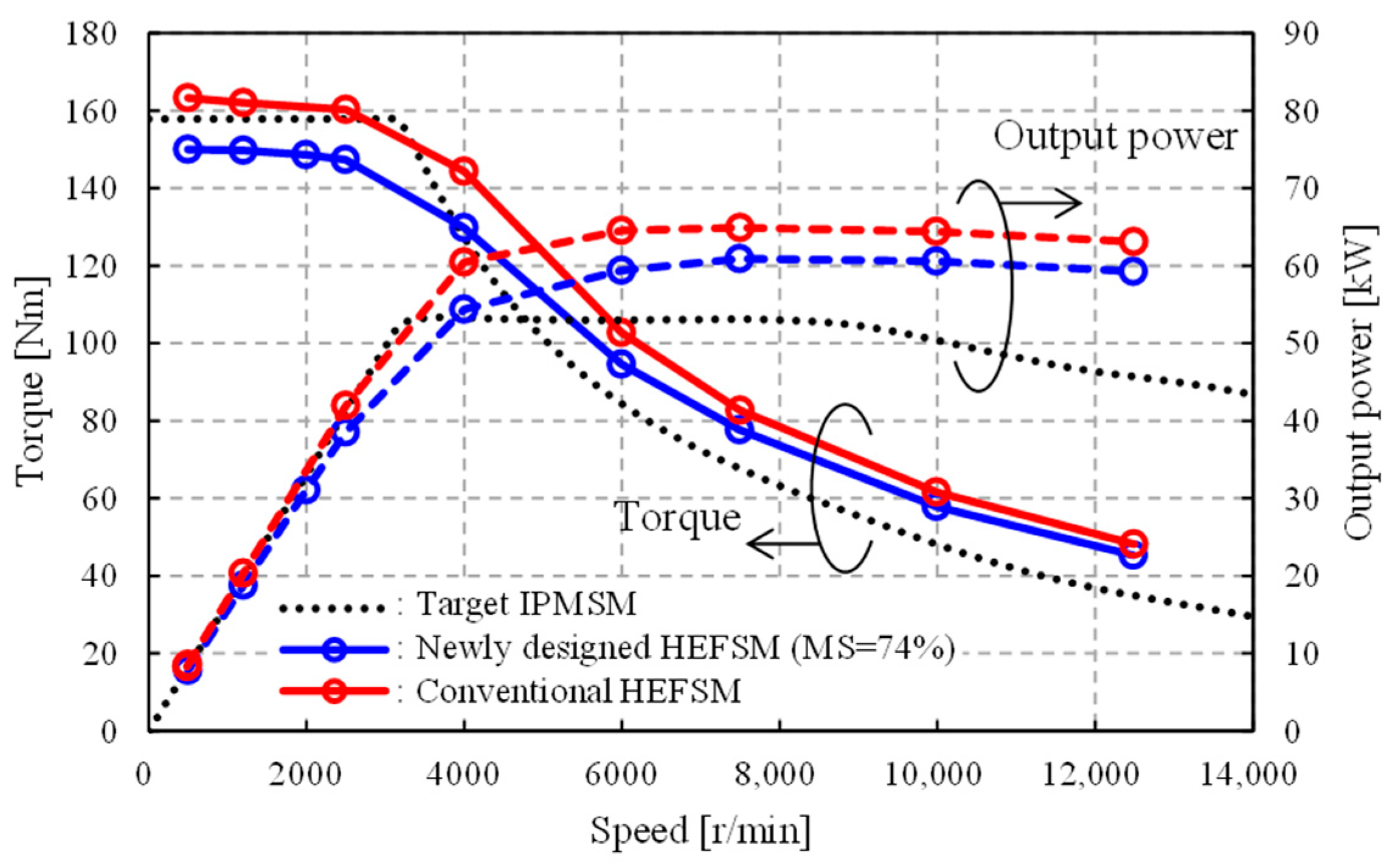
4.5. Measured Maximum Torque and Power vs. Speed Curves

Figure 14 is the maximum torque and power vs. motor speed curves measured in the newly designed HEFSM with VM-PM and the conventional HEFSM under the same electrical limitations of the maximum inverter current up to 170 Arms and the maximum DC-bus voltage up to 600 V shown in Table 1. The FEC current is also adjusted for the given operating condition within the maximum limit of 50 DCA. Similar to the measurements of the torque–armature current-FEC current characteristics, as an example, the MS of VM-PM in the newly designed HEFSM was set to +74% as its maximum. In the conventional HEFSM, the measured maximum power was 64.9 kW at 7500 r/min, well above the target value of 53 kW in Table 1, whereas, in the newly designed HEFSM, the measured maximum power was 60.4 kW at 7500 r/min, which was a little smaller than that of the conventional HEFSM. This difference was caused by the insufficient considerations on magnetic circuit design of the new HEFSM. Even so, the target requirement of 53 kW, listed in Table 1, could be successfully satisfied in the newly designed HEFSM. Although the motor speed was limited up to 12,500 r/min due to the critical speed of a bearing used, these measurements were safely conducted without any mechanical problems.

4.6. Motor Efficiency Improvement by MS Change at Low-Torque Operating Area

Table 7 and Table 8 show the 2D-FEA predicted and measured motor efficiencies and the losses at the frequent low-torque operating points No.1, 3, 5, 7, and 8, respectively, for the strengthening magnetization state with +74% and the weakened one with +28%. In both the 2D-FEA predictions and the measurements, a set of control parameters at each operating point, such as Id, Iq and If in the current vector control region and voltage phase lead angle in the six-step voltage control region, were determined so as to meet the required torque while maximizing the motor efficiency under the applied voltage limitation. In addition, the three-phase current profiles and the FEC current inputted to 2D-FEA were treated as ideal sinusoidal current profiles with no consideration of PWM harmonics and ideal DC current, respectively. Assuming that the high filling factor coils were employed, the winding resistances listed in Table 5 were used to calculate the copper losses Pca and Pcf.
As can be seen from Table 7, +74% MS contributed to high efficiency operation rather than +28% MS at the low-speed range below 2500 r/min. In contrast, +74% MS degraded the motor efficiency and +28% MS improved the motor efficiency at high-speed region beyond 10,000 r/min. Similar to the 2D-FEA predictions, it is revealed from Table 8 that the MS adjustment enabled improvement of the motor efficiency measured for the whole operating speed range. With +74% MS at the low-speed region, the back-emf coefficient, higher than that of the IPMSM shown in Figure 12a, could reduce the torque current Iq without any FEC excitation so that the motor efficiency could be improved, owing to the reductions of copper losses Pca and Pcf. However, with +28% MS at the high-speed region, the back-emf, sufficiently lower than that of the IPMSM shown in Figure 12b, could decrease the iron loss Pi resulted in the motor efficiency improvement. Compared with the motor efficiency measured in the conventional HEFSM shown in Table 2, the new HEFSM with VM-PMs measured realized higher motor efficiency at the low-speed region. However, that was a matter of course because the new HEFSM used an approximately double amount of PM. The point to be emphasized in this study is that if a CM-PM corresponding to a VM-PM with +74% MS is just replaced instead of the VM-PM, motor efficiency improvements in both the low- and the high-speed would be difficult.

5. Discussion

In Figure 12, it has been found that there was a large deviation between the 3D-FEA predicted and the measured back-emf coefficient curves. As mentioned earlier, at the design stage of new HEFSM with VM-PMs, JMAG-Designer ver. 19.0.05 was used as a FEA solver. In this version of solver, a VM-PM was modeled as a magnetically reversible linear material. The parameters possible to be dealt with in this solver were the remanences with respect to the different magnetic field intensities applied when the VM-PM was initially magnetized, and constant relative recoil permeability, regardless of the different magnetic field intensities, was applied. However, NL720MC20, used in this study as the VM-PM, was a magnetically irreversible no-linear material, as shown in Figure 4. This is a major reason why the large deviation occurred.
Fortunately, the latest JMAG Designer ver. 20.0.01, available from February 2021, could model the VM-PM as magnetically irreversible no-linear material considering, not only the remanences and variable relative recoil permeability, but also other parameters, such as coercive force, the drooping characteristic of relative recoil permeability, a square characteristic at Knick point. Additionally, all parameters could include their dependency on the different magnetic field intensities applied when the VM-PM was initially magnetized. Figure 15 illustrates the 3D-FEA predicted back-emf coefficient curve revised using the solver with latest version. As can be seen from the figures, the error is dramatically reduced. In particular, the computed MS rate after applying six times the short duty maximum FEC current density agrees well with what was measured. However, some error still remains due to no consideration of the hysteresis characteristics of the B-H curves with respect to variation of the magnetic field applied to the VM-PM during the magnetization state change in the real machine. To accurately predict the MS change rate at the design stage, correct measurement of B-H data of VM-PM and utilization of a proper FEA solver according to the measured B-H data are indispensable.

6. Conclusions

This paper presented the basic design and experimental studies on the new HEFSM, which employed a new Nd-Fe-B type magnet with high residual flux density and low coercive force as the VM-PM to improve motor efficiency. Based on the problem found in the conventional HEFSM, the design criteria from (A) to (D) for new HEFSM with the VM-PM was figured out as a traction motor for a target traction drive application. (A), (B), and (D) were confirmed by both the FEA simulations and the experimental tests and discussed. Although this paper did not deal with the design criteria (C), the magnetization durability during the high-load operation was investigated by FEA simulations and experimental tests as already reported in [17]. On the other hand, thanks to the VM-PM, the new HEFSM was able to realize variable flux capability by not only the mmf of FECs but also that of the VM-PMs by applying a quasi-impulse current to the FECs. The new HEFSM was able to not only reduce the copper loss by making continuous excitation of the FEC unnecessary thanks to strengthening the magnetization state of VM-PMs but also decrease the iron loss by properly adjusting the magnetization state of VM-PMs. In conclusion, the VM-PMs coupled with HEFSM was a promising solution for making it possible to achieve higher motor efficiency at low-torque operating points for the whole speed range. Concerning the maximum torque, the new HEFSM output 150.0 Nm under +74% MS and the short duty maximum FEC current in measurement, which was 9% down compared with the conventional HEFSM due to the reduced mmf of FECs.
As future work, another HEFSM with VM-PMs will be designed to achieve higher power density and higher motor efficiency while keeping design constraints and specifications, such as the limitations of the total amount of PM volume and three times the short duty maximum FEC current density for MS control, maximum torque, and maximum power. In addition, an ease of manufacturability, a cooling system design, and noise and vibration issues will limit application of HEFSM to the real vehicle drive, and therefore, these are also indispensable tasks as further study.

Author Contributions

Conceptualization, T.O. and T.K.; methodology, T.O. and T.K.; software, T.O. and H.M.; validation, T.O. and H.M.; formal analysis, T.O.; investigation, T.O. and T.K.; resources, T.O.; data curation, T.O.; writing—original draft preparation, T.O.; writing—review and editing, T.K. and N.M.; visualization, T.O. and T.K.; supervision, T.K.; project administration, T.K.; funding acquisition, T.K.; All authors have read and agreed to the published version of the manuscript.

Funding

This paper is based on results obtained from the future pioneering program “Development of Magnetic Material Technology for High-efficiency Motors” (JPNP14015) commissioned by the New Energy and Industrial Technology Development Organization (NEDO).

Conflicts of Interest

The authors declare no conflict of interest.

Abbreviations

NMechanical motor speed
TMotor torque
Idd-axis current
Iqq-axis current
IfField current
βCurrent lead angle
ηmMotor efficiency
PcaCopper loss in armature windings
PcfCopper loss in field excitation coils
PiIron loss
BrResidual flux density
HcBCoercive force
HcJCoercive force
HmagMagnetic field required for fully magnetizing VM-PMs
VlFundamental component of line-to-line induced voltages in three-phase armature
windings in RMS
KeBack-emf coefficient in an open circuit
Ke_0%Back-emf coefficient at the MS of 0% analyzed by 3D-FEA
Ke_100%Back-emf coefficient at the MS of 100% analyzed by 3D-FEA

References

  1. Jeong, J.; Kim, N.; Stutenberg, K.; Rousseau, A. Analysis and model validation of the toyota prius prime. SAE Tech. Pap. 2019. [Google Scholar] [CrossRef]
  2. Momen, F.; Rahman, K.; Son, Y. Electrical propulsion system design of chevrolet bolt battery electric vehicle. IEEE Trans. Ind. Appl. 2019, 55, 376–384. [Google Scholar] [CrossRef]
  3. Nonobe, Y. Development of the fuel cell vehicle mirai. IEEJ Trans. Electr. Electron. Eng. 2017, 12, 5–9. [Google Scholar] [CrossRef] [Green Version]
  4. Hoang, E.; Lecrivain, M.; Gabsi, M. A new structure of a switching flux synchronous polyphased machine with hybrid excitation. In Proceedings of the 2007 European Conference on Power Electronics and Applications, Aalborg, Denmark, 2–5 September 2007. [Google Scholar] [CrossRef] [Green Version]
  5. Hua, H.; Zhu, Z.Q.; Zhan, H. Novel consequent-pole hybrid excited machine with separated excitation stator. IEEE Trans. Ind. Electron. 2016, 63, 4718–4728. [Google Scholar] [CrossRef]
  6. Ding, W.; Li, S. Maximum ratio of torque to copper loss control for hybrid excited flux-switching machine in whole speed range. IEEE Trans. Ind. Electron. 2019, 66, 932–943. [Google Scholar] [CrossRef]
  7. Yang, H.; Lin, H.; Zhu, Z.Q. Recent advances in variable flux memory machines for traction applications: A review. CES Trans. Electr. Mach. Syst. 2018, 2, 34–50. [Google Scholar] [CrossRef]
  8. Okada, T.; Matsumori, H.; Kosaka, T.; Matsui, N. Hybrid excitation flux switching motor with permanent magnet placed at middle of field coil slots and high filling factor windings. CES Trans. Electr. Mach. Syst. 2019, 3, 248–258. [Google Scholar] [CrossRef]
  9. Okada, T.; Otsuka, K.; Matsumori, H.; Kosaka, T.; Matsui, N. Design and experimental studies on HEFSM employing two types of permanent magnet per poles as traction motor for automobile applications. In Proceedings of the 2020 23rd International Conference on Electrical Machines and Systems (ICEMS), Hamamatsu, Japan, 24–27 November 2020; pp. 521–526. [Google Scholar]
  10. Sakai, K.; Yuzawa, N.; Hashimoto, H. Permanent magnet motors capable of pole changing and three-torque -production mode using magnetization. IEEJ J. Ind. Appl. 2013, 2, 269–275. [Google Scholar] [CrossRef] [Green Version]
  11. Hua, H.; Zhu, Z.Q.; Pride, A.; Deodhar, R.; Sasaki, T. Comparative study of variable flux memory machines with parallel and series hybrid magnets. IEEE Trans. Ind. Appl. 2018, 52, 1408–1419. [Google Scholar] [CrossRef]
  12. Yang, H.; Zhu, Z.Q.; Lin, H.; Wu, D.; Hua, H.; Fang, S.; Huang, Y. Novel high-performance switched flux hybrid magnet memory machines with reduced rare-earth magnets. IEEE Trans. Ind. Appl. 2016, 52, 3901–3915. [Google Scholar] [CrossRef]
  13. Yang, H.; Lin, H.; Zhu, Z.Q.; Wang, D.; Fang, S.; Huang, Y. A variable-flux hybrid-pm switched-flux memory machine for EV/HEV applications. IEEE Trans. Ind. Appl. 2016, 55, 2203–2214. [Google Scholar] [CrossRef]
  14. Maeda, Y.; Kosaka, T.; Matsui, N. Design study on hybrid excitation flux switching motor with permanent magnet placed at middle of field coil slot for hev drives. In Proceedings of the 2016 XXII International Conference on Electrical Machine (ICEM), Lausanne, Switzerland, 4–7 September 2016; pp. 2524–2530. [Google Scholar] [CrossRef]
  15. Mizutani, R.; Haruno, K.; Mizutani, T. Technical trend of electric drive assisted system for automobile i –development of new motor of compact class hybrid electric vehicles in TOYOTA. In Proceedings of the 2017 IEE-Japan Industry Applications Society Conference, Hokkaido, Japan, 29–31 October 2017. [Google Scholar]
  16. Fukushige, T.; Limsuwan, N.; Kato, T.; Akatsu, K.; Lorenz, R.D. Efficiency contours and loss minimization over a driving cycle of a variable flux-intensifying machine. IEEE Trans. Ind. Appl. 2015, 51, 2984–2989. [Google Scholar] [CrossRef]
  17. Otsuka, K.; Okada, T.; Mifune, T.; Matsumori, H.; Kosaka, T.; Matsui, N. Basic study on efficiency improvement of hybrid excitation flux switching motor using variably magnetizable permanent magnets for automotive traction drives. In Proceedings of the 2020 IEEE Energy Conversion Congress and Exposition (ECCE), Detroit, MI, USA, 11–15 October 2020; pp. 27–34. [Google Scholar] [CrossRef]
Figure 1. Sectional view of the conventional HEFSM. CM-PM, constantly magnetized-permanent magnets; FEC, field excitation coil. ©2020 IEEE. Reprinted with permission, from K. Otsuka, T. Okada, T. Mifune, H. Matsumori, T. Kosaka and N. Matsui, Proceeding of 2020 IEEE Energy Conversion Congress and Exposition (ECCE), IEEE, 2020.
Wevj 12 00058 g001
Figure 2. Field flux paths of the conventional HEFSM. (a) under no FEC excitation; (b) under FEC excitation.
Wevj 12 00058 g002
Figure 3. Schematic diagram of B-H curves of CM- and variably magnetizable-permanent magnets (VM-PM), and magnetization manipulation of VM-PM. ©2020 IEEE. Reprinted with permission, from K. Otsuka, T. Okada, T. Mifune, H. Matsumori, T. Kosaka and N. Matsui, Proceeding of 2020 IEEE Energy Conversion Congress and Exposition (ECCE), IEEE, 2020.
Wevj 12 00058 g003
Figure 4. Measured B-H curves of NL720MC20.
Wevj 12 00058 g004
Figure 5. Detailed specifications of design criteria.
Wevj 12 00058 g005
Figure 6. Comparison of stator major parts between the conventional and the new hybrid excitation flux switching motors (HEFSM). (a) conventional HEFSM; (b) newly designed HEFSM with VM-PM. ©2020 IEEE. Reprinted with permission, from K. Otsuka, T. Okada, T. Mifune, H. Matsumori, T. Kosaka and N. Matsui, Proceeding of 2020 IEEE Energy Conversion Congress and Exposition (ECCE), IEEE, 2020.
Wevj 12 00058 g006
Figure 7. Flux paths of the newly designed HEFSM with VM-PM. (a) under no FEC excitation and strengthened magnetization state of VM-PM; (b) under no FEC excitation and weakened magnetization state of VM-PM; (c) under FEC excitation and strengthened magnetization state of VM-PM. ©2020 IEEE. Reprinted with permission, from K. Otsuka, T. Okada, T. Mifune, H. Matsumori, T. Kosaka and N. Matsui, Proceeding of 2020 IEEE Energy Conversion Congress and Exposition (ECCE), IEEE, 2020.
Wevj 12 00058 g007
Figure 8. Photographs of fabricated new HEFSM. (a) enlarged view of stator (CM-PM); (b) enlarged view of stator (VM-PM); (c) whole stator assembly; (d) whole rotor assembly. ©2020 IEEE. Reprinted with permission, from K. Otsuka, T. Okada, T. Mifune, H. Matsumori, T. Kosaka and N. Matsui, Proceeding of 2020 IEEE Energy Conversion Congress and Exposition (ECCE), IEEE, 2020.
Wevj 12 00058 g008
Figure 9. Experimental setup for efficiency measurement under normal operation. ©2020 IEEE. Reprinted with permission, from K. Otsuka, T. Okada, T. Mifune, H. Matsumori, T. Kosaka and N. Matsui, Proceeding of 2020 IEEE Energy Conversion Congress and Exposition (ECCE), IEEE, 2020.
Wevj 12 00058 g009
Figure 10. Experimental setup for changing the magnetization state of VM-PMs.
Wevj 12 00058 g010
Figure 12. Measured and 3D-FEA predicted back-emf coefficient curves. (a) MS strengthening region; (b) MS weakening region.
Wevj 12 00058 g012
Figure 13. Measured torque–armature current-FEC current characteristics. (a) newly designed HEFSM with VM-PM; (b) conventional HEFSM.
Wevj 12 00058 g013
Figure 14. Measured maximum torque and power vs. speed curves.
Wevj 12 00058 g014
Figure 15. Measured back-emf coefficient curves and 3D-FEA predicted using JMAG-Designer ver. 20.0.01.
Wevj 12 00058 g015
Table 1. Design constraints and target performances. ©2020 IEEE. Reprinted with permission, from K. Otsuka, T. Okada, T. Mifune, H. Matsumori, T. Kosaka and N. Matsui, Proceeding of 2020 IEEE Energy Conversion Congress and Exposition (ECCE), IEEE, 2020.
ItemsIPMSMHEFSM
Stator outer diameter [mm]215215
Motor axial length [mm]117.5<117.5
Air gap length [mm]0.80.8
CM-PMs weight [kg]0.54<0.55
Max. DC-bus voltage inverter [V]600600
Withstand voltage of switching device [V0-p]12001200
Max. inverter current [Arms]170170
Max. current density in armature windings [Arms/mm2]2626
Max. current density in FECs [A/mm2]NA26
Maximum torque [N·m]163>163
Maximum output power [kW]53>53
Maximum speed [r/min]17,00017,000
Table 2. 3D-FEA predicted and measured efficiency and loss analysis of the conventional HEFSM at frequent operating points.
Frequent Operating Points3D-FEA PredictedMeasured
No.N
[r/min]
T
[N·m]
ηm
[%]
Pca
[W]
Pcf
[W]
Pi
[W]
ηm
[%]
Pca
[W]
Pcf
[W]
Pi
[W]
112001087.689742283.51186982
212006085.15736688881.9657720339
325001092.396745886.612575220
4250010089.71331139432185.5123321471097
540001093.8967411887.185131391
675001094.79610125287.782295714
710,0001094.710410139087.0893501121
812,5001094.610413251786.61244021669
Table 3. Optimum current combinations Id-Iq-If for the given operating points under the 3D-FEA prediction and the measurements.
Frequent Operating Points3D-FEA PredictionsMeasurements
No.N
[r/min]
T
[N·m]
Id
[A]
Iq
[A]
If
[A]
Id
[A]
Iq
[A]
If
[A]
112001044165486
2120060610618−811319.5
3250010−4436−12486
42500100−1416026−4314932.5
5400010−4436−15388
6750010−18407−342112
710,00010−20407−352213
812,50010−26368−451914
Table 4. Comparison of two types of VM-PM arrangements.
ItemsVM-PM Inner ArrangementVM-PM Outer Arrangement
Stator main part
Wevj 12 00058 i001
Wevj 12 00058 i002 Wevj 12 00058 i003
Maximum torque capabilityGoodFair
Demagnetization durability of VM-PMLowHigh
Coercive force Hcj required for VM-PM to avoid demagnetization during high-load operationHighLow
Quasi-impulse FEC current density required for changing the magnetization state of VM-PMHighLow
Table 5. Specifications of designed new HEFSM with VM-PMs. ©2020 IEEE. Reprinted with permission, from K. Otsuka, T. Okada, T. Mifune, H. Matsumori, T. Kosaka and N. Matsui, Proceeding of 2020 IEEE Energy Conversion Congress and Exposition (ECCE), IEEE, 2020.
ItemsConventionalNewly Designed
Major dimensions and specificationsStator outer diameter [mm]215
Motor total axial length [mm]129128
Motor core stack length [mm]70
Rotor outer diameter [mm]154.8
Air gap length [mm]0.8
Type of electromagnetic steel30JNE1500
Armature winding’s specificationsNo. of turns/coil12
Type of connection3Φ-Y
Filling factor *0.7 *
Maximum current density * [Arms/mm2]26.0 *
Resist/phase * [mΩ] at 100 °C51.3 *49.2 *
FEC specificationsNo. of turns/coil5039
Filling factor *0.7 *
Maximum current density * [A/mm2]26.0 *
Maximum ampere-turns per slot [AT]50003900
Resist * (12 coils connected inseries) [Ω] at 100 °C2.06 *1.46 *
CM-PM specificationsType of permanent magnet (outside)N52TS-SGF
Type of permanent magnet (inside)N44TU-GR
CM-PMs weight [g]549.8
VM-PM specificationsType of permanent magnetNANL720MC20
Size (W × H × L [mm])NA6.0 × 12.0 × 70
VM-PMs weight [g]NA456.5
* These are the values expected at the design stage when high filling factor windings using flat shape rectangular wires are employed for the armature windings and the FECs.
Table 6. Specifications of armature windings and FECs in the fabricated conventional and new HEFSMs.
ItemsConventionalNewly Designed
Armature winding’s specificationsFilling factor0.54
Maximum current density [Arms/mm2]33.8
Resist/phase [mΩ] at 100 °C66.764.0
FEC’s specificationsFilling factor0.55
Maximum current density [DCA/mm2]33.233.3
Resist (12 coils connected inseries) [Ω] at 100 °C2.611.87
Table 7. 2D-FEA predicted motor efficiency and loss analysis results.
Frequent Low-Torque Operating Points2D-FEA Predicted Motor Efficiency and Loss Analysis of
Newly Designed HEFSM with VM-PMs
+74% Magnetization State of VM-PM+28% Magnetization State of VM-PM
No.N [r/min]T [Nm]ηm
[%]
Pca
[W]
Pcf
[W]
Pi
[W]
ηm
[%]
Pca
[W]
Pcf
[W]
Pi
[W]
112001096.13301994.559014
325001096.83805096.459238
540001096.94309696.965268
710,0001096.7116025297.11080210
812,5001096.6116036097.01240283
Table 8. Measured motor efficiency and loss analysis results.
Frequent Low-Torque Operating PointsMeasured Motor Efficiency and Loss Analysis of
Newly Designed and Fabricated HEFSM with VM-PMs
+74% Magnetization State of VM-PM+28% Magnetization State of VM-PM
No.N [r/min]T [Nm]ηm
[%]
Pca
[W]
Pcf
[W]
Pi
[W]
ηm
[%]
Pca
[W]
Pcf
[W]
Pi
[W]
112001092.64705490.770055
325001093.346514292.46922130
540001093.475024093.07523234
710,0001091.181099291.48957888
812,5001091.110513124692.48995974
Publisher’s Note: MDPI stays neutral with regard to jurisdictional claims in published maps and institutional affiliations.

