Article

Heat Transfer Enhancement of Liquid Cooled Copper Plate with Oblique Fins for Electric Vehicles Battery Thermal Management

Department of Mechanical and Manufacturing Engineering, Universiti Kebangsaan Malaysia, Bangi 43600, Selangor, Malaysia
*
Authors to whom correspondence should be addressed.
World Electr. Veh. J. 2021, 12(2), 55; https://doi.org/10.3390/wevj12020055
Submission received: 22 February 2021 / Revised: 23 March 2021 / Accepted: 30 March 2021 / Published: 1 April 2021

Abstract

:
As the automotive industry progresses, electric vehicles (EV) grow with increasing demand throughout the world. Nickel-metal hydride (NiMH) battery and lithium-ion (Li-ion) are widely used in EV due to their advantages such as impressive energy density, good power density, and low self-discharge. However, the batteries must be operated within their optimum range for safety and good thermal management to enable a longer lifespan, lower costs, and improve safety for EV batteries. The need for a liquid cold plate (LCP) to be used in EV batteries is now highly reliable on the distribution of the required temperature rather than only standard cooling systems. The fins arrangement in the LCP would likewise impact the cooling efficiency of the EV battery. The main objective of this paper is to determine the heat transfer enhancement of liquid cold plate systems with the oblique fin and different types of liquid coolants. In the experimental test, two liquid types are used namely G13 ethylene glycol and distilled water in five steps, 10% ethylene glycol, 100% distilled water, 75% ethylene glycol + 25% distilled water, 50% ethylene glycol + 50% distilled water, and 25% ethylene glycol + 75% distilled water. Three different flow rates have been utilized which are 0.3, 0.5, and 0.7 GPM to maximize the productivity of flowing fluid and heat transferring with the gate door valve. The LCP encompasses the inline configuration of the oblique fin, which is able to enhance the heat transfer rate from the heater to the liquid cold plate. A GPM of 0.7 reached the least surface temperature for the battery in the three different flow levels. The LCP is capable of sustaining the ambient surface temperatures of the batteries just under the permissible 50 °C operating temperature, which indicates that the developed LCP with the oblique fin may perhaps become an effective option for the thermal control of EV batteries.

1. Introduction

The auto industry has advanced towards vehicles sustainability, comprising of electric vehicles (EV) and hybrid electric vehicles (HEV), amid rising concern about environmental considerations. The greater use of EV will help reduce the carbon footprint and limit the increment of the average global temperature to 1.5 °C by 2050, as targeted by the International Energy Agency (IEA). Batteries have a critical part to play within the development of electric vehicles. The market for batteries made from lithium-ion (Li-ion) throughout the EV productions have increased over the years. Batteries made up of Li-ion offer substantial pluses, for example, the energy output is high, and the level of low self-discharges as well as the extended life cycles are relative to many other batteries [1]. Thermal problems with the Li-ion batteries, however, have been a downside to these batteries. Li-ion batteries are temperature sensitive. The battery’s life cycle, performance, reliability, and safety are affected by the temperature [2]. Given the sensitivity of the temperature, a lot of heat energy is emitted during the charge/discharge process. Moreover, a large amount of heat is generated due to the electrochemical reactions and resistance, which will trigger the battery to spike in temperature. The thermal runaway would appear in the Li-ion battery pack cell when the heat of the battery pack is dramatically increased. Various cooling techniques are available to sustain the batteries made from Li-ion at optimal temperatures, including the phase change material (PCM), air cooling, and liquid cooling. The air cooling structure was engineered by Xie et al. [3] through utilizing the orthogonal design system. It was discovered that the highest temperature and temperature differences were decreased to 12.82 and 29.72%, respectively with the optimization process. Xu and He published a study on the performance of the heat dispersion of a battery pack utilizing forced air cooling [4]. The horizontal battery pack has indeed been reported to have a greater thermal performance than the horizontal battery pack. In comparison with the traditional air cooling system as well as the passive cooling process, Kizilel et al. [5] utilized the PCM. It has been observed that the passive cooling system by means of PCM prevents a heat spread. Numeric and experimental studies of the functionalities of the transfer of heat and the flow of fluid transfer of air cooled by the oblique finning heating basin have been conducted by Kanargi et al. [6].
The secondary fluctuations caused by the oblique canals of the oblique-finned heat sink appropriately interfered, reinitiating the boundary layers of oblique fins in three walls and reducing thermal resistance over the entire spectrum of air flow rates. This same pack temperature from the Li-ion battery could be effectively handled at a temperature range between 20 to 55 °C [1]. Even so, the heat locally generated will rise rapidly due to a higher power drain, higher ambient temperature or higher energy charging. As a result, additional temperatures may be created in the battery pack modules and there could be thermal runaway. To keep the battery temperature secure, a credible system of thermal management is imperative. This device can also offer a stable operating temperature for the battery without restricting the output of the battery. The liquid cooling system is an outstanding high energy density cooling process for the battery. Even so, the system’s price and difficulty have been shown to be a limitation of the system. The methods of liquid refrigeration can be categorized as cooling indirectly and cooling directly. Cooling directly involves a close contact between the liquid and battery, whereas cooling indirectly involves pumping the tubes all over the battery. Rather than conducting direct cooling, it is simpler to perform indirect cooling with covers. Due to its low viscosity, the glycol solution is regarded as the most efficient coolant for the indirect cooling system. Particularly in comparison to the use of coolant made up of dielectric mineral oil, the pumping strength is not controlled by the glycol solution and possesses a high amount of heat prospects for the fluctuations of temperature in the system. Since the glycol solution will achieve stability, the thermal conductivity is higher in comparison to oil [1]. An et al. [7] experimentally studied the cooling process on the prismatic battery pack using a flow boiling mini-channel cold plate. They investigated the cooling effect on the temperature and voltage distribution. Their findings showed that the battery temperature was sustained in the range of 40 °C and the temperature difference of the battery cell was maintained within 4 °C. In terms of voltage distribution, they found that the voltage of the battery cell dropped with the increase in the flow rate due to the temperature drop. On the other hand, at a higher discharge rate, the uniformity of the temperature and voltage distribution tended to decrease. Feng et al. [8] showed the details mechanism of reaction during the thermal runaway for the Li-ion battery. According to Li and Zou [9], both the water and glycol have a high thermal conductivity but the shortage of the water is due to boiling at a high temperature, while the temperature range is wider for glycol. However, the temperature consistency of the battery module can be accomplished. The use of nanofluids and coolant was investigated at different test parameters to enhance the performance of the system [10,11,12,13]. Azmi Roslan et al. [14] investigated the effect of mixing water and ethylene glycol with different ratios of 10:90, 20:80, 30:70, 40:60, 50:50, 60:40, 70:30, 80:20, and 90:10. The obtained results showed that 40% of ethylene glycol and 60% of water are the best properties for a coolant to be used. Panchal [15] built an apparatus that used double cold plates with separate charging/discharging periods for Li-ion pouch cells with an indirect liquid cooling technique. The unit has been built to evaluate the distribution of surface temperature, the fluctuation of heat, and battery temperature rise. The results showed that the degree of discharge and the maximum conditions influenced the heat generation rates considerably. Zhao et al. [16] suggested an ideal high and local temperature range for the mini-channel cylinder for liquid cooling. The effect of the channel quantity, the rate of mass flow, the flow direction, and input size were determined by adjusting the thermal dissipation efficiency. The results indicated that with the rate of mass flow for injections of 1–10−3 kg/s and the number of mini-channels constrained to four, temperatures can be regulated below 40 °C. In addition, it was identified that in comparison to the free convection cooling, this type of cooling provides better conditions. A simulated experimental analysis was performed by Panchal et al. [17] in a mini-channel cold plate for big prismatic lithium-ion batteries cooled by water. Two different release frequencies were conducted in the study, 1 and 2 °C, as well as separate operating temperatures of coolants, 5, 15, and 25 °C. It was discovered that as the discharge rates rise, the distribution of temperature inside the mini-channel cold plates increase.
Huo et al. [18] developed an EV battery heat management device on the basis of liquid cooled mini-channel plate. The influence of the flow path, the inlet weight, the number of channel, as well as ambient temperatures were explored via the development of a 3D model. The greater the channel numbers and the mass flow rate, the smaller the battery temperatures. The findings show that the flow path has a slight impact on the cooling efficiency after the mass flow rate rises. Even so, the pattern of growth will decrease as the rate of flow increases since an acceptable rate of flow is selected. The findings of the simulation also show that the cooling system cannot avoid the thermal rank incidence in the battery cell if the rate of the mass flow reached up to 10 LPM. A study on thermal battery pack control using the liquid cooling method was carried out by Karimi and Dehghan [19]. The inlets and outlets vary from these two setups in two modelled environments, configuration U and configuration Z. By determining the standard deviations, the distribution of the temperatures inside the EV battery is determined. The findings reveal that the Z-configurations for the liquid cooling system demonstrate greater temperature uniformity. Experiments on liquid cooled plates containing oblique mini-channels were performed by Jin et al. [20]. It was summarized that the heat transfer coefficient by the oblique mini-channel is greater than the straight mini-channel. For 1240 W, the LCP will retain the battery temperature below 50 °C at a coolant flow rate which is less than 0.9 LPM. The convective heat flow in the axial direction decreased progressively by direct mini-channels at the peak temperature and the temperature gradient of the investigation was performed by Lee et al. [21].
This situation is induced due to the thickness increase along the thermal boundary layer flow path. The arrangements of the oblique fin can be used to shape smaller branching channels. This process will enhance the heat transfer rate through the mini-channel. Prajapati et al. [22] undertook an analysis to compare the efficacy of three micro-channels, which contain the same cross-section, divergent cross-section, and obliquely finned micro-channel. The oblique micro-channel revealed the maximum thermal transfer coefficient from the sample. Wang et al. [23] concluded that a high range of heat transfer efficiency would rise when the oblique fin was inclined. Li et al. [24] investigated the thermal performance using the silicon cold plate for the battery thermal management system. They combined the application of copper tubes and silicon cold plates. The results showed that this combination of copper tubes and silicon cold plates is able to transfer and absorb the heat through the water flowing inside the copper tubes and the temperature decreases to 1.78 C at 8 mL/s of volume flow rate. Furthermore, the copper tubes energy consumption deteriorated by 47.4%. Lee et al. [25] observed in many other situations that the angle of the oblique fin in the micro-channel would seriously affect the distribution of the heat and the capacity of the pressure drop. Variations in angles of the oblique fin were measured to examine their impact on the transfer of heat as well as the pressure. An increase in the oblique angles results in an increase in the performance of the micro-channel heat transfer. The existing fluids flow and the transfer of the heat project’s effectiveness is carried out in the oblique fin liquid cold plate (LCP).
The current work is carried out on oblique fins with a new type of liquid coolant namely the G13 ethylene glycol. The oblique fins structures within the LCP were observed to be inline. The influence of structures and three distinct flow rates have been experimentally explored. In both cases, ethylene glycol and distilled water are utilized as the coolant. The utilization of oblique fins and the G13 coolant to improve the system’s rate of heat transfer has not been studied before. The results of the current experiment showed that 75% of distilled water mixed with 25% of G13 ethylene glycol at the 0.7 GPM flow rate is the right parameter to operate the cold plate.

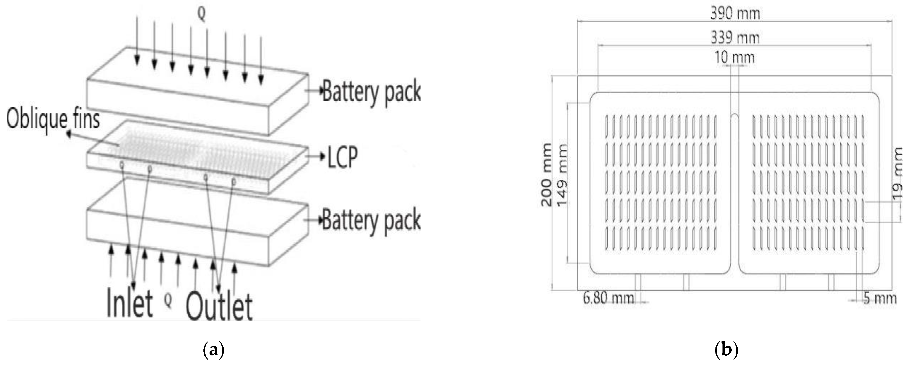
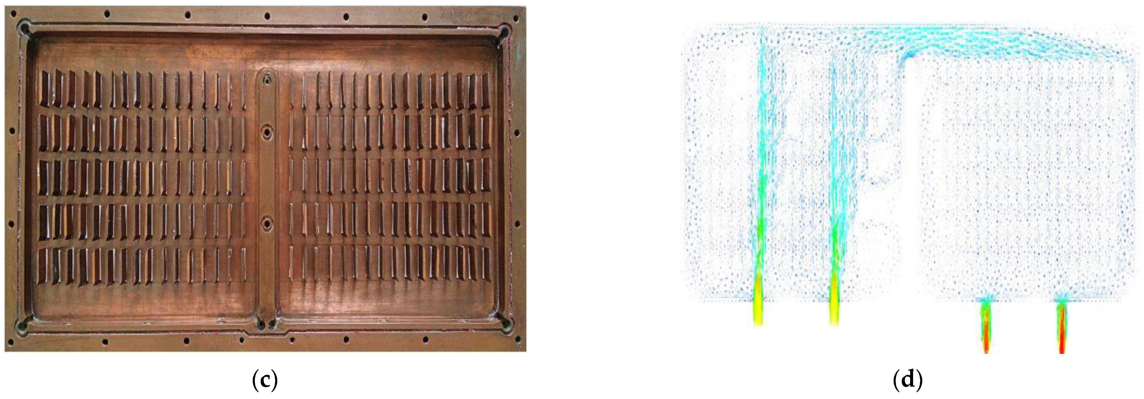
2. Design of Heater Block and Liquid Cold Plate

Usually, the battery served as a kit. Figure 1a reveals the battery’s liquid cold plate system based on a wide perspective. The LCP is placed between the upper and lower parts of battery packages. Copper is used to build the liquid cold plate and aluminum on the battery pack. The battery pack is 180 mm broad and 360 mm long, with its rectangular shape. The pack has a thickness of 32 mm, while the LCP has a diameter of 16 mm. In the LCP, there are two coolant entrance and exit channels. The LCP consists of two major parts, the upper and lower plates. The upper plate is supposed to cover the plate below, whereas the plate at the lower end serves as the art of the oblique fin that comprises a separate structure. There is a divider in the middle from the inside of the LCP and all the corners are built to be rounded to minimize the pressure loss. Using this LCP, the inline oblique fin arrangement is assessed to prove the enhancement of the flow of the fluid and transfer of heat in the battery pack. Figure 1b shows the detail dimensions for LCP and oblique fin, and Figure 1c illustrates the LCP with an oblique fin arrangement. Finally, Figure 1d shows the direction of the fluid flow.

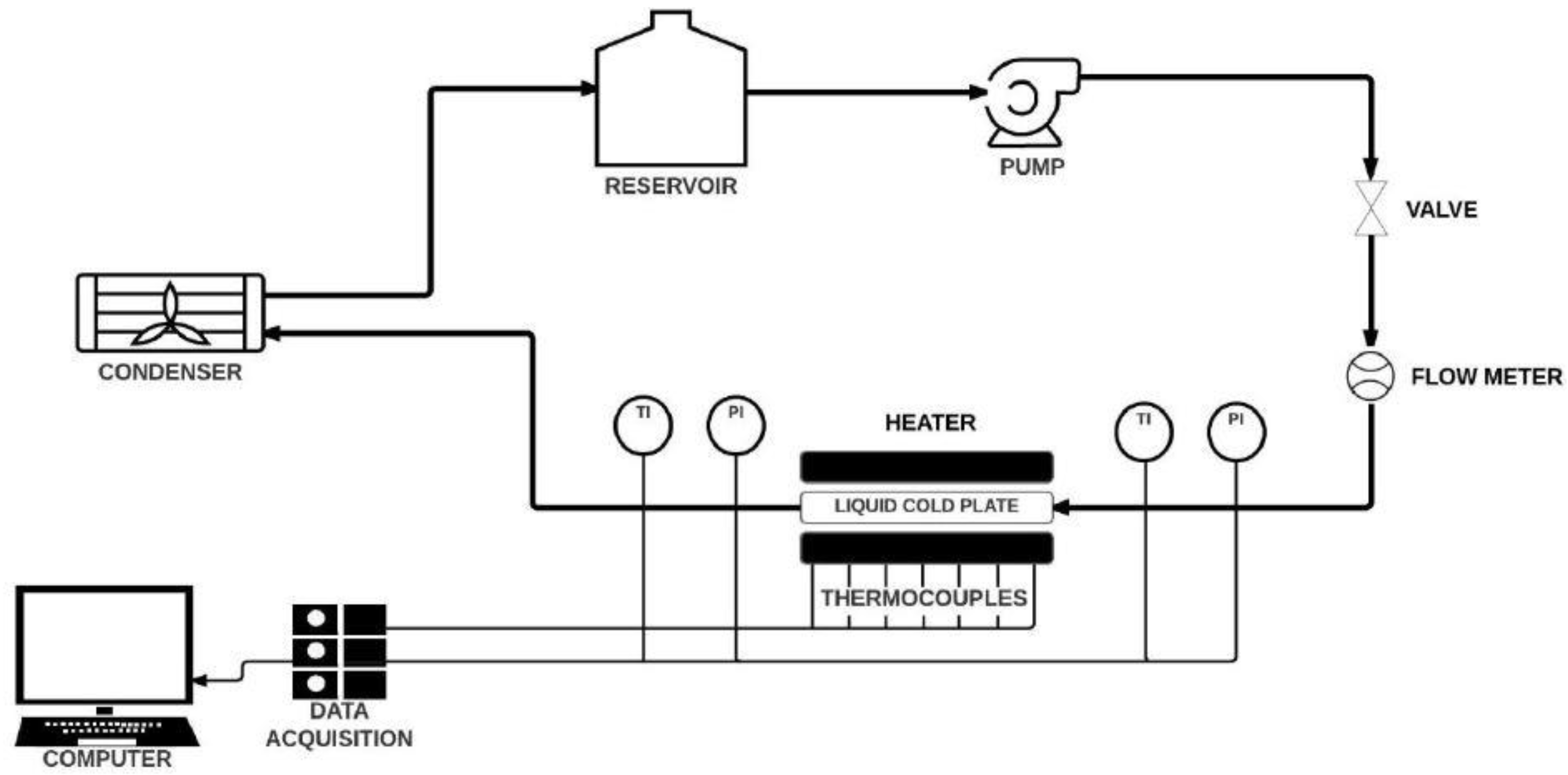
3. Experimental Setup

Figure 2 illustrates the depiction of the experiment configuration. It contains a testing section, flow meter, compressor, condenser, and reservoir (volume: 4 L). The coolants are channeled via a water pump system (Eik Seng Machinery, Lorong Sungai Nyior Indah, Penang, Malaysia). designed by Petrolla with a flow rate capacity up to 0.2 GPM. Installation of a flow meter (LZM15 G, ZYIA instrument, Zhejiang, China) is done to calculate the coolant flow rate. For controlling the coolant flow, gate valves are placed in front of the flow meter. To form K (MI), thermocouples via a complete variability of ±0.5 °C and a pressure transducer (DG-10, WIKA Instrumentation, Shah Alam, Selangor, Malaysia) are placed in the funnel prior and after the coolant flows via the test segment to establish the original and final temperatures of the coolant. Once the test component has drained out, the hot coolant can flow into the condenser (Seidon 240, Cooler Master Technology, New Taipei City, Taiwan), for its cooling prior to joining the tank. For controlling the heating block’s power, the study used two regulators of voltage (EOT 2 kW, Shanghai Xiujiang Electrical Equipment Manufacturing, Shanghai, China). In the test part, there are two key elements which are two heater blocks that work similar to the battery pack as well as the LCP. The two heater blocks are made up of aluminum to ensure the uniformity of the heat flux and contain a 1.8 kW heater sheet. To calculate the heater block surface temperature, the thermocouples of the 8 K type are connected to the heater block surface. To each of the thermocouples, the DaqPRO 5300 system (Fourtec-Fourier Technologies, Pennant Hills, New South Wales, Australia) of data acquisition is related. To allow a uniformed flow inside the LCP, two inlet and outlet channels are built. Both surfaces of the LCP were smeared by the extremely conductive thermal grease (TG-2) to decrease the thermal resistivity in the test section.

The Experimental Procedure

The switch of the heater block power is turned on and adjusted following the test segment, which is assembled and firmly sealed to reach the intended block temperature of 100 °C. Then, there is a certain wait-time to ensure that the temperature is stable. After that, the switches of the condenser and pump are turned on, while the desirable flow rate is regulated utilizing the gate valve to initiate data recording. Following the repeat of the steps with different flow rates and liquids, the system is turned off for about 40 min to cool down the temperature of the heater block.

4. Results and Discussion

The results have been classified into two parts. The first part is investigated and compared to the surface temperature with different liquid coolants at a constant flow rate, while the second part is investigated and compared to the surface temperature at a constant liquid coolant with different flow rates. The results obtained from the thermocouples are attached to the surface in the upper and lower parts of the heater block to measure the local temperature of the heater surface and are connected to the DaqPRO 5300 data acquisition system, the upper and lower parts of heater act as the batteries pack. However, the figures are provided to illustrate the local temperature of the heater surface with the inline oblique fins arrangement and different liquids, which are distilled water, ethylene glycol, and different flow rates of 0.3, 0.5, and 0.7 GPM with more details in the discussion.

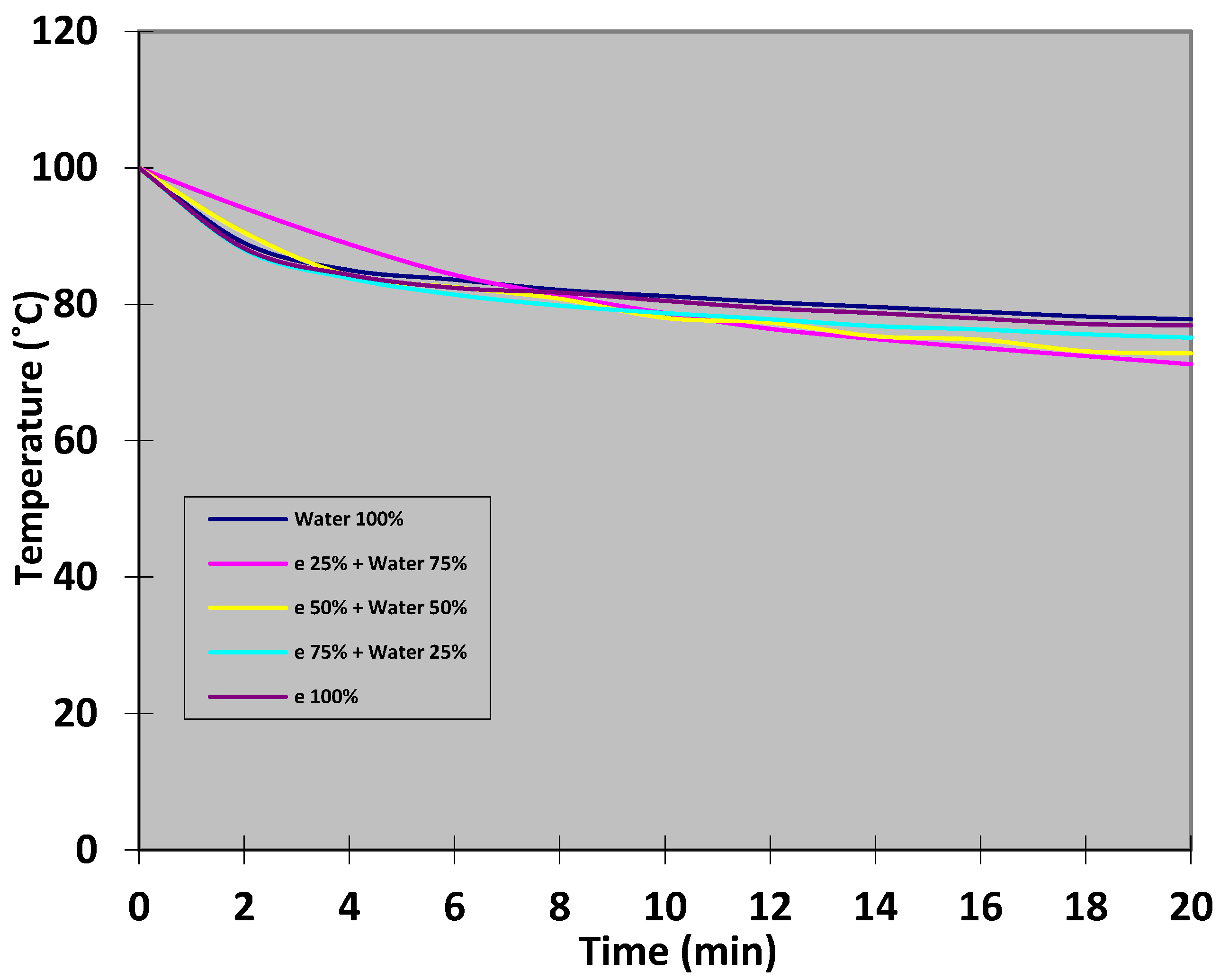
4.1. Different Liquid Coolants at a Constant Flow Rate

Figure 3 illustrates the transient response of the heater block and liquid cold plate with different percentages of distilled water and ethylene glycol at a constant flow rate of 0.3 GPM. The surface temperature increased from 26 to 100 °C after switching on the heater. At this time, the cooled liquid system was not working. However, once the surface temperature reached 100 °C, the cooled liquid system was switched on to decrease the temperature of the heater block. In the first case, 100% of distilled water was used. In the first 4 min, the temperature dropped to 85 °C until it reached 77.8 °C within 20 min. In the second case, 25% of ethylene glycol and 75% of distilled water were tested to know which of the mixed percentages were able to make the temperature under a safety range with the same flow rate of 0.3 GPM. As the graph clearly shows, the temperature reduced from the initial degree of 100 to 88.8 °C and then continued to drop to 71.2 °C within 20 min. Fifty percent of ethylene glycol and 50% of distilled water were tested in the third case. The behavior of the graph shows that the temperature dropped to 84.2 °C and continued to decrease until it reached 72.8 °C. In the fourth case, 75% of ethylene glycol and 25% of distilled water were mixed with the same flow rate at 0.3 GPM. Within 4 min, the temperature dropped to 83.8 °C until it reached 75.1 °C during 20 min. In the fifth case, 100% of ethylene glycol was used. Here, the temperature has been reduced from 100 to 84.3 °C within 4 min, during the extra time of 20 min the temperature reached 76.9 °C. By comparing the first and fifth case, 100% of distilled water was better than 100% of ethylene glycol, in which the first case was able to reduce the surface temperature to 76.9 °C within 20 min, while the fifth case was able to reduce the temperature to 77.8 °C within 20 min. This is due to the fact that the boiling point of distilled water is less than the boiling point of ethylene glycol. The results showed that the ethylene glycol and distilled water mix had the ability to decrease the temperature by more than 100% of ethylene glycol and 100% of distilled water, which led this experiment to investigate more on the mixing of both liquids with different flow rates. From the first to the fifth case, it can be seen that the lower temperature was achieved in the fifth case, which is 25% of ethylene glycol and 75% of distilled water and the temperature reached 71.2 °C within 20 min at a constant flow rate of 0.3 GPM.
Figure 4 shows the transient response of the heater block and the liquid cold plate at the 0.5 GPM flow rate. For this test, all the parameters were fixed expect for the flow rate, which was increased to 0.5 GPM. This points that by increasing the flow rate, the heat in the battery can be controlled. In the first case, 100% of distilled water was tested with the 0.5 GPM flow rate. As the graph shows, after running the system the heat surface temperature dropped to 85.2 °C within 4 min to cool it down, then during an additional time of 20 min, the temperature reached 75.8 °C. Compared with the previous test at the 0.3 GPM flow rate, the results showed that the temperature reached 75.8 °C at the 0.5 GPM flow rate within 20 min, while at the 0.3 GPM flow rate the temperature reached 77.8 °C. This means that the 0.5 GPM is higher in the performance of the heat transfer. In the second case, 25% of ethylene glycol and 75% of distilled water were mixed and used. The previous results at the 0.3 GPM flow rate showed that 25% of ethylene glycol and 75% of distilled water had a lower surface temperature. Moreover, at the 0.5 GPM flow rate, this test has a lower surface temperature. In addition, 25% of ethylene glycol and 75% of distilled water at the 0.5 GPM flow rate reduced more temperature compared to the previous case at 0.3 GPM. As the graph shows, in the first 4 min the temperature dropped to 76.5 °C and during the extra period of 20 min reached 66.1 °C. Moreover, in the third case with 50% of ethylene glycol and 50% of distilled water the temperature reduced to 79.5 °C within 4 min and reached 68.2 °C after 20 min have passed. For the fourth case, 75% of ethylene glycol and 25% of distilled water were mixed at the same flow rate of 0.5 GPM. During 4 min, the system was switched on and the temperature dropped to 85.2 °C until it reached 85.2 °C within 20 min. In the fifth case, 100% of ethylene glycol was used. At the first 4 min, the temperature was reduced from the initial degree of 100 to 81.4 °C and after 20 min reached 71.9 °C, which is lower in the temperature degree than the previous case at 0.3 GPM. Moreover, the temperature was still lower than the 100% of distilled water in both flow rates of 0.3 and 0.5 GPM.
Figure 5 shows the transient response of the heater block and the liquid cold plate using the same procedure as in the previous case, but with an increase of 0.7 GPM to keep the temperature operating within a safety range. Not only the flow rate and the liquids chosen were able to maintain the temperature under a safety range. The oblique fins played an important role in enhancing the performance of the heat transfer (Law and Lee [26]). In the first case, 100% of distilled water was used with the 0.7 GPM flow rate. In the first 4 min, the temperature dropped to 87.2 °C and during the extra time of 20 min reached 69.2 °C. The results of 100% of distilled water at 0.7 GPM showed that the temperature was lower than the previous cases when 100% of distilled was tested with 0.3 and 0.5 GPM. However, the temperature was still higher than with 100% of ethylene glycol. Twenty five percent of ethylene glycol and 75% of distilled water were mixed and used in the second case, which had a lower temperature than the previous cases. As the graph shows, in the first 4 min the temperature reached 83.4 °C and during the extra time of 20 min reached 48.5 °C. In third case with 50% of ethylene glycol and 50% of distilled water tested at the 0.7 GPM flow rate, the temperature reduced from 100 to 80.2 °C within 4 min and kept reducing until it reached 51.9 °C after 20 min. For the fourth case with 75% ethylene glycol and 25% distilled water, the results clearly showed that the temperature decreased from the initial temperature of 100 to 78.5 °C within 4 min then reached 60 °C during 20 min. When 100% of ethylene glycol was investigated with the 0.7 GPM flow rate, the graph showed that the temperature dropped to 83.4 °C within 4 min and continued to drop until it reached 66 °C after 20 min, which was lower than the previous cases at 0.5 and 0.3 GPM that reached 76.9 and 71.9 °C within 20 min. Compared to the previous cases, the 25% of ethylene glycol and 75% of distilled water mix had a lower temperature and had the ability to control the battery surface temperature within the safety range, which is below 50 °C.

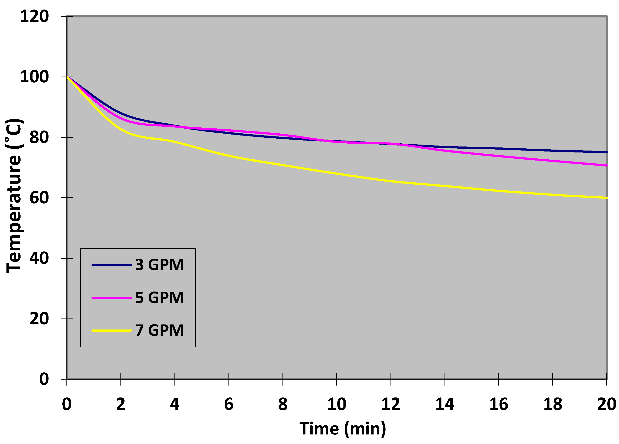
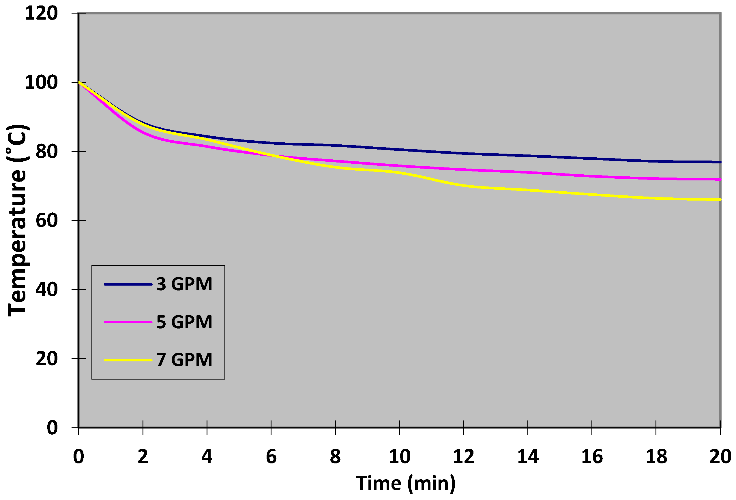
4.2. Constant Liquid Coolant with Different Flow Rates

Figure 6 illustrates the transient response of the heater block which acts as the battery pack and liquid cold plate. Only distilled water was used in this case with different flow rates at 0.3, 0.5, and 0.7 GPM. The surface temperature increased from 26 to 100 °C after switching on the heater block. Once the surface temperature reached 100 °C and a certain wait-time passed to make sure the temperature was stable, the pump and condenser were switched on and the flow rate was measured. Once the distilled water started pumping and passing through the liquid cold plate, the reading was taken. At the 0.3 GPM flow rate, the temperature dropped from 100 to 85 °C in the first 4 min. This is due to the fact that the distilled water used as a liquid coolant was able to carry away the thermal energy of the heater surface with the help of the oblique fins, which have the ability to increase the heat transfer rate from the heated plate to the liquid coolant. Then, the temperature decreased within the time period of 14 min to 79.6 °C. During the extra time period until 20 min, the temperature kept decreasing until it reached 77.8 °C. At the 0.5 GPM flow rate, the temperature dropped to 85.2 °C within 4 min. Then, it continued to drop to 77.6 °C at 14 min until it reached 75.8 °C at 20 min. The flow rate increased to 0.7 GPM and the temperature also dropped to 87.2 °C in first 4 min. Then, it dropped to 73.2 °C at 14 min. The temperature kept dropping until it reached 69.2 °C at 20 min. With this information, we observed that increasing the flow rate will reduce the temperature with the same liquid, which in this case at the temperature of 0.3 and 0.7 GPM, reached 75.8 and 69.2 °C within 20 min.
In Figure 7, the transient response of the heater block and liquid cold plate is shown. In this case, all the parameters are fixed expect for the percentage of the distilled water and ethylene glycol. In this case, 75% of distilled water and 25% of ethylene glycol are mixed and investigated with three different flow rates, 0.3, 0.5, and 0.7 GPM. The graph shows that the temperature at 0.3 GPM dropped to 88.8 °C in the first 4 min then continued to drop to 74.9 °C within 14 min. The temperature reached 71.2 °C during 20 min, while the flow rate changed to 0.5 GPM. It can be clearly seen that the temperature decreased to 76.5 °C after 4 min then the temperature kept dropping to 68.5 °C within 14 min until it reached 66.1 °C during 20 min. After the flow rate increased to 0.7 GPM, the temperature dropped to 83.4 °C within 4 min, then the temperature continued to drop to 54.4 °C and after 20 min reached 48.5 °C. Compared with the previous studies, Azmi Roslan et al. [14] experimentally studied the effect of mixed water and ethylene glycol with different percentages. It was found that the best properties for a coolant to be used are 40% of ethylene glycol and 60% of water.
In Figure 8, the transient response of the heater block and liquid cold plate are illustrated. In this case, 50% of distilled water and 50% of ethylene glycol are mixed and used in three different flow rates, 0.3, 0.5, and 0.7 GPM. At the 0.3 GPM flow rate, the temperature dropped to 84.2 °C within 4 min and continued to decrease to 75.3 °C during 14 min then dropped to 72.8 °C within 20 min. As the graph shows, at 0.5 GPM the temperature decreased to 79.5 °C within the first 4 min. Then, the temperature decreased within 14 min to 72.2 °C. During the extra time period until 20 min the temperature kept decreasing until it reached 68.2 °C. The flow rate changed from 0.5 to 0.7 GPM. Within 4 min, the temperature dropped from 100 to 80.2 °C, then dropped to 57.5 °C during 14 min, and continued to gradually drop to 51.9 °C within 20 min.
Figure 9 shows the transient response of the heater block and liquid cold plate with the same procedure of the previous cases. The only difference between the previous cases is the percentage of the distilled water and ethylene glycol. In this case, 25% of distilled water and 75% of ethylene glycol were mixed and used with different flow rates at 0.3, 0.5, and 0.7 GPM. The temperature decreased to 83.8 °C within 4 min at 0.3 GPM, then dropped to 76.8 °C within 14 min, and decreased gradually to 75.1 °C within 20 min. After switching off the system for about 40 min, the temperature of the heater block cooled down. During the first 4 min, the temperature dropped to 83.6 °C after the flow rate increased to 0.5 GPM. Within 14 min, the temperature decreased to 75.6 °C. As the graph shows, at 20 min of the 0.5 GPM flow rate the temperature reached 70.7 °C. The flow rate increased to 0.7 GPM and the temperature decreased to 78.5 °C after 4 min. The temperature of the heater block reached 63.9 °C after 14 min. During the extra time period until 20 min the temperature kept decreasing until it reached 60 °C. Compared to the previous case, the temperature reached 60 °C at the 0.7 GPM flow rate which is better than the previous case at the 0.7 GPM flow rate, which reached 69.2 °C. This is due to the fact that 75% of ethylene glycol was mixed with distilled water which has the ability to reduce the temperature of the heater block more than only using distilled water.
Figure 10 illustrates the transient response of the heater block and liquid cold plate at three different flow rates, 0.3, 0.5, and 0.7 GPM. At 0.3 GPM, 100% of ethylene glycol was used. The temperature decreased to 84.3 °C within 4 min. At 14 min, the temperature continued dropping to 78.7 °C, then reached 76.9 °C at 20 min. At the 0.5 GPM flow rate, the temperature dropped from 100 to 81.4 °C within the first 4 min. The temperature dropped gradually from 73.9 °C during the time period of 14 min. As the graph shows, the temperature reached 71.9 °C at 20 min which is better than the previous case at the 0.3 GPM flow rate. Once the liquid passed through the liquid cooled plate at 0.7 GPM, the temperature dropped to 83.4 °C within 4 min. Then, the temperature decreased slightly within the time period of 14 min to 68.8 °C. At 20 min, the temperature reached 66 °C. The results have been compared and validated with the previous simulation case study by Om et al. [27].

5. Conclusions

The safety range temperature of the electric vehicles (EV) battery can be achieved using the liquid cold plate (LCP) with oblique fins and liquid coolants, which are able to sustain the battery heat. In addition, the design of an appropriate LCP is important for cooling the electric vehicles battery, and the LCP is an effective battery cooling system. This experiment aimed to study the effect of using oblique fins in inline arrangement and liquid coolants in order to enhance the rate of heat transfer. The results of the experiment showed that the oblique fins significantly enhanced the liquid cold plate performance and the flow rate improves the heat transfer performance. At a constant temperature of 100 °C, 75% of distilled water, and 25% of ethylene glycol at the 0.7 GPM flow rate, the battery surface temperature was maintained at less than 50 °C, which is the safety range operating temperature of the electric vehicles battery.

Author Contributions

Conceptualization and writing—original manuscript, A.M.A.; visualization and supervision, R.Z.; visualization and supervision, W.A.W.G. All authors have read and agreed to the published version of the manuscript.

Funding

The researchers are grateful for the financial support provided by FRGS/1/2018/TK03/UKM/02/2 (Ministry of Education Malaysia) and Universiti Kebangsaan Malaysia (UKM).

Acknowledgments

The researchers are grateful for the financial support provided by the Ministry of Education Malaysia and the National University of Malaysia.

Conflicts of Interest

The authors declare no conflict of interest.

Nomenclature

eethylene glycol
EVelectric vehicles
HEVhybrid electric vehicles
LCPliquid cold plate
NiMHnickel-metal hydride
GPMgallon per minute
Li-ionlithium-ion
T temperature

References

  1. Pesaran, A.A.; Vlahinos, A.; Burch, S.D. Thermal Performance of EV and HEV Battery Modules and Packs; Fourteenth International Electric Vehicle Symposium; Centre for Transportation Technologies and Systems, National Renewable Energy Laboratory: Orlando, FL, USA, 1997. [Google Scholar]
  2. Xia, G.; Cao, L.; Bi, G. A review on battery thermal management in electric vehicle application. J. Power Sources 2017, 367, 90–105. [Google Scholar] [CrossRef]
  3. Xie, J.; Ge, Z.; Zang, M.; Wang, S. Structural optimization of lithium-ion battery pack with forced air cooling system. Appl. Therm. Eng. 2017, 126, 583–593. [Google Scholar] [CrossRef]
  4. Xu, X.; He, R. Research on the heat dissipation performance of battery pack based on forced air cooling. J. Power Sources 2013, 240, 33–41. [Google Scholar] [CrossRef]
  5. Kizilel, R.; Sabbah, R.; Selman, J.R.; Al-Hallaj, S. An alternative cooling system to enhance the safety of Li-ion battery packs. J. Power Sources 2009, 194, 1105–1112. [Google Scholar] [CrossRef]
  6. Kanargi, B.; Lee, P.S.; Yap, C. A numerical and experimental investigation of heat transfer and fluid flow characteristics of an air-cooled oblique-finned heat sink. Int. J. Heat Mass Transf. 2018, 116, 393–416. [Google Scholar] [CrossRef]
  7. An, Z.; Jia, L.; Li, X.; Ding, Y. Experimental investigation on lithium-ion battery thermal management based on flow boiling in mini-channel. Appl. Therm. Eng. 2017, 117, 534–543. [Google Scholar] [CrossRef]
  8. Feng, X.; Ouyang, M.; Liu, X.; Lu, L.; Xia, Y.; He, X. Thermal runaway mechanism of lithium ion battery for electric vehicles: A review. Energy Storage Mater. 2018, 10, 246–267. [Google Scholar] [CrossRef]
  9. Li, X.; Zou, C. Thermo-Physical Properties of Water and Ethylene Glycol Mixture Based SiCNanofluids: An Experimental Investigation. Int. J. Heat Mass Transfer. 2016, 101, 412–417. [Google Scholar] [CrossRef]
  10. Nambeesan, K.P.; Parthiban, R.; Kumar, K.R.; Athul, U.R.; Vivek, M.; Thirumalini, S. Experimental study of heat transfer enhancement in automobile radiator using Al2O3/water–ethylene glycol nanofluid coolants. Int. J. Automot. Mech. Eng. 2015, 12, 2857–2865. [Google Scholar] [CrossRef]
  11. Abdolbaqi, M.K.; Azwadi, C.; Mamat, R.; Azmi, W.; Najafi, G.N. Nanofluids heat transfer enhancement through STRAIGHT channel under turbulent flow. Int. J. Automot. Mech. Eng. 2015, 11, 2294–2305. [Google Scholar] [CrossRef]
  12. Balla, H.H.; Abdullah, S.; Zulkifli, R.; Faiza, W.M.; Sopian, K. Effect of Oxides Nanoparticle Materials on the Pressure Loss and Heat Transfer of Nanofluids in Circular Pipes. J. Appl. Sci. 2012, 12, 1396–1401. [Google Scholar] [CrossRef] [Green Version]
  13. Usri, N.; Azmi, W.; Mamat, R.; Hamid, K.A. Forced convection heat transfer using water- ethylene glycol (60:40) based nanofluids in automotive cooling system. Int. J. Automot. Mech. Eng. 2015, 11, 2747–2755. [Google Scholar] [CrossRef]
  14. Azmi Roslan, A.M.; Tukiman, N.; Ibrahim, N.N.; Juanil, A.R. The Effects of Ethylene Glycol to Ultrapure Water on Its Specific Heat Capacity and Freezing Point. J. Appl. Environ. Biol. Sci. 2017, 7, 54–60. [Google Scholar]
  15. Panchal, S. Impact of Vehicle Charge and Discharge Cycles on the Thermal Characteristics of Lithiumion Batteries. Master’s Thesis, University of Waterloo, Waterloo, ON, Canada, 2014. [Google Scholar]
  16. Zhao, J.; Rao, Z.; Li, Y. Thermal performance of mini-channel liquid cooled cylinder based battery thermal management for cylindrical lithium-ion power battery. Energy Convers. Manag. 2015, 103, 157–165. [Google Scholar] [CrossRef]
  17. Panchal, S.; Khasow, R.; Dincer, I.; Agelin-Chaab, M.; Fraser, R.; Fowler, M. Thermal design and simulation of mini-channel cold plate for water cooled large sized prismatic lithium-ion battery. Appl. Therm. Eng. 2017, 122, 80–90. [Google Scholar] [CrossRef]
  18. Huo, Y.; Rao, Z.; Liu, X.; Zhao, J. Investigation of power battery thermal management by using mini-channel cold plate. Energy Convers. Manag. 2015, 89, 387–395. [Google Scholar] [CrossRef]
  19. Karimi, G.; Dehghan, A.R. Thermal Management Analysis of a Lithium-Ion Battery Pack using Flow Network Approach. Int. J. Mech. Eng. Mechatron. 2012, 1, 88–94. [Google Scholar] [CrossRef] [Green Version]
  20. Jin, L.; Lee, P.; Kong, X.; Fan, Y.; Chou, S. Ultra-thin minichannel LCP for EV battery thermal management. Appl. Energy 2014, 113, 1786–1794. [Google Scholar] [CrossRef]
  21. Lee, Y.J.; Lee, P.S.; Chou, S.K. Enhanced Thermal Transport in Microchannel Using Oblique Fins. J. Heat Transf. 2012, 134, 101901. [Google Scholar] [CrossRef]
  22. Prajapati, Y.K.; Pathak, M.; Khan, M.K. A comparative study of flow boiling heat transfer in three different configurations of microchannels. Int. J. Heat Mass Transf. 2015, 85, 711–722. [Google Scholar] [CrossRef]
  23. Wang, C.-C.; Chang, W.-J.; Dai, C.-H.; Lin, Y.-T.; Yang, K.-S. Effect of inclination on the convective boiling performance of a microchannel heat sink using HFE-7100. Exp. Therm. Fluid Sci. 2012, 36, 143–148. [Google Scholar] [CrossRef]
  24. Li, X.; Zhou, D.; Zhang, G.; Wang, C.; Lin, R.; Zhong, Z. Experimental investigation of the thermal performance of silicon cold plate for battery thermal management system. Appl. Therm. Eng. 2019, 155, 331–340. [Google Scholar] [CrossRef]
  25. Lee, Y.J.; Singh, P.K.; Lee, P.S. Fluid flow and heat transfer investigations on enhanced microchannel heat sink using oblique fins with parametric study. Int. J. Heat Mass Transf. 2015, 81, 325–336. [Google Scholar] [CrossRef]
  26. Law, M.; Lee, P.S. A comparative study of experimental flow boiling heat transfer and pressure characteristics in straight- and oblique-finned microchannels. Int. J. Heat Mass Transfer. 2015, 85, 797–810. [Google Scholar] [CrossRef]
  27. Om, N.I.; Zulkifli, R.; Gunnasegaran, P. Influence of the oblique fin arrangement on the fluid flow and thermal performance of liquid cold plate. Case Stud. Therm. Eng. 2018, 12, 717–727. [Google Scholar] [CrossRef]
Figure 1. (a) Battery’s liquid cold plate system. (b) Liquid cold plate (LCP) and oblique fin dimension. (c) LCP with oblique fin arrangement. (d) The direction of the fluid flow.
Wevj 12 00055 g001aWevj 12 00055 g001b
Figure 2. Image of the experimental configuration.
Wevj 12 00055 g002
Figure 3. Surface temperature of the heater block for different liquid coolants at the 0.3 GPM flow rate.
Wevj 12 00055 g003
Figure 4. Surface temperature of the heater block for different liquid coolants at the 0.5 GPM flow rate.
Wevj 12 00055 g004
Figure 5. Surface temperature of the heater block for different liquid coolants at the 0.7 GPM flow rate.
Wevj 12 00055 g005
Figure 6. Surface temperature for the 100% distilled water.
Wevj 12 00055 g006
Figure 7. Surface temperature for 75% of distilled water mixed with 25% of ethylene glycol.
Wevj 12 00055 g007
Figure 8. Surface temperature for 50% of distilled water mixed with 50% of ethylene glycol.
Wevj 12 00055 g008
Figure 9. Surface temperature for 25% of distilled water mixed with 75% of ethylene glycol.
Wevj 12 00055 g009
Figure 10. Surface temperature for 100% of ethylene glycol.
Wevj 12 00055 g010
Publisher’s Note: MDPI stays neutral with regard to jurisdictional claims in published maps and institutional affiliations.

