An Intelligent Adaptive Neural Network Controller for a Direct Torque Controlled eCAR Propulsion System


Abstract
1. Introduction
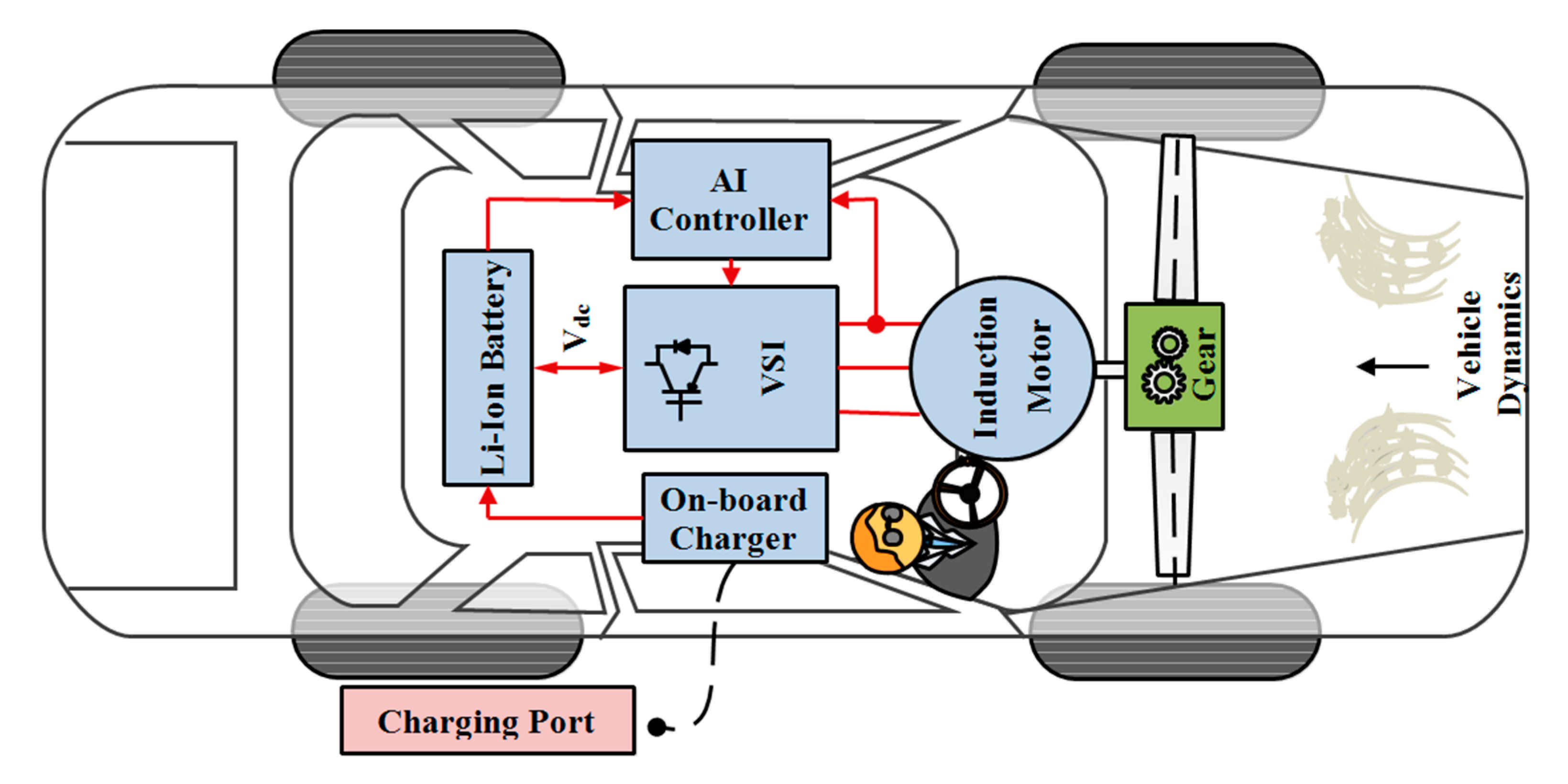
2. Components of an eCAR Powertrain
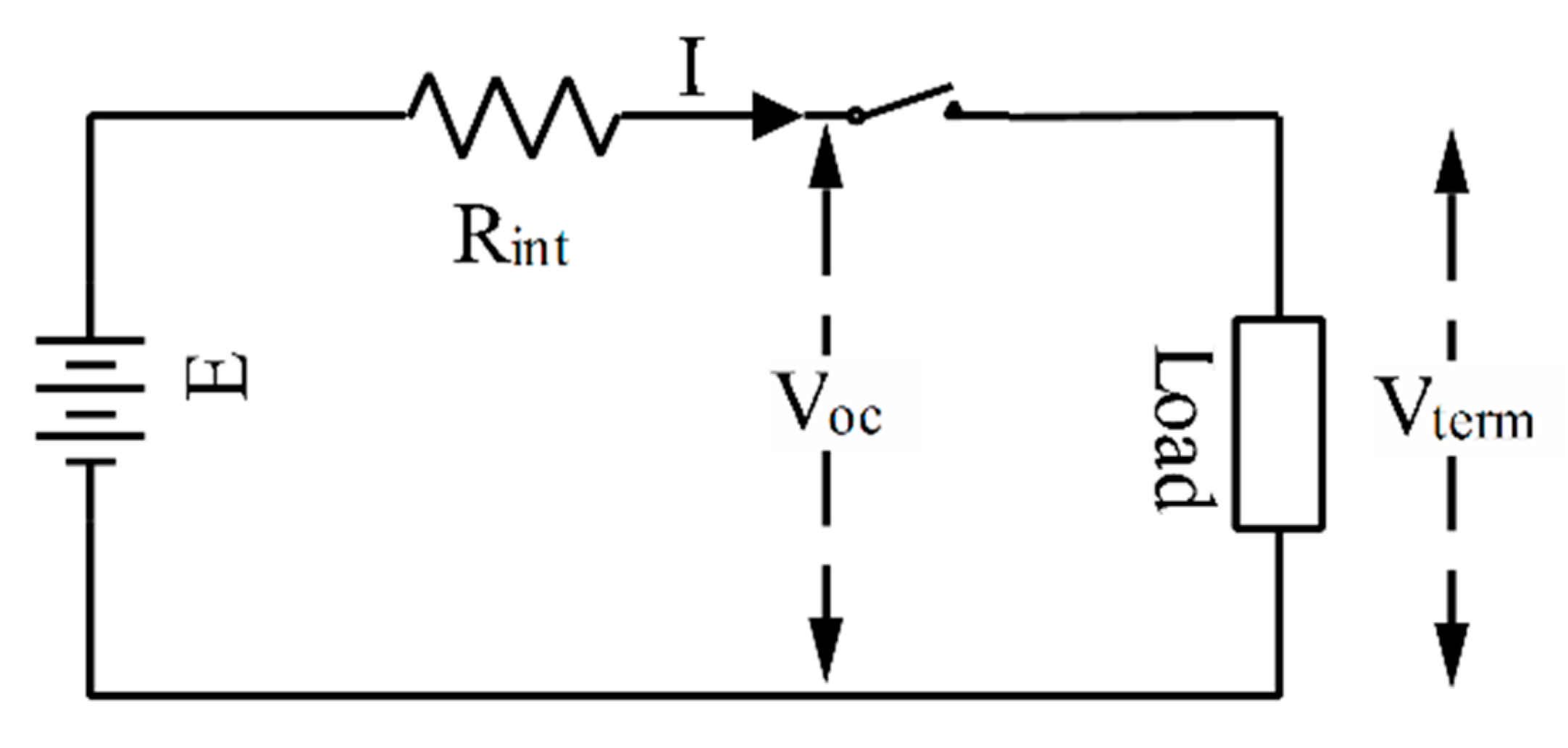
2.1. Battery Model
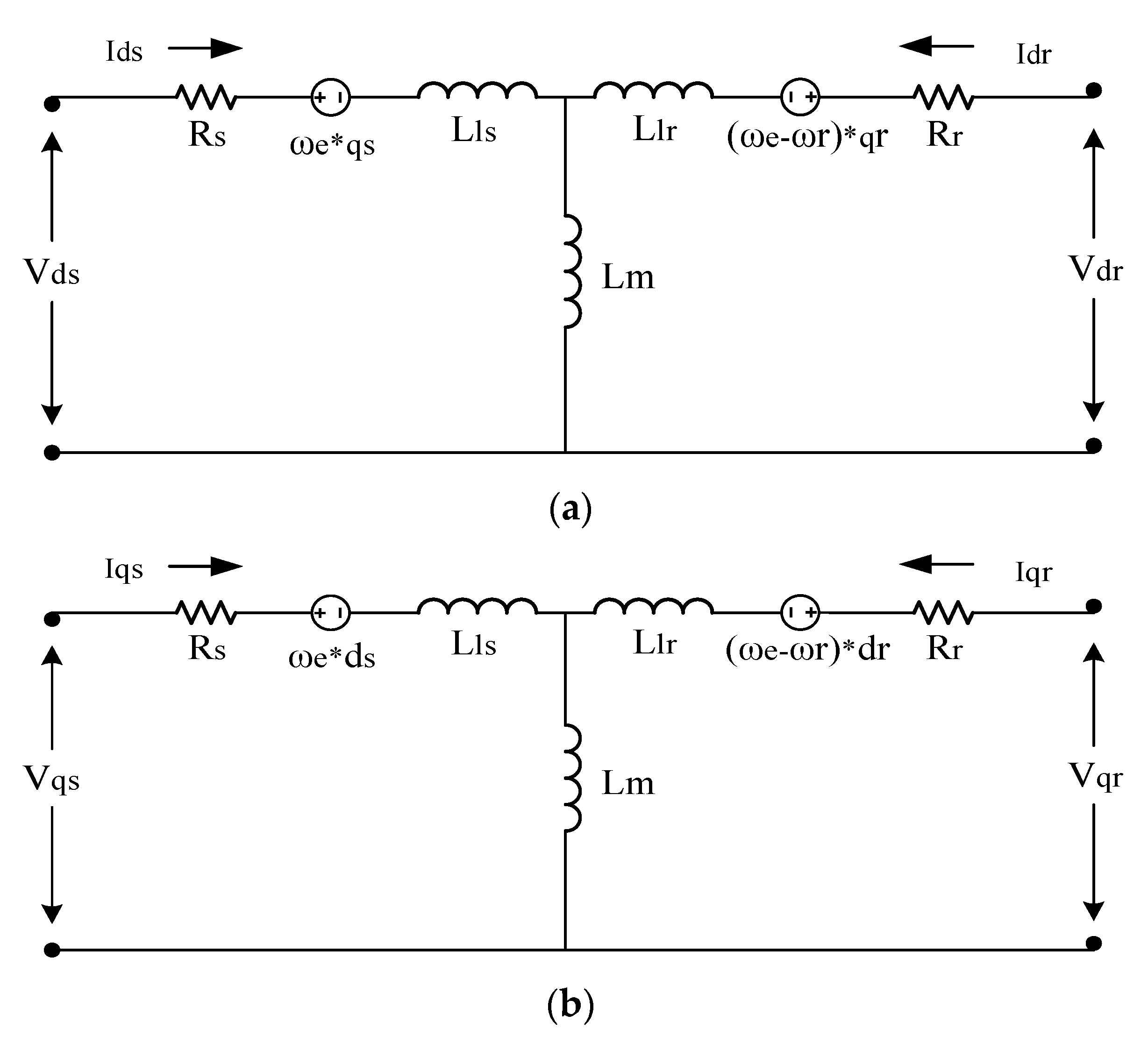
2.2. Motor Model
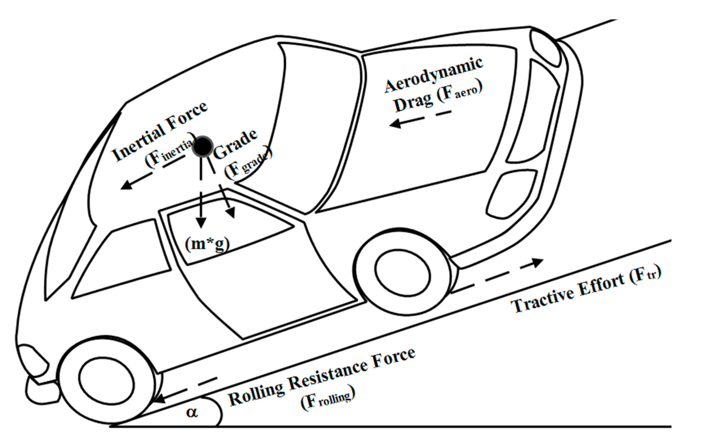
2.3. Glider Model
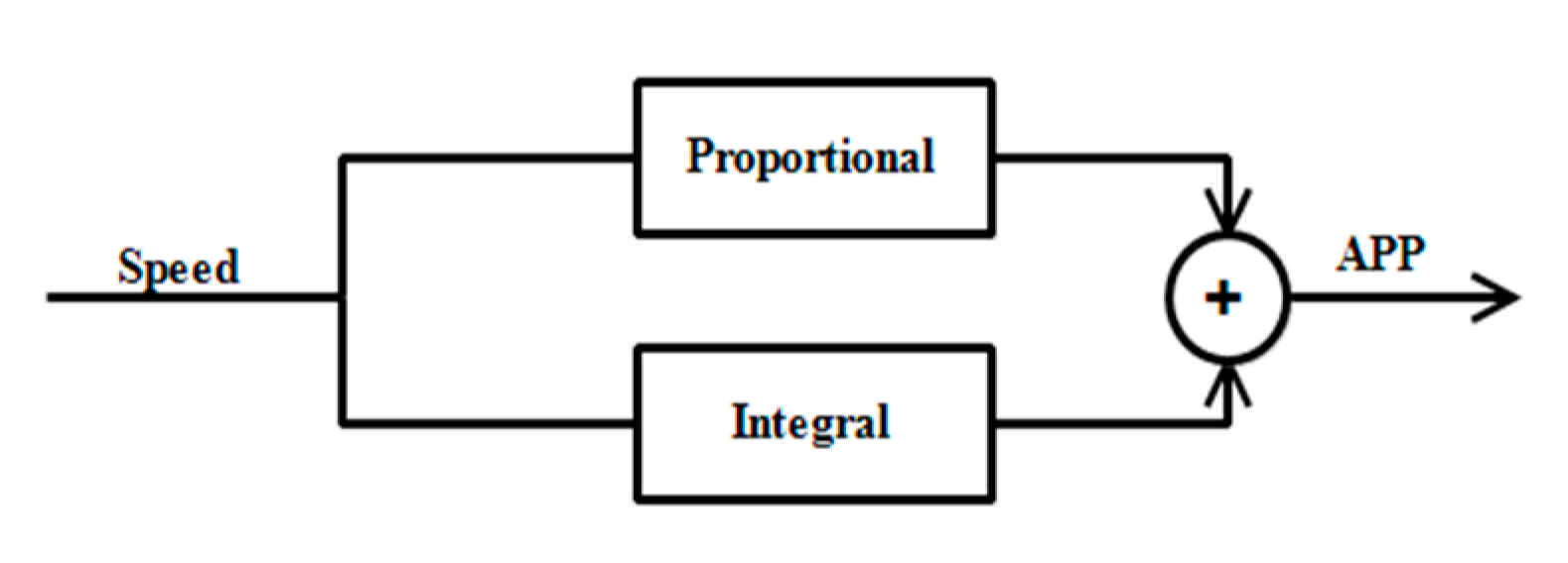
2.4. Driver Model
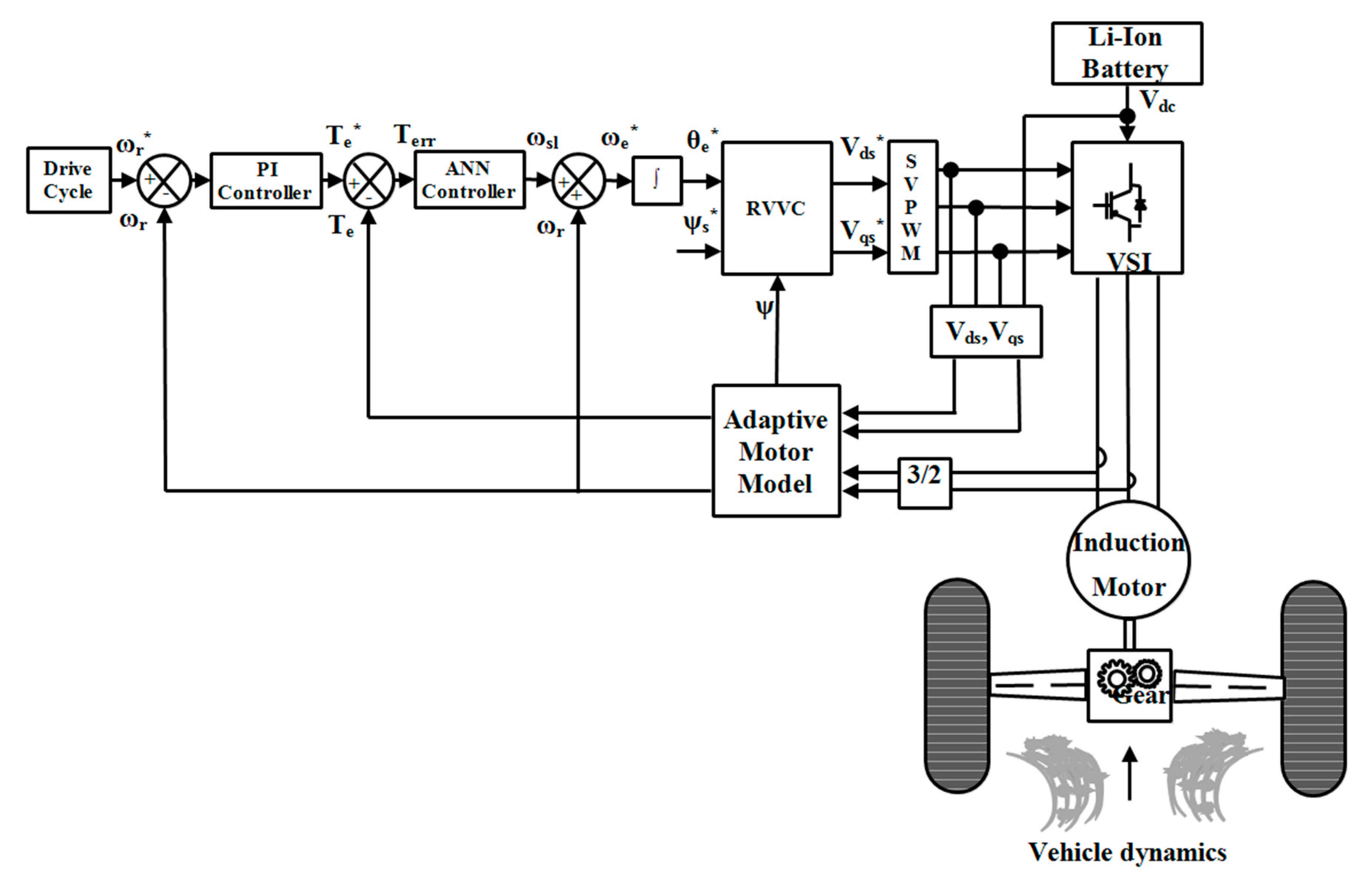
3. Direct Torque Controlled eCAR
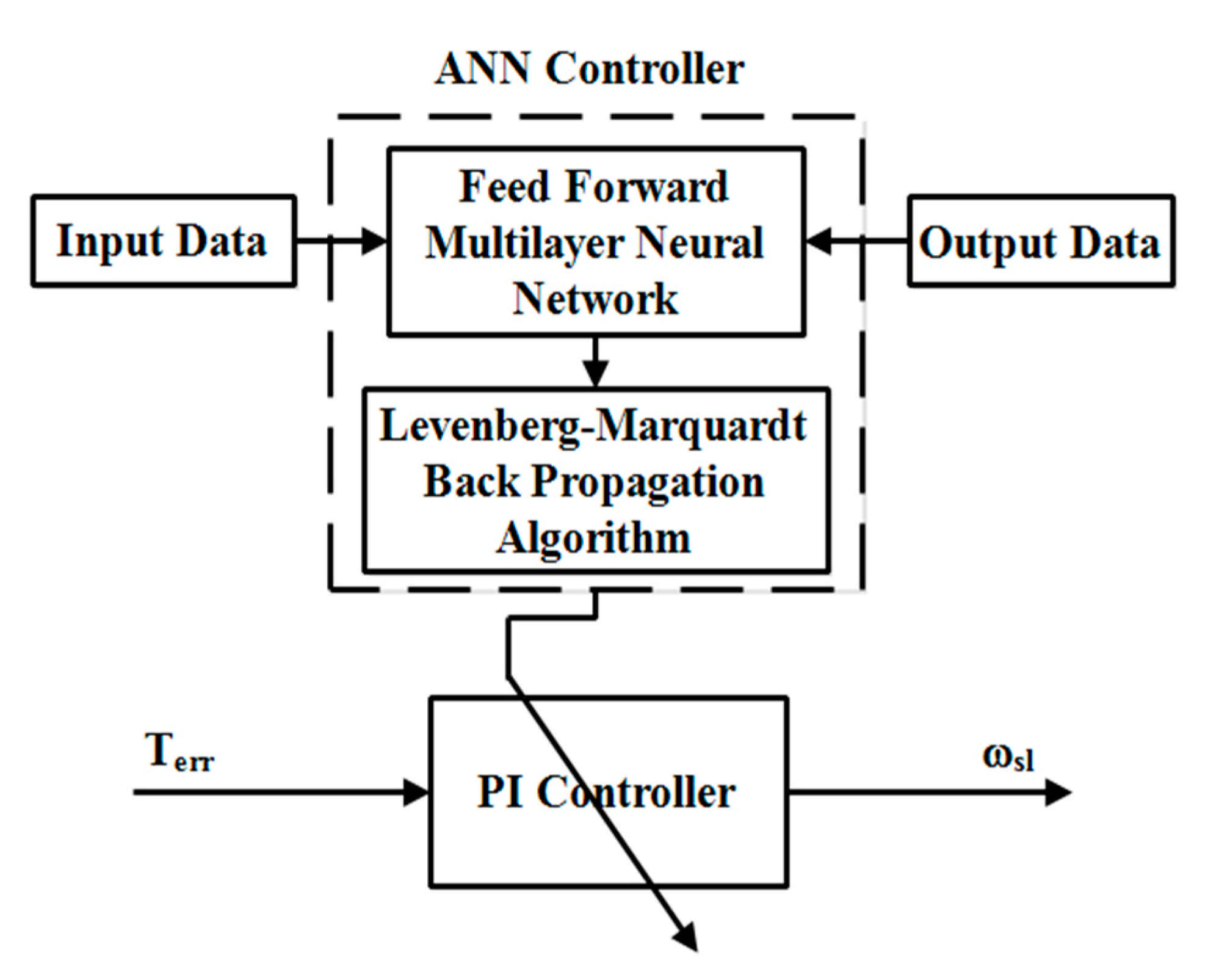
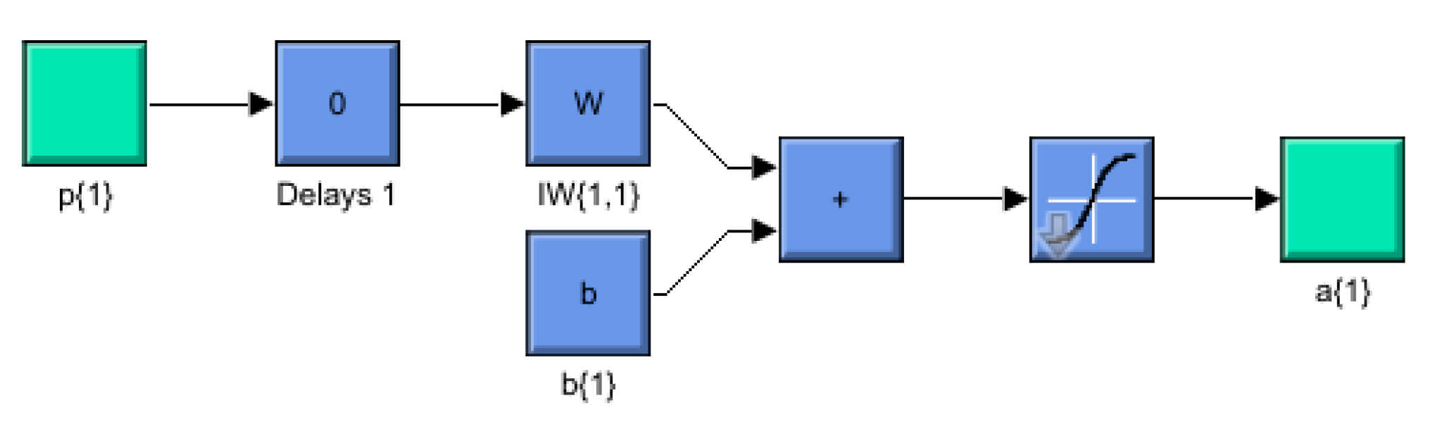
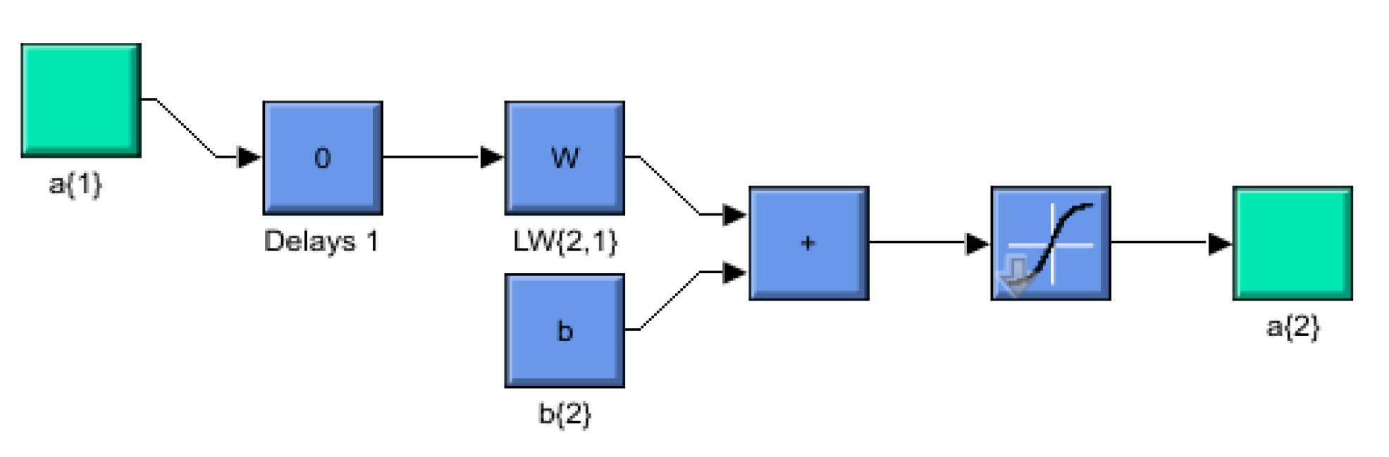
4. ANN Controller
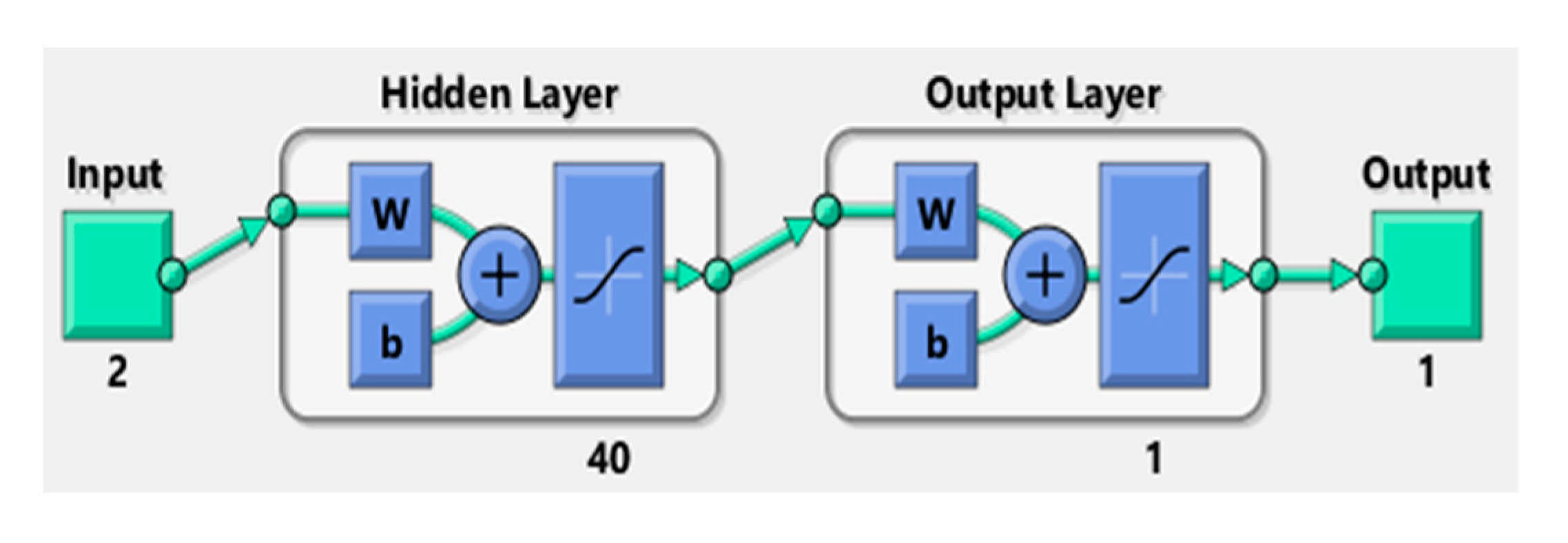
- Step 1: Firstly, torque error and the change in torque error are given as inputs to the network. The input vector matrix is given by [X] 2 × 1 with two inputs.
- Step 2: Subsequently, the targets are chosen in order to attain the desired variables of the network. The target vector matrix is given by [t] 1 × 1 with one output.
- Step 3: The weights and biases are then initialized and are updated corresponding to Levenberg–Marquardt optimization algorithm. The output vector matrix is given by [y] where [w]° and [b]° are the weights and biases row matrices, respectively.
- Step 4: The ANN is trained by using the data provided in Step 1 and Step 2, respectively, and by fixing the goal parameter to a minimum. The error data in the form of an error vector matrix (E) is generated to confirm that the desired convergence of the specified goal parameters or epochs during training has been met then training stops.where E is the error data matrix obtained using a mean squared error as the objective function, n is the total number of outputs and I is the number of iterations.
- Step 5: After the training the network, the optimized value of the steady state error as the output is yielded.
- Step 6: The optimized steady state error output is applied as the input to the PI controller in order to produce the slip speed.
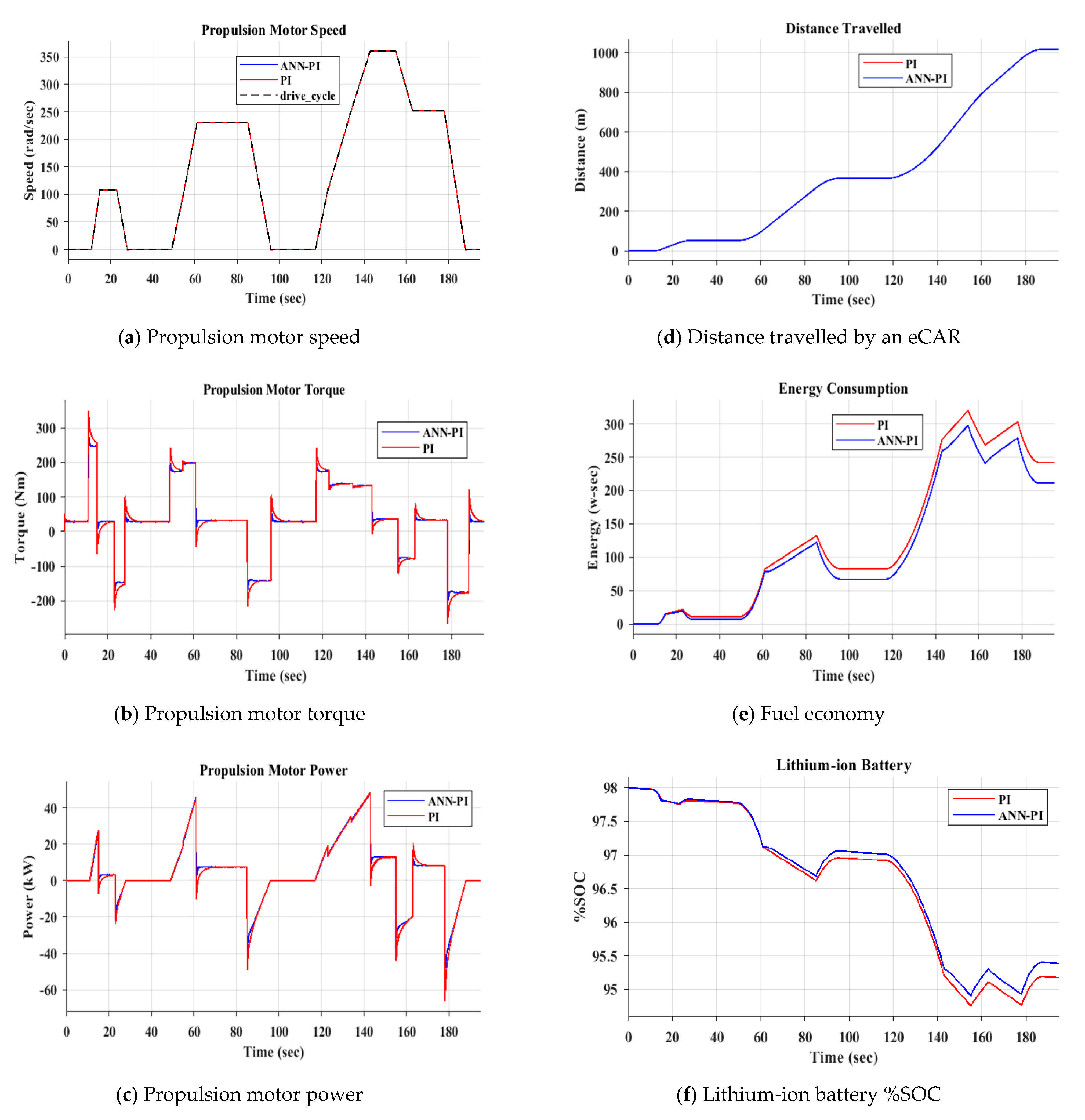
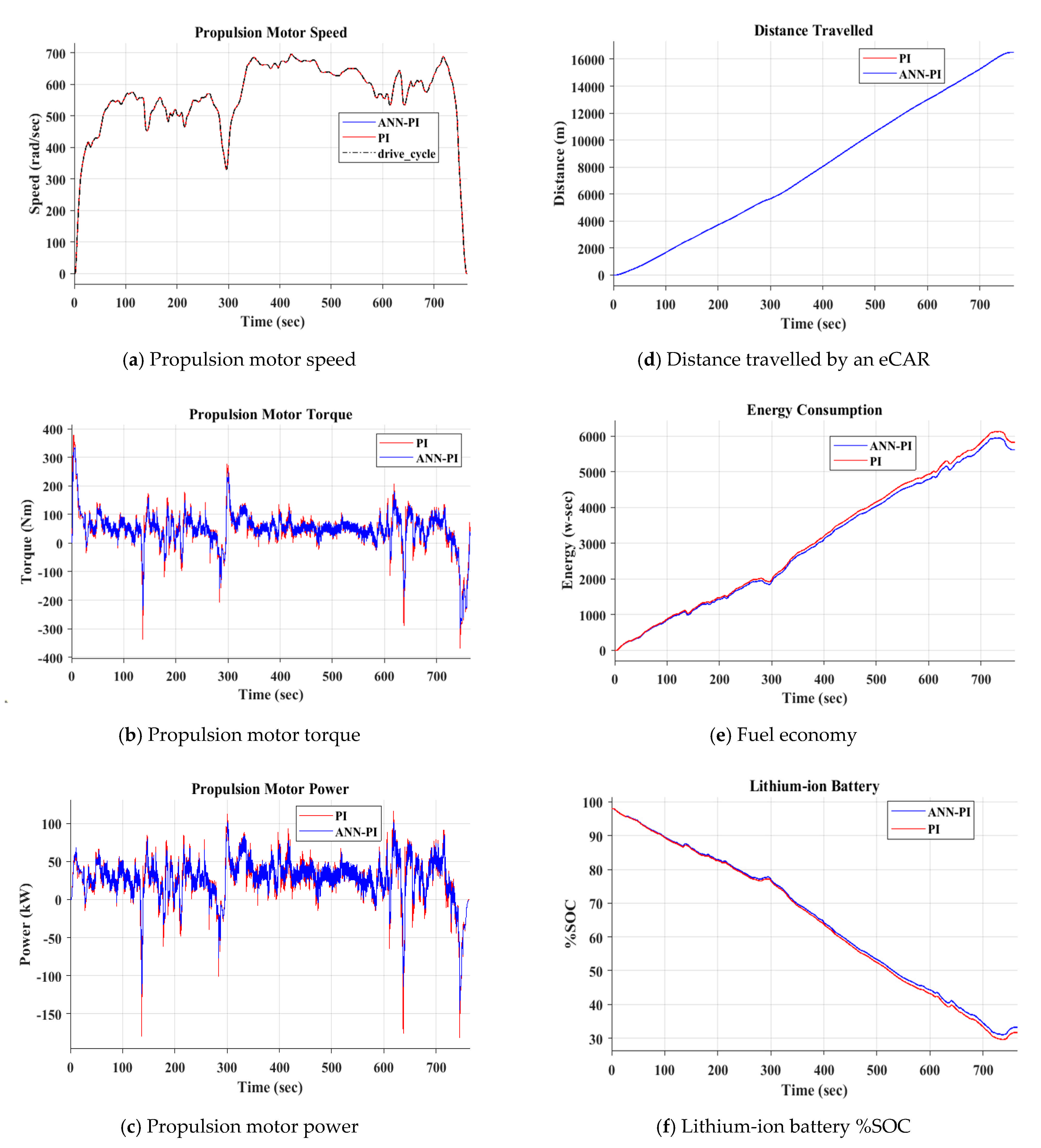
5. Simulation Analysis of an eCAR
6. Conclusions
Author Contributions
Funding
Conflicts of Interest
References
- Yu, Y.; Jiang, J.; Min, Z.; Wang, P.; Shen, W. Research on Energy Management Strategies of Extended-Range Electric Vehicles Based on Driving Characteristics. World Electr. Veh. J. 2020, 11, 54. [Google Scholar] [CrossRef]
- Un-Noor, F.; Padmanaban, S.; Mihet-Popa, L.; Mollah, M.N.; Hossain, E. A Comprehensive Study of Key Electric Vehicle (EV) Components, Technologies, Challenges, Impacts, and Future Direction of Development. Energies 2017, 10, 1217. [Google Scholar] [CrossRef]
- El Ouanjli, N.; Derouich, A.; El Ghzizal, A.; Motahhir, S.; Chebabhi, A.; El Mourabit, Y.; Taoussi, M. Modern improvement techniques of direct torque control for induction motor drives—A review. Prot. Control Mod. Power Syst. 2019, 4, 11. [Google Scholar] [CrossRef]
- Rao, G.M.; Srikanth, G. Comparative Study of Maximum Torque Control by PI ANN of Induction Motor. Int. J. Appl. Eng. Res. 2018, 13, 4620–4625. [Google Scholar]
- Halvaei, A.; Khoei, H. Sensorless Direct Power Control of Induction Motor Drive Using Artificial Neural Network. Adv. Artif. Neural Syst. 2015, 2015, 1–9. [Google Scholar] [CrossRef] [PubMed]
- Jadhav, S.V.; Kirankumar, J.; Chaudhari, B.N. ANN based intelligent control of Induction Motor drive with Space Vector Modulated DTC. In Proceedings of the IEEE International Conference on Power Electronics, Drives and Energy Systems (PEDES), Bengaluru, India, 16–19 December 2012; pp. 1–6. [Google Scholar]
- Verma, B.S.; Yadav, D. Investigation of ANN tuned PI speed controller of a modified DTC induction motor drive. In Proceedings of the IEEE International Conference on Power Electronics, Drives and Energy Systems (PEDES), Mumbai, India, 16–19 December 2014; pp. 1–6. [Google Scholar]
- Habetler, T.G.; Profumo, F.; Pastorelli, M.; Tolbert, L.M. Direct torque control of induction machines using space vector modulation. IEEE Trans. Ind. Appl. 1992, 28, 1045–1053. [Google Scholar] [CrossRef]
- Brahmananda, R.T.; Amarnath, J.; Subba, R.D. New hybrid SVPWM methods for direct torque controlled induction motor drive for reduced current ripple. In Proceedings of the 2006 International Conference on Power Electronic, Drives and Energy Systems, PEDES’06, New Delhi, India, 12–15 December 2006; p. 3B-20. [Google Scholar]
- Reddy, T.B.; Amarnath, J.; Subbarayudu, D.; Khan, M.H. Generalized discontinuous PWM based direct torquecontrolled induction motor drive with a sliding mode speed controller. In Proceedings of the 2006 International Conference on Power Electronic, Drives and Energy Systems Indu Growth, PEDES’06, New Delhi, India, 12–15 December 2006; p. 3D-11. [Google Scholar]
- Reza, C.M.F.S.; Islam, M.D.; Mekhilef, S. A review of reliable and energy efficient direct torque controlled induction motor drives. Renew. Sustain. Energy Rev. 2014, 37, 919–932. [Google Scholar] [CrossRef]
- Sri Gowri, K.; Reddy, T.B.; Sai Babu, C. Direct torque control of induction motor based on advanced discontinuous PWM algorithm for reduced current ripple. Electr. Eng. 2010, 92, 245–255. [Google Scholar] [CrossRef]
- Gowri, K.S.; Reddy, T.B.; Babu, C.S. High-Performance Generalized ADPWM Algorithm for VSI Fed IM Drives for Reduced Switching Losses. Int. J. Recent Trends Eng. 2009, 2, 2009. [Google Scholar]
- Sagar, Y.C.; Gowri, K.S.; Kumaraswamy, G. Implementation of dSPACE Controlled CSVPWM Based Induction Motor Drive. Int. J. Eng. Res. Technol. IJERT 2013, 2, 1070–1075. [Google Scholar]
- Aygun, H.; Aktas, M. A novel DTC method with efficiency improvement of IM for EV applications. Eng. Technol. Appl. Sci. Res. 2018, 8, 3456–3462. [Google Scholar] [CrossRef]
- Tummala, S.K.; Dhasharatha, G. Artificial Neural Networks based SPWM technique for speed control of Permanent Magnet Synchronous Motor. In Proceedings of the E3S Web of Conferences, SeFet 2019: 1st International Conference on Sustainable Energy and Future Electric Transportation, Gokaraju Rangaraju Institute of Engineering & Technology, Hyderabad, India, 14–16 February 2019; Volume 87, p. 01030. [Google Scholar]
- Jia, Z.; Kim, B. Direct Torque Control with Adaptive PI Speed Controller based on Neural Network for PMSM Drives. In Proceedings of the MATEC Web Conferences, International Conference on Electrical Engineering, Control and Robotics (EECR 2018), Chengdu, China, 12–14 January 2018; Volume 160, p. 02011. [Google Scholar]
- Rao, V.M.V.; Kumar, A.A. Artificial Neural Network and Adaptive Neuro Fuzzy Control of Direct Torque Control of Induction Motor for Speed and Torque Ripple Control. In Proceedings of the 2018 2nd International Conference on Trends in Electronics and Informatics (ICOEI), Tirunelveli, India, 11–12 May 2018; pp. 1416–1422. [Google Scholar]
- Djeriri, Y.; Meroufel, A.; Massoum, A. Artificial neural network based direct torque control of doubly fed induction generator. J. Electr. Eng. 2014, 14, 71–79. [Google Scholar]


| 3Ф, AC Induction Motor | |
|---|---|
| Motor Power, Pm | 90 kW |
| Nominal Voltage, Vn | 380 V, RMS |
| Current Rating, In | 200 A |
| Variable Frequency, fs | 0–400 Hz |
| Constant Power | 90 kW @ 12,000 rpm |
| Constant Torque | 120 N-m @ 7200 rpm |
| Motor Inertia, J | 1.5 kg-m2 |
| Stator Resistance, Rs | 0.021 Ohms |
| Rotor Resistance, Rr | 0.016 Ohms |
| Stator Reactance, Lls | 0.0164 Henry |
| Rotor Reactance, Llr | 0.0167 Henry |
| Mutual Inductance, Lm | 0.016 Henry |
| Number of Poles, P | 4 |
| Nominal Stator Flux, ψs | 0.98 Wb |
| Vehicle Dynamics | |
|---|---|
| Mass of the vehicle, m | 1200 Kg |
| Frontal area of the vehicle, Af | 0.2 sq. mt |
| Wheel radius, Rw | 0.2794 m |
| Coefficient of rolling resistance, Crr | 0.0015 |
| Air density, | 1.225 Kg/m3 |
| Air drag coefficient, Cd | 0.3 |
| Gravitational constant, g | 9.81 Kg/m2 |
| Transmission gear ratio, G | 6.842 |
| Slope or gradient angle, α | 5° |
| Constant A | 74.28 |
| Constant B | 2.139 |
| Constant C | 0.3922 |
| Variables | Values |
|---|---|
| Number of neurons | 40 |
| Hidden layer transfer function | Tansig |
| Output layer transfer | Purlin |
| Activation function | Net sum |
| Gradient | 1.1045 × 10⁻⁶ |
| Regression | 0.9897 |
| Training sets | 100 |
| Testing sets | 50 |
| Training method | Levenberg–Marquardt back-propagation |
| Optimization function | Mean square error (MSE) |
| Learning method | Gradient descent weight and bias |
| S. No | Input 1 | Input 2 | Output | Error | Target |
|---|---|---|---|---|---|
| 1 | 0 | 0 | 282.9359 | −282.936 | 0 |
| 2 | 0.288448 | 9951.406 | 280.8798 | −272.321 | 8.558594 |
| 3 | −0.13429 | 9506.473 | 290.7358 | −275.806 | 14.9301 |
| 4 | −0.09254 | 9109.208 | 289.5684 | −270.595 | 18.97366 |
| 5 | −0.09145 | 8760.206 | 289.3706 | −267.585 | 21.78575 |
| 6 | 0.676865 | 8492.981 | 270.4763 | −247.518 | 22.95849 |
| 7 | −0.19752 | 8213.084 | 291.5531 | −266.385 | 25.16803 |
| 8 | −0.82494 | 7985.73 | 305.1781 | −278.464 | 26.7146 |
| 9 | −0.57358 | 7827.065 | 299.7575 | −272.655 | 27.10218 |
| 10 | 1.383714 | 7761.038 | 251.6016 | −226.022 | 25.57983 |
| Torque Controller Constants | Kp | Ki |
|---|---|---|
| Conventional Controller | 0.2870 | 0.0167 |
| ANN Controller | 0.2137 | 0.01 |
| Drive Cycle | ECE (R15) | HWFET | NYCC | ||||
|---|---|---|---|---|---|---|---|
| Parameters | PI | ANN-PI | PI | ANN-PI | PI | ANN-PI | |
| Avg torque ripple (Nm) | 28 | 4 | 12 | 2 | 10 | 2 | |
| Avg flux ripple (wb) | 0.3 | 0.15 | 0.2 | 0.14 | 0.18 | 0.12 | |
| Avg fuel consumption (J) | 120 | 102 | 3250 | 3133 | 250 | 176 | |
| Avg output power (kW) | 50 | 48 | 120 | 90 | 145 | 115 | |
Publisher’s Note: MDPI stays neutral with regard to jurisdictional claims in published maps and institutional affiliations. |
© 2021 by the authors. Licensee MDPI, Basel, Switzerland. This article is an open access article distributed under the terms and conditions of the Creative Commons Attribution (CC BY) license (http://creativecommons.org/licenses/by/4.0/).
Share and Cite
Banda, G.; Kolli, S.G. An Intelligent Adaptive Neural Network Controller for a Direct Torque Controlled eCAR Propulsion System. World Electr. Veh. J. 2021, 12, 44. https://doi.org/10.3390/wevj12010044
Banda G, Kolli SG. An Intelligent Adaptive Neural Network Controller for a Direct Torque Controlled eCAR Propulsion System. World Electric Vehicle Journal. 2021; 12(1):44. https://doi.org/10.3390/wevj12010044
Chicago/Turabian StyleBanda, Gururaj, and Sri Gowri Kolli. 2021. "An Intelligent Adaptive Neural Network Controller for a Direct Torque Controlled eCAR Propulsion System" World Electric Vehicle Journal 12, no. 1: 44. https://doi.org/10.3390/wevj12010044
APA StyleBanda, G., & Kolli, S. G. (2021). An Intelligent Adaptive Neural Network Controller for a Direct Torque Controlled eCAR Propulsion System. World Electric Vehicle Journal, 12(1), 44. https://doi.org/10.3390/wevj12010044