Review

Beyond the State of the Art of Electric Vehicles: A Fact-Based Paper of the Current and Prospective Electric Vehicle Technologies

1
Mobility, Logistics and Automotive Technology Research Centre (MOBI), Department of Electrical Engineering and Energy Technology (ETEC), Faculty of Engineering, Vrije Universiteit Brussel (VUB), 1050 Brussel, Belgium
2
Flanders Make, 3001 Heverlee, Belgium
*
Author to whom correspondence should be addressed.
World Electr. Veh. J. 2021, 12(1), 20; https://doi.org/10.3390/wevj12010020
Submission received: 30 November 2020 / Revised: 30 December 2020 / Accepted: 29 January 2021 / Published: 3 February 2021
(This article belongs to the Special Issue Feature Papers in World Electric Vehicle Journal in 2021)

Abstract

:
Today, there are many recent developments that focus on improving the electric vehicles and their components, particularly regarding advances in batteries, energy management systems, autonomous features and charging infrastructure. This plays an important role in developing next electric vehicle generations, and encourages more efficient and sustainable eco-system. This paper not only provides insights in the latest knowledge and developments of electric vehicles (EVs), but also the new promising and novel EV technologies based on scientific facts and figures—which could be from a technological point of view feasible by 2030. In this paper, potential design and modelling tools, such as digital twin with connected Internet-of-Things (IoT), are addressed. Furthermore, the potential technological challenges and research gaps in all EV aspects from hard-core battery material sciences, power electronics and powertrain engineering up to environmental assessments and market considerations are addressed. The paper is based on the knowledge of the 140+ FTE counting multidisciplinary research centre MOBI-VUB, that has a 40-year track record in the field of electric vehicles and e-mobility.

1. Introduction

Within the current electric vehicle (EV) evolution and electrification strategy towards more and more green and sustainable transport, there are key technological barriers and challenges, which are frequently changing from stakeholders’ perspectives [1]. A decade ago, surveys [2] have pointed out that the three main barriers for the market introduction of electric vehicles (EV) were purchase price, driving range and availability of charging infrastructure. However, these key barriers have changed drastically. The cost of the battery—the most expensive component of the EV propulsion system—has dropped down nearly 90% [3,4]. Purchase price parity is expected by 2025 at the latest. From then onwards electric vehicles will be cheaper to buy compared to conventional vehicles. Knowing that the running cost and maintenance cost are already cheaper today, this means that the total cost of ownership (TCO) will be cheaper in the coming years. The driving range increased from between 100–150 km up to 400+ km [5,6,7]. In most countries, the availability of charging infrastructure is still an issue, especially for people living in urban areas and who often have no private parking place. EVs have proven to be better for the environment [8,9] and allow a higher penetration of renewable energy sources in the electricity grid [10].
Which developments have made it possible to reach such impressive improvements? Was it only due to mass market production—upscaling the production capacity or also due to technological improvements—or choices of materials and designs? And what is needed for further improvements in driving range and cost reduction or grid integrations?
This paper will tackle these questions and more. This with a focus on innovative technological developments [11,12,13].
The specific energy of the battery has been improved from 110 Wh/kg in 2010 to 250 Wh/kg in 2020. This can further be improved up to 450 Wh/kg by 2030. In the same time the battery energy density will increase from 310 Wh/L in 2010 and 580 Wh/L today up to 1100 Wh/L by 2030. The battery cost has reduced from 1000 €/kWh to 130 €/kWh and is expected to further decrease below 80 €/kWh. How all this can be achieved is explained in Section 3 about the battery technology. It is mainly based on finding suitable electrolytes for high voltage cathodes. A higher specific energy will lead to an increased driving range or a lower vehicle weight and this at a lower battery cost. The size of the battery in 2010 was typically 30 kWh; today 60 kWh is not an exception anymore and by 2030 the battery capacity will be over 80kWh.
The traction inverter power density is improved from 10 kW/L in 2010 to 30 kW/L in 2020 and can further be improved up to 65 kW/L in 2030 depending on the DC-link voltage, which results in a volume reduction up to 40%. In the same time the peak inverter efficiency has increased from 92% (2010) to 96% (2020) and can be further improved up to 98% by introducing the wide bandgap technology in the drive system. This will enhance the driving range up to 8%. More info can be found in Section 2. A similar trend can be observed for the battery charger and DC/DC converters, where efficiencies up to 99% could be achieved by 2030, leading to a reduction of the charging cost by 20%. The progress of charging infrastructure is explained in Section 4. Improved efficiencies will result in a reduction in the vehicle energy consumption up to 32% (from 0,22 kWh/km down to 0.15 kWh/km).
The environmental impact of electric vehicles mainly depends on how electricity is produced. Based on the EU energy mix the CO2 emissions were around 300 CO2 g/kWh in 2010. It is expected, by an increased share of renewable energy sources and even considering phasing out nuclear power plants, that by 2030 the CO2 emissions would reduce below at least 200 CO2 g/kWh, as explained in Section 5. Considering the electric vehicle consumption and emissions to produce the electricity, the CO2 emissions per vehicle will decrease from 66 CO2 g/km in 2010 to below 30 CO2 g/km in 2030.
By 2030 autonomous vehicles (AV) are expected to come into play. Most likely they will be electric and shared. While Level 1 automation (SAE) had already been introduced in some commercial vehicles by 2010, current state-of-the art in commercial vehicles is at level 3 for and at level 4 for specific pilot projects. With advances in artificial intelligence and communication technology, the level of automation is expected to have evolved to widespread level 4 automation by 2030, which will open the way to new and shared mobility services. This progress is described in Section 6.
As such the paper is structured as follows: It starts from the overall vehicle propulsion design based on a digital twin (DT) approach. Next, the advantages of the novel wide bandgap (WBG) technology used as semiconductors in power converters are described. Then, the battery technologies and their advances, as EV key component, mainly based on solid-state batteries are tackled. Furthermore, the advances in ultra-high fast battery chargers are elaborated. More and more these battery chargers will become bidirectional systems allowing vehicle-to-grid (V2G) or V2X features (such as vehicle-to-home (V2H), vehicle-to-building (V2B) and vehicle-to-device (V2D)). This will open a smart interaction and management with the grid network towards Sustainable Energy Communities, where renewable energy sources are seamlessly integrated with EVs. The way electricity is produced defines the environmental performance of EVs. The last part of this paper tackles the current developments in autonomous electric vehicles (AEVs), with a focus on shared autonomous electric vehicles (SAEV) and its robust optical vehicle wireless communications in vehicle-to-vehicle (V2V) and vehicle-to-infrastructure (V2I), which have an impact on the developed management strategies and their interactions with the available charging infrastructure [14,15,16].

2. The Next Generation EV Propulsion Systems

EV propulsion systems are very simple from a concept point of view [17]: A battery, power converter, an electric motor and a fixed transmission. No clutch, no gearbox, no oil filters, etc. are needed. However, to reduce cost and improve driving range and driving comfort, even more, novel approaches are required. They are often based on top-notch simulation models [18,19,20,21]. This section gives insights into the next generation of the EV systems and future trends and new directions.

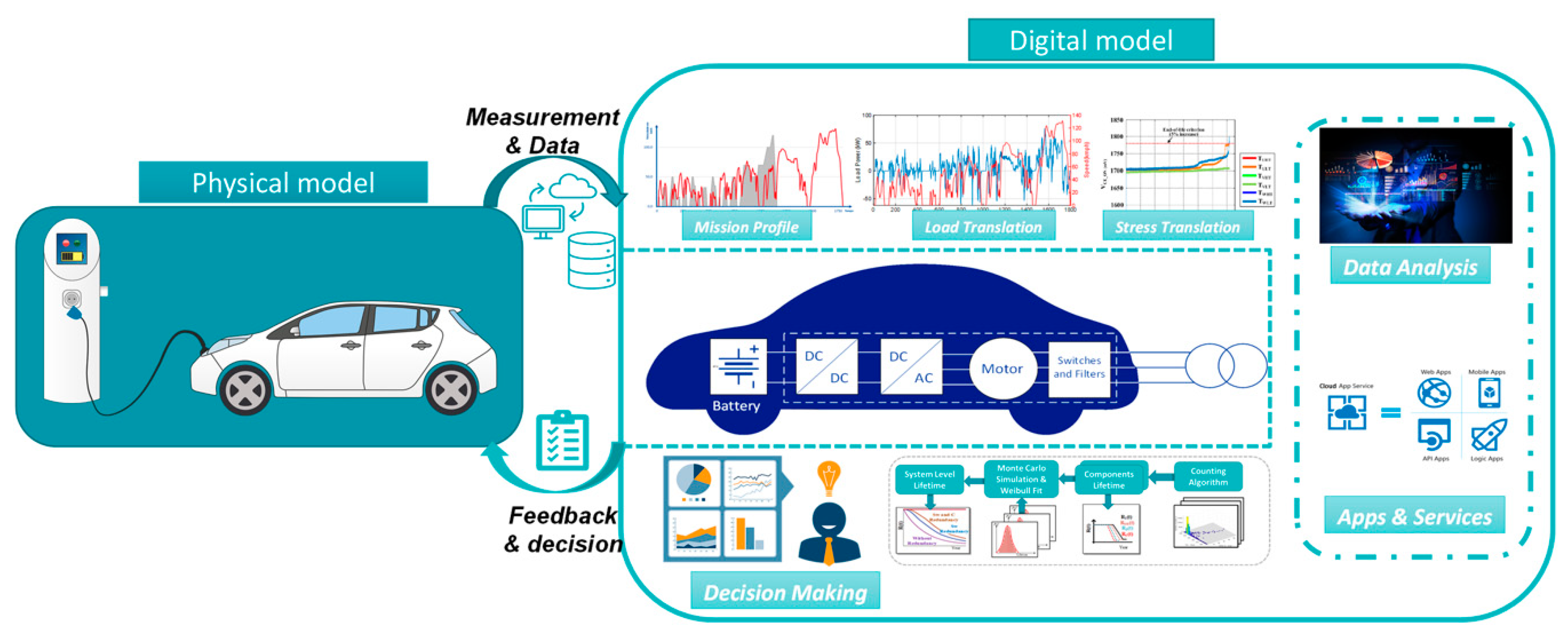
2.1. Digital Twin Development for EVs and Its Associated Benefits

For many years, automotive researchers and engineers have prepared analytical and simulation models of EV’s components and entire EVs, and over time, these models have become increasingly sophisticated and accurate. With the advancement of sensors, the Internet of Things (IoT) devices and network technologies, these offline physical assets convert into the digital models, are enabling smart system monitoring, prediction and re-scheduling of upcoming maintenance events, fault locations, fault endurance and remaining useful lifetime. The future EVs can provide a cost and effort reduction in the system design, verification, testing and time-to-market thanks to the EV digital twin. Five technology trends are developing in a complementary way to enable digital twins, namely, the IoT, cloud computing, APIs and open standards, artificial intelligence (AI) and digital reality technologies [22,23].
Figure 1 depicts the digital twin concept containing the real space’s physical device, which is a commercial EV drivetrain (e.g., battery, power electronics converters and motor) with sensors and control units. The virtual space contains the representative model in the simulation platform. It is a Multiphysics based high-fidelity model of the EV drivetrain. The transfer of data and information connects the real space with the virtual space. This reference model allows the vehicle designer to create a virtual process parallel to the physical one—this virtual process offers a tool for both static and dynamic analysis of the physical EV.
The digital twin model/tool of the EV can offer several benefits:
  • Ensuring a leap forward in user’s confidence, functionalities and energy efficiency of future EVs: These characteristics can estimate vehicle characteristics and usability. For example, affordability, driving range, range prediction, overall trip time and especially suitability of a long-range trip and comfort under all ambient conditions and traffic situations.
  • Multi-Physics Modelling for stress analysis: This analysis can prevent failures by predicting them in advance, which, in turn, will help to reduce the downtime.
  • Mission-profile-based reliability analysis for predictive maintenance: From the mission-profile-oriented accelerated lifetime testing, the degradation of the battery electric vehicle (BEV) drivetrain can be identified of the components critical to system reliability. Therefore, product developers will have more knowledge to be innovative in a fast and reliable way, testing many numbers and combinations of different variants of drivetrain components and experimenting with unorthodox approaches. Furthermore, using the data gathered from the vehicles’ digital twin can develop maintenance protocols/schedules to ensure that the components are available prior to their estimated failure in the EV and minimise inventory stockpiles.
Furthermore, one of the key future trends is to use the DT in the powertrain design, control design and reliability of advanced new powertrains. Thus, digital twin for design (DT4D), digital twin for control design (DT4CD) and digital twin for reliability (DT4R) are key new directions towards a more cost-effective and reliable future vehicle generations.

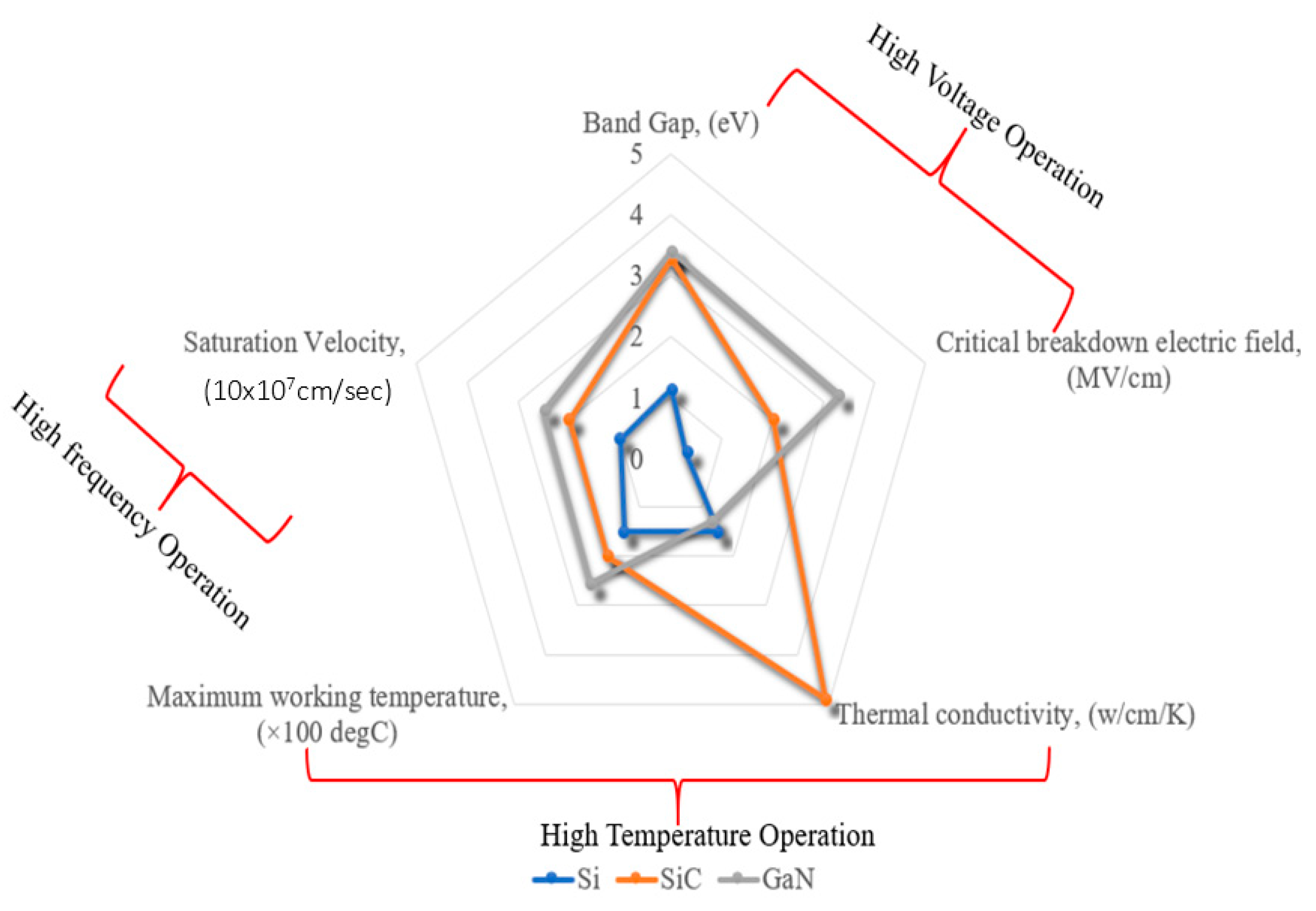
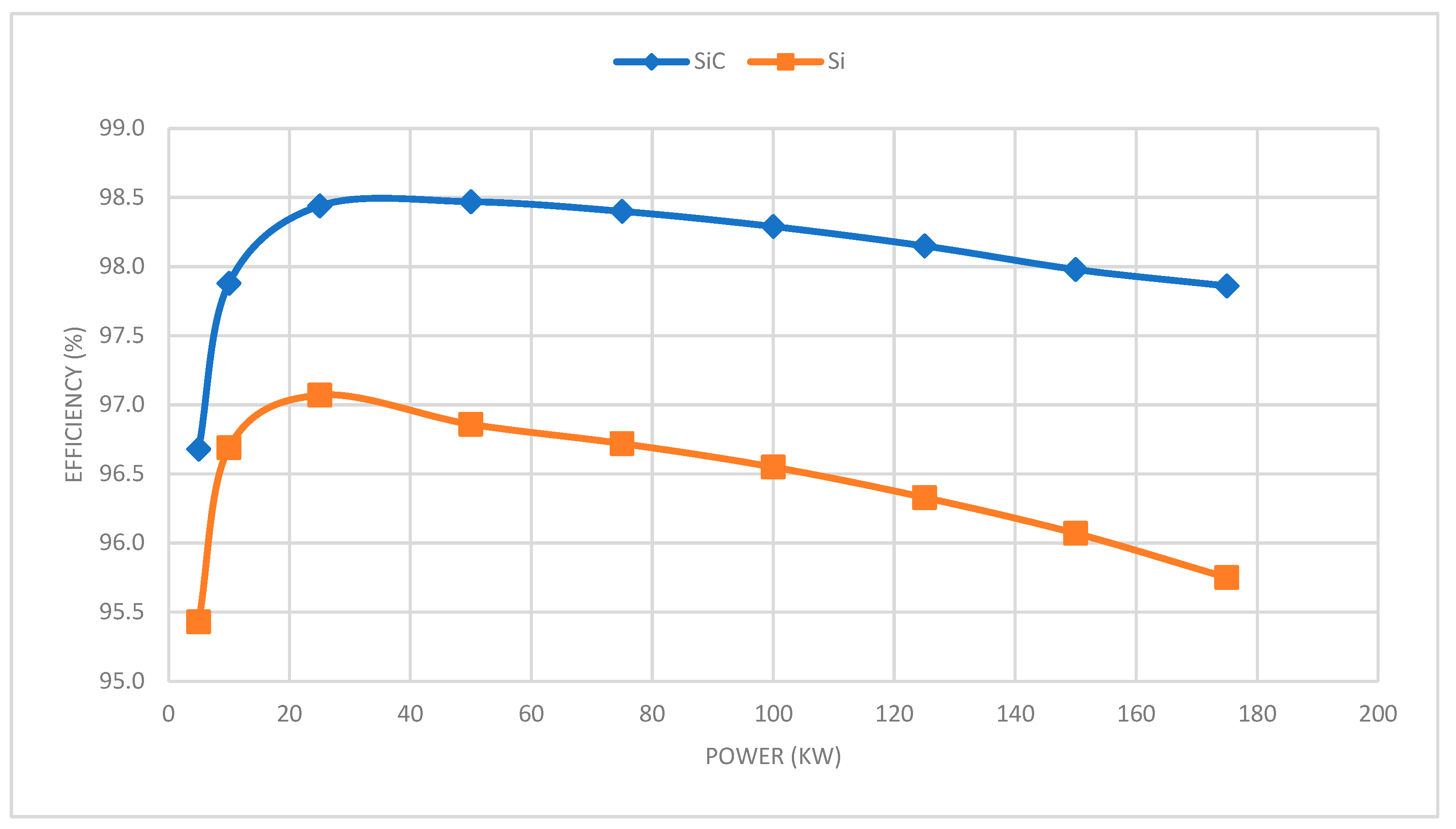
2.2. Power Electronics Interfaces Based on WBG Technologies

A key component in the EV propulsion systems is the power electronics converter [11]. The most important components of the power electronic converter (PEC) are the switches. It is self-evident that a lot of research is going on to the semiconductor materials, which are at the core of these switches. Nowadays, the switches inside the PECs are based on silicon (Si) semiconductor technology. However, new insights in switching technology have stimulated the development of wide bandgap (WBG) semiconductor materials, such as silicon carbide (SiC) and gallium nitride (GaN) [24,25,26,27].
The Si-based power electronics converters have a limitation in the switching frequency. In particular, the Si-based IGBT traction inverter has limited switching frequency up to 20 kHz and has been used typically under 10 kHz [28] in real implementations according to the user applications. Meanwhile, the Si-based on-board charger (OBC) has a restriction on the switching frequency to be less than 100 kHz for MOSFET-based OBCs [29].
However, the WBG semiconductors provide interesting characteristics and advanced material properties compared with traditional Si semiconductors, i.e., operating at higher voltages and lower leakage current, higher electron mobility, electron saturation velocity, higher switching frequency and higher thermal conductivity. The WBG materials require energy larger than 1 eV or 2 eV to transfer an electron from the highest energy level of the valence band to lowest energy level of the conduction band within the semiconductor [24,25,26,27,28,29,30]. A comparison of material properties between Si, SiC and GaN is shown in Figure 2.
Furthermore, the WBG semiconductors have high switching frequency capabilities, especially for low voltage applications enabling high efficiency and power density, as well as a weight reduction for power electronics interfaces and improving the whole energy efficiency of the electric powertrain.
However, there is a lack of technology maturity, design optimisation for fast development and control algorithms for the GaN-based power electronics converters when taking into account high switching frequencies (i.e., 40 kHz–100 kHz for inverter or active front-end systems and 200 kHz–500 kHz for the OBC systems) and allowing the operation at high temperature levels, as well as the expected cost. In addition, the multiphysics modelling and thermal management of these emerging GaN semiconductor devices have not been fully addressed in the literature. Thus, there is a strong need to develop such design optimisation and accurate models for the GaN-based power electronics converters with considering their parametric and non-parametric representations and to be used in the future as a digital twin.
Furthermore, in power electronic converters, semiconductor modules are the most failure-prone devices, due to high thermal stress. Most common failures of intrinsic types are time-dependent dielectric breakdown and electromigration [31].
Although technically the WBG-based power converter should be more reliable, due to their higher activation of energy, practically due to continuous improvement of cost-effective device packaging, the reliable operation of these compound semiconductors is not fully addressed. There are some research papers and industrial reports dealing with the reliability analysis of Si devices and recently, the SiC devices, whereas there are a few reports on the GaN power devices. Moreover, the GaN-based inverter is also a very new concept for the EV power electronics, but the voltage range is one of the key challenges in the next years. For the predictive maintenance and reliability study, the required stress-factor is also unavailable for the GaN technology, and there is a need for further investigation and focus on this research part in the near future.
In line with these WBG technologies, integrating the WBG power electronics interfaces either with electric motors or with the battery systems is one of the key future trends towards more efficient and smart cooling systems and thermal management concepts in vehicle powertrains.
More advantages of WBG technology are described in Section 4 about the charging infrastructure.

3. The Next Generation Solid-State Battery

Lithium batteries are the dominant type of battery technology in EVs. There exist many different types of lithium batteries with different characteristics [32,33,34,35]. The battery characteristics define their specific energy (hence, driving range), cycle life, power performance, safety, etc. Novel battery chemistries, composition and production steps can further improve vehicle’s driving range, environmental performance and cost [36].

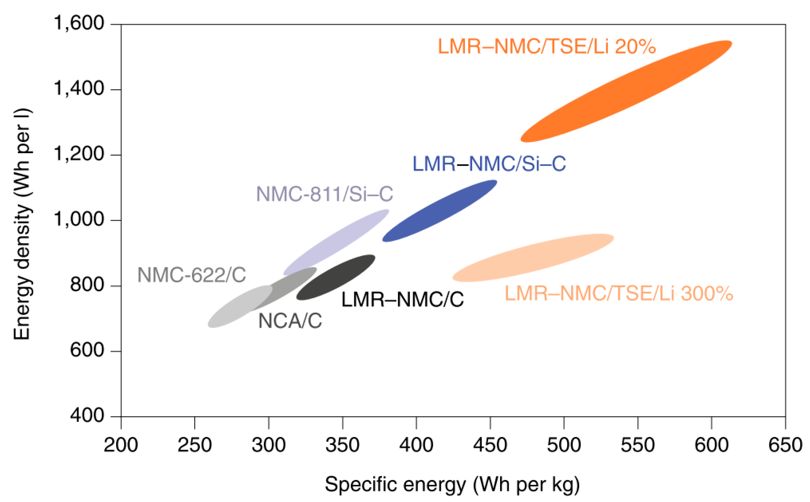
3.1. Recent Lithium Battery Technology Developments

Li-ion batteries are often classified according to the cathode material used [37,38]. Among them, LCO (lithium cobalt oxide) is the most mature technology, with the highest volumetric energy density, but low power density and service life. While this remains the technology of choice for consumer electronics, much of the market is moving away from this technology, due to its reliance on cobalt, a scarce resource commonly mined in developing countries.
On the other hand, LFP (lithium iron phosphate) batteries are made from the ubiquitous iron and phosphate. They have a very long life and can deliver very high power thanks to the rigid olivine structure of the material. Unfortunately, this technology is less suitable for high energy applications, due to the inherent low potential vs Li+ and specific capacitance. LFP remains a strong choice in power applications (hybrid vehicles, power tools) or where many cycles are required (commercial electric vehicles, grid energy storage).
Both NCA (lithium nickel cobalt aluminium oxide) and NMC (lithium nickel manganese cobalt oxide) are technologies with a high energy density, which means that they are commonly used in electric cars. A clear trend in both technologies is to reduce the amount of cobalt in favour of the amount of nickel. This ensures a higher energy density and reduces the dependence on the precious cobalt. NMC has been commercialised in different types depending on the stoichiometric ratio of the elements. For example, NMC111, where the three elements are each present in the same amount, NMC532 and NMC622. Given the lower amount of nickel in favour of more manganese, NMC111 is more suitable for higher power applications, while NCA, NMC-532 and NMC-622 can be considered as state-of-the-art cathode materials (see Figure 3).
The commercially available material choices for the negative electrode are more limited. Carbon-based anodes (amorphous carbon and graphite) have dominated since the commercialisation of the Li-ion battery in 1991, due to their low potential vs Li + and good specific capacitance. While graphite was found in 91% of commercial batteries in 2016, only 7% used amorphous carbon and 2% LTO (lithium titanate oxide). Although the latter charges the batteries extremely quickly for a large number of cycles, the raw materials are very expensive, and they have a low energy density [39].
Thanks to the extensive research and development of Li-ion batteries in recent years, we are gradually reaching the maximum potential of today’s electrode materials. To further increase the energy density, a switch to new materials is inevitable (see Figure 3). Silicium will play a crucial role in this in the near future. With a theoretical capacity that is nearly 10 times higher than graphite and a low cost, silicon is an excellent candidate for next-generation anode materials [40]. Although the lifespan of pure silicon batteries is still very limited, the element is already added to the graphite electrode in small quantities (e.g., 5% in the Panasonic cells of the Tesla X). As technology advances, the percentage of silicon in the anode will increase further over the next five years, while the amount of nickel in the cathode will increase further. This will lead to a gradual increase in energy density. A major leap in energy density is not expected until 2025, when post-Li-ion technologies, such as lithium-sulphur, lithium-oxygen, lithium metal and solid-state batteries are expected [41].

3.2. Towards Solid-State Batteries

The next generation of Li-ion battery technology, set to enter the market in the coming five to ten years, is likely to have low nickel and cobalt content. Near-term developments should enable cell-level energy densities of up to 325 Wh/kg, and pack-level energy densities could reach 275 Wh/kg [42].
To meet these targets, solid electrolytes are extensively studied. They are non-toxic and not flammable. Accordingly, a significant improvement in safety could be observed. The voltage losses, due to concentration polarisation, occurring in liquid electrolytes at high power applications is eliminated in solid electrolytes allowing them to use thicker electrolytes high energy density values. It’s also worth to mention that solid electrolytes show outstanding resistance on dendrite propagation which enables using the advantages of Li metal as an anode [43].
The solid electrolytes developed for EV applications require fast charging properties. The highest current density above which the battery will be short-circuited, due to Lithium dendrite penetration (known as critical current density) is one of the important parameters determining the fast-charging capabilities. State-of-the-art critical current density values around 0.1 mA/cm2 is quite far away from the target value (5 mA/cm2) [44,45]. Besides, there is a difference between critical current densities during charging and discharging. Today, critical current densities during charging are found to be higher than during discharging [43].
To reach the high specific energy with an improved cycle life in solid-state batteries, it’s crucial to assess the electrode-electrolyte interfaces. Electrochemical interfacial instability is one leg of the cell failure. Even though, the solid-state electrolytes have currently a wide electrochemical stability window up to 6 V (vs. Li+/Li) in which almost all of the battery materials stay stable; the solid electrolyte-solid electrode contact could be lost at some point resulting in an increase of the cell impedance. Some methodologies like liquid-solid hybrid electrolytes were proposed for the purpose of clarifying the interface instabilities [46].
Based on their confirmed applications in the field of energy storage, polymer and polymer composite electrolytes are becoming a focal point of solid-state batteries. They exhibit reduced flammability compared to liquid electrolytes and outstanding mechanical flexibility, processability and scaling-up. An ion conductive polymer, poly (ethylene oxide) (PEO), and its derivatives are promising candidates for solid-state batteries in terms of their ionic conductivity ranges. However, ion conduction is still poor and more complex compared to the traditional organic liquid electrolytes [47,48].
Assembly of solid-state batteries is quite similar to the conventional Li-ion batteries involving separate lines for anode, cathode and electrolyte sheets. However, the difference lies in the manufacturing of battery components and the assembly order. Unlike traditional Li-ion batteries, electrolyte should be formed first, and electrodes should be attached afterwards. Additionally, the synthesis of solid electrolytes requires relatively high temperatures (above 1000 °C in case of Li7La3Zr2O12) and generate highly toxic H2S (in case of sulphides like Li6PS5Cl) [49].

3.3. Challenges and Potential Solutions for the Solid-State Battery

Energy and price targets for EV applications in both cell and pack level are quite ambitious for short-term expectations. However, there is an extensive dedication to this purpose even if the expected safety level is sacrificed. Some of the challenges that scientists are currently trying to overcome are listed below:
  • Poor wetting between Li and solid electrolyte: The poor wetting between lithium and solid electrolyte results in an interfacial resistance. Solid electrolytes, especially ceramic-based solid electrolytes, have relatively high interfacial resistance caused by poor wetting of Li. This inhibits the utilisation of Li in solid-state batteries. It was found out that polymer-based solid electrolytes, despite their lower ionic conductivity when compared to ceramic counterparts, shows enhanced Li wetting. Accordingly, Li wetting problem can be solved by using polymer/ceramic composites as electrolytes [43].
  • Dendrite propagation and growth: When using Li metal, dendrite formation and propagation become serious problems in high power applications. Critical current density values for solid-state batteries are quite far away from the target value of 5 mA/cm2 [44,45]. Besides, there is a difference between plating (charging) and stripping (discharging), and the critical current density needs to be eliminated. The mechanism and possible solutions for that are still unclear, but special attention has been paid on producing the electrolytes as dense as possible, since the dendrite propagation is drastically inhibited in dense microstructures [43].
  • Solid electrolyte synthesis: Solid electrolytes having high ionic conductivity is hard for synthesising, storing and handling. They require sophisticated methods, oxygen-free environments that make their use not cost-efficient. In this regard, there’s an ongoing desire to reduce the production cost and ease the handleability of the solid electrolytes.
  • Cell fabrication: Cell fabrication by using a ceramic type of electrolytes require hot pressing techniques that apply high pressure and temperature at the same time to ensure the smooth contact between electrolyte and electrodes (Figure 4). However, that problem can be solved by design engineering. Bulk type solid-state batteries can be assembled, and satisfying capacity retention could be gathered from these batteries [50]. On the other hand, scalability is the most important challenge for bulk-type battery designs. Polymers and polymer/ceramic composites are considered as a potential solution for large scale manufacturing of solid-state batteries because of their industrial-scale ease of production.
In addition to all these, Li metal creep at high operation temperatures can sometimes occur. The up-to-date solution to prevent this is improving creep behaviour of lithium by alloying [52].

3.4. Self-Healing Batteries with Embedded Sensors

Battery performance varies greatly over time. This can be attributed to several unwanted side reactions that occur at the material level, which ultimately induce capacity fade and impedance growth which can lead to potential safety hazards in the form of dendrite short circuits. As such, it is extremely important to monitor and control batteries accurately during their operation. This is conventionally achieved by implementing a Battery Management System (BMS). The BMS ensures that the voltage, current and temperature of each cell stays within its optimal safety boundaries. Additionally, the BMS uses the measurements on voltage, current and temperature to determine the battery states, such as: State of charge, which shows how much energy is left in the battery [53], and the state of health, which shows how much energy the battery can still hold compared to when it was new [54]. These important battery states cannot be measured directly and must be estimated using complex algorithms and battery models.
However, most of these activities rely on the use of sensors outside rather than inside the battery cells, limiting the knowledge to macroscopic properties, but overlooking internal chemical and physical parameters of prime importance for monitoring battery lifetime. Because of this, implantable sensors which are integrated within the battery cell are increasingly attracting interest. This will allow us to measure unexplored quantities, gain a deeper knowledge of the physical parameters, and understanding the parasitic chemical processes within the cells. This will drastically enhance battery reliability and safety. Parameters, such as temperature, pressure, strain, expansion and electrolyte composition, are among the valuable options [55]. Besides offering fundamental insights to battery operation, smart sensors would also develop a next-generation of state estimators and BMS.
Self-healing batteries is another new field of research. Battery degradation is the result of unwanted chemical changes within the cell. The concept of self-healing in batteries is to reverse these changes to restore the battery to its original configuration and functionality. Specifically, self-healing functionalities in batteries will target:
  • Auto-repair of damaged electrodes to restore their conductivity.
  • Regulation of ion transport within the cell.
  • Minimising the effect of parasitic side reactions.
The introduction of self-healing mechanisms to the field of battery technology has been slow, due to the challenging chemical environment they must operate in, but the topic is now rapidly gaining momentum.
Recently several self-healing concepts have been discussed in the literature, such as: The self-healing polymer substrates which allow to repair damaged electrodes and restore their conductivity [56]. Self-healing polymer binders, which prevent the loss of electrical contact between cracked active material particles, for example, in silicon anodes [57]. Another promising concept is functionalised membranes which can trap unwanted molecules and prevent them from reacting with other materials in the cell. Self-healing electrolytes, on the other hand, contain healing agents which are capable of dissolving unwanted depositions [47]. Finally, a promising future concept is the encapsulated self-healing molecules. These consist of healing agents contained in microcapsules. When needed, the healing agents can be released by providing the right stimulus.
It should be noted that sensing and self-healing functionalities are intimately linked. Smart batteries integrate both these functions: Signals from the integrated sensors will be sent to the BMS and analysed. If problems are detected, the BMS will send a signal to the actuator, triggering the stimulus of the appropriate self-healing process. This game-changing approach will maximise reliability, lifetime, user confidence and safety of the batteries of the future.

3.5. Second-Life: Challenges and Opportunities

A battery is considered at the end of its life when its state of health is below 80%. Therefore, a battery at the end of its first life can still be used in another (or the same) application to fit in the 4R-End of Life (EoL) management strategies: Reuse, Repair, Remanufacture and Recycle. Today, the life of a battery looks like that: It is manufactured, used in a vehicle, dismantled and partly recycled. However, it can be refurbished to be used in stationary applications or in automotive applications.
In Europe, a study from the JRC showed that in 2025 between 0.6 GWh and 2.4 GWh batteries could be available for second use [58]. Additionally, the global storage market is more than 10 GWh today, according to the International Energy Agency.
However, to introduce second-life batteries in the market, there is a need to overcome certain challenges. Evaluating the potential of a battery at the end of its first life raise the needs for State of Health estimation techniques and the development of more further lifetime predictive models [59]. There is also a need for safety protocols for the testing, dismantling, remanufacturing and use of these batteries. Machine learning algorithms, for instance can help to address these challenges [60]. Finally, the legal framework can also be an obstacle. In the actual European battery waste directive from 2006, second-life is not explicitly mentioned. However, the new version will define the legal framework for second-life with the definition of waste battery and producer responsibility.

4. Intelligent Bidirectional V2G and/or Ultra-High-Power Charging Systems

4.1. Introduction to Unidirectional and Bidirectional Charging Systems

The fast and efficient charging of the EV battery is important for the large-scale deployment of EVs. Today’s electric vehicle can travel 300–400 km without the need to charge. There are many challenges to consider: One is the availability of charging stations everywhere; second is fast charging; and another one is the enhancement of power density and specific power [61].
Nowadays, four main types of charging exist. Following types of the charger are explained in Table 1 [62].
The level-1 and level-2 chargers are used as on-board converters to charge the batteries. Level-3 chargers typically work as an external converter and can effectively manage the flow of high power. Mostly, slow charging takes place overnight, and it is associated to the level-1 and level-2 charging. The level-1 and 2 are a basic method of charging, typically situated at home, public and private facilities. A level-3 high power DC fast charger is often located at commercial places like hotels, shopping malls and in the parking areas, etc. [61,62].
The typical level-2 charger provides up to 22 kW AC charging, and charges the battery in 120 min and delivers energy for travelling 200 km. The charging time will be reduced to 16 min for 200 km by 150 kW DC charging stations. At 350 kW charging station, the charging time would be close to the time of gas refuelling: around 7 min [63,64]. However, it should be noted that the charging time also relies on the battery of the vehicle.
The three-phase front-end converter topology includes a diode rectifier, an active buck/boost rectifier, a matrix rectifier or a Vienna rectifier [65]. The simplest and cost-effective approach for power conversion is a diode rectifier. However, the output fixed voltage is dependent on the three-phase supply voltage. The disadvantage of this approach is the unfavourable total harmonic distortion (THD). A three-phase active front-end (AFE) rectifier tackles the issue of THD by generating three-phase sine shaped input current waveforms with improved power factor and efficiency and offering variable DC output voltage. A Vienna rectifier is increasingly popular; possibly it is less well established. Among all mentioned three-phase conversion techniques, the AFE boost rectifier can be used for off-board fast-charging systems [63,66].
Grid-connected power electronic converters (PEC) are more widespread than ever, due to the rise of battery electric vehicles. If these PECs are bidirectional, the power stored in a vehicle can be used to supply peak power (vehicle-to-grid, V2G), or as temporary storage for excess electricity (grid-to-vehicle, G2V). To accommodate the bidirectional flow of power, existing PEC topologies have been re-adapted to use active switches instead of diodes.
The system architecture of a multiphases-bidirectional on-board charger is illustrated in Figure 5.

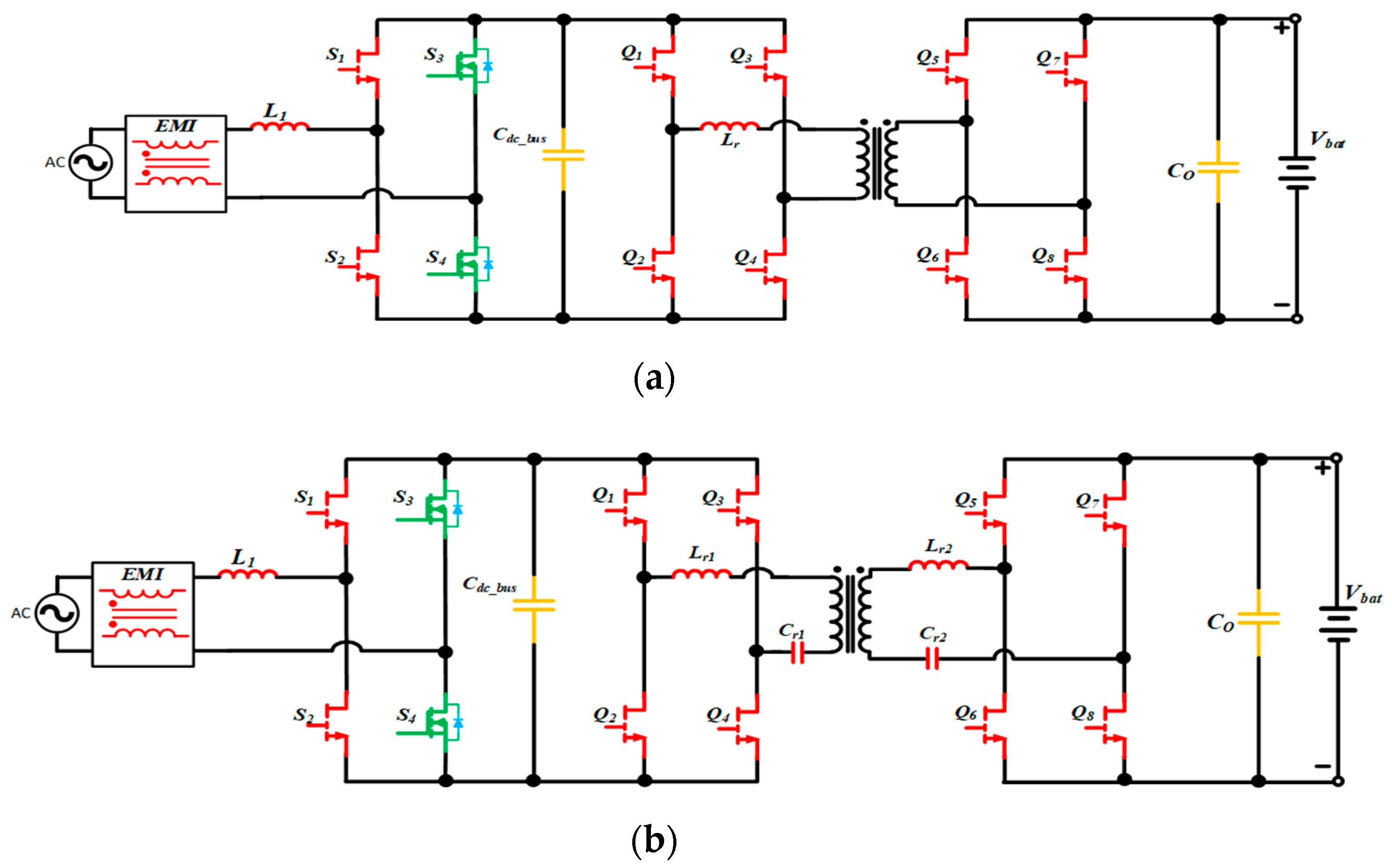
4.2. Wide Bandgap Devices for Bidirectional (V2G/G2V) On-Board Charging Systems

It is essential to consider several elements in developing the PEC for the off-board charger, i.e., high efficiency, high power factor, cost-effectiveness, smaller system size and weight, distortion-free operation with limited grid impact and high reliability.
To meet the demand for a lightweight, compact and efficient OBC, wide bandgap (WBG) devices will be also for the charger a promising technology. The GaN power transistors, which have extremely low-gate charge and output capacitance, can be switched at high frequency. This allows minimising the size and weight of passive components, such as inductors, capacitors and transformers [67,68]. To explore further potentials of using GaN power transistors in OBCs, semiconductor manufacturers recently have introduced many new GaN high-electron-mobility transistor (GaN-HEMT) devices with a high voltage rating of 600 V or 650 V and current rating from 20 A to 60 A [64,67]. These GaN-HEMT devices could be suitable for OBCs with power levels from 3.3 kW to 22 kW.
Figure 6 shows two single-phase bidirectional OBC structures, which adopt the same totem pole PFC for the AC-DC stage and different topologies in the DC-DC stage. As shown in Figure 6a, Dual Active Bridge is a promising topology thanks to galvanic isolation and bidirectional power conversion with zero voltage switching (ZVS) for both primary and secondary sides, the small size of passive components and fixed-frequency operation [69]. However, the full range of ZVS becomes hard to achieve, due to the wide range of the load power. The resonant bidirectional CLLC topology (C is capacitance and L is inductance), as shown in Figure 6b, exhibits high efficiency, due to the ZVS in the primary bridge and zero current switching (ZCS) in the secondary side. The drawback of CLLC topology in the charging application is that the switching frequency needs to deviate from the series resonant frequency for output voltage regulation. To overcome this issue, regulating the DC bus voltage in the PFC stage instead of frequency modulation in the DC-DC stage is proposed in Reference [70] so that the resonant CLLC stage can operate at its optimal efficiency point [69,70].

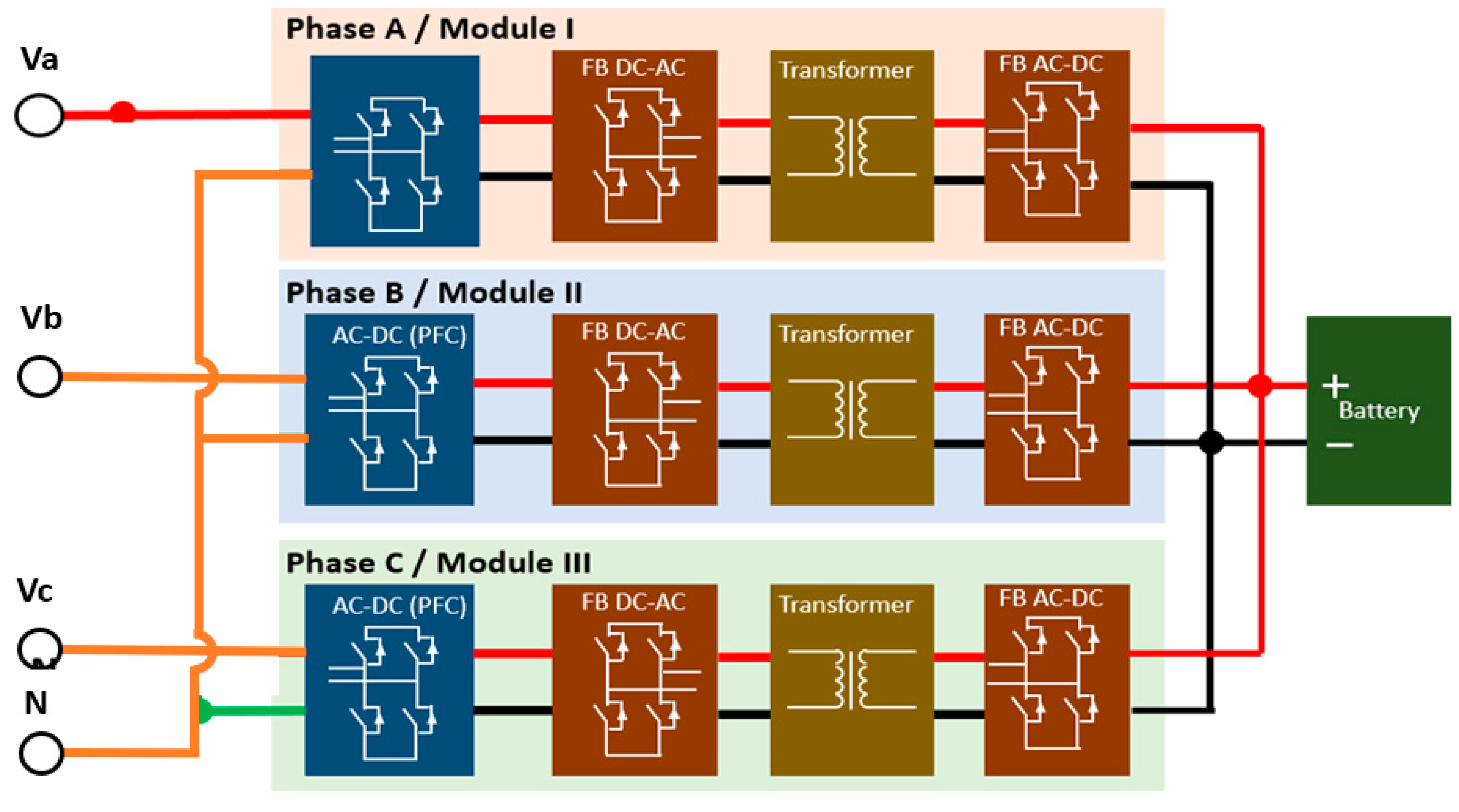
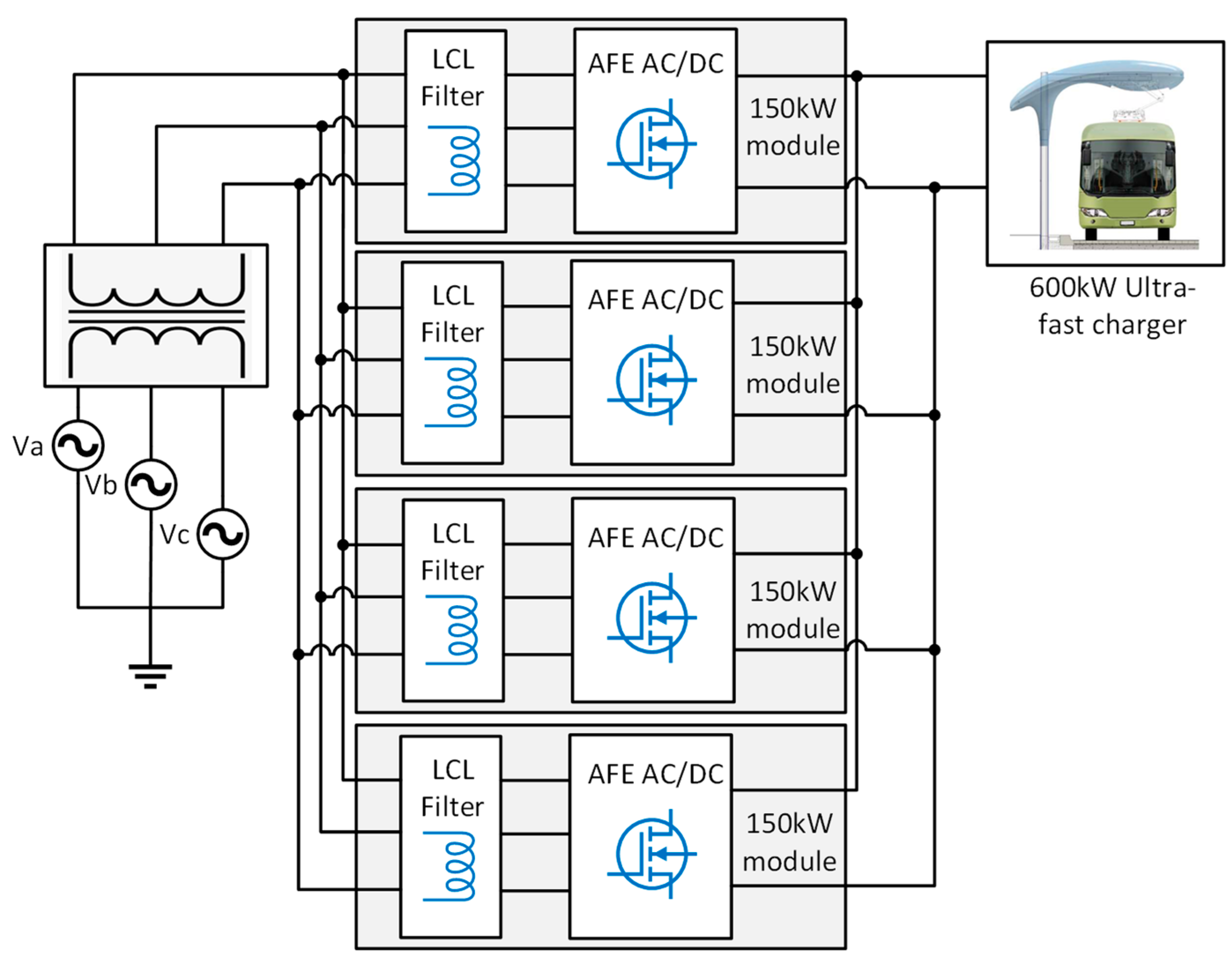
4.3. Ultra-High Power Off-Board Charging System

For design and development of ultra-fast charging systems, a modular converter approach is an appropriate solution. Hence, the current topology, which is proposed for the 600 kW DC ultra-fast charger, is realised by merging four AFE converters with each other in a parallel configuration, as shown in Figure 7 [71].
A comparative analysis has been performed between silicon and silicon carbide-based semiconductors for each module at a power rating of 150 kW. The efficiency comparison between Si (SKM400GB12T4) and SiC (CAS300M12BM2) devices, is based on a non-linear electro-thermal simulation model at different power levels. For both cases, the related datasheet data are inserted in simulation. Figure 8 shows how much the SiC devices are more efficient than silicon for a charger. This means that the loss in Si is higher than SiC, hence energy can be saved by using wide bandgap devices.

4.4. Intelligent Bidirectional Control Systems

PECs with bidirectional capabilities enable the use of advanced V2G and G2V control strategies. Using a PQ theory-based control, the system can guarantee a unity power factor while charging the EV battery, and an accurate reactive power reference tracking in V2G mode [72].
Using parallel power converter modules is a low-cost option to improve the overall versatility, efficiency, reliability and grid impact of the system [73,74]. However, it will result in more complex control architectures.

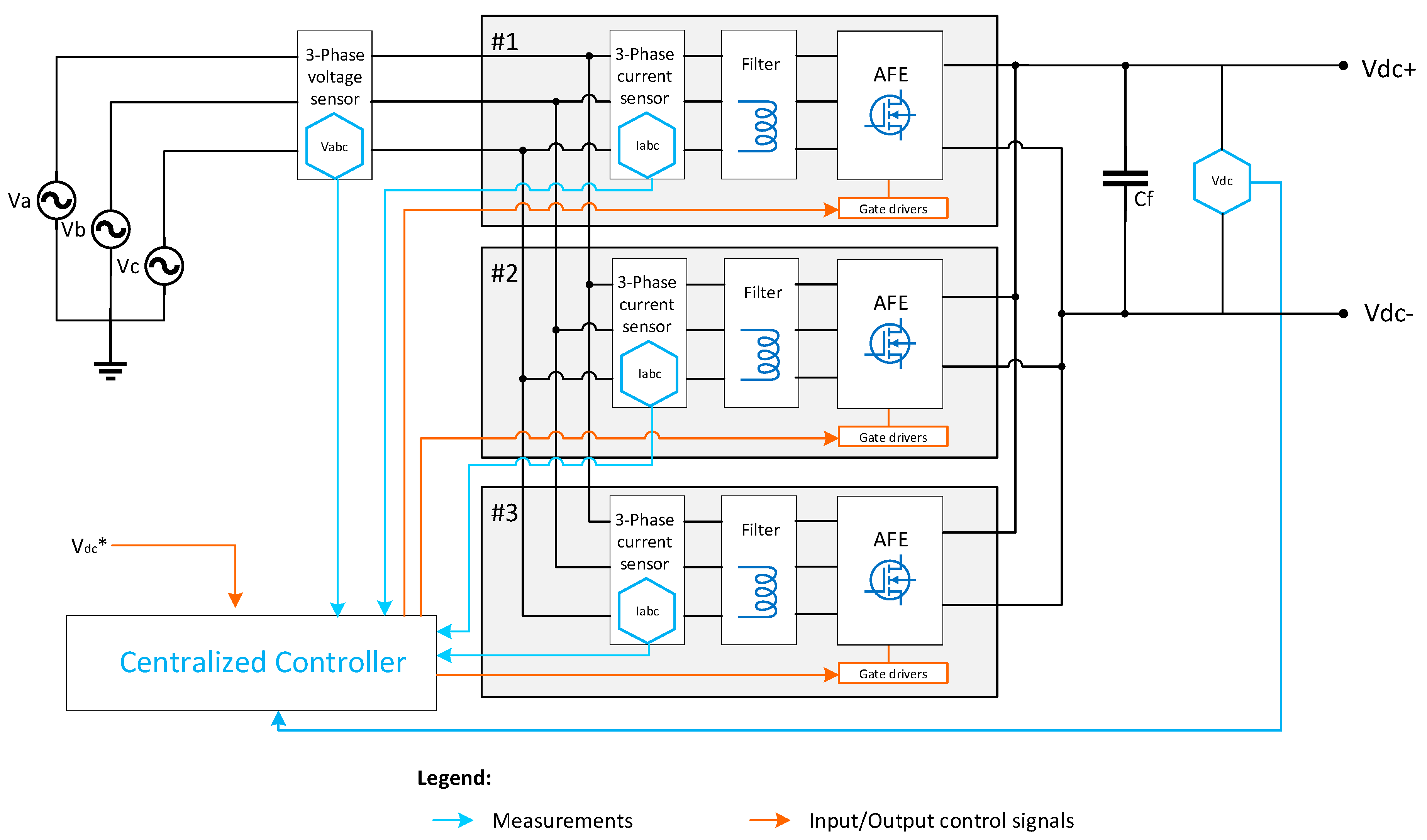
4.4.1. Centralised Control Systems for Modular PEC

The simplest way to control the parallel converters is to use a single controller. Figure 9 demonstrates the centralised control system for modular Active Front-End rectifiers [71]. However, this mode of control can also be used for other bidirectional parallel converters employed in the V2G/G2V systems, such as DC-DC converters, single phase power factor correction rectifiers, etc. In this setup, the controller is connected to all sensors and generates all gate signals. The advantages of such a system are the simple implementation of current sharing, the interleaving, the minimum additional sensors and the absence of synchronisation issues. The disadvantage of such a system is that it has a single point of failure—the central controller and shared sensors.

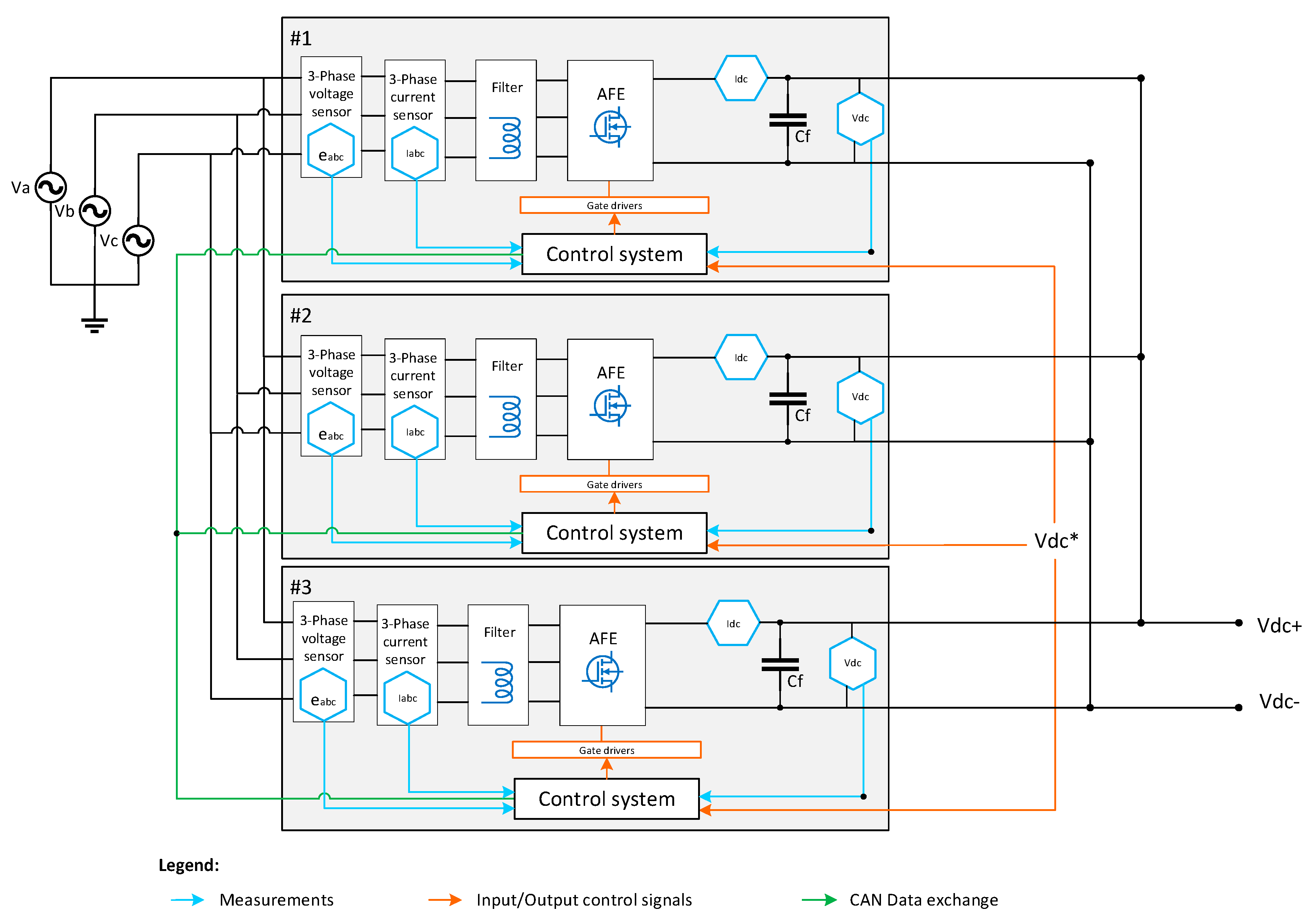
4.4.2. Distributed Control Systems for Modular PEC

An alternative to a centralised control system is a distributed control system, where each power module has a separate control module. One example of a parallel PEC system with the distributed control system is shown in Figure 10 [71]. Based on the relationship of these control units between each other, there are several types of distributed control systems that will be discussed in the following paragraphs.
(A) Master-Slave Control Systems for Modular PEC
The first distributed control strategy to consider for modular PEC is a master-slave control, where the outer loop is implemented in the master controller, and the output of this loop is shared with slave modules via a data bus. This system also has a single point of failure—the master module, hence “auto master-slave” systems have been introduced: In the case of the master module’s failure, one of the slaves can take its place [75,76]. Another challenge of master-slave systems, both conventional and “auto”, is stability. An article from 2016 [77] demonstrates how delays in the CAN bus can affect the stability of the system with master-slave control. Moreover, the delay induced by the data bus increases with the number of parallel modules [78].
(B) Masterless Control Systems for Modular PEC
Another distributed control system to be considered for parallel modular PEC is the masterless control technique, which was described in Reference [79] for the control of parallel DC-DC converters. In this system, all modules are equal, they exchange data through CAN bus, but they use their own current reference for the inner current loop, and therefore, expected to be more resistant to instabilities imposed by the data bus delay. In this setup, each module has its own controller and sensors. Each controller can act standalone, or work as a part of a system. The advantages of such a system are increased scalability, reliability and stability. Moreover, masterless control introduces a number of additional functions, such as: Dynamic resource allocation, automatic interleaving and measurement error compensation.

5. The road to Climate Neutral Transport and Energy Sector

5.1. Sustainable Energy Communities

The bidirectional chargers described in the previous section will play a crucial role in integrating renewable energy sources, such as wind, sun and hydro, into sustainable energy communities. Renewable energy sources are seen as reliable alternatives to the traditional energy sources, such as oil, natural gas, or coal [80], and have a much lower impact on climate change from a life cycle perspective even when considering hourly consequences of intermittency of renewables in a full dynamic energy system [81]. Due to the increasing number of distributed power generation systems connected to the utility network, challenges are raised concerning the power quality, safe running and islanding protection. As a consequence, the control of distributed generation systems should be improved to meet the requirements for grid interconnection [80].
If the whole vehicle fleet becomes electric, this would only mean an additional demand for electricity of 20% (example of Belgium) [82]. The introduction of renewable energy sources is gearing up. But what if there is no wind and sun? At these moments, we either need to rely on other sources, or we need to invest more in energy storage. The battery of an electric vehicle can play an important role. When there is an excess of wind or solar electricity, it can be stored in the batteries of cars. It is defined as smart charging management. When the demand for electricity is high, the stored electricity can be given back to the grid. This is what has been called V2G or ‘vehicle-to-grid’. A thorough cycle test of the battery ageing effects of using the V2H to power a house has shown limited impact. This is mainly explained by the limited and optimising discharge current to power a house, which is much lower compared to the current needed to accelerate a vehicle, resulting in non-significant battery ageing effects of the V2G features [83].
Inside a Local Energy Community (LEC) there are different valuable ways to integrate a battery:
  • Batteries can be used for energy arbitrage: for economic benefits, energy is stored when cheap in the wholesale market, and released when more expensive.
  • Batteries can help in delaying or reducing investment needs in production, transmission or distribution infrastructure, this service is called capacity credit. This can be done by load levelling or peak shaving for instance.
  • The fast response of batteries is necessary to provide high performance ancillary services such as voltage and frequency regulation.
  • Behind the meter, batteries can help in reducing electricity bill, increasing of PV self-consumption in microgrids and backup power.
It is foreseen that the electricity grid will evolve towards more decentralised production and the emergence of energy communities. Bidirectional charging systems of the electric fleet are an essential element in the energy management of such systems and can provide flexibility services, increase self-consumption and sustain in avoiding grid congestion. A techno-economic assessment of a vehicle-to-grid case study can be found in Reference [84].
However, to develop bidirectional functionalities, both vehicles and chargers must be capable of variable and bidirectional power transmission and require intelligence and communication with the local grid operator, features that require further research. First insight shows that integrating electric vehicles smartly in a grid can help to capture the grid balancing value streams [85].
Moreover, the user acceptance and business models regarding these functionalities are largely unknown, untested and uncertain in the already heavily scrutinised market of electric vehicles. Electric vehicles, as part of the solution for supply–demand balancing in local energy systems with several energy vectors, need to be further tested and validated in real-life circumstances. Forecasting of parking behaviour and mobility needs play an essential role, and its development should be based on monitoring daily use of all kinds of travellers. The deployment of a living lab where such experiments can be are carried out is, hence, of primordial importance. Different concepts and specific requirements on integrating the V2G in a local energy system are described in Reference [86].
A possible solution and opportunity are to change the traditional energy system into Local Energy systems (LES) managed by a Local Energy Community (LEC). The challenge is to correctly energetically balance and financially optimise such a complex system with multiple connected, decentral devices that need to be controlled to guarantee the overall quality and safety. Total system optimisation is achievable only if various other types of energy vectors (electric, thermal, HVAC, mobility, data, etc.) are managed together from a macro perspective. At the VUB, in close collaboration with the Green Energy Park, a 20 MW living lab is being set up for industrial collaboration (more info: www.greenenergypark.be (accessed on 3 February 2021)). In this living lab, the VUB deeply researches the management, control and exploitation of a CO2-neutral, self-sufficient multi-energy microgrid. A first, promising calculation of minimising the levelised cost of energy of the microgrid living lab can be found in Reference [87]. This paper [87] makes a techno-economic assessment of the energy management that will be part of the living lab microgrid placed in Zellik, Belgium. A levelised cost of energy (LCOE) calculation approach is proposed that incorporates a hybrid energy generation plant composed of solar and energy generation and a lithium-ion battery. The LCOE evaluated nine battery operation scenarios to determine the most profitable battery operation criterion.
The living lab interconnects various prosumers: A large datacentre, an incubator for start-ups, a large parking lot (150–400 vehicles) with electric charging infrastructure and 70 companies from different sectors. In addition, the CO2-neutral microgrid will integrate renewable energy production systems (3–4 MW solar, 3–4 MW Wind Energy), cogeneration (or Combined Heat Power CHP) and energy storage capacity.

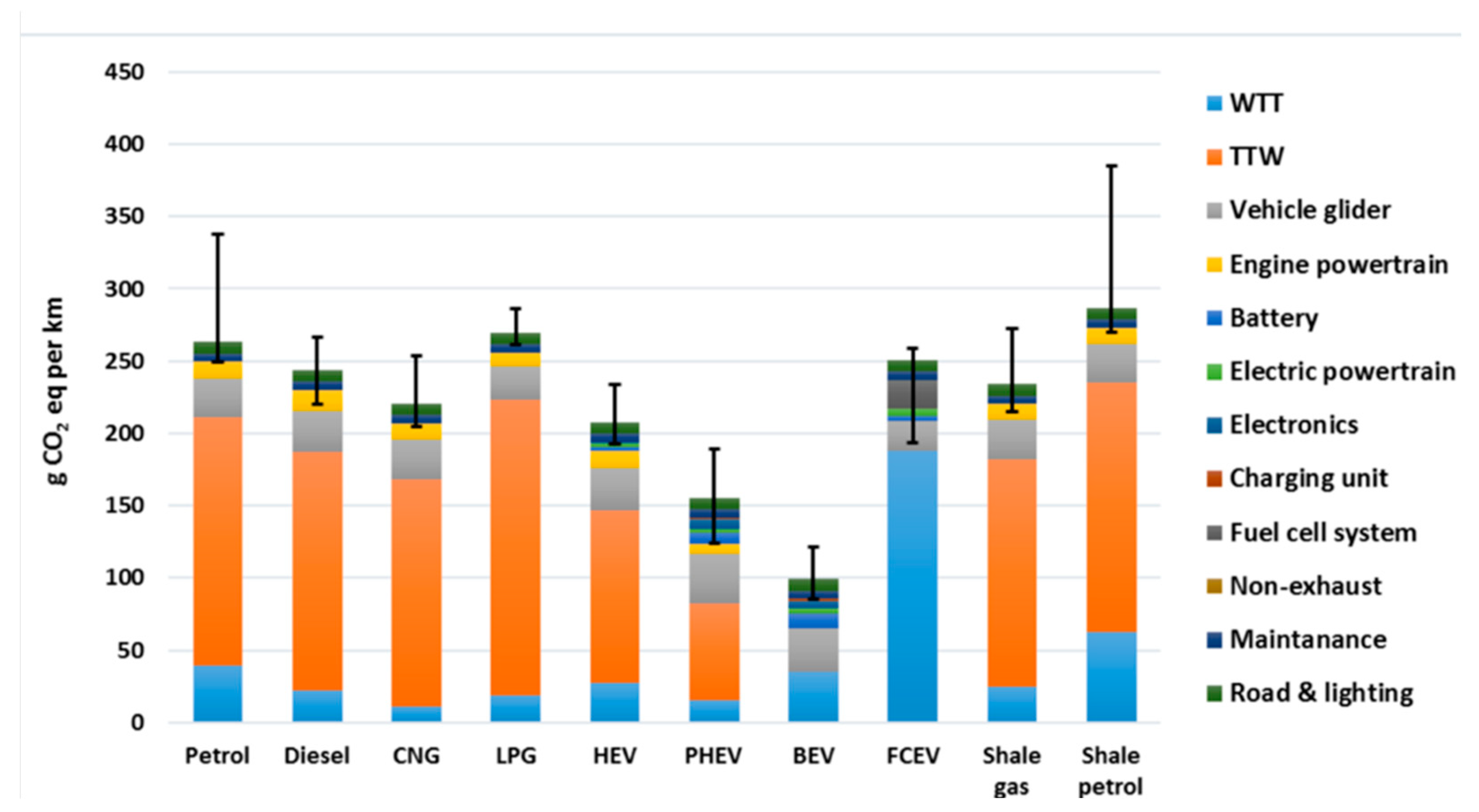
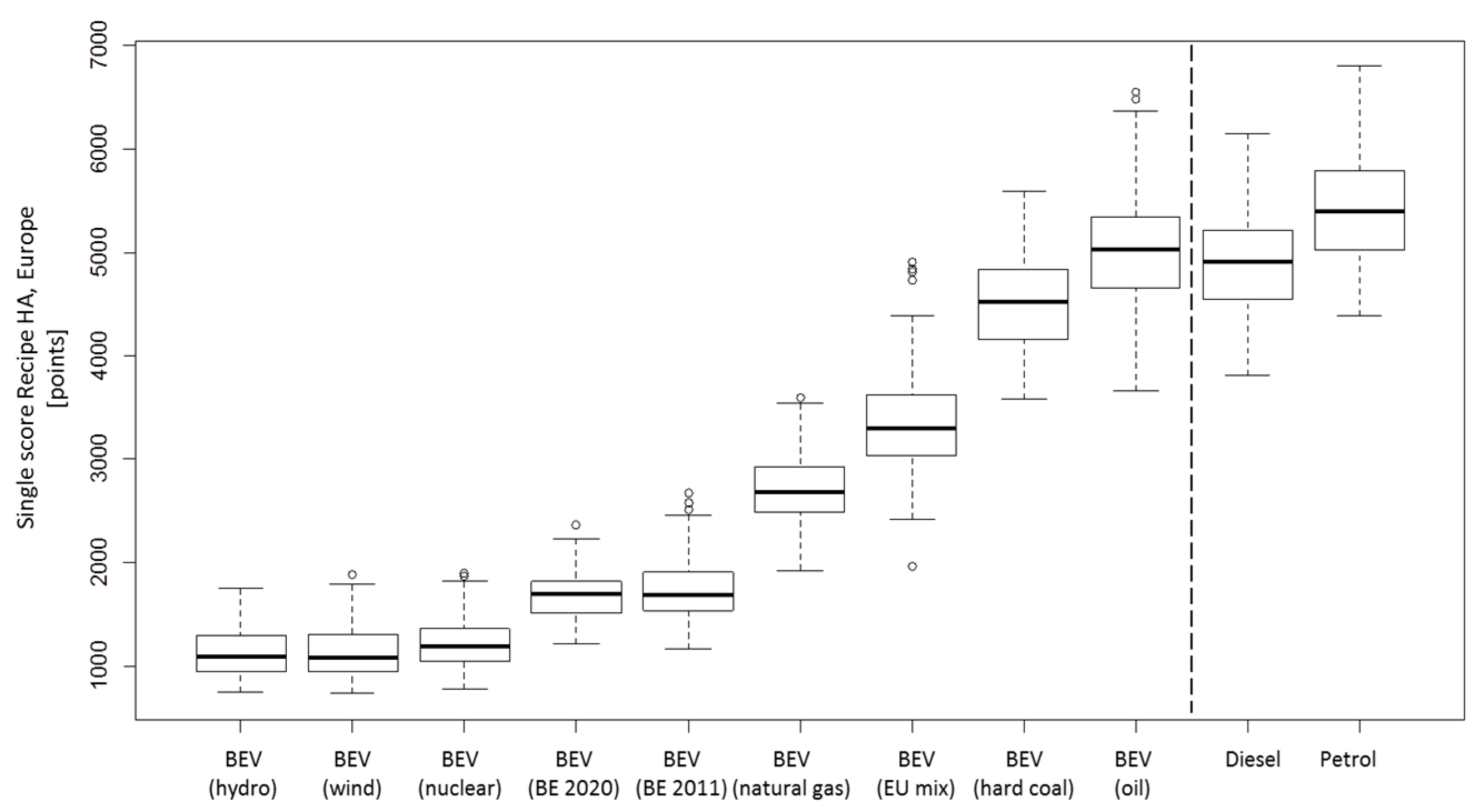
5.2. Current Impact on Climate Change

The above-mentioned increase in renewable energy sources will have an impact on the EV’s impact on the environment. In a full life cycle, electric vehicles emit two times less carbon dioxide (CO2) than petrol or diesel engines if we take the European electricity mix. This can be even four times less if we take, for example, the Belgian electricity mix. If cars were driving on renewable electricity, carbon dioxide emissions could be further reduced by more than 10 times [8,82,88].
Figure 11 shows the results for climate change or global warming potential for all the compared vehicles. Overall, the BEV charged with the Belgian electricity mix has the lowest climate change score. This is because, first, there are no tailpipe emissions, and secondly, the Well-to-Tank (WTT) emissions of Belgian electricity mix does not have a big impact on climate change. In the WTT part of the BEV, the emissions come mainly from the gas power plants. In general, all the electric vehicles, have lower emissions than other vehicle technologies. FCEV (fuel cell electric vehicle) has the highest score among the alternative drivetrains. This is mainly because of the huge emissions in the WTT part of hydrogen production from steam methane reforming. However, it must be noted that the WTT emissions of FCEV might vary significantly if other hydrogen production methods, e.g., electrolysis, were chosen. Also, the plug-in EVs (PHEV) can be fuelled by a wide variety of primary energy sources—including gas, coal, oil, biomass, wind, solar and nuclear—wich can reduce oil dependency and enhancing energy security.
In general, the vehicle cycle phase of EVs has a higher climate change impact than the fossil fuel vehicles, mainly because of the production of EV specific extra components. It is apparent that the unconventional fossil fuels, i.e., shale gas and shale petrol, are not very interesting for climate change mitigation, compared to their conventional counterparts.
In addition, the BEV has a better performance in many other mid-point categories, compared to the conventional petrol and diesel vehicles, except in the human toxicity category. The high impact on human toxicity is mainly because of the large contribution from the manufacturing of extra components like battery, motor, electronics, etc. Nonetheless, comparing the well-to-wheel (WTW) phase, which is appropriate for the Belgian boundary (and urban context), reveals that the BEV has better scores among all the vehicles in the analysed impact categories. This is true also for all the end-point damage assessment categories: Damage to human health, damage to eco-system and resource depletion. Even, when all the impact categories are weighted and expressed as single score, the average BEV and PHEV have the lowest environmental impact in the current Belgian system.
Uncertainty is an inevitable element of LCA, which is normally left out in vehicle LCA studies. Comparing one (or average) vehicle from each technology does not give a clear picture of a complex market of vehicles with huge variability in terms of weight, fuel consumption, emissions, etc. Therefore, a range-based LCA approach that embraces the market variability of each technology is presented in References [8,89]. The results show that the BEV exhibits the best performance when the comparison is on the all-inclusive single score level, as illustrated in Figure 12.

6. Autonomous Electric Vehicles (AEV)

Alongside the electrification of both the transport and energy sector, these sectors are also in the transition towards further automation. The emerging research efforts and investments from both the automotive industry and other technology companies for the development of electric vehicles with high levels of automation demonstrate the emergence of this technology. Further automation of the EV is, therefore, a logical future perspective that can bring additional benefits in the form of service level, cost reduction, safety and environmental benefits, especially in combination with disruptive mobility solutions, such as car-sharing and ride-sharing solutions [90,91]. This transition from EV to AEV needs new developments in some key enabling technologies, such as robust sensor technology, artificial intelligence, data-driven algorithms, smart communication and presents opportunities to exploit synergies between the AV and EV. This could further optimise the mobility system, and their integration into the electricity system, and it could reduce their environmental impact [92] by addressing the challenges of the fleet management and energy demand. To achieve a seamless integration into the electricity system with the existing charging infrastructure and high safety with other vehicles, robust and fast communication protocols are needed.

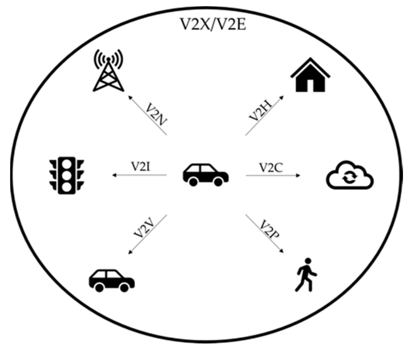
6.1. Wireless Communication as a Key Enabling Technology

To promote road safety, vehicle-to-vehicle (V2V) and vehicle-to-infrastructure (V2I) communication are essential elements when evolving towards higher levels of autonomous vehicles. When V2V and V2I systems are combined, a completely connected system is obtained, namely, the V2X system. As shown in Figure 13, for a true V2X system, also vehicle-to-pedestrian (V2P), vehicle-to-network (V2N), vehicle-to-cloud (V2C) and vehicle-to-home (V2H) should be considered.
There exist multiple means to establish this communication, each with its own advantages and drawbacks. Well-known technologies for wireless communication are 5G, Bluetooth and Wi-Fi. Although in some cases, these radio wave technologies might provide enough bandwidth for V2V and V2I communication, it is essential to consider situations where this is not possible. Examples are the countryside, badly covered regions in cities, regions with a lot of electromagnetic interference, indoor and subterranean areas, such as parking lots and tunnels, etc. An alternative to radio wave communication is Light Fidelity (Li-Fi), which uses visible and infrared light for data traffic. The term Li-Fi was first introduced to the wide public by Professor Harald Haas, in 2011 [93]. He demonstrated how data can be transmitted towards a photoreceiver by using light from a simple LED (light-emitting diode) desk lamp. This can be done by modulating the light radiation from existing lighting infrastructure, e.g., streetlight, car headlights, etc. With the use of suitable photoreceivers, either a unidirectional or bidirectional communication link can be established with a bandwidth that can yield up to a data rate 100 times larger compared to Wi-Fi [93].
The technical implementation of Li-Fi is displayed in Figure 14. The intensity of the light emitted by the transmitter of solid-state light-sources, such as a LED or a Laser Diode (LD), is modulated by an electrical driver by turning the current on and off. This type of modulation is called intensity modulation (IM). The maximum frequency of the human visual system can observe, lies between 30 Hz and 60 Hz. The flickering caused by the IM ranges from hundreds of MHz up to 1 GHz, depending on the RC properties of the source and by consequence, it is thus impossible for a human observer to perceive any flickering. The driver is powered and connected to either the world wide web or a local server through well-known technologies, such as power-line-communication (PLC) or Power-over-Ethernet (PoE). At the receiver side, a photodiode or photoreceiver turns the light signal back into an electrical signal, ready for processing. The received signal must be processed by a processing unit to fetch the data residing in it.
With the increasing use of solid-state lighting, both in cars (head- and taillights), as well as in the infrastructure (road lighting and traffic lights), implementing Li-Fi is relatively easy. Relatively, as for comparable systems using classic RF-based communication (like dedicated short-range communications or DSRC), a whole new infrastructure needs to be built. A Li-Fi transmitter can be as simple as a LED light, meaning that the existing lighting infrastructure could be used as Li-Fi transmitters. It can then be used as an access point for information for both vehicles and other road users (pedestrians, bikes, etc.). The implementation cost is thus limited, and the available access points are abundant. The current “dumb” road lighting has the potential to evolve towards a “smart” lighting infrastructure with limited efforts. Nevertheless, the technical implementation of Li-Fi remains a challenge, as has been explained earlier. But the implementation costs are lower compared to alternatives.
A potential application and new trend of the Li-Fi in V2X is the communication of critical traffic data in-between vehicles, as well as from vehicle to infrastructure or vice-versa. Vehicles or their drivers will be able to respond much faster, which increases the overall safety. Also, the level of traffic monitoring can be improved, which leads to better traffic regulation and traffic flow, and this will impact the energy demand. Moreover, the Li-Fi provides fast internet connection and consequently enables the transfer of not only traffic data, but any kind of data. Adopting multisensorial input and various communication channels, i.e., the Li-Fi together with other wireless communication technologies, such as 5G and Wi-Fi, will result in more reliable autonomous and connected vehicles, thus improving the road safety.

6.2. Shared Autonomous Electric Vehicles (SAEV)

Shared autonomous vehicles (SAV) are gaining general interest, due to the fact that they could be a cheaper, safer and more efficient versions of today’s ride-sourcing and car-sharing options [91]. Moreover, the electric version, SAEVs, could compete economically with current mobility solutions and further reduce environmental impact compared to conventional combustion engine vehicles. They are, therefore, viewed as a promising component of smart mobility [92]. The deployment of SAEVs presents numerous challenges. From an economic point of view, to create viable business models, it will be crucial to estimate passenger demand and determine the willingness to use and to pay for this service [92]. From the mobility viewpoint, vehicle supply will need to match the travel demand. SAEVs could improve mobility, especially for the elderly and people with reduced mobility [94,95,96]. However, a concern in this regard is the digital divide between people where socially disadvantaged people are less tech-savvy and reluctant to accept new technologies. Fleet management must ensure service to passengers, while the electric nature of the AEVs requires taking the driving range and vehicle charging into account. For the SAEVs fleet charging, the anticipated volume, location and power levels of the charging stations are important [91]. Studies on SAEV that include the charging aspects [91,97,98] have so far only included a spatial distribution or rule-based introduction, yet do not look at other attributes to assess the suitability of a location, nor do they check grid constraints or impacts which, thus, remains an ongoing research topic. Additionally, from an energy point of view, the mass introduction of electric vehicles raises concerns with regards to electricity supply and electricity grid. However, research has demonstrated that large scale introduction of EVs only moderately increases electricity demand and presents a great opportunity to balance the electricity grid through various ancillary services with smart- or bidirectional charging (vehicle-to-grid) [99] and can facilitate further deployment of renewable energy sources (RES) by balancing their intermittent nature [100], as explained in the previous chapter. The SAEV fleets have a high degree of controllability and coordination and present an opportunity in this regard. This integration of the SAEV system in the electricity grid is, therefore, an essential development. It was found by modelling some alternative scenarios that SAEV fleets are likely to electrify quickly, and therefore, contribute to reducing CO2 emissions in combination with the further decarbonisation of electricity generation and that the ability to optimally schedule SAEV charging is a more important determinant of positive environmental and economic outcomes than the travel demand effects of SAEV fleets [101].
Studies, thus, currently indicate the potential of SAEV fleets inherent to both their autonomous and electric nature that make way for optimised behaviour (environmental, economic, service) of the fleet. It does, however, present a challenging fleet management problem dealing with mobility and energy demand which requires further research alongside the technological advancement of key enabling technologies.

7. Conclusions

This paper provides an overview of the current state of the art in electric vehicle developments and innovation, related to the vehicle components, their charging infrastructure and interaction with the grid, but also related to battery material sciences and power electronics engineering up to environmental assessments, market considerations and synergies with shared and autonomous vehicles. This paper also provides recommendations for future developments and trends.
The EV purchase price and driving range have improved, due to the current optimisation in battery technologies and their system interfaces. This will be further improved by making use of innovative solid-state batteries. Solid-state batteries have the potential to reach higher energy density values. This promising novel technology together with the development of self-healing batteries and the integration of embedded sensors in the cell, will provide more durable and safer batteries. As such, the specific energy of the battery can be improved from 110 Wh/kg in 2010 up to 450 Wh/kg by 2030. In the same time the battery energy density can increase from 310 Wh/L in 2010 up to 1100 Wh/L by 2030. The battery cost can be reduced from 1000 €/kWh to 80 €/kWh or less by 2030. This will lead to an increased driving range or a lower vehicle weight and this at a lower battery cost. The size of the battery in 2010 was typically 30 kWh and by 2030 the battery capacity could be over 80kWh.
Digital twin (DT) will be an enabler tool for further optimisation of the efficiency and reliability of EVs and offer powertrain design for high reliability. Thus, this will provide new trends and directions—such as digital twin for design (DT4D), digital twin for control design (DT4CD), digital twin for virtual validation (DT4VV) and digital twin for reliability (DT4R)—for new and efficient and cost-effective powertrains.
Moreover, emerging wide bandgap (WBG) technologies in power electronics interfaces and their integration concepts can provide a significant efficiency improvement not only in the EV powertrains, but also in charging systems enabling high-performance V2X systems. The latter will enable an intelligent utilisation of energy sources with smart energy management strategies for efficient and seamless integration into grid networks. Ultrafast and/or bidirectional chargers will allow better integration of renewable energy sources into the grid, making the use of electric vehicles even cleaner as they are today. The traction inverter’s power density can be improved from 10 kW/L in 2010 to up to 65 kW/L by 2030, which results in a volume reduction up to 40%. In the same time the peak inverter efficiency has increased from 92% (2010) to up to 98% (2030) by making use of this wide bandgap technology. This will enhance the driving range with 8%. A similar trend can be observed for the battery charger, where efficiencies up to 99% could be achieved by 2030, leading to a reduction of the charging cost by 20%. Improved efficiencies will result in a decrease of vehicle energy consumption from 0.22 kWh/km down to 0.15 kWh/km (2030).
The environmental impact of electric vehicles mainly depends on how electricity is produced. Based on the EU energy mix the CO2 emissions were around 300 g/kWh in 2010. It is expected by an increased share of renewable energy sources that by 2030 the CO2 emissions would reduce below at least 200 g/kWh. Considering the electric vehicle consumption and emissions to produce the electricity, the CO2 emissions per vehicle will decrease from 66 g/km in 2010 to below 30g/km in 2030.
Introducing shared autonomous electric vehicles (SAEVs) as an alternative to private car ownership will allow for further optimisation of the energy demand and grid management in the light of the transition towards thorough electrification. The seamless integration of electrified and automated fleets in the energy sector will also be a key enabler realising sustainable energy communities, where increased levels of renewable energy are locally produced and consumed. The level of automation (SAE) has shifted from level 0 to 1 in 2010, is currently evolving from level 2 to 3 and will attain up to 4 by 2030.
Finally, including the Li-Fi technology in the state-of-the-art wireless communication systems will lead to more redundant, fast and low-cost data transfer. Since the demand for mobile data is increasing much faster than the supply, it is indispensable to use novel technologies, such as Li-Fi in as many ways as possible. This will increase road safety and allow for better energy management of the AEV fleet.

Author Contributions

J.V.M. took the initiative for this paper, wrote the introduction, and brought everything together. O.H. and M.E.B. were in charge of the Section 2 and Section 4 on propulsion systems (digital twin), WBG power electronics and charging technology. M.B. drafted Section 3 on the battery technology (Solid state, self healing and sensing). M.M. and T.C. wrote the Section 5 on sustainable energy communities and LCA. Finally, C.D.C. and V.A.J. provided the input for shared autonomous electric vehicles and LiFi technology of Section 6. All authors have read and agreed to the published version of the manuscript.

Funding

This research was partly funded by the European Commission projects: BAT4EVER (ID: 957225), SPARTACUS (ID: 957221), BATTERY2030PLUS (ID: 957213), RENewAble Integration and SuStainAbility iN energy CommunitiEs; Renaissance (H2020 - ID nr 824342), HIFI Elements (ID 769935), OBELICS (ID 769506), HiPERFORM (ECSEL JU no. 783174) as well as funded by VLAIO, projects: OPTIBIDS: Optimized bidirectional & Smart vehicle charging in local energy systems and SBO ModulAr.

Acknowledgments

We acknowledge Flanders Make for the support to our research group. We also acknowledge the European Commission for the support to the above-mentioned European projects as well as Flanders Innovation & Entrepreneurship (VLAIO).

Conflicts of Interest

The author declares no conflict of interest.

References

  1. Chan, C.C.; Wong, Y.S.; Bouscayrol, A.; Chen, K. Powering Sustainable Mobility: Roadmaps of Electric, Hybrid, and Fuel Cell Vehicles. Proc. IEEE 2009, 97, 603–607. [Google Scholar] [CrossRef]
  2. Lebeau, K.; van Mierlo, J.; Lebeau, P.; Mairesse, O.; Macharis, C. Consumer attitudes towards battery electric vehicles: A large-scale survey. Int. J. Electr. Hybrid Veh. 2013, 5, 28–41. [Google Scholar] [CrossRef]
  3. BloombergNEF. BloombergNEF’s 2019 Battery Price Survey BNEF. Available online: https://about.bnef.com/blog/battery-pack-prices-fall-as-market-ramps-up-with-market-average-at-156-kwh-in-2019/ (accessed on 3 February 2021).
  4. Berckmans, G.; Messagie, M.; Smekens, J.; Omar, N.; Vanhaverbeke, L.; van Mierlo, J. Cost projection of state of the art lithium-ion batteries for electric vehicles up to 2030. Energies 2017, 10, 1314. [Google Scholar] [CrossRef] [Green Version]
  5. Vijayagopal, R.; Rousseau, A. Benefits of electrified powertrains in medium-and heavy-duty vehicles. World Electr. Veh. J. 2020, 11, 12. [Google Scholar] [CrossRef] [Green Version]
  6. Simeu, S.K.; Brokate, J.; Stephens, T.; Rousseau, A. Factors influencing energy consumption and cost-competiveness of plug-in electric vehicles. World Electr. Veh. J. 2018, 9, 23. [Google Scholar] [CrossRef] [Green Version]
  7. Islam, E.S.; Moawad, A.; Kim, N.; Rousseau, A. Vehicle electrification impacts on energy consumption for different connected-autonomous vehicle scenario runs. World Electr. Veh. J. 2020, 11, 9. [Google Scholar] [CrossRef] [Green Version]
  8. Messagie, M.; Boureima, F.S.; Coosemans, T.; Macharis, C.; van Mierlo, J. A range-based vehicle life cycle assessment incorporating variability in the environmental assessment of different vehicle technologies and fuels. Energies 2014, 7, 1467–1482. [Google Scholar] [CrossRef]
  9. Marmiroli, B.; Messagie, M.; Dotelli, G.; van Mierlo, J. Electricity Generation in LCA of Electric Vehicles: A Review. Appl. Sci. 2018, 8, 1384. [Google Scholar] [CrossRef] [Green Version]
  10. Rangaraju, S. Impacts of electricity mix, charging profile, and driving behavior on the emissions performance of battery electric vehicles. A Belgian case study. Appl. Energy 2015, 148, 496–505. [Google Scholar] [CrossRef]
  11. Chan, C.C. The state of the art of electric, hybrid, and fuel cell vehicles. Proc. IEEE 2007, 95, 704–718. [Google Scholar] [CrossRef]
  12. Yong, J.Y.; Ramachandaramurthy, V.K.; Tan, K.M.; Mithulananthan, N. A review on the state-of-the-art technologies of electric vehicle, its impacts and prospects. Renew. Sustain. Energy Rev. 2015, 49, 365–385. [Google Scholar] [CrossRef]
  13. Shariff, S.M.; Iqbal, D.; Alam, M.S.; Ahmad, F. A State of the Art Review of Electric Vehicle to Grid (V2G) technology. In IOP Conference Series: Materials Science and Engineering; IOP Publishing: Bristol, UK, 2019; Volume 561. [Google Scholar]
  14. Tran, D.D.; Vafaeipour, M.; el Baghdadi, M.; Barrero, R.; van Mierlo, J.; Hegazy, O. Thorough state-of-the-art analysis of electric and hybrid vehicle powertrains: Topologies and integrated energy management strategies. Renew. Sustain. Energy Rev. 2020, 119, 109596. [Google Scholar] [CrossRef]
  15. Hannan, M.A.; Hoque, M.M.; Hussain, A.; Yusof, Y.; Ker, P.J. State-of-the-Art and Energy Management System of Lithium-Ion Batteries in Electric Vehicle Applications: Issues and Recommendations. IEEE Access 2018, 6, 19362–19378. [Google Scholar] [CrossRef]
  16. Foley, A.M.; Winning, I.J.; Gallachóir, B.P. State-of-the-art in electric vehicle charging infrastructure. In Proceedings of the 2010 IEEE Vehicle Power and Propulsion Conference, Lille, France, 1–3 September 2010. [Google Scholar]
  17. Ehsani, M.; Gao, Y.; Emadi, A. Electric Propulsion Systems. In Modern Electric, Hybrid Electric, and Fuel Cell Vehicles; CRC Press; Taylor & Francis Group: Oxford, UK, 2017. [Google Scholar]
  18. Chen, K.; Bouscayrol, A.; Lhomme, W. Energetic Macroscopic Representation and Inversion-based Control: Application to an Electric Vehicle with an Electrical Differential. J. Asian Electr. Veh. 2008, 6, 1097–1102. [Google Scholar] [CrossRef]
  19. Chan, C.C.; Bouscayrol, A.; Chen, K. Electric, hybrid, and fuel-cell vehicles: Architectures and modeling. IEEE Trans. Veh. Technol. 2010, 59, 589–598. [Google Scholar] [CrossRef]
  20. Koot, M.; Kessels, J.T.B.A.; de Jager, B.; Heemels, W.P.M.H.; van den Bosch, P.P.J.; Steinbuch, M. Energy management strategies for vehicular electric power systems. IEEE Trans. Veh. Technol. 2005, 54, 771–782. [Google Scholar] [CrossRef]
  21. Hofman, T.; Steinbuch, M.; van Druten, R.; Serrarens, A. Rule-based energy management strategies for hybrid vehicles. Int. J. Electr. Hybrid Veh. 2007, 1, 71–94. [Google Scholar] [CrossRef]
  22. Madni, A.; Madni, C.; Lucero, S. Leveraging Digital Twin Technology in Model-Based Systems Engineering. Systems 2019, 7, 7. [Google Scholar] [CrossRef] [Green Version]
  23. Wu, B.; Widanage, W.D.; Yang, S.; Liu, X. Battery digital twins: Perspectives on the fusion of models, data and artificial intelligence for smart battery management systems. Energy AI 2020, 1, 100016. [Google Scholar] [CrossRef]
  24. Microsemi, P.P.G. Gallium Nitride (GaN) versus Silicon Carbide (SiC) in the High Frequency (RF) and Power Switching Applications. Available online: https://www.richardsonrfpd.com/docs/rfpd/Microsemi-A-Comparison-of-Gallium-Nitride-Versus-Silicon-Carbide.pdf (accessed on 3 February 2021).
  25. Rasool, H.; el Baghdadi, M.; Rauf, A.M.; Zhaksylyk, A.; Hegazy, O. A rapid non-linear computation model of power loss and electro thermal behaviour of three-phase inverters in EV drivetrains. In Proceedings of the 2020 International Symposium on Power Electronics, Electrical Drives, Automation and Motion (SPEEDAM), Sorrento, Italy, 24–26 June 2020. [Google Scholar]
  26. Keshmiri, N.; Wang, D.; Agrawal, B.; Hou, R.; Emadi, A. Current Status and Future Trends of GaN HEMTs in Electrified Transportation. IEEE Access 2020, 8, 70553–70571. [Google Scholar] [CrossRef]
  27. Sewergin, A.; Wienhausen, A.H.; Oberdieck, K.; de Doncker, R.W. Modular bidirectional full-SiC DC-DC converter for automotive applications. In Proceedings of the 2017 IEEE 12th International Conference on Power Electronics and Drive Systems (PEDS), Honolulu, HI, USA, 12–15 December 2017. [Google Scholar]
  28. Rui, R. Power Stage of 48V BSG Inverter. Infineon Appl. Note. Available online: https://www.infineon.com/dgdl/Infineon-20180802_AN-Power_stage_of_48V_BSG_inverter_V2.2-AN-v01_00-EN.pdf?fileId=5546d46265487f7b0165a3863b8e5bcf (accessed on 3 February 2021).
  29. Liu, Z.; Li, B.; Lee, F.C.; Li, Q. High-Efficiency High-Density Critical Mode Rectifier/Inverter for WBG-Device-Based On-Board Charger. IEEE Trans. Ind. Electron. 2017, 64, 9114–9123. [Google Scholar] [CrossRef]
  30. Rasool, H.; Zhaksylyk, A.; Chakraborty, S.; el Baghdadi, M.; Hegazy, O. Optimal Design Strategy and Electro-Thermal Modelling of a High-Power Off-Board Charger for Electric Vehicle Applications. In Proceedings of the 2020 Fifteenth International Conference on Ecological Vehicles and Renewable Energies (EVER), Monte-Carlo, Monaco, 10–12 September 2020; pp. 1–8. [Google Scholar]
  31. Chakraborty, S.; Vu, H.; Hasan, M.M.; Tran, D.; el Baghdadi, M.; Hegazy, O. DC-DC Converter Topologies for Electric Vehicles, Plug-in Hybrid Electric Vehicles and Fast Charging Stations: State of the Art and Future Trends. Energies 2019, 12, 1569. [Google Scholar] [CrossRef] [Green Version]
  32. Lu, L.; Han, X.; Li, J.; Hua, J.; Ouyang, M. A review on the key issues for lithium-ion battery management in electric vehicles. J. Power Sources 2013, 226, 272–288. [Google Scholar] [CrossRef]
  33. Fuchs, G.; Lunz, B.; Leuthold, M.; Sauer, D.U. Technology Overview on Electricity Storage. Inst. Power Electron. Electr. Drives 2012. [Google Scholar] [CrossRef]
  34. Li, M.; Lu, J.; Chen, Z.; Amine, K. 30 Years of Lithium-Ion Batteries. Adv. Mater. 2018, 30, 1800561. [Google Scholar] [CrossRef] [Green Version]
  35. Sun, Y.K.; Myung, S.T.; Park, B.C.; Prakash, J.; Belharouak, I.; Amine, K. High-energy cathode material for long-life and safe lithium batteries. Nat. Mater. 2009, 8, 320–324. [Google Scholar] [CrossRef]
  36. Philippot, M.; Alvarez, G.; Ayerbe, E.; van Mierlo, J.; Messagie, M. Eco-efficiency of a lithium-ion battery for electric vehicles: Influence of manufacturing country and commodity prices on ghg emissions and costs. Batteries 2019, 5, 23. [Google Scholar] [CrossRef] [Green Version]
  37. Schmuch, R.; Wagner, R.; Hörpel, G.; Placke, T.; Winter, M. Performance and cost of materials for lithium-based rechargeable automotive batteries. Nat. Energy 2018, 3, 267–278. [Google Scholar] [CrossRef]
  38. Xie, J.; Lu, Y.C. A retrospective on lithium-ion batteries. Nat. Commun. 2020, 11, 1–4. [Google Scholar] [CrossRef]
  39. Gopalakrishnan, R.; Goutam, S.; Miguel Oliveira, L.; Timmermans, J.M.; Omar, N.; Messagie, M.; Van den Bossche, P.; Van Mierlo, J. A comprehensive study on rechargeable energy storage technologies. J. Electrochem. Energy Convers. Storage 2016. [Google Scholar] [CrossRef]
  40. Berckmans, G.; De Sutter, L.; Marinaro, M.; Smekens, J.; Jaguemont, J.; Wohlfahrt-Mehrens, M.; van Mierlo, J.; Omar, N. Analysis of the effect of applying external mechanical pressure on next generation silicon alloy lithium-ion cells. Electrochim. Acta 2019, 306, 387–395. [Google Scholar] [CrossRef]
  41. Edström, K. BATTERY 2030+. Inventing the Sustainable Batteries of the Future. Research Needs and Future Actions. Available online: https://battery2030.eu/digitalAssets/860/c_860904-l_1-k_roadmap-27-march.pdf (accessed on 3 February 2021).
  42. Till, B. Global EV Outlook 2019 to Electric Mobility; IEA: London, UK, 2019. [Google Scholar]
  43. Pasta, M.; Armstrong, D.; Brown, Z.L.; Bu, J.; Castell, M.R.; Chen, P.; Cocks, A.; Corr, S.A.; Cussen, E.J.; Darnbrough, E. 2020 roadmap on solid-state batteries. J. Phys. Energy 2020, 2, 032008. [Google Scholar] [CrossRef]
  44. Randau, S.; Weber, D.A.; Kötz, O.; Koerver, R.; Braun, P.; Weber, A.; Ivers-Tiffée, E.; Adermann, T.; Kulisch, J.; Zeier, W.G.; et al. Benchmarking the performance of all-solid-state lithium batteries. Nat. Energy 2020, 5, 259–270. [Google Scholar] [CrossRef]
  45. Albertus, P.; Babinec, S.; Litzelman, S.; Newman, A. Status and challenges in enabling the lithium metal electrode for high-energy and low-cost rechargeable batteries. Nat. Energy 2018, 3, 16–21. [Google Scholar] [CrossRef]
  46. Peled, E.; Menkin, S. Review—SEI: Past, Present and Future. J. Electrochem. Soc. 2017, 164, A1703. [Google Scholar] [CrossRef]
  47. Forsyth, M.; Porcarelli, L.; Wang, X.; Goujon, N.; Mecerreyes, D. Innovative Electrolytes Based on Ionic Liquids and Polymers for Next-Generation Solid-State Batteries. Acc. Chem. Res. 2019, 52, 686–694. [Google Scholar] [CrossRef] [PubMed]
  48. Jeong, K.; Park, S.; Lee, S.Y. Revisiting polymeric single lithium-ion conductors as an organic route for all-solid-state lithium ion and metal batteries. J. Mater. Chem. A 2019, 7, 1917–1935. [Google Scholar] [CrossRef]
  49. Kerman, K.; Luntz, A.; Viswanathan, V.; Chiang, Y.-M.; Chen, Z. Review—Practical Challenges Hindering the Development of Solid State Li Ion Batteries. J. Electrochem. Soc. 2017, 164, A1731. [Google Scholar] [CrossRef]
  50. Garbayo, I.; Struzik, M.; Bowman, W.J.; Pfenninger, R.; Stilp, E.; Rupp, J.L.M. Glass-Type Polyamorphism in Li-Garnet Thin Film Solid State Battery Conductors. Adv. Energy Mater. 2018, 8, 1702265. [Google Scholar] [CrossRef]
  51. Smekens, J.; Gopalakrishnan, R.; Steen, N.V.; Omar, N.; Hegazy, O.; Hubin, A.; Van Mierlo, J. Influence of electrode density on the performance of Li-ion batteries: Experimental and simulation results. Energies 2016, 9, 104. [Google Scholar] [CrossRef] [Green Version]
  52. Krauskopf, T.; Mogwitz, B.; Rosenbach, C.; Zeier, W.G.; Janek, J. Diffusion Limitation of Lithium Metal and Li–Mg Alloy Anodes on LLZO Type Solid Electrolytes as a Function of Temperature and Pressure. Adv. Energy Mater. 2019, 9, 1902568. [Google Scholar] [CrossRef] [Green Version]
  53. Truchot, C.; Dubarry, M.; Liaw, B.Y. State-of-charge estimation and uncertainty for lithium-ion battery strings. Appl. Energy 2014, 119, 218–227. [Google Scholar] [CrossRef]
  54. Li, Y.; Liu, K.; Foley, A.M.; Zülke, A.; Berecibar, M.; Nanini-Maury, E.; Van Mierlo, J.; Hoster, H.E. Data-driven health estimation and lifetime prediction of lithium-ion batteries: A review. Renew. Sustain. Energy Rev. 2019, 113, 109254. [Google Scholar] [CrossRef]
  55. de Sutter, L.; Berckmans, G.; Marinaro, M.; Wohlfahrt-Mehrens, M.; Berecibar, M.; van Mierlo, J. Mechanical behavior of Silicon-Graphite pouch cells under external compressive load: Implications and opportunities for battery pack design. J. Power Sources 2020, 451, 227774. [Google Scholar] [CrossRef]
  56. Campanella, A.; Döhler, D.; Binder, W.H. Self-Healing in Supramolecular Polymers. Macromol. Rapid Commun. 2018, 39, 1700739. [Google Scholar] [CrossRef] [PubMed]
  57. Wang, C.; Wu, H.; Chen, Z.; Mcdowell, M.T.; Cui, Y.; Bao, Z. Self-healing chemistry enables the stable operation of silicon microparticle anodes for high-energy lithium-ion batteries. Nat. Chem. 2013, 5, 1042. [Google Scholar] [CrossRef] [PubMed]
  58. Bobba, S.; Mathieux, F.; Blengini, G.A. How will second-use of batteries affect stocks and flows in the EU? A model for traction Li-ion batteries. Resour. Conserv. Recycl. 2019, 145, 279–291. [Google Scholar] [CrossRef]
  59. Berecibar, M.; Gandiaga, I.; Villarreal, I.; Omar, N.; van Mierlo, J.; van den Bossche, P. Critical review of state of health estimation methods of Li-ion batteries for real applications. Renew. Sustain. Energy Rev. 2016, 56, 572–587. [Google Scholar] [CrossRef]
  60. Berecibar, M. Machine-learning techniques used to accurately predict battery life. Nature 2019, 568, 325–326. [Google Scholar] [CrossRef]
  61. Langer, E. Liquid Cooling in Electric Vehicles—What to Know to Keep EVs on the Go By; CPC: Preston, UK, 2019. [Google Scholar]
  62. SHabib; Khan, M.M.; Abbas, F.; Tang, H. Assessment of electric vehicles concerning impacts, charging infrastructure with unidirectional and bidirectional chargers, and power flow comparisons. Int. J. Energy Res. 2018, 42, 3416–3441. [Google Scholar]
  63. Chatterjee, P.; Hermwille, M. Tackling the Challenges of Electric Vehicle Fast Charging. ATZelectron. Worldw. 2020, 15, 18–22. [Google Scholar] [CrossRef]
  64. Dusmez, S.; Cook, A.; Khaligh, A. Comprehensive analysis of high quality power converters for level 3 off-board chargers. In Proceedings of the 2011 IEEE Vehicle Power and Propulsion Conference, Chicago, IL, USA, 6–9 September 2011. [Google Scholar]
  65. Salgado-Herrera, N.M.; Anaya-Lara, O.; Campos-Gaona, D.; Medina-Rios, A.; Tapia-Sanchez, R.; Rodriguez-Rodriguez, J.R. Active Front-End converter applied for the THD reduction in power systems. In Proceedings of the 2018 IEEE Power & Energy Society General Meeting (PESGM), Portland, OR, USA, 5–10 August 2018. [Google Scholar]
  66. Kesler, M.; Kisacikoglu, M.C.; Tolbert, L.M. Vehicle-to-grid reactive power operation using plug-in electric vehicle bidirectional offboard charger. IEEE Trans. Ind. Electron. 2014, 61, 6778–6784. [Google Scholar] [CrossRef]
  67. Vu, H.N.; Abdel-Monem, M.; el Baghdadi, M.; van Mierlo, J.; Hegazy, O. Multi-objective optimization of on-board chargers based on state-of-the-art 650V GaN power transistors for the application of electric vehicles. In Proceedings of the 2019 IEEE Vehicle Power and Propulsion Conference (VPPC), Hanoi, Vietnam, 14–17 October 2019. [Google Scholar]
  68. Yilmaz, M.; Krein, P.T. Review of Battery Charger Topologies, Charging Power Levels, and Infrastructure for Plug-In Electric and Hybrid Vehicles. IEEE Trans. Power Electron. 2013, 28, 2151–2169. [Google Scholar] [CrossRef]
  69. Xue, L.; Shen, Z.; Boroyevich, D.; Mattavelli, P.; Diaz, D. Dual Active Bridge-Based Battery Charger for Plug-in Hybrid Electric Vehicle With Charging Current Containing Low Frequency Ripple. IEEE Trans. Power Electron. 2015, 30, 7299–7307. [Google Scholar] [CrossRef] [Green Version]
  70. Li, B.; Lee, F.C.; Li, Q.; Liu, Z. Bi-directional on-board charger architecture and control for achieving ultra-high efficiency with wide battery voltage range. In Proceedings of the 2017 IEEE Applied Power Electronics Conference and Exposition (APEC), Tampa, FL, USA, 26–30 March 2017; pp. 3688–3694. [Google Scholar]
  71. Zhaksylyk, A.; Rasool, H.; Geury, T.; el Baghdadi, M.; Hegazy, O. Masterless Control of Parallel Modular Active front-end (AFE) Systems for Vehicles and Stationary Applications. In Proceedings of the 2020 Fifteenth International Conference on Ecological Vehicles and Renewable Energies (EVER), Monte-Carlo, Monaco, 10–12 September 2020; pp. 1–6. [Google Scholar]
  72. Rachid, A.; El Fadil, H.; Koundi, M.; El Idrissi, Z.; Tahri, A.; Giri, F.; Guerrero, J.M. PQ Theory-Based Control of Single-Stage V2G Three-Phase BEV Charger for High-Voltage Battery. IFAC-PapersOnLine 2019, 52, 73–78. [Google Scholar] [CrossRef]
  73. Salgado-Herrera, N.M.; Campos-Gaona, D.; Anaya-Lara, O.; Medina-Rios, A.; Tapia-Sánchez, R.; Rodríguez-Rodríguez, J.R. THD reduction in wind energy system using type-4 Wind Turbine/PMSG applying the active front-end converter parallel operation. Energies 2018, 11, 2458. [Google Scholar] [CrossRef] [Green Version]
  74. Xing, K.; Lee, F.C.; Borojevic, D.; Ye, Z.; Mazumder, S. Interleaved PWM with discontinuous space-vector modulation. IEEE Trans. Power Electron. 1999, 14, 906–917. [Google Scholar] [CrossRef]
  75. Zhang, Z.; Zhang, Z.; Xie, S.; Yang, C. A control strategy for paralleled bi-directional DC-DC converters used in energy storage systems. In Proceedings of the 2016 IEEE Energy Conversion Congress and Exposition (ECCE), Milwaukee, WI, USA, 18–22 September 2016. [Google Scholar]
  76. Pei, Y.; Jiang, G.; Yang, X.; Wang, Z. Auto-Master-Slave control technique of parallel inverters in distributed AC power systems and UPS. In Proceedings of the 2004 IEEE 35th Annual Power Electronics Specialists Conference (IEEE Cat. No.04CH37551), Aachen, Germany, 20–25 June 2004; Volume 3. [Google Scholar]
  77. Meng, P.; Jian, Z.; Li, W.; Wang, Y. The study and application of CAN communication of rectifier parallel operation control system. In Proceedings of the 2016 19th International Conference on Electrical Machines and Systems (ICEMS), Chiba, Japan, 13–16 November 2016. [Google Scholar]
  78. Zhang, H.; Shi, Y.; Wang, J.; Chen, H. A New Delay-Compensation Scheme for Networked Control Systems in Controller Area Networks. IEEE Trans. Ind. Electron. 2018, 65, 7239–7247. [Google Scholar] [CrossRef]
  79. Gray, M.S.; Gao, Z.; Button, R.M. Distributed, master-less control of modular DC-DC converters. In Proceedings of the 2nd International Energy Conversion Engineering Conference, Providence, RI, USA, 16–19 August 2004; Volume 3. [Google Scholar]
  80. Blaabjerg, F.; Teodorescu, R.; Liserre, M.; Timbus, A.V. Overview of control and grid synchronization for distributed power generation systems. IEEE Trans. Ind. Electron. 2006, 53, 1398–1409. [Google Scholar] [CrossRef] [Green Version]
  81. Messagie, M.; Mertens, J.; Oliveira, L.; Rangaraju, S.; Sanfelix, J.; Coosemans, T.; Van Mierlo, J.; Macharis, C. The hourly life cycle carbon footprint of electricity generation in Belgium, bringing a temporal resolution in life cycle assessment. Appl. Energy 2014, 134, 469–476. [Google Scholar] [CrossRef]
  82. Van Mierlo, J. The World Electric Vehicle Journal, The Open Access Journal for the e-Mobility Scene. World Electr. Veh. J. 2018, 9, 1. [Google Scholar] [CrossRef] [Green Version]
  83. i, Y.; Messagie, M.; Berecibar, M.; Hegazy, O.; Omar, N.; Van Mierlo, J. The impact of the vehicle-to-grid strategy on lithium-ion battery ageing process. In Proceedings of the 31st International Electric Vehicle Symposium and Exhibition (EVS 2018), Kobe, Japan, 30 September–3 October 2018. [Google Scholar]
  84. van Kriekinge, G.; de Cauwer, C.; van Mierlo, J.; Coosemans, T. Techno-Economical Assessment of Vehicle-to-Grid in a Microgrid: Case Study. In Proceedings of the 33th International Electric Vehicle Symposium and Exhibition (EVS 2020), Portland, OR, USA, 14–17 June 2020. [Google Scholar]
  85. Syed, A.; Crispeels, T.; Jahir Roncancio Marin, J.; Cardellini, G.; De Cauwer, C.; Coosemans, T.; van Mierlo, J.; Messagie, M. A Novel Method to Value the EV-Fleet’s Grid Balancing Capacity. In Proceedings of the 33th International Electric Vehicle Symposium and Exhibition (EVS 2020), Portland, OR, USA, 14–17 June 2020. [Google Scholar]
  86. De Cauwer, C.; van Kriekinge, G.; van Mierlo, J.; Coosemans, T.; Messagie, M. Integration of Vehicle-to-Grid in Local Energy Systems: Concepts and Specific Requirements. In Proceedings of the 33th International Electric Vehicle Symposium and Exhibition (EVS 2020), Portland, OR, USA, 14–17 June 2020. [Google Scholar]
  87. Arrinda, M.; Berecibar, M.; Oyarbide, M.; Macicior, H.; Muxika, E.; Messagie, M. Levelized cost of electricity calculation of the energy generation plant of a CO2 neutral micro-grid. Energy 2020, 208, 118383. [Google Scholar] [CrossRef]
  88. Hooftman, N.; Messagie, M.; van Mierlo, J.; Coosemans, T. The Paris Agreement and Zero-Emission Vehicles in Europe: Scenarios for the Road Towards a Decarbonised Passenger Car Fleet. In Towards User-Centric Transport in Europe 2; Springer: Cham, Switzerland, 2020. [Google Scholar]
  89. Messagie, M.; Coosemans, T.; van Mierlo, J. The need for uncertainty propagation in life cycle assessment of vehicle technologies. In Proceedings of the 2019 IEEE Vehicle Power and Propulsion Conference (VPPC), Hanoi, Vietnam, 14–17 October 2019. [Google Scholar]
  90. Narayanan, S.; Chaniotakis, E.; Antoniou, C. Shared autonomous vehicle services: A comprehensive review. Transp. Res. Part C Emerg. Technol. 2020, 111, 255–293. [Google Scholar] [CrossRef]
  91. Loeb, B.; Kockelman, K.M. Fleet performance and cost evaluation of a shared autonomous electric vehicle (SAEV) fleet: A case study for Austin, Texas. Transp. Res. Part A Policy Pract. 2019, 121, 374–385. [Google Scholar] [CrossRef]
  92. Golbabaei, F.; Yigitcanlar, T.; Bunker, J. The role of shared autonomous vehicle systems in delivering smart urban mobility: A systematic review of the literature. Int. J. Sustain. Transp. 2020, 1–18. [Google Scholar] [CrossRef]
  93. Haas, H. Wireless Data from Every Light Bulb. Available online: https://www.ted.com/talks/harald_haas_wireless_data_from_every_light_bulb/transcript (accessed on 3 February 2021).
  94. Maurer, M.; Christian Gerdes, J.; Lenz, B.; Winner, H. Autonomous Driving. Technical, Legal and Social Aspects; Springer: Berlin, Germany, 2016. [Google Scholar]
  95. Fagnant, D.J.; Kockelman, K. Preparing a nation for autonomous vehicles: Opportunities, barriers and policy recommendations. Transp. Res. Part A 2015, 77, 167–181. [Google Scholar] [CrossRef]
  96. Cohen, T.; Cavoli, C. Automated vehicles: Exploring possible consequences of government (non)intervention for congestion and accessibility. Transp. Rev. 2019, 39, 129–151. [Google Scholar] [CrossRef] [Green Version]
  97. Chen, T.D.; Kockelman, K.M.; Hanna, J.P. Operations of a shared, autonomous, electric vehicle fleet: Implications of vehicle & charging infrastructure decisions. Transp. Res. Part A Policy Pract. 2016, 94, 243–254. [Google Scholar]
  98. Iacobucci, R.; Mclellan, B.; Tezuka, T. Modeling shared autonomous electric vehicles: Potential for transport and power grid integration. Energy 2018, 158, 148–163. [Google Scholar] [CrossRef] [Green Version]
  99. Miao, K.; Ramachandaramurthy, V.K.; Yong, J.Y. Integration of electric vehicles in smart grid: A review on vehicle to grid technologies and optimization techniques. Renew. Sustain. Energy Rev. 2016, 53, 720–732. [Google Scholar]
  100. Rangaraju, S. Environmental Performance of Battery Electric Vehicles—Implications for Future Integrated Electricity and Transport System. Ph.D. Thesis, Vrije Univeristiet Brussel, Brussels, Belgium, 2018. [Google Scholar]
  101. Jones, E.C.; Leibowicz, B.D. Contributions of shared autonomous vehicles to climate change mitigation. Transp. Res. Part D Transp. Environ. 2019, 72, 279–298. [Google Scholar] [CrossRef]
Figure 1. A concept development of digital twin implementation in MOBI-VUB.
Wevj 12 00020 g001
Figure 2. Material properties comparison of silicon (Si), silicon carbide (SiC) and gallium nitride (GaN) edited from Reference [30].
Wevj 12 00020 g002
Figure 3. Energy density vs specific energy at electrode stack level for state-of-the-art and future cell chemistries in automotive applications. The state-of-the-art Lithium battery chemistry is represented by NMC-622/graphite and NCA (lithium nickel cobalt aluminium oxide)/graphite [37].
Wevj 12 00020 g003
Figure 4. Battery fabrication for process parameter optimisation [51].
Wevj 12 00020 g004
Figure 5. Multiphases-bidirectional on-board charger (OBC) system architecture [67].
Wevj 12 00020 g005
Figure 6. Single phase bidirectional OBC system topologies based on GaN switches. (a) Dual active full bridge (DAFB) converter, (b) CLLC resonant converter [67].
Wevj 12 00020 g006
Figure 7. 600 kW modular DC ultra-fast charger [71].
Wevj 12 00020 g007
Figure 8. Efficiency map of Si- and SiC-based high power off-board charging system.
Wevj 12 00020 g008
Figure 9. Centralised control of modular power electronic converter (PEC) edited from Reference [71].
Wevj 12 00020 g009
Figure 10. Distributed control of modular PEC edited from Reference [71].
Wevj 12 00020 g010
Figure 11. Climate change life cycle assessment (LCA) results [8].
Wevj 12 00020 g011
Figure 12. Single score LCA results [8].
Wevj 12 00020 g012
Figure 13. Vehicle-to-everything protocol.
Wevj 12 00020 g013
Figure 14. The technical implementation of a Li-Fi downlink channel. A similar approach can be adopted for uplink communication, although the points mentioned in the previous section should be considered.
Wevj 12 00020 g014
Table 1. Type of chargers [62].
Type of Chargers Location of ChargerPower Supply/OutputTypical Charging Time
Level 1 Single phase
On-board
Vac: 230 (EU)
Vac: 120 (US)
Output: 12–16 A; ~1.44 kW to ~1.92 kW
8–10 h depending on model, used for home charging
3–8 km of range per hour of charging
Level 2Single/three phase
On-board
Vac: 400 (EU)
Vac: 240 (US)
Output: 15–80 A;
~3.1 kW to ~19.2 kW
4–8 h, available at home and publicly
16–32 km of range per hour of charging
Level 3
DC Fast Chargers (DCFC)
Three-phase
Off-board
Uses a three-phase Vac: 208–600 AC circuit converted to direct current (DC) to the vehicle.
Output: Up to 500 A; 50 kW up to 350 kW
30–60 min
100–130 km of range per hour of charging
Next Generation:
Ultra-Fast Charging System (UFCS)
Three-phase
Off-board
Uses a three-phase Vac: 208–600 AC circuit converted to direct current (DC) to the vehicle.
Output: 800 V, 400 kW or more
Time to charge to a 320 km range: approximately 7.5 min
Publisher’s Note: MDPI stays neutral with regard to jurisdictional claims in published maps and institutional affiliations.

