Article

Integrated Charger-Inverter for High-Performance Electric Motorcycles

1
School of Electrical Engineering, Hanoi University of Science and Technology, Hanoi 11615, Vietnam
2
Department of Teacher Training in Electrical Engineering, King Mongkut’s University of Technology North Bangkok, Bangkok 10800, Thailand
3
Real BPM Co., Ltd., Samutsakorn 74000, Thailand
*
Author to whom correspondence should be addressed.
World Electr. Veh. J. 2021, 12(1), 19; https://doi.org/10.3390/wevj12010019
Submission received: 11 November 2020 / Revised: 20 January 2021 / Accepted: 27 January 2021 / Published: 1 February 2021

Abstract

:
A high-performance electric motorcycle (HPEM) integrated charger-inverter (ICI) with an induction motor (IM) is proposed in this article. Typical components are shared in drive and charge modes, resulting in savings of weight, volume, and cost. A two-stage ICI for AC induction motor powertrain with power factor correction (PFC) and battery charger functions is considered. Despite high voltage ripple on the DC link, a high bandwidth nonlinear controller can reject such a drawback and adequately provide a constant current or constant voltage charging process. The simulation results of 7 kW ICI are provided to validate the effectiveness and feasibility of the proposed system. Finite element analysis (FEA) determines the torque and losses of IM in charging mode.

1. Introduction

In electric vehicles (EVs) application, driving range is one of most important criteria determining whether people will buy an EV. Both battery technology and fast charging infrastructure are thus hugely invested in by governments and private companies. AC charging stations require an on-board charger (OBC), while DC charging stations move charger power electronics, filters, and so on off board [1]. The charging power of a DC charging station can be much higher than that of an AC charging station with OBC regarding weight and volume constraints. In high-performance electric motorcycle (HPEM) application, weight and volume constraints are much more critical than in other type of EVs. Such vehicles in the market can only be installed with a low-power OBC [2]. This results in a long charge duration. Very few high-performance electric vehicles (HPEVs) have DC charging capability, thus they are less practical in countries where bulky and expensive DC charging stations are not well covered [3].
Integrated charger-inverters (ICI) allow using power electronic components as an inverter in driving mode and can be reconfigured by relays and contactors to be used as a charger in charging mode. Several possibilities have been reviewed, including single-phase input, three-phase input, multi-machine, multi-phase machine, and so on [3,4,5,6,7,8,9,10,11,12,13]. However, for motorcycle applications, only three-phase machines have been reasonably considered owing to their weights and volumes.
In the literature, EVs with several types of three-phase electric motors have been proposed, such as permanent magnet synchronous motors (PMSMs), switched-reluctance motors (SRMs), and induction motors (IMs) [14,15,16]. PMSM offers high efficiency [14]. SRMs give cost-effective, but poor efficiency and high ripple torque [15,16]. However, most ICI have IMs. This is because of the IMs’ advantages, such as low maintenance requirements, reliability, and low cost [14,15].
To use the motor’s winding as an inductor for ICI, the motor’s torque must be investigated primarily during the charging process, resulting in low efficiency. For the three-phase ICI with a three-phase synchronous machine, special winding must be used to ensure that the average torque is zero [10]. To nullify the averaged torque, another solution is proposed without any additional component in [11], where the four motors have EVs with a three-phase grid as an energy source. Each phase of the grid is connected directly to the neutral point of the motor. Therefore, the currents of each phase flow through the three windings at the same waveform (zero-sequence stator currents) and cancel the field of each other so that there is no torque production. The applicable motor can be either three-phase IMs or three-phase PMSM. This technique can be applied for the single three-phase motor with an extra leg of the inverter [12] or the two three-phase motor without the extra leg [13] with single-phase grid supply. However, these configurations have one main disadvantage, which is the pulsation current at double grid frequency of battery due to the use of a single-phase grid. Another work is proposed in [17], where a single-phase quasi-Z-source rectifier with an active filter is used. With the active filter to absorb the double grid frequency ripple, the dc-link capacitor, inductor, and capacitor of the quasi-Z-source converter can be reduced to gain a low weight and volume benefit. However, this converter requires a sophisticated controller, especially to control the active filter.
To demonstrate that average torque during the charging process is null, several works proposed it mathematically. Recently, finite element results are used to validate the average torque of PMSMs [18]. However, such an analysis is rare for IMs.
This work focuses on a 7 kW ICI for HPEM. Common components are shared in drive and charge modes. Weight, volume, and cost saving can be expected. The charging power of 7 kW is more usable in the real-world situation, where a 10–14 kWh battery pack can be fully charged in approximately 2 h. Moreover, 50 km of range can be topped up within 20 min.
A two-stage ICI for AC induction machine (IM) powertrain with power factor correction (PFC) as well as battery charger functions are investigated in this work. ICI topology and control algorithm are verified using circuit simulations. Finite element analysis (FEA) determines the torque and losses of IM in charge mode. Finally, simulations are conducted and some results are shown in the last section.

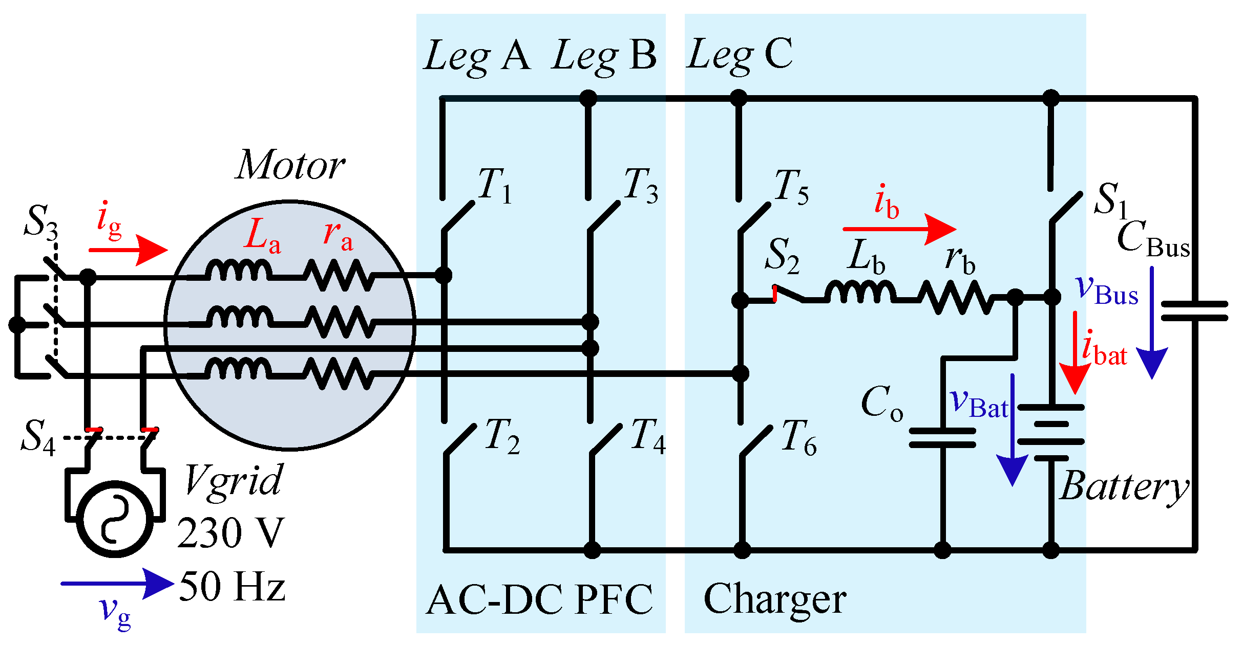
2. Integrated Charger-Inverter

2.1. Topology

The proposed ICI is used for a high-performance electric motorcycle (HPEM). The HPEM is equipped with a 100 kW three-phase IM powertrain driven by a three-phase inverter. In charge mode, six power switches from a three-phase full-bridge inverter and IM’s phase windings are reconfigured and reused as a line filter, as well as a single-phase bridgeless rectifier with power factor correction (PFC) and a bi-directional buck-boost converter for the battery charger.
Figure 1 shows the topology of the electric powertrain in drive mode. It is a conventional three-phase full bridge inverter. A battery pack is directly connected to the DC bus.
In charge mode, S1, S2, S3, and S4 help reconfigure the topology, as shown in Figure 2. Phase-A winding of IM is used as a line filter. Two half-bridge legs (T1, T2, T3, and T4) are controlled as an AC/DC PFC rectifier. Another half-bridge leg (T5 and T6) functions as bi-directional buck-boost DC/DC converter connected to the battery pack through an additional inductor.
The switches S1, S2, S3, and S4 must be controlled to ensure that they function correctly. For driving mode, S1 and S3 are on, while S2 and S4 are off, as shown in Figure 1. In charging mode, S2 and S4 must be on, while S1 and S3 must be off, as detailed in Figure 2.

2.2. Control Algorithm

When the converter system operates in charging mode and supposes that all devices are ideal except inductors ( L a , L b ) , which contain parasitic resistances ( r a , r b ), the system can be expressed in the averaged model as follows:
L a di g dt   =   v g r a i g d PFC v Bus
C Bus dv Bus dt   =   d PFC i g i b
L b di b dt = d Ch v Bus r b i b v Bat
C o dv Bat dt   = i b i bat
where d PFC [ 1 ,   1 ] and d ch [ 0 ,   1 ] are duty cycles corresponding to the switch turn-on time during the switching period T   = 1 / f s for the PFC and charger, respectively. The voltages v g and v Bus are the grid and output voltage, where v bat is the battery voltage. i g and i b are the grid and battery currents, respectively.
In this article, we consider only the AC-DC PFC converter and battery charger; therefore, control of inverter in driving mode is not considered; it can be found in another article.
PFC rectifier control is done in a traditional way, where the cascade control method is used. There are two control loops: inner-current loop and outer-voltage loop, as shown in Figure 3.
Battery charger control is done using constant current (CC) and constant voltage (CV) modes [6]. These modes can be easily defined using a relay with a hysteresis band Δ v Bat = V Batref v Bat . When v Bat is too far from V Batref , the charger charges the battery in CC mode, and otherwise in CV mode. The output from the hysteresis relay is fed into the mode selection block to define the current reference i Batref for the current-control loop. Like for PFC rectifier control, two control loops are used, where an indirect-sliding mode control is used for the inner-current loop [19]; a PI controller is for the outer-voltage loop, as shown in Figure 4. Note that i Batref for the CC mode depends on a specification of battery, whereas the PI controller’s parameters K p and T i are chosen to make the system stable.
To control the output voltage, v Bus and stored energy y = ( 1 / 2 ) Cv Bus 2 in C Bus are considered [20]. Then, it can be expressed as follows:
y ˙ = C Bus   ×   v Bus   ×   v ˙ Bus = p in r g   ×   i g 2 p Bat
where p in is the input power drawn from the grid and p bat is the load power.
Therefore, the following control law is used to control y constant.
y ˙ ref y ˙ + k 1 ( y ref y ) + k 2 ( y ref y ) d τ = 0
The control parameters k 1 and k 2 can be determined referring to a damping factor ξ and angular frequency ω n of the standard second-order system F ( s ) = s 2 + 2 ξ ω n s + ω n 2 , so the controlled system is stable.
The input power p in is the power needed for load, and it can be used as a reference for the input-current loop of the PFC. The current reference can be obtained using the peak current value, corresponding to p in , which is nearly a constant multiple of a unit-sinusoidal waveform. Then, it is fed to a PI controller to govern the input current to be a sinusoidal shape and in phase to the grid voltage. The PI’s parameters are determined using a phase margin in a Bode diagram.
F PI ( s ) = K p + 1 / ( T i s )
For the charging control, a nonlinear control, an indirect-sliding mode is chosen. This controller must be fast to mitigate fluctuation from both v Bus and circuit-parameter uncertainty. For a controller based on linear analysis, linearization may be used to obtain a model for design purposes. Instead, sliding mode control can use a nonlinear model [18]. For the constant current control, it governs as follows:
s = i b i bref + K i ( i b i bref ) d τ
with
s ˙ = λ × s
Applying the time derivative result of (8), and then replacing it in (9), we can find d ch for t   v Bus > 0 .
d ch = [ ( λ s + i bref K i ( i b i bref ) ) × L b + r b × i b + v Bat ] v Bus
When the controller controls the system, its pole can be fixed by the value of λ and K i , e.g.,   λ = K i = 2 π f s / 10 , where f s is the switching frequency.

3. Component Sizing

According to the topology shown in Figure 2, there are several capacitors and inductors. Their parameter must be carefully selected to suit their needs. The following sections determine their critical values based on the given specifications.

3.1. Inductors

In the PFC rectifier, only one inductor is usually placed in the circuit. Its minimum value is as follows [21]:
L a = ( 2 × V g ) 2 4 × f s × P Bat
where 2 V g is the peak input voltage, P Bat is the output power, and f s is the switching frequency. For the charger, the inductor L b can be chosen based on the maximum allowable ripple current Δ i b , e.g., 2% [22]:
L b = V Bus 4 × f s × Δ i b

3.2. Capacitors

In the PFC rectifier without an active filter, only one capacitor is usually placed in the DC link. Its minimum capacitance can be computed as in (13) [23].
C Bus = P Bat 2 π × f grid × V Bus × Δ V Bus
where f grid is the grid frequency;   Δ V Bus is the peak-to-peak ripple voltage around the desired output voltage V Bus , e.g., Δ V Bus = 25%, according to the parameters given in Table 1; and C Bus has a minimum of 557 μF for P Bat   = 7 kW power requirement compared with 400–600 μF found in conventional OEM HEV/EV 100 kW inverters without an ICI feature. However, the ripple voltage Δ V Bus does not cause any problem to the quality of charging current thanks to the high-band width nonlinear current controller; the controller rejects the ripple effect. For the capacitor across the battery C o , it is used to absorb the ripple current of the battery current. The maximum ripple voltage Δ v Bat , e.g., 1% can be used to determine the value of C o as follows [22]:
C o = V Bus 32 Δ v Bat Lf s 2

3.3. Specific Power Comparison

Table 1 shows the OBC parameters from articles and OEM manufacturers. Specific weight and power density can be varied from 0.41 to 1.1 kW/kg and from 0.61 to 2 kW/L. The OBC cost in 2014 is approximately 83 USD/kW.
Table 2 shows the estimated weight, volume, and cost of the proposed 7 kW integrated charger-inverter. It must be noted that the main components, shown in Table 2, are added to a conventional traction inverter so that the whole system can function as a charger. The main traction inverter itself is considered as an existing component in the vehicle and will contribute to achieve the ICI’s feature without any additional weight, volume, and cost to the system. As a result, the additional components of the proposed ICI will add approximately 1.19 kg, 0.64 l, and 75 USD to the system. The specific weight, power density, and cost per kW can be computed as 5.88 kW/kg, 10.93 kW/L, and 10.71 USD/kW, respectively. These values are much better than a conventional OBC.
Compared with the 6.6 kW integrated charger-inverter found in [25], it will add weight of 1.6 kg to the conventional traction inverter, which is equivalent to 4 kW/kg specific weight, as shown in Table 3. This value is quite similar to the one of the proposed ICI.

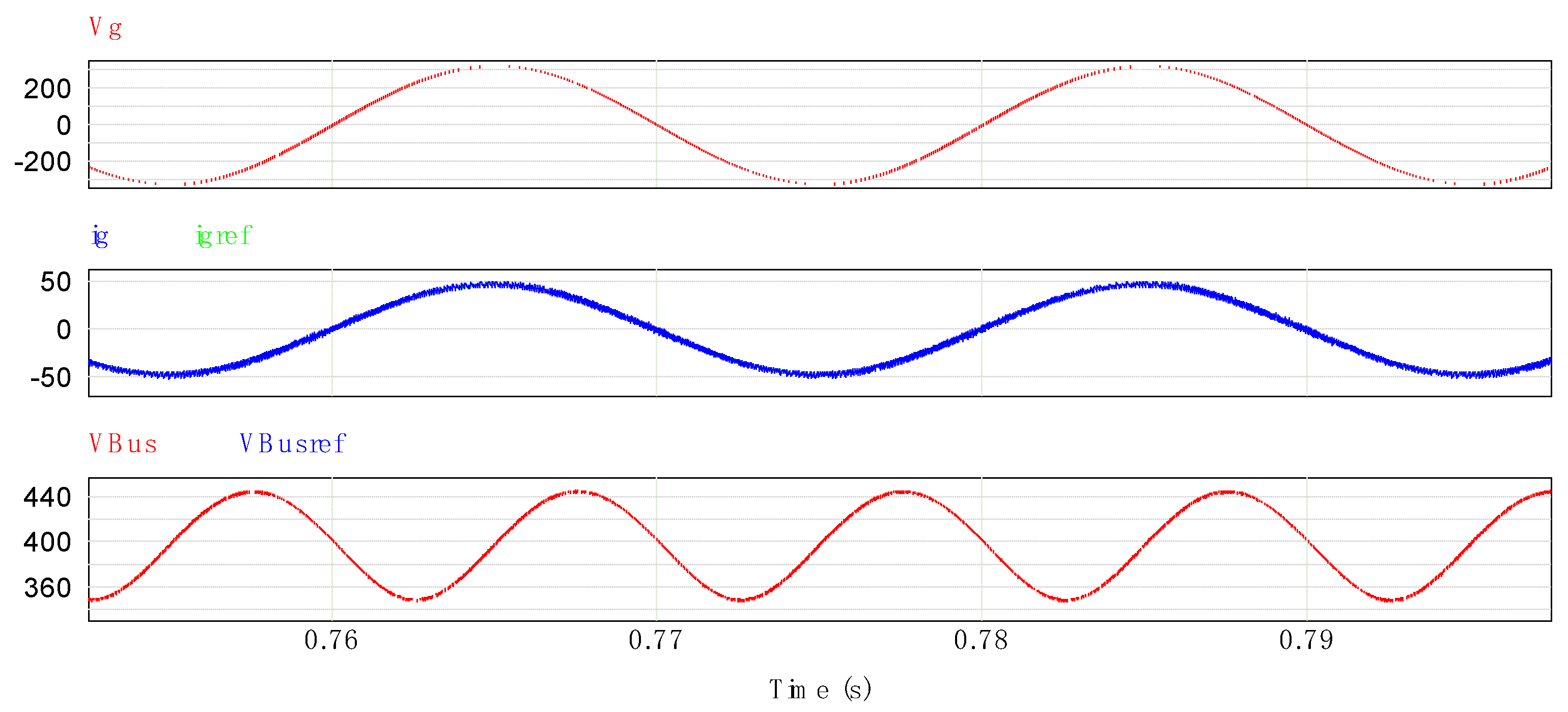
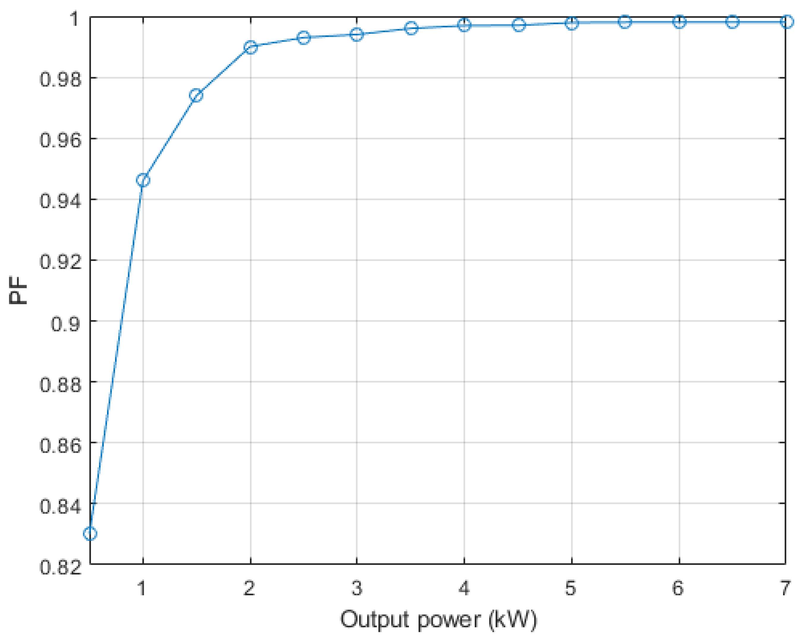
4. Simulation Results

4.1. Charge Simulations

Simulations were conducted in PSIM and MATLAB/Simulink environment using the parameters given in Table 4 and Table 5. Circuit components were simulated in PSIM and coupled with control algorithms running in MATLAB/Simulink.
Figure 5 shows the results in steady state for P Bat = 7 kW. The output voltage v Bus contains ripple voltage Δ   v Bus of about 96.5 V, which is 24% of the reference voltage.
In Figure 6, one cycle of the grid voltage v g and grid current i g is illustrated. i g is multiplied by 4 to increase its amplitude; it is close to the sinusoidal wave; therefore, the system draws power from the grid with a high power factor. It can be seen from Figure 7 that PF is higher than 0.8 at the light-load condition. It reaches 0.998 when the output power is higher than 6 kW.
Figure 5 shows results in steady state for P Bat = 7   kW . The output voltage contains ripple voltage of about 96.5 V, which is 24% of the reference voltage, and the grid current is illustrated, which is multiplied by 4 to increase its amplitude; it is close to the sinusoidal wave; therefore, the system draws power from the grid with a high power factor. It can be seen from Figure 7 that PF is higher than 0.8 at the light-load condition. It reaches 0.998 when the output power is higher than 6 kW. Figure 8, Figure 9 and Figure 10 show the responses of the system when P Bat is changed slightly from 1.5 kW to 7 kW. The rate of current reference is limited to four times less than V Bus / L b to ensure that the system can be adequately worked without any overshoot of the battery current, as shown in Figure 8. The waveform of battery current shows that the high-band width nonlinear current controller can effectively reject the ripple effect from v Bus .
From the results, the output voltage v Bus quickly returns to its reference after the change of the battery current, while the grid current is in good shape. A monotonic relationship between Δ v Bus and the grid current can be observed.

4.2. Electromagnetic Torque

In charge mode, one motor winding is reused as a line filter inductor, as shown in Figure 2. The input current passing through the winding may generate torque. While simple equations can be computed to quantify the electromagnetic torque, finite element analysis (FEA) gives more information on flux distribution and losses in the machine.
The first simulation in 2D FEA is realized with the hypothesis of sinusoidal current input of 32 Arms. Figure 11 shows the electromagnetic torque stabilized in 100 ms, where the average value is only 7.7 mNm. This torque level cannot move the electric motorcycle. The losses calculated in 2D FEA without taking into account the end winding are presented in Figure 12. Their values are very small. Thermal calculation is not necessary for this motor.
The second modeling of the machine in 2D FEA is done in a more realistic case. The harmonic 5 and 7 are taken into account in the input current. The results are shown in Figure 13, Figure 14 and Figure 15. The electromagnetic torque is stabilized for eight times longer than the first simulation with sinusoidal current input. Even with adding the current harmonics 5 and 7, the average electromagnetic steady-state torque is only 16 mNm, and the losses do not impact the thermal behavior of the machine.

5. Conclusions

An integrated charger-inverter (ICI) with an induction motor for high-performance electric motorcycle is proposed. To reduce the weight, volume, and cost, the main components are shared in drive and charge modes. The phase-A winding is used as an inductor for PFC using the first two legs of the three-phase inverter, while another leg is utilized to act as a charger with an additional inductor. The high bandwidth nonlinear controller rejects the double frequency ripple on the dc-link and allows the charger to adequately provide a constant current or constant voltage charging. The simulation results of 7 kW system validate the proposed system. Finite element analysis (FEA) determines the torque and losses of IM in charging mode and reveals that the torque productions are very small. It is notable to move the rotor. In addition, losses of the motor from the FEA results are low. Therefore, the proposed system can be implemented further.

Author Contributions

This article presents the collective work of all authors (V.T.T., M.P., and S.K.). All authors have read and agreed to the published version of the manuscript.

Funding

This work was funded in part by Hanoi University of Science and Technology (HUST) and King Mongkut University of Technology north of Bangkok, Thailand (grant number KMUTNB-63-KNOW-035).

Conflicts of Interest

The authors declare no conflict of interest.

References

  1. Drobnic, K.; Grandi, G.; Hammami, M.; Mandrioli, R.; Ricco, M.; Viatkin, A.; Vujacic, M. An Output Ripple-Free Fast Charger for Electric Vehicles Based on Grid-Tied Modular Three-Phase Interleaved Converters. IEEE Trans. Ind. Appl. 2019, 55, 6102–6114. [Google Scholar] [CrossRef]
  2. Patil, D.; Agarwal, V. Compact Onboard Single-Phase EV Battery Charger with Novel Low-Frequency Ripple Compensator and Optimum Filter Design. IEEE Trans. Ind. Appl. 2016, 65, 1948–1956. [Google Scholar] [CrossRef]
  3. Shi, C.; Tang, Y.; Khaligh, A. A Three-Phase Integrated Onboard Charger for Plug-In Electric Vehicles. IEEE Trans. Power Electron. 2018, 33, 4716–4725. [Google Scholar] [CrossRef]
  4. Hatti, N.; Nuilers, S.; Chayopitak, N.; Somsiri, P. An integrated battery charger configuration for SRM drive in electric motorcycles. IEEJ Trans. Electr. Electron. Eng. 2018, 13, 295–302. [Google Scholar] [CrossRef]
  5. Subotic, I.; Bodo, N.; Levi, E. Single-Phase On-Board Integrated Battery Chargers for EVs Based on Multiphase Machines. IEEE Trans. Power Electron. 2016, 31, 6511–6523. [Google Scholar] [CrossRef] [Green Version]
  6. Shi, C.; Tang, Y.; Khaligh, A. A Single-Phase Integrated Onboard Battery Charger Using Propulsion System for Plug-in Electric Vehicles. IEEE Trans. Veh. Technol. 2017, 66, 10899–10910. [Google Scholar] [CrossRef]
  7. Cheng, H.; Wang, Z.; Yang, S.; Huang, J.; Ge, X. An Integrated SRM Powertrain Topology for Plug-In Hybrid Electric Vehicles with Multiple Driving and Onboard Charging Capabilities. IEEE Trans. Transp. Electrif. 2020, 6, 578–591. [Google Scholar] [CrossRef]
  8. Bodo, N.; Levi, E.; Subotic, I.; Espina, J.; Empringham, L.; Johnson, C.M. Efficiency Evaluation of Fully Integrated On-Board EV Battery Chargers with Nine-Phase Machines. IEEE Trans. Energy Convers. 2017, 32, 257–266. [Google Scholar] [CrossRef]
  9. Metwly, M.Y.; Abdel-Majeed, M.S.; Abdel-Khalik, A.S.; Hamdy, R.A.; Hamad, M.S.; Ahmed, S. A Review of Integrated On-Board EV Battery Chargers: Advanced Topologies, Recent Developments and Optimal Selection of FSCW Slot/Pole Combination. IEEE Access 2020, 8, 85216–85242. [Google Scholar] [CrossRef]
  10. Kataoka, R.; Shichi, A.; Yamada, H.; Iwafune, Y.; Ogimoto, K. Comparison of the Economic and Environmental Performance of V2H and Residential Stationary Battery: Development of a Multi-Objective Optimization Method for Homes of EV Owners. World Electr. Veh. J. 2019, 10, 78. [Google Scholar] [CrossRef] [Green Version]
  11. Subotic, I.; Jones, M.; Levi, E. A fast on-board integrated battery charger for four-motor EVs. In Proceedings of the 2014 International Conference on Electrical Machines (ICEM), Berlin, Germany, 2–5 September 2014; pp. 2066–2072. [Google Scholar]
  12. Thimmesch, D. An SCR inverter with an integral battery charger for electric vehicles. IEEE Trans. Ind. Appl. 1985, IA-21, 1023–1029. [Google Scholar] [CrossRef]
  13. Tang, L.; Su, G.-J. Control scheme optimization for a low-cost, digitally-controlled charger for plug-in hybrid electric vehicles. In Proceedings of the 2010 IEEE Energy Conversion Congress and Exposition, Atlanta, GA, USA, 12–16 September 2010; pp. 3604–3610. [Google Scholar]
  14. Matsuhashi, D.; Matsuo, K.; Okitsu, T.; Ashikaga, T.; Mizuno, T. Comparison study of various motors for EVs and the potentiality of a ferrite magnet motor. IEEJ J. Ind. Appl. 2015, 4, 173–179. [Google Scholar] [CrossRef] [Green Version]
  15. Tuan, V.T.; Kreuawan, S.; Somsiri, P.; Tungpimolrut, K.; Huy, P.N. Switched Reluctance Motor and Induction Machine for E-Scooter Based on Driving Cycles Design Comparisons. IEEJ Trans. Electr. Electron. Eng. 2020, 15, 931–938. [Google Scholar] [CrossRef]
  16. Vosswinkel, M.; Lohner, A.; Platte, V.; Hirche, T. Design, Production, and Verification of a Switched-Reluctance Wheel Hub Drive Train for Battery Electric Vehicles. World Electr. Veh. J. 2019, 10, 82. [Google Scholar] [CrossRef] [Green Version]
  17. Na, T.; Zhang, Q.; Tang, J.; Wang, J. Active power filter for single-phase Quasi-Z-source integrated on-board charger. CPSS Trans. Power Electron. Appl. 2018, 3, 197–201. [Google Scholar] [CrossRef]
  18. Xiao, Y.; Liu, C.; Yu, F. An Effective Charging-Torque Elimination Method for Six-Phase Integrated On-Board EV Chargers. IEEE Trans. Power Electron. 2020, 35, 2776–2786. [Google Scholar] [CrossRef]
  19. Gavagsaz-Ghoachani, R.; Saublet, L.; Phattanasak, M.; Martin, J.; Nahid-mobarakeh, B.; Pierfederici, S. Active stabilisation design of DC–DC converters with constant power load using a sampled discrete-time model: Stability analysis and experimental verification. IET Power Electron. 2018, 11, 1519–1528. [Google Scholar] [CrossRef]
  20. Gavagsaz-Ghoachani, R.; Phattanasak, M.; Martin, J.; Nahid-Mobarakeh, B.; Pierfederici, S. A Fixed-Frequency Optimization of PWM Current Controller—Modeling and Design of Control Parameters. IEEE Trans. Transp. Electrif. 2018, 4, 671–683. [Google Scholar] [CrossRef]
  21. Das, P.; Pahlevaninezhad, M.; Moschopoulos, G. Analysis and Design of a New AC–DC Single-Stage Full-Bridge PWM Converter with Two Controllers. IEEE Trans. Ind. Electron. 2013, 60, 4930–4946. [Google Scholar] [CrossRef]
  22. Ferrieux, J.P.; Forest, F. Alimentations à Découpage Convertisseurs à Résonance, 3rd ed.; Dunod: Malakoff, France, 2006. [Google Scholar]
  23. Nussbaumer, T.; Raggl, K.; Kolar, J.W. Design Guidelines for Interleaved Single-Phase Boost PFC Circuits. IEEE Trans. Ind. Electron. 2009, 56, 2559–2573. [Google Scholar] [CrossRef]
  24. Shenai, K. WBG Power Converters for Hybrid & EV Applications. Auto Tech. Rev. 2016, 5, 42–47. [Google Scholar]
  25. Robert, E.; Dragan, M.; Khurram, A.; David, J.; Daniel, F.; Hyeokjin, K.; Usama, A.; Jianglin, Z.; Kraig, O.; Brandon, P.; et al. A Disruptive Approach to Electric Vehicle Power Electronics Final Report; Univ. of Colorado: Boulder, CO, USA, 2017. [Google Scholar]
Figure 1. Integrated charger-inverter (ICI) topology in drive mode.
Wevj 12 00019 g001
Figure 2. ICI topology in charge mode. PFC, power factor correction.
Wevj 12 00019 g002
Figure 3. PFC control block diagram.
Wevj 12 00019 g003
Figure 4. Charger control block diagram. CC, constant current; CV, constant voltage.
Wevj 12 00019 g004
Figure 5. DC link voltage without active filter for P Bat = 7   kW .
Wevj 12 00019 g005
Figure 6. Input current waveform for P Bat = 7   kW .
Wevj 12 00019 g006
Figure 7. Power factor (PF) for different levels of output power.
Wevj 12 00019 g007
Figure 8. Battery current waveform for P Bat = 1.5   kW 7   kW .
Wevj 12 00019 g008
Figure 9. DC link voltage without an active filter P Bat = 1.5   kW 7   kW .
Wevj 12 00019 g009
Figure 10. Input current waveform for P Bat = 1.5   kW 7   kW .
Wevj 12 00019 g010
Figure 11. Electromagnetic torque with 32 A sinusoidal current input.
Wevj 12 00019 g011
Figure 12. Losses of induction motor in 2D finite element analysis (FEA).
Wevj 12 00019 g012
Figure 13. Electromagnetic torque with 32 A harmonic current.
Wevj 12 00019 g013
Figure 14. Losses in 2D FEA with harmonic current.
Wevj 12 00019 g014
Figure 15. Flux circulation of induction motor (IM) in charge mode.
Wevj 12 00019 g015
Table 1. On-board charger (OBC) parameters.
Manufacturer/ReferenceSpecific Power (kW/kg)Power Density (kW/L)Cost Per kW (USD/kW)
2012 Nissan Leaf 6.6 kW OBC [24]0.410.66N/A
Tier one OBC 3.3 kW [24]N/AN/A83
Eton (1)N/A2N/A
Ovartech 6.6 kW Water-cool (2)1.10.61N/A
Table 2. Additional components of the proposed integrated charger-inverter 7 kW.
Manufacturer/ReferenceWeight (kg)Volume (L)Cost (USD)
S2 (40 A, 450 V DC contactor) (3)0.150.1130
S3 (10 A, 250 Vac 3-pole relay) (4)0.030.0210
Lb (estimated)10.530
Co (3 uF, 450 V) (5)0.00850.00745
Total1.190.6475
Table 3. Integrated charger-inverter (ICI) parameters.
Manufacturer/ReferenceSpecific Power (kW/kg)Power Density (kW/L)Cost Per kW (USD/kW)
Proposed ICI 7.7 kW5.8810.9310.71
ICI 6.6 kW from [25]4N/AN/A
Table 4. Converter parameters. PFC, power factor correction.
Parameters (Unit)
Grid voltage, V g 230 Vrms
Grid frequency, f grid 50 Hz
Switching frequency, f s 20 kHz
Output voltage, V Bus 400 V
Maximum battery power, p Bat 7 kW
PFC inductor L a , r a (phase a winding)1.3 mH, 0.015 Ω
Charger inductor L b , r b (additional inductor)10 mH, 0.015 Ω
Capacitor, C Bus 640 μF
Capacitor, C o 2.2 μF
Battery full voltage of 48 cells201.6 V
Table 5. Control parameters.
Parameters (Unit)
PFC
-  K P , T i 0.11, 0.5 ms
-  ξ , ω n 0.707, 150 rad/s
-  K 1 ,   K 2 212.10, 22,500
Charger
-  λ = K i 2 π f s / 10 rad/s
-  K P , T i 0.01, 0.1 s
Publisher’s Note: MDPI stays neutral with regard to jurisdictional claims in published maps and institutional affiliations.

