Comparative Study of Dual PM Vernier Machines


Abstract
:1. Introduction
2. Machine Topologies and Working Principle
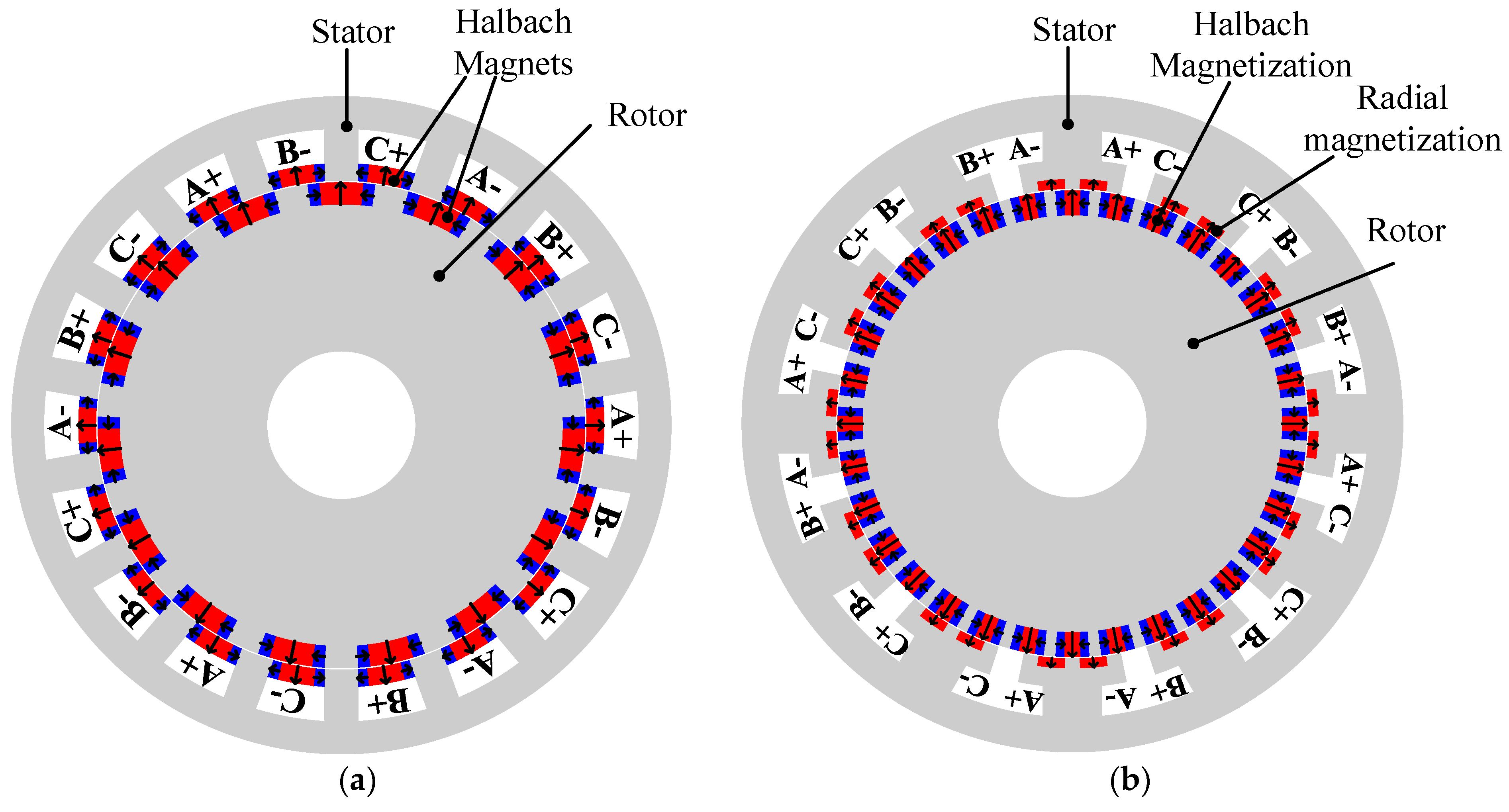
2.1. Machine Topology
2.2. Working Principle
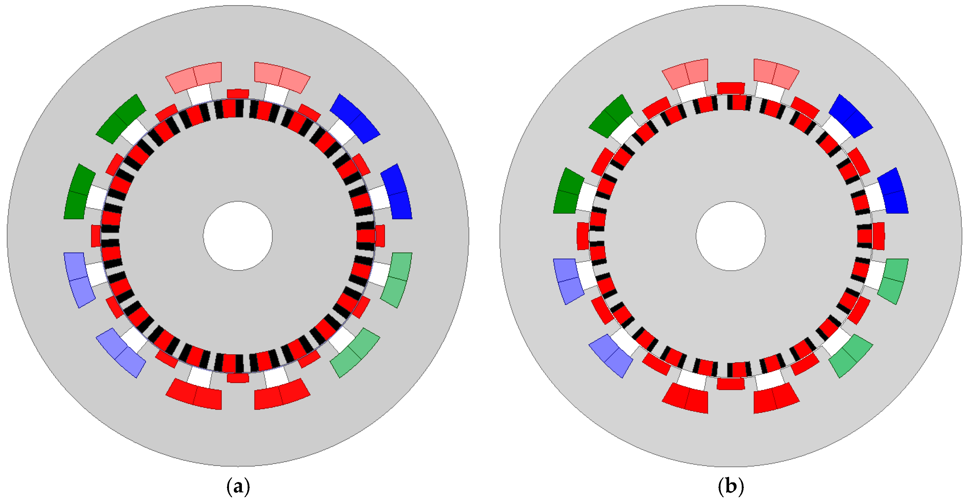
3. Influence of Rotor Slot Number
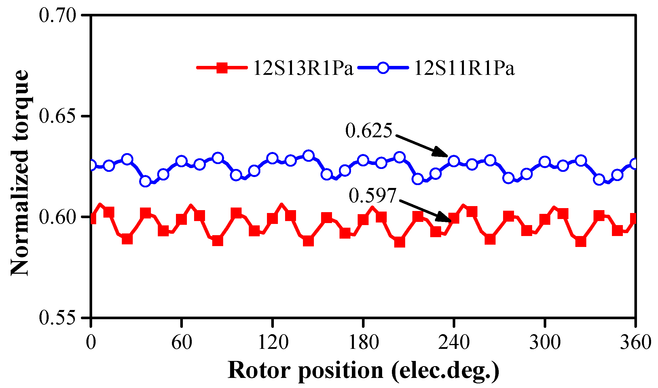
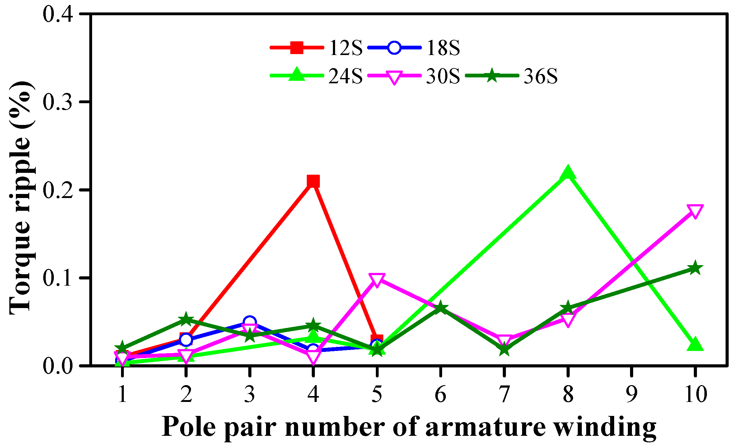
4. Influence of Different Slot/Pole Number Combinations
- (a)
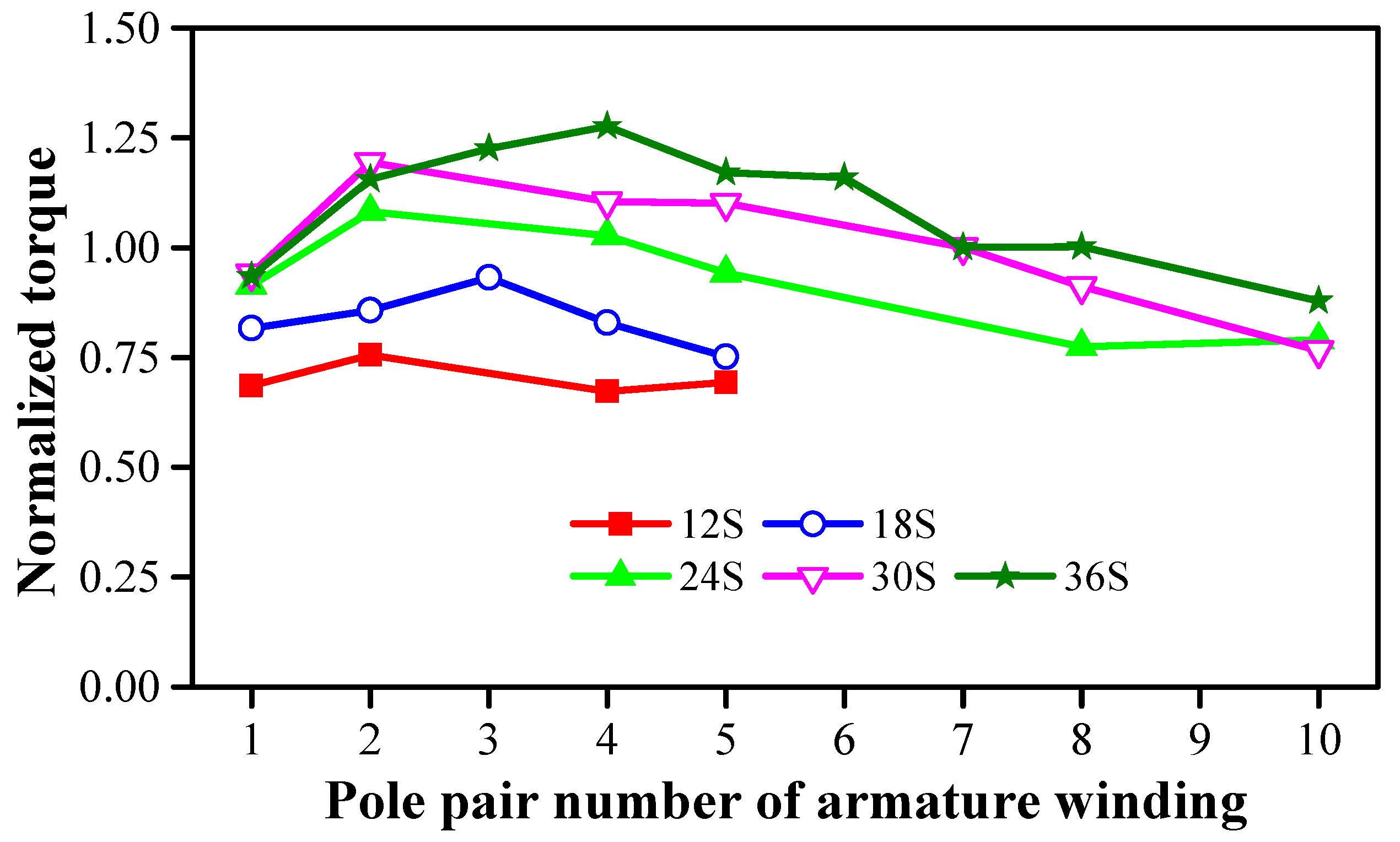
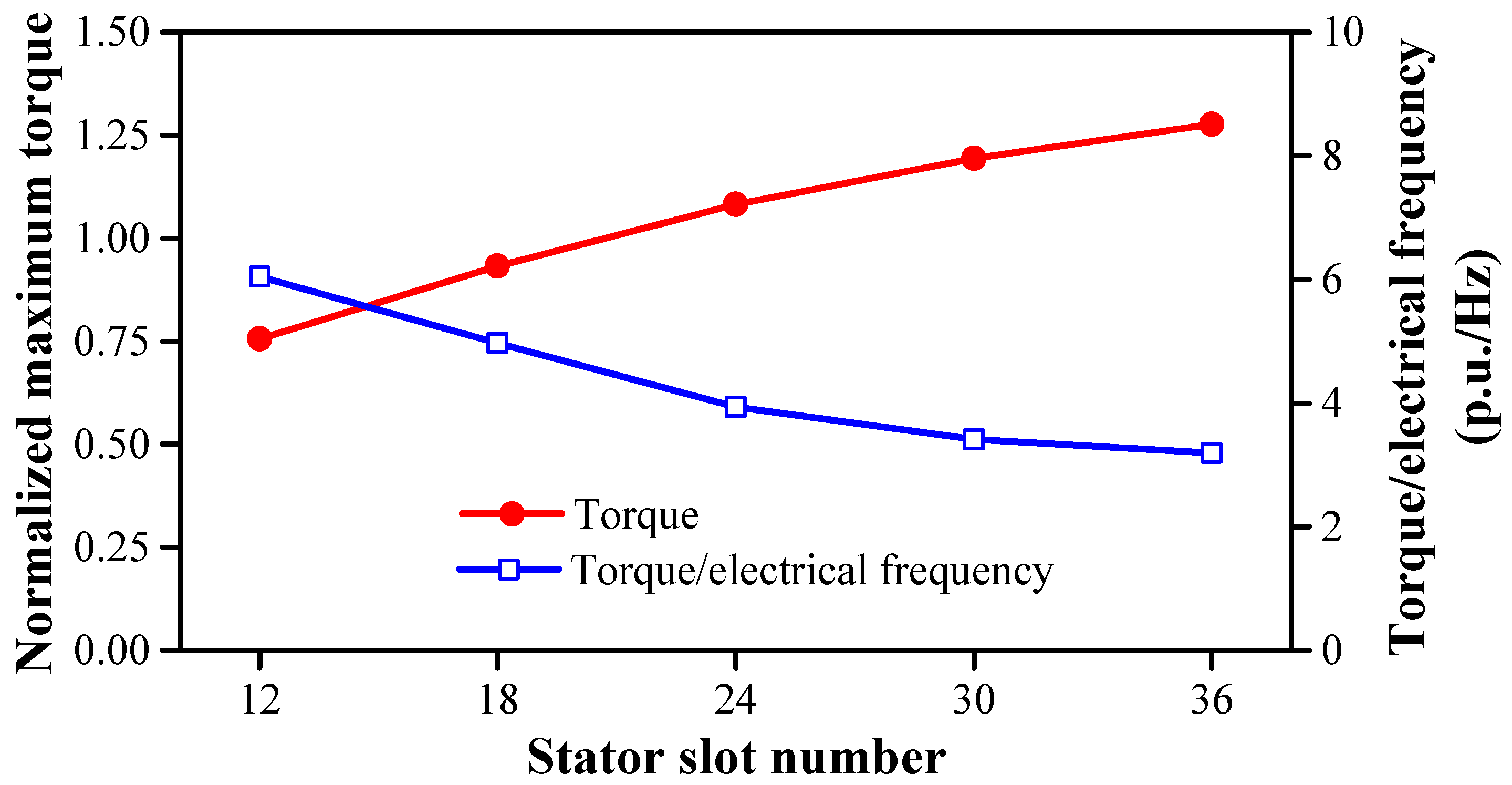
- The increase of electrical frequency significantly affects other indexes, e.g., increasing the losses, decreasing the power factor, increasing the carrier frequency. All of these will deteriorate the overall performances. Figure 12 shows that the torque/electrical frequency decreases with the increase of stator slot number.
- (b)
- The maximum torque increase rate decreases. When increasing the stator slot number from 12 to 18, the maximum torque increases by 0.176 p.u. However, when the stator slot number increases from 30 to 36, the maximum torque increases by 0.08 p.u. Hence, it is not cost-effective to further increase the stator slot number.
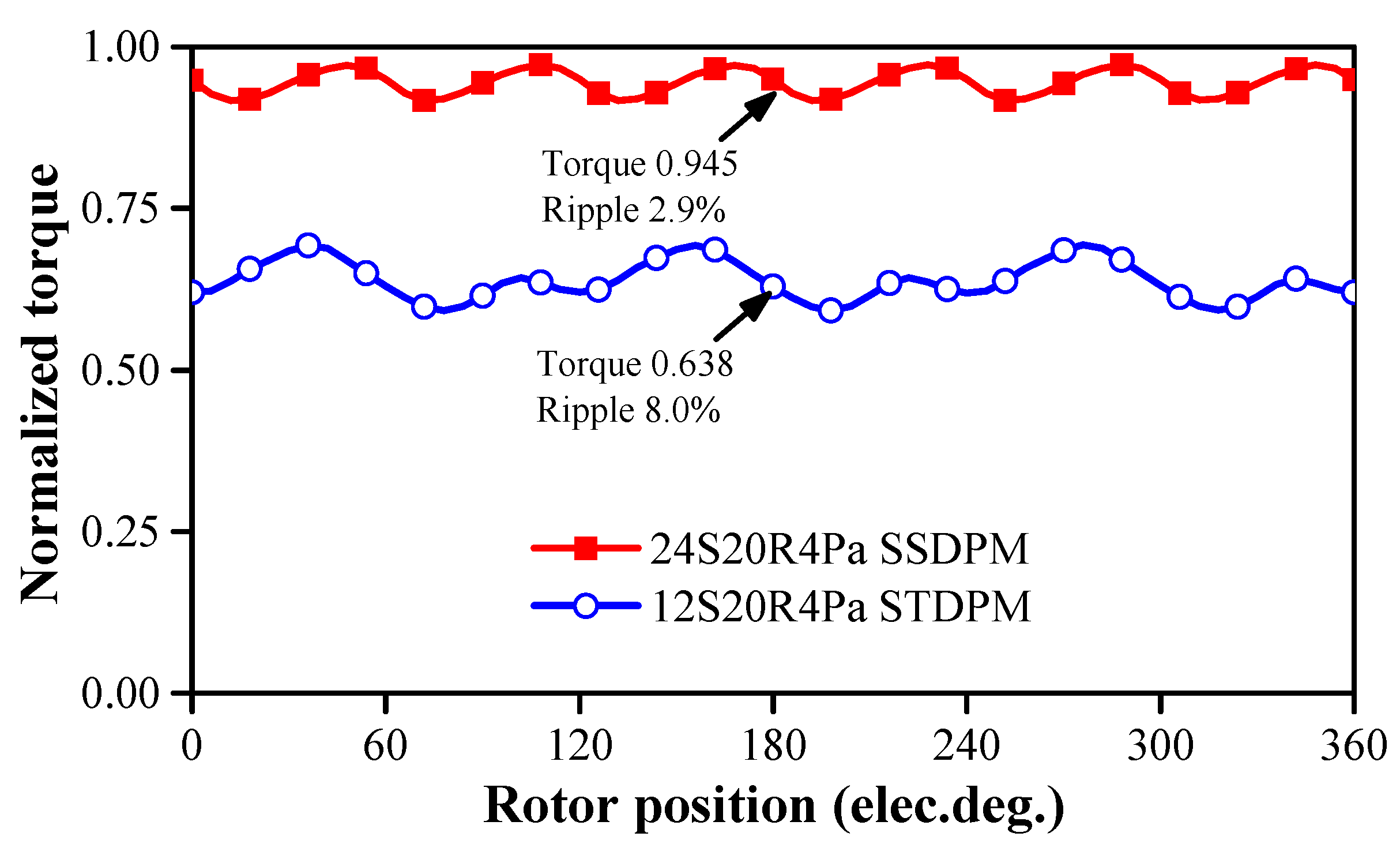
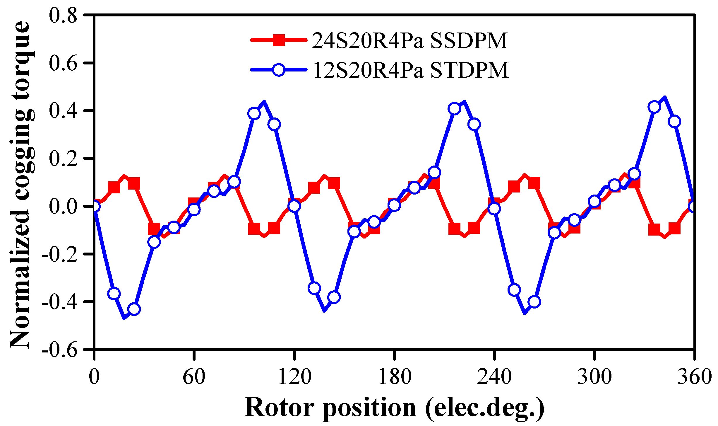
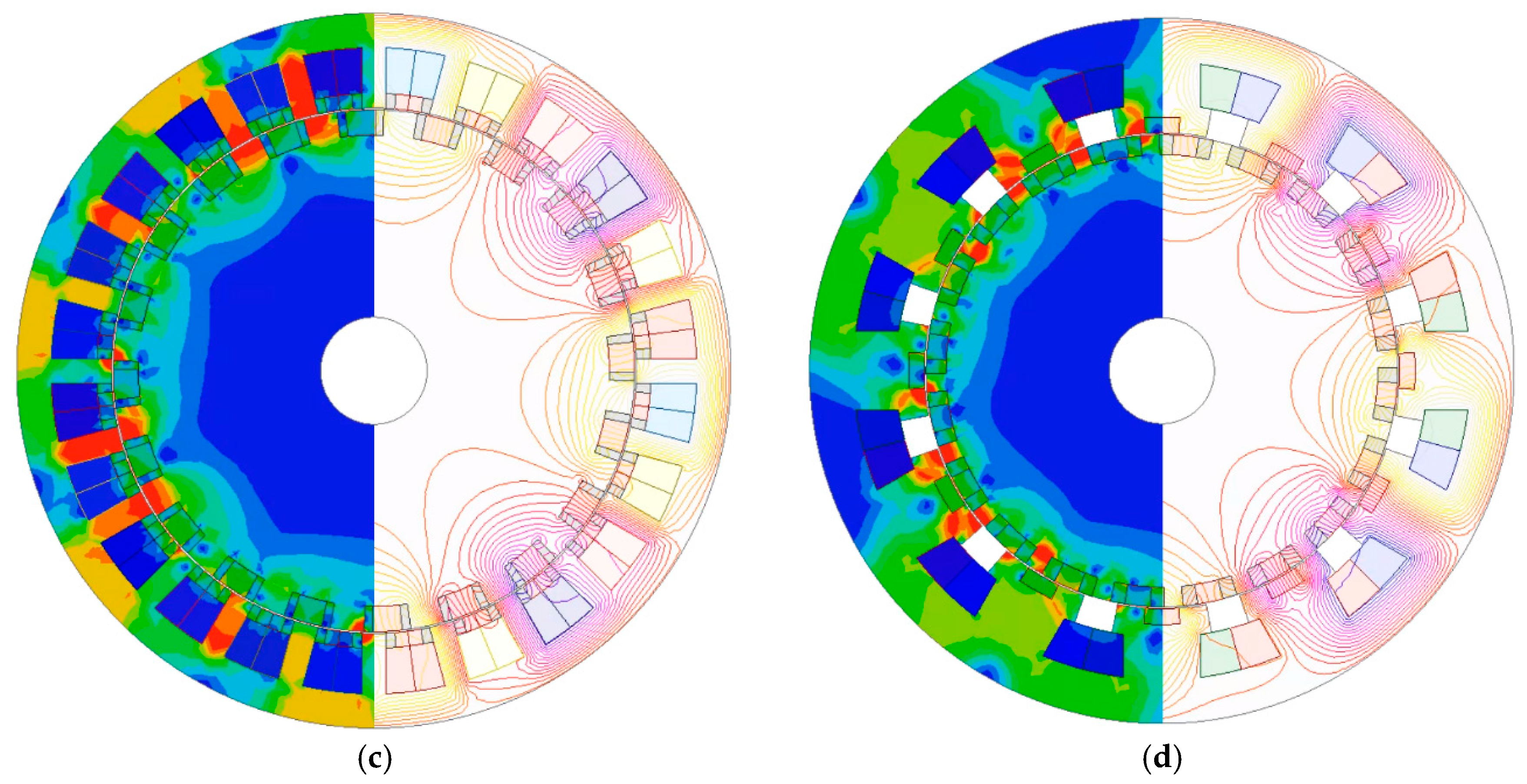
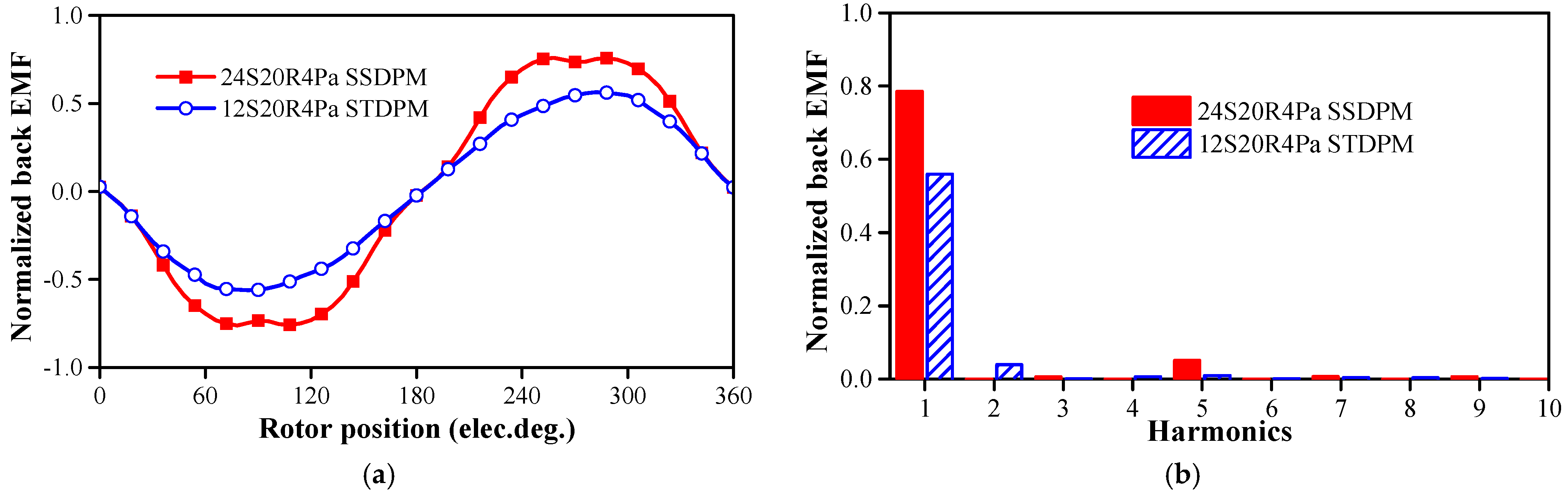
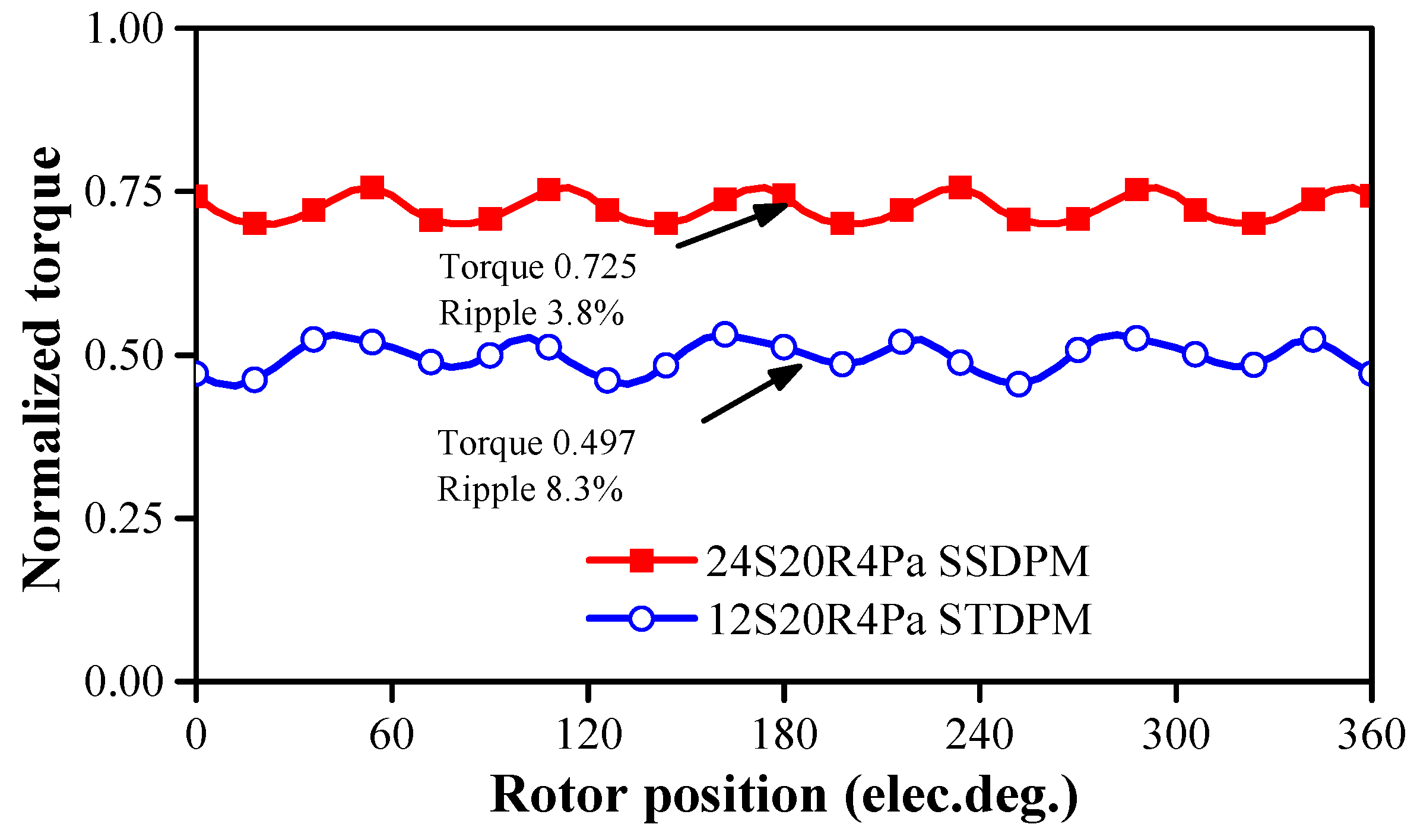
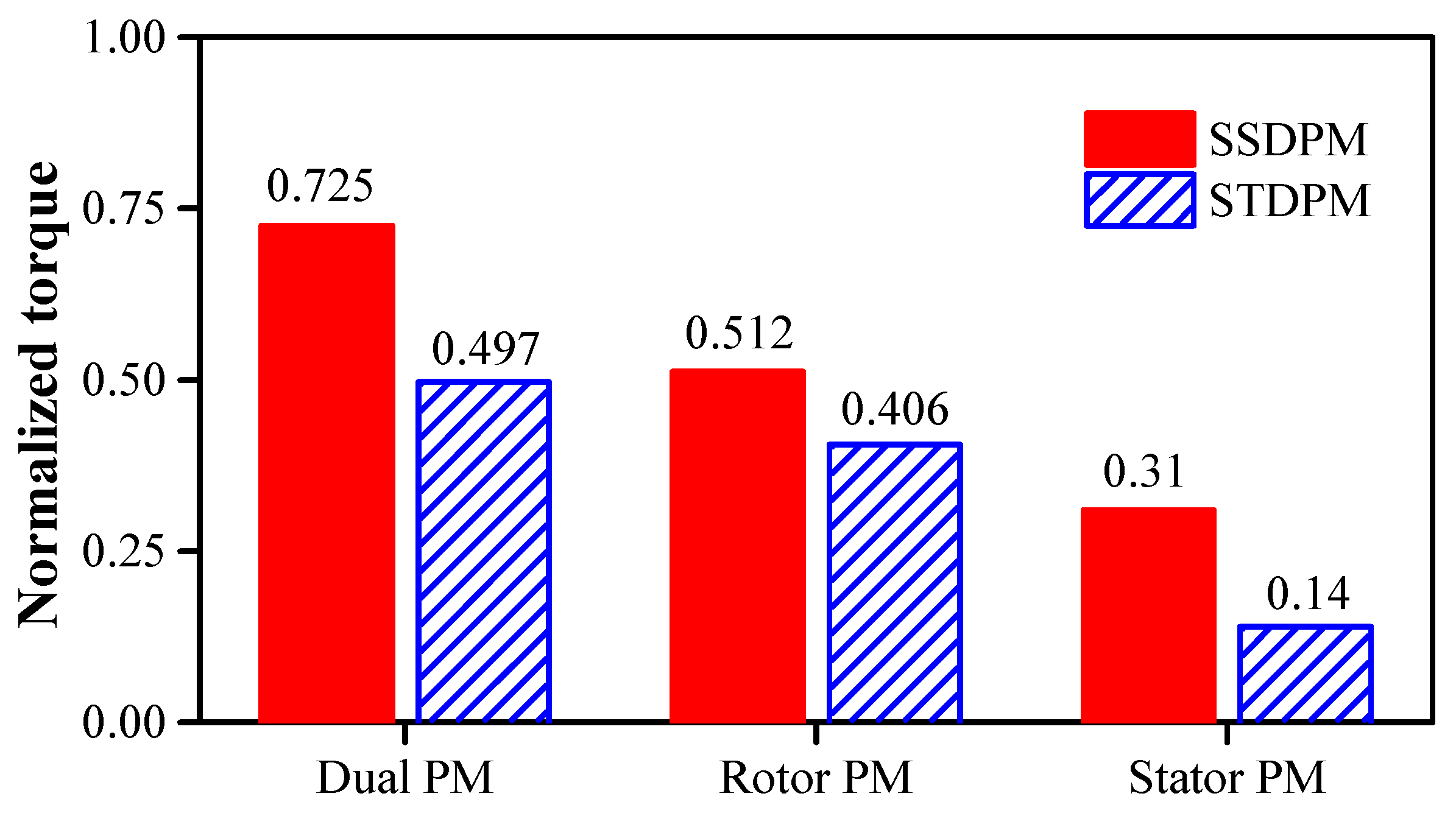
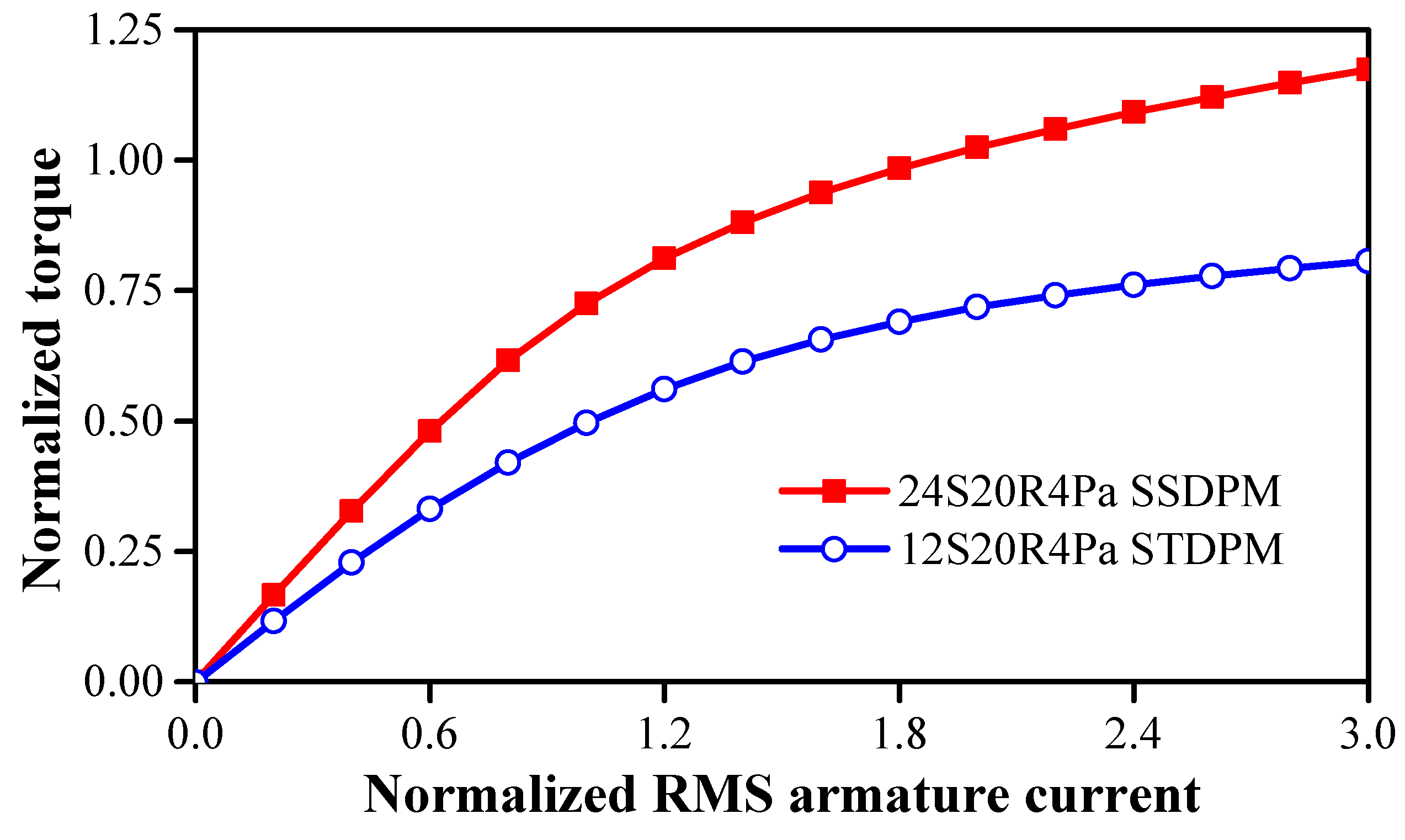
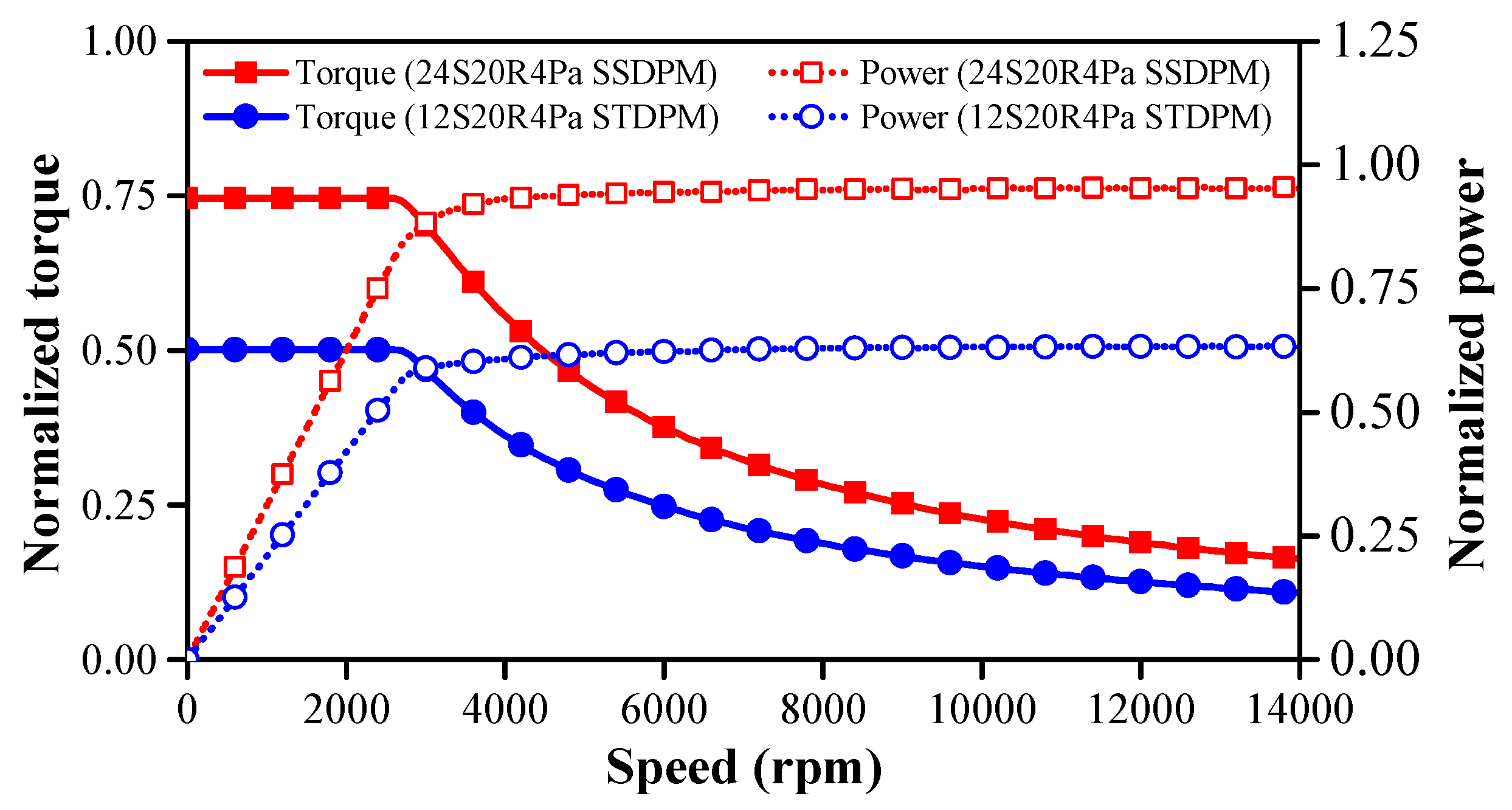
5. Comparison of Stator Slot Dual-PM Machine and Split Tooth Dual-PM Machine
6. Conclusions
- (a)
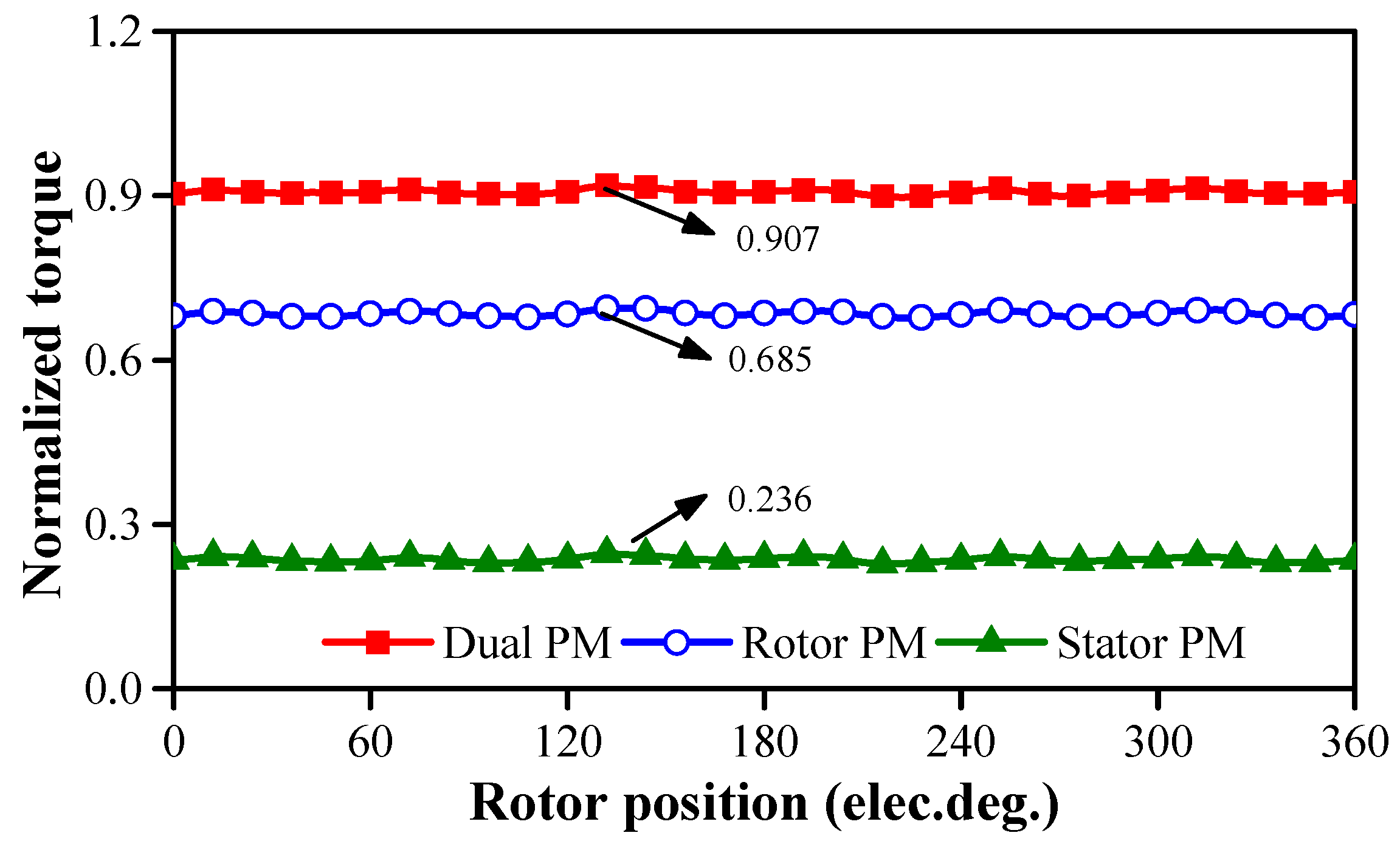
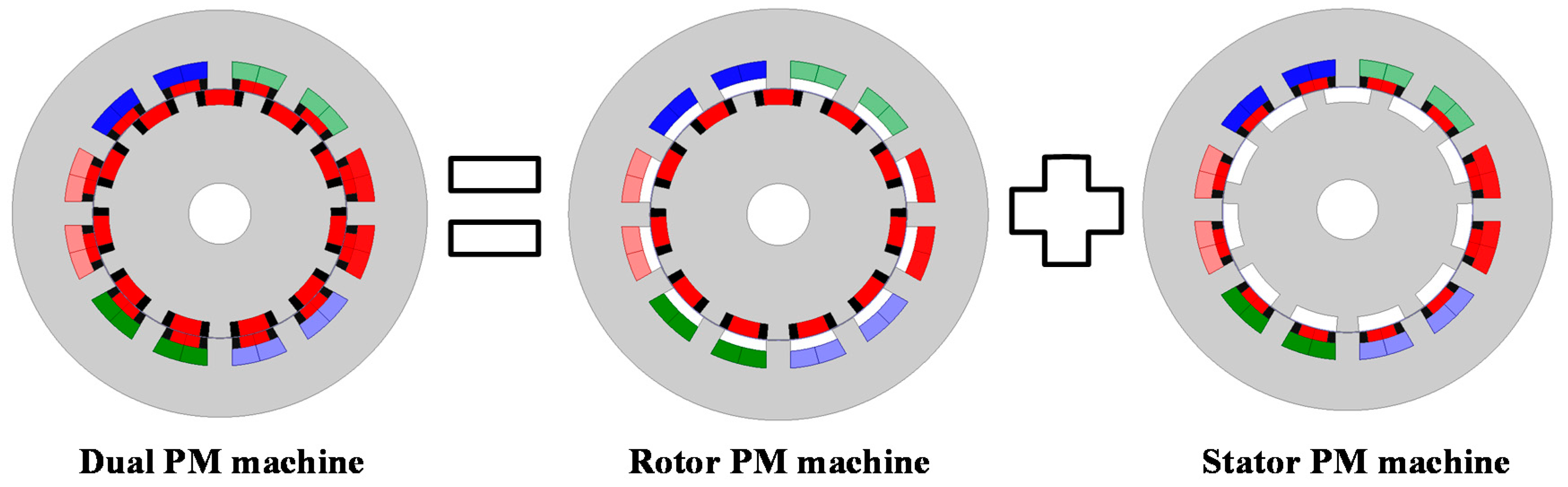
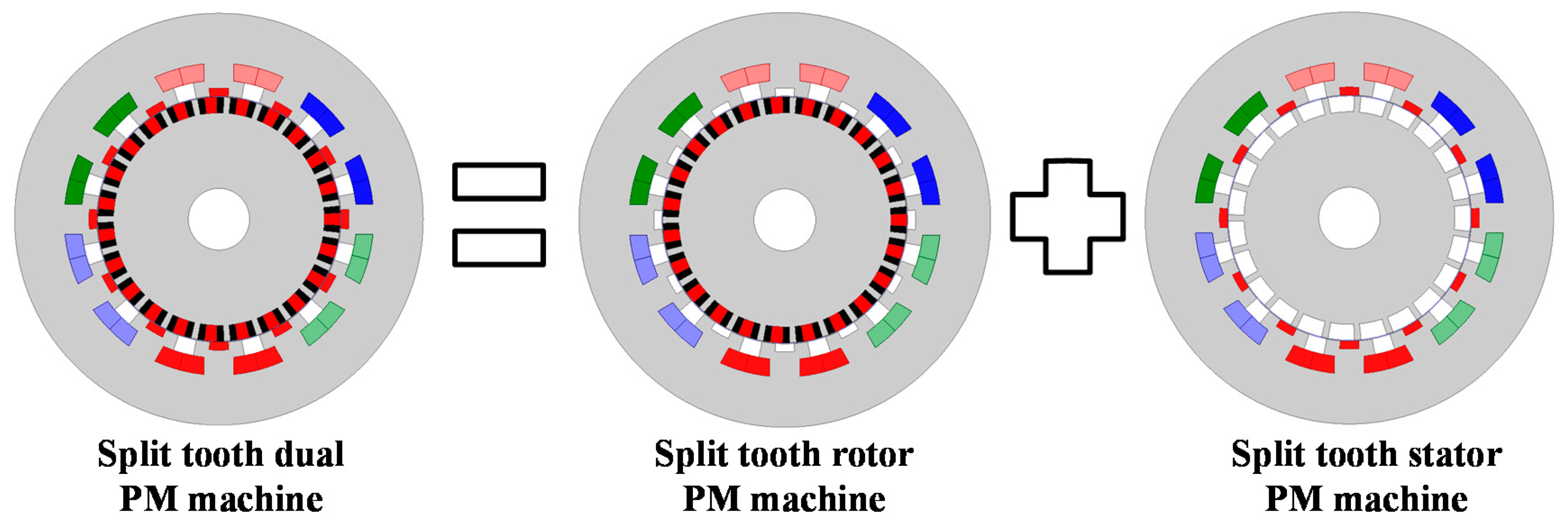
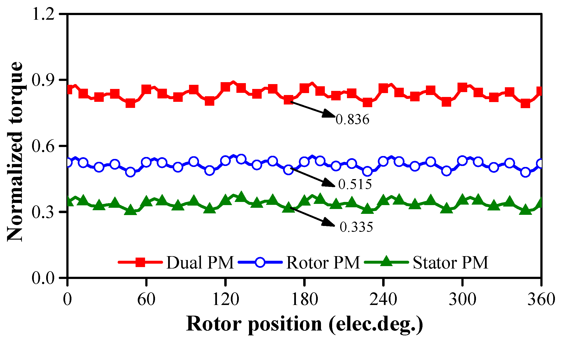
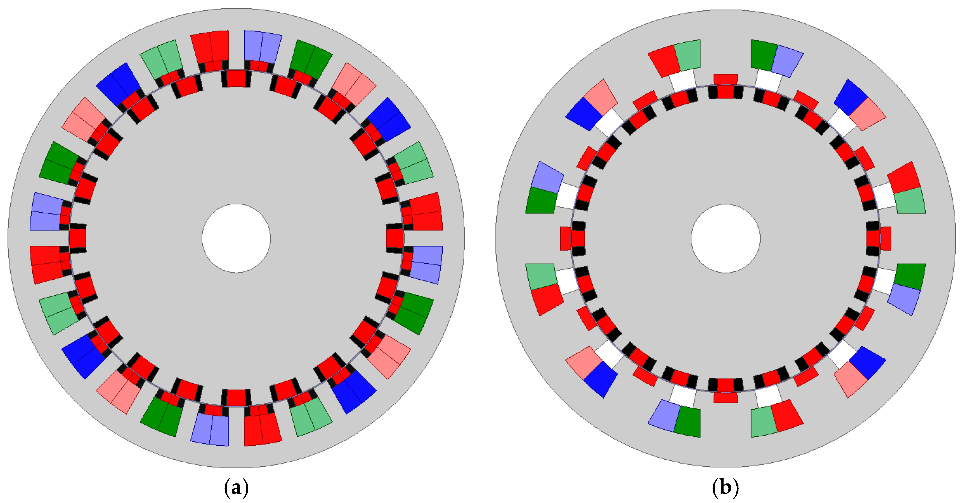
- Dual-PM machines can be decomposed into stator PM machines and rotor PM machines that share the same slot/pole number combinations.
- (b)
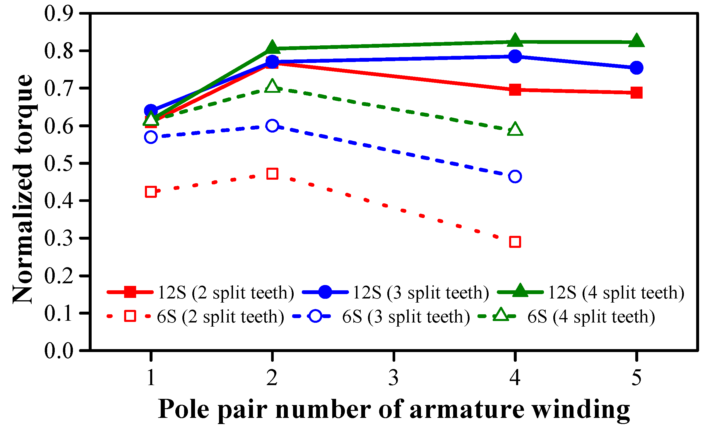
- There exists one optimum armature pole pair number for maximum torque.
- (c)
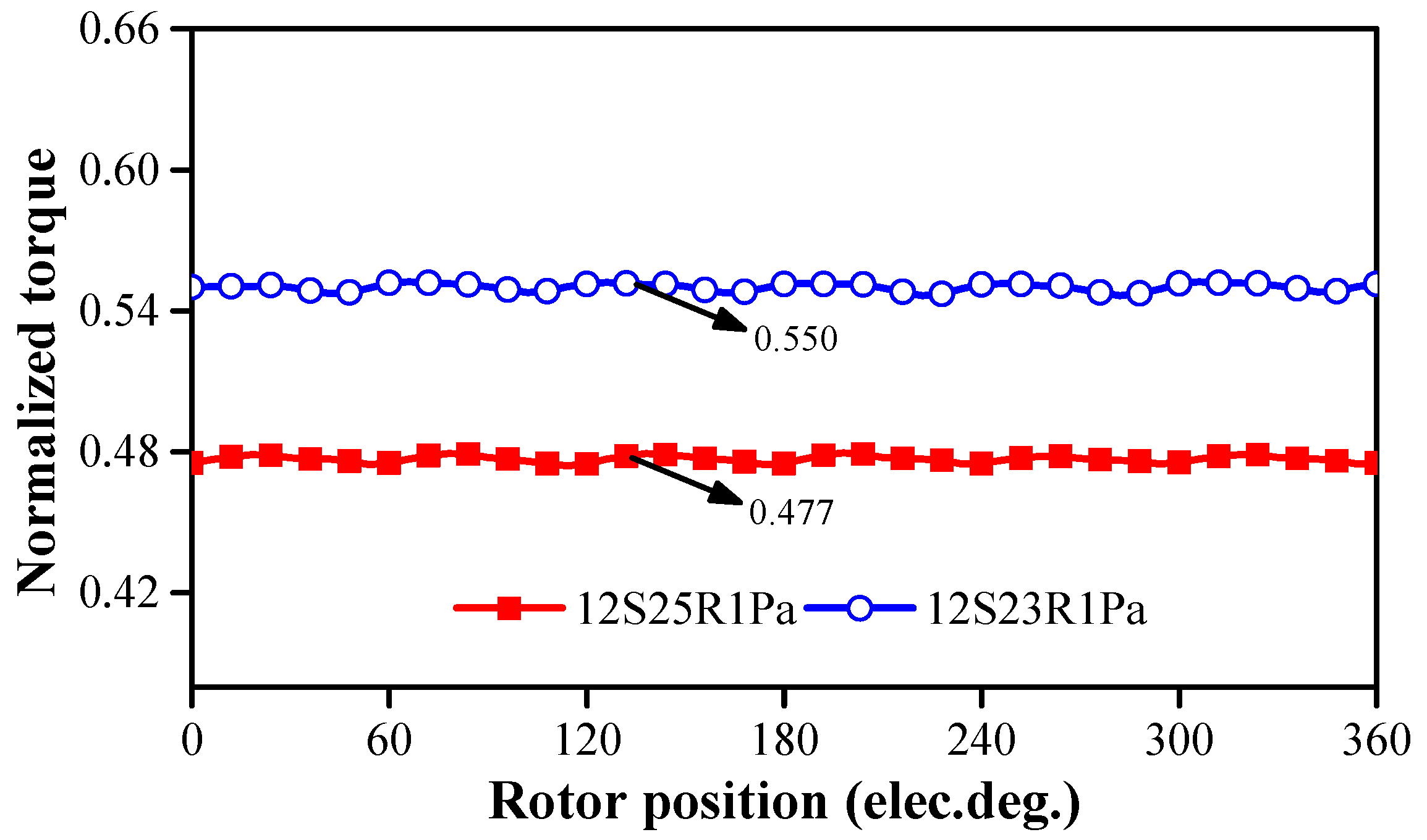
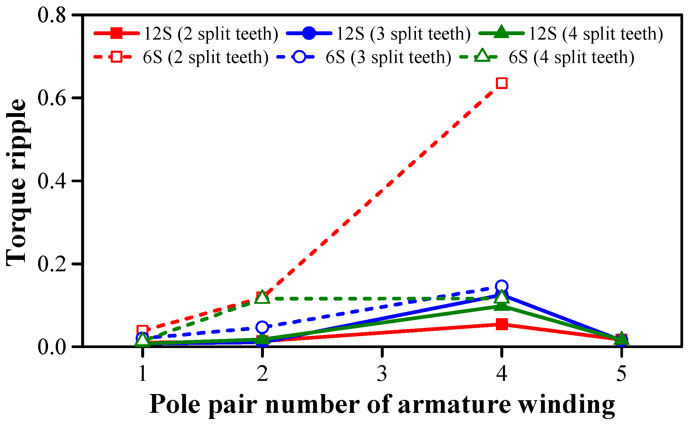
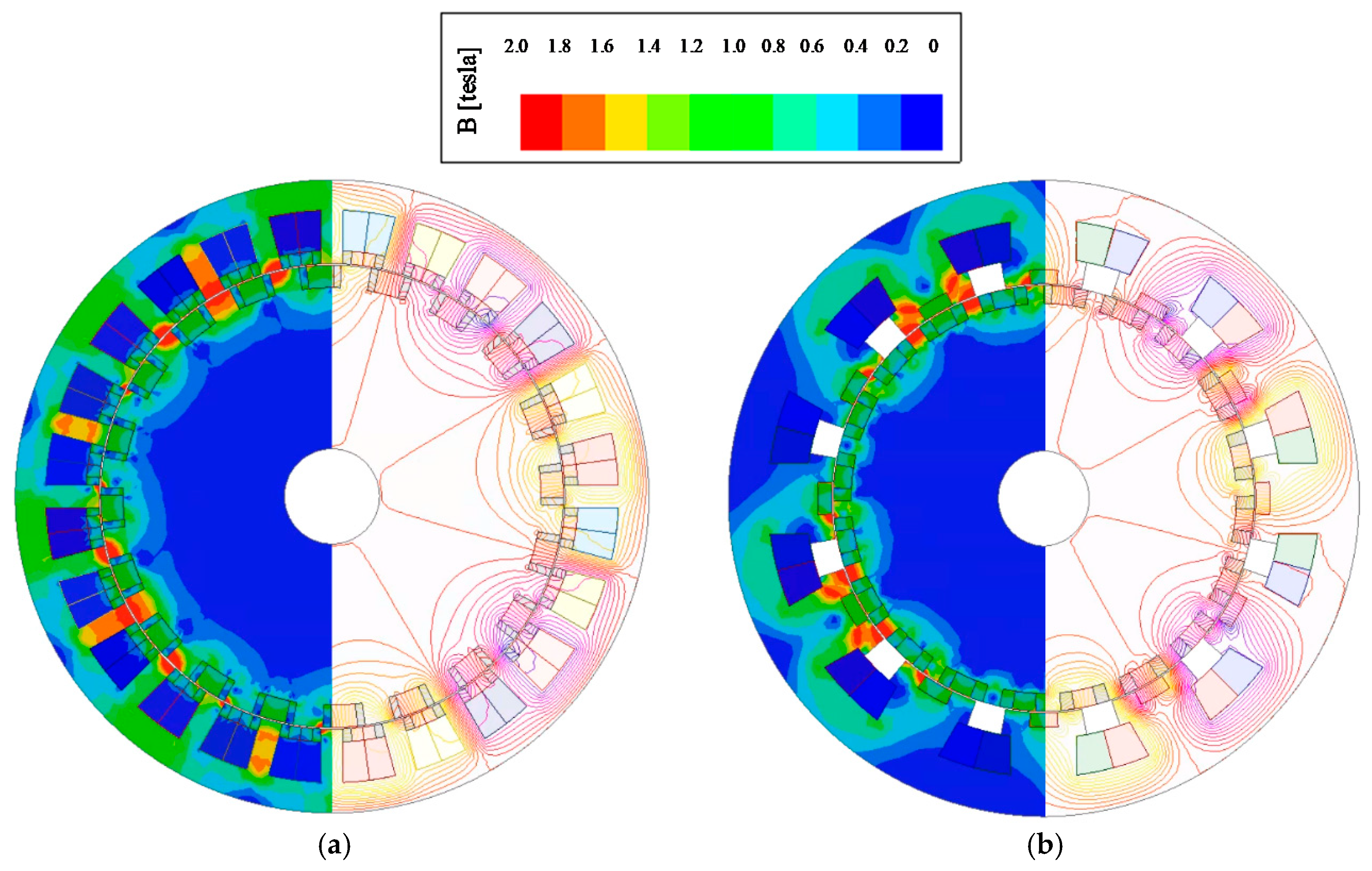
- The SSDPM machines exhibits better electromagnetic performances than the STDPM machines.
Author Contributions
Funding
Data Availability Statement
Conflicts of Interest
Nomenclature
| µr | Relative permeability of PM material |
| Br | Remanence of PM material |
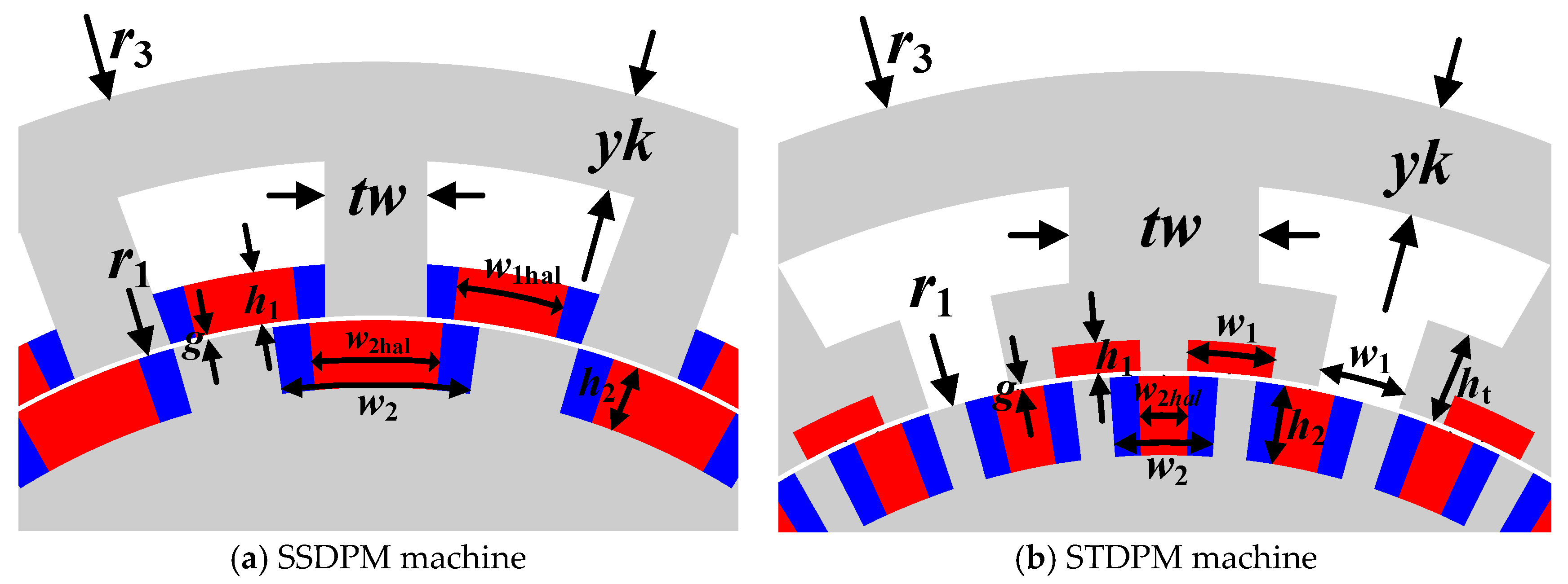
| g | Airgap length |
| h1 | Stator PM height |
| h2 | Rotor PM height |
| ht | Tooth tip height |
| lstk | Stack length |
| r1 | Rotor outer radius |
| r3 | Stator outer radius |
| tw | Stator tooth width |
| Sslot | Slot area |
| w1 | Stator PM width |
| w1hal | Width of radially magnetized PM in stator Halbach PM array |
| w2 | Rotor PM width |
| w2hal | Width of radially magnetized PM in rotor Halbach PM array |
| yk | Stator yoke width |
| Imax | Amplitude of maximum current |
| Id | D-axis current |
| Iq | Q-axis current |
References
- Atallah, K.; Rens, J.; Mezani, S.; Howe, D. A Novel “Pseudo” Direct-Drive Brushless Permanent Magnet Machine. IEEE Trans. Magn. 2008, 44, 4349–4352. [Google Scholar] [CrossRef]
- Cooke, G.; Atallah, K. “Pseudo” Direct Drive Electrical Machines with Alternative Winding Configurations. IEEE Trans. Magn. 2017, 53, 1–8. [Google Scholar] [CrossRef]
- Penzkofer, A.; Atallah, K. Analytical Modeling and Optimization of Pseudo-Direct Drive Permanent Magnet Machines for Large Wind Turbines. IEEE Trans. Magn. 2015, 51, 1–14. [Google Scholar] [CrossRef]
- Li, D.; Qu, R.; Lipo, T.A. High-Power-Factor Vernier Permanent-Magnet Machines. IEEE Trans. Ind. Appl. 2014, 50, 3664–3674. [Google Scholar] [CrossRef]
- Ishizaki, A.; Tanaka, T.; Takasaki, K.; Nishikata, S. Theory and optimum design of PM Vernier motor. In Proceedings of the International Conference on Electrical Machines and Drives, Durham, UK, 11–13 September 1995; pp. 208–212. [Google Scholar]
- Wu, Z.Z.; Zhu, Z.Q. Analysis of Air-Gap Field Modulation and Magnetic Gearing Effects in Switched Flux Permanent Magnet Machines. IEEE Trans. Magn. 2015, 51, 1–12. [Google Scholar] [CrossRef]
- Qu, R.; Li, D.; Wang, J. Relationship between magnetic gears and vernier machines. In Proceedings of the International Conference on Electrical Machines and Systems, Beijing, China, 20–23 August 2011; pp. 1–6. [Google Scholar]
- Wu, Z.Z.; Zhu, Z.Q. Analysis of Magnetic Gearing Effect in Partitioned Stator Switched Flux PM Machines. IEEE Trans. Energy Convers. 2016, 31, 1239–1249. [Google Scholar] [CrossRef]
- Chen, Y.; Fu, W.; Weng, X. A Concept of General Flux-Modulated Electric Machines Based on a Unified Theory and Its Application to Developing a Novel Doubly-Fed Dual-Stator Motor. IEEE Trans. Ind. Electron. 2017, 64, 9914–9923. [Google Scholar] [CrossRef]
- Cheng, M.; Chau, K.; Chan, C. Static characteristics of a new doubly salient permanent magnet motor. IEEE Trans. Energy Convers. 2001, 16, 20–25. [Google Scholar] [CrossRef] [Green Version]
- Chen, J.T.; Zhu, Z.Q. Winding Configurations and Optimal Stator and Rotor Pole Combination of Flux-Switching PM Brushless AC Machines. IEEE Trans. Energy Convers. 2010, 25, 293–302. [Google Scholar] [CrossRef]
- Chen, J.T.; Zhu, Z.Q.; Iwasaki, S.; Deodhar, R. A novel E-core flux-switching PM brushless AC machine. In Proceedings of the IEEE Energy Conversion Congress & Expo, Atlanta, GA, USA, 12–16 September 2010; pp. 3811–3818. [Google Scholar]
- Deodhar, R.; Andersson, S.B.; Boldea, I.; Miller, T. The flux-reversal machine: A new brushless doubly-salient permanent-magnet machine. IEEE Trans. Ind. Appl. 1997, 33, 925–934. [Google Scholar] [CrossRef]
- Wang, C.; Nasar, S.A.; Boldea, I. Three-phase flux reversal machine (FRM). IEEE Proc. Electr. Power Appl. 1999, 146, 139. [Google Scholar] [CrossRef]
- Li, J.; Chau, K.T.; Jiang, J.Z.; Liu, C.; Li, W. A New Efficient Permanent-Magnet Vernier Machine for Wind Power Generation. IEEE Trans. Magn. 2010, 46, 1475–1478. [Google Scholar] [CrossRef]
- Kim, B.; Lipo, T.A. Operation and design principles of a PM vernier motor. IEEE Trans. Ind. Appl. 2014, 50, 3656–3663. [Google Scholar] [CrossRef]
- Jang, D.K.; Chang, J.H. Design of a Vernier Machine with PM on Both Sides of Rotor and Stator. IEEE Trans. Magn. 2014, 50, 877–880. [Google Scholar] [CrossRef]
- Wang, Q.; Niu, S.; Yang, L. Design Optimization and Comparative Study of Novel Dual-PM Excited Machines. IEEE Trans. Ind. Electron. 2017, 64, 9924–9933. [Google Scholar] [CrossRef]
- Liu, Y.; Fu, W.N.; Guo, X.; Li, Z.; Fang, R. A dual permanent magnet machine for high-torque low-speed applications. In Proceedings of the 20th International Conference on Electrical Machines and Systems (ICEMS), Sydney, Australia, 11–14 August 2017; pp. 1–4. [Google Scholar]
- Xie, K.; Li, D.; Qu, R.; Gao, Y. A Novel Permanent Magnet Vernier Machine with Halbach Array Magnets in Stator Slot Opening. IEEE Trans. Magn. 2017, 53, 1–5. [Google Scholar] [CrossRef]
- Gao, Y.; Li, D.; Qu, R.; Ding, H. Synthesis of Novel Flux Modulation Machine with Permanent Magnets on Both Stator and Rotor. In Proceedings of the 2019 IEEE International Electric Machines & Drives Conference (IEMDC), San Diego, CA, USA, 12–15 May 2019; pp. 678–685. [Google Scholar]
- Jia, S.; Qu, R.; Li, D.; Li, J. A High Torque Density Vernier PM Machines for Hybrid Electric Vehicle Applications. In Proceedings of the 2016 IEEE Vehicle Power and Propulsion Conference (VPPC), Hangzhou, China, 17–20 October 2016; pp. 1–6. [Google Scholar]
- Zhu, Z.Q.; Hua, H.; Wu, D.; Shi, J.T.; Wu, Z.Z. Comparative Study of Partitioned Stator Machines with Different PM Excitation Stators. IEEE Trans. Ind. Appl. 2016, 52, 199–208. [Google Scholar] [CrossRef]
- Wu, Z.Z.; Zhu, Z.Q. Partitioned Stator Flux Reversal Machine with Consequent-Pole PM Stator. IEEE Trans. Energy Convers. 2015, 30, 1472–1482. [Google Scholar] [CrossRef]
- Wu, Z.Z.; Zhu, Z.Q.; Shi, J.T. Novel Doubly Salient Permanent Magnet Machines with Partitioned Stator and Iron Pieces Rotor. IEEE Trans. Magn. 2015, 51, 1–12. [Google Scholar] [CrossRef]
- Evans, D.J.; Zhu, Z.Q. Novel Partitioned Stator Switched Flux Permanent Magnet Machines. IEEE Trans. Magn. 2014, 51, 1–14. [Google Scholar] [CrossRef]
- Wang, F.; Zhou, L.; Wang, J.; Xiao, Y.; Zhou, J.; Shentu, L. A Novel Dual-Stator Permanent Magnet Vernier Machine with Magnets in Rotor and Both Stators. In Proceedings of the 21st International Conference on Electrical Machines and Systems (ICEMS), Jeju, Korea, 7–10 October 2018; pp. 197–201. [Google Scholar]
- Wang, Q.; Niu, S. Design optimization and comparative analysis of dual-stator flux modulation machines. In Proceedings of the Annual Conference of the IEEE Industrial Electronics Society, Beijing, China, 5–8 November 2017; pp. 3719–3724. [Google Scholar]
- Wang, H.; Fang, S.; Jahns, T.M.; Yang, H.; Lin, H. Design and Analysis of a Dual-Rotor Field Modulation Machine with Triple PM Excitation. In Proceedings of the 2018 IEEE Energy Conversion Congress and Exposition (ECCE), Portland, OR, USA, 23–27 September 2018; pp. 3302–3309. [Google Scholar]
- Zhang, R.; Li, J.; Qu, R.; Li, D. A Novel Triple-Rotor Axial-Flux Vernier Permanent Magnet Machine. IEEE Trans. Appl. Supercond. 2016, 26, 1–5. [Google Scholar] [CrossRef]
- Wu, L.; Qu, R.; Li, D.; Gao, Y. Influence of Pole Ratio and Winding Pole Numbers on Performance and Optimal Design Parameters of Surface Permanent-Magnet Vernier Machines. IEEE Trans. Ind. Appl. 2015, 51, 3707–3715. [Google Scholar] [CrossRef]
- Ho, S.L.; Niu, S.; Fu, W.N. Design and Comparison of Vernier Permanent Magnet Machines. IEEE Trans. Magn. 2011, 47, 3280–3283. [Google Scholar] [CrossRef]
- Chu, W.Q.; Zhu, Z.Q.; Zhang, J.; Liu, X.; Stone, D.A.; Foster, M.P. Investigation on Operational Envelops and Efficiency Maps of Electrically Excited Machines for Electrical Vehicle Applications. IEEE Trans. Magn. 2015, 51, 1–10. [Google Scholar] [CrossRef]


| Symbol | 12S11R | 12S13R | 12S10R | 12S8R | 12S7R | 18S17R | 18S16R | 18S15R | 18S14R | 18S13R | 24S23R | 24S22R | 24S20R | 24S19R | 24S16R | 24S14R |
| 1Pa | 1Pa | 2Pa | 4Pa | 5Pa | 1Pa | 2Pa | 3Pa | 4Pa | 5Pa | 1Pa | 2Pa | 4Pa | 5Pa | 8Pa | 10Pa | |
| r3 (mm) | 100 | |||||||||||||||
| lstk (mm) | 140 | |||||||||||||||
| g (mm) | 0.5 | |||||||||||||||
| Br, µr | 1.3 T, 1.05 | |||||||||||||||
| tw (mm) | 11.7 | 8.5 | 13.5 | 16 | 18.2 | 5.75 | 9.2 | 10.3 | 10.3 | 10.6 | 5.0 | 6.5 | 6.95 | 8.4 | 8.6 | 9.6 |
| w2 (deg) | 10.4 | 17.6 | 26.2 | 30.3 | 35.9 | 13.1 | 15.4 | 16.2 | 18.0 | 18.3 | 9.9 | 9.9 | 10.5 | 10.9 | 12.5 | 17.5 |
| yk (mm) | 25.1 | 22.3 | 14.5 | 9.3 | 9.4 | 25.8 | 13.2 | 9.9 | 6.3 | 6.7 | 24.6 | 15.4 | 9.6 | 8.1 | 5.5 | 5.9 |
| r1 (mm) | 60.9 | 64.3 | 67.8 | 70 | 65.7 | 62.1 | 69.8 | 73.8 | 69.0 | 72.6 | 64.8 | 71.5 | 73.0 | 74.2 | 75.9 | 68.1 |
| h1 (mm) | 5.3 | 5.2 | 4.7 | 4.2 | 4.9 | 5.3 | 4.3 | 5.3 | 4.7 | 4.4 | 5.1 | 4.9 | 4.1 | 4.5 | 5.1 | 4.2 |
| h2 (mm) | 7.4 | 7.3 | 7.1 | 6.7 | 7.3 | 7.2 | 7.0 | 6.8 | 7.4 | 7.3 | 7.3 | 7.1 | 7.1 | 6.2 | 7.2 | 7.4 |
| Sslot (mm2) | 208.0 | 232.3 | 349.9 | 436.8 | 470.6 | 120.0 | 231.4 | 202.8 | 370.6 | 303.5 | 70.4 | 112.7 | 192.5 | 177.8 | 187.7 | 260.9 |
| w1hal | 0.63 | 0.58 | 0.60 | 0.66 | 0.4 | 0.41 | 0.5 | 0.64 | 0.58 | 0.52 | 0.39 | 0.41 | 0.58 | 0.53 | 0.4 | 0.51 |
| w2hal | 0.64 | 0.62 | 0.75 | 0.72 | 0.78 | 0.59 | 0.71 | 0.65 | 0.66 | 0.64 | 0.60 | 0.58 | 0.64 | 0.7 | 0.74 | 0.69 |
| Symbol | 30S29R | 30S28R | 30S26R | 30S25R | 30S23R | 30S22R | 30S20R | 36S35R | 36S34R | 36S33R | 36S32R | 36S31R | 36S30R | 36S29R | 36S28R | 36S26R |
| 1Pa | 2Pa | 4Pa | 5Pa | 7Pa | 8Pa | 10Pa | 1Pa | 2Pa | 3Pa | 4Pa | 5Pa | 6Pa | 7Pa | 8Pa | 10Pa | |
| tw (mm) | 5.2 | 5.2 | 7.3 | 6.9 | 7.3 | 7.9 | 8.1 | 4.0 | 4.0 | 5.0 | 5.1 | 6.7 | 5.2 | 6.8 | 6.2 | 7.3 |
| w2 (deg) | 8.6 | 8.9 | 9.5 | 10.8 | 10.7 | 11.4 | 12.6 | 7.5 | 7.3 | 7.7 | 7.7 | 7.7 | 7.6 | 7.7 | 9.0 | 9.1 |
| yk (mm) | 24.8 | 14.6 | 8.6 | 7.7 | 6.3 | 5.1 | 4.3 | 23.5 | 15.0 | 9.9 | 9.7 | 7.3 | 6.2 | 6.8 | 5.5 | 4.8 |
| r1 (mm) | 64.9 | 74.2 | 76.3 | 77.9 | 73.9 | 74.2 | 71.4 | 67.5 | 67.5 | 77.8 | 75.3 | 78.1 | 76.9 | 78.7 | 77.4 | 78.5 |
| h1 (mm) | 5.4 | 4.0 | 4.9 | 3.8 | 3.8 | 3.8 | 3.7 | 3.8 | 4.4 | 5.5 | 4.7 | 3.5 | 3.5 | 3.5 | 4.5 | 3.9 |
| h2 (mm) | 6.9 | 6.9 | 6.4 | 7.4 | 7.0 | 6.5 | 7.1 | 6.4 | 6.6 | 7.1 | 6.5 | 7.4 | 6.0 | 7.4 | 6.7 | 7.1 |
| Sslot (mm2) | 44.4 | 80.3 | 105.0 | 114.9 | 165.9 | 168.2 | 197.8 | 42.0 | 122.7 | 64.1 | 96.1 | 90.7 | 129.6 | 89.8 | 111.8 | 101.4 |
| w1hal | 0.50 | 0.42 | 0.56 | 0.43 | 0.41 | 0.39 | 0.79 | 0.31 | 0.34 | 0.49 | 0.33 | 0.54 | 0.41 | 0.58 | 0.44 | 0.63 |
| w2hal | 0.38 | 0.57 | 0.50 | 0.66 | 0.55 | 0.68 | 0.54 | 0.41 | 0.48 | 0.39 | 0.40 | 0.55 | 0.53 | 0.50 | 0.45 | 0.49 |
| Symbol | 2 Split-Tooth | 3 Split-Tooth | 4 Split-Tooth | ||||||
|---|---|---|---|---|---|---|---|---|---|
| 6S11R1Pa | 6S10R2Pa | 6S8R4Pa | 6S17R1Pa | 6S16R2Pa | 6S14R4Pa | 6S23R1Pa | 6S22R2Pa | 6S20R4Pa | |
| tw (mm) | 34.5 | 34.9 | 34.1 | 17.7 | 37.8 | 15.5 | 26.9 | 34.0 | 28.8 |
| w1 (deg) | 19.7 | 19.1 | 17.3 | 12.3 | 12.0 | 11.4 | 9.2 | 7.8 | 8.9 |
| yk (mm) | 22.4 | 21.0 | 13.8 | 25.4 | 16.1 | 9.5 | 25.8 | 14.9 | 11.2 |
| ht (mm) | 7.9 | 7.0 | 7.3 | 7.2 | 7.1 | 6.1 | 6.2 | 8 | 5.7 |
| so (deg) | 19.7 | 19.1 | 17.3 | 12.3 | 12 | 11.4 | 9.2 | 7.8 | 8.9 |
| r1 (mm) | 61.5 | 56.7 | 61.8 | 59.9 | 62.6 | 75.3 | 60.4 | 64.8 | 73.8 |
| h1 (mm) | 4.2 | 4.0 | 4.8 | 4.4 | 4.5 | 4.7 | 4.4 | 4.8 | 4.8 |
| h2 (mm) | 7.7 | 8.0 | 7.1 | 7.5 | 7.1 | 7.9 | 6.6 | 7.8 | 7.9 |
| Sslot (mm2) | 330 | 586.9 | 585.1 | 401.2 | 578.7 | 637.4 | 333.5 | 575.9 | 521.8 |
| w2 (deg) | 22.3 | 26.3 | 33.3 | 16.3 | 16.3 | 19.0 | 12.9 | 11.8 | 13.0 |
| w2hal | 0.85 | 0.80 | 0.87 | 0.57 | 0.53 | 0.56 | 0.45 | 0.59 | 0.58 |
| Symbol | 2 Split-Tooth | 3 Split-Tooth | 4 Split-Tooth | ||||||||||
|---|---|---|---|---|---|---|---|---|---|---|---|---|---|
| 12S23R1Pa | 12S25R1Pa | 12S22R2Pa | 12S20R4Pa | 12S19R5Pa | 12S35R1Pa | 12S34R2Pa | 12S32R4Pa | 12S31R5Pa | 12S47R1Pa | 12S46R2Pa | 12S44R4Pa | 12S43R5Pa | |
| tw (mm) | 14.6 | 19.9 | 18.6 | 22.2 | 23.0 | 6.7 | 21.7 | 22.1 | 22.4 | 11.7 | 16.1 | 21.8 | 15.8 |
| w1 (deg) | 8.6 | 10.4 | 8.9 | 8.3 | 9.4 | 6.4 | 6.6 | 6.2 | 6.0 | 4.6 | 4.1 | 4.2 | 3.8 |
| yk (mm) | 24.3 | 22.6 | 16.1 | 12.4 | 12.0 | 24.7 | 17.4 | 10.2 | 11.1 | 24.4 | 18.9 | 12.2 | 8.6 |
| ht (mm) | 7.6 | 6.5 | 7.5 | 8.1 | 6.8 | 6.5 | 7.6 | 6.9 | 5.9 | 6.1 | 5.8 | 6.6 | 5.4 |
| so (deg) | 8.6 | 10.4 | 8.9 | 8.3 | 9.4 | 6.4 | 6.6 | 6.2 | 6.0 | 4.6 | 4.1 | 4.2 | 3.8 |
| r1 (mm) | 59.3 | 61.2 | 64.8 | 66.9 | 69.1 | 61.4 | 65.5 | 71.7 | 68.7 | 61.0 | 64.5 | 73.1 | 73.4 |
| h1 (mm) | 3.8 | 4.9 | 4.6 | 4.5 | 4.1 | 4.6 | 4.2 | 3.0 | 3.0 | 4.9 | 2.60 | 3.6 | 3.2 |
| h2 (mm) | 7.7 | 6.3 | 7.6 | 5.6 | 7.6 | 5.8 | 7.0 | 6.7 | 8.0 | 3.7 | 5.9 | 6.9 | 7.6 |
| Sslot (mm2) | 190 | 168.2 | 248.2 | 246.2 | 231.3 | 210.9 | 173 | 235.6 | 281.8 | 205.8 | 242.3 | 167.8 | 351.4 |
| w2 (deg) | 12.6 | 9.9 | 12.9 | 13.4 | 12.6 | 7.5 | 6.9 | 7.6 | 7.8 | 6.1 | 5.5 | 5.8 | 6.3 |
| w2hal | 0.47 | 0.58 | 0.52 | 0.47 | 0.54 | 0.41 | 0.57 | 0.69 | 0.58 | 0.49 | 0.49 | 0.47 | 0.42 |
| Normalized Torque (p.u.) | Normalized Power Factor (p.u.) | Normalized Iron Loss (p.u.) | Efficiency | |
|---|---|---|---|---|
| 12S11R1Pa | 0.625 | 0.547 | 0.36 | 83.0% |
| SSDPM | ||||
| 12S13R1Pa | 0.597 | 0.493 | 0.38 | 82.3% |
| SSDPM | ||||
| 12S23R1Pa | 0.550 | 0.293 | 0.89 | 80.3% |
| STDPM | ||||
| 12S25R1Pa | 0.477 | 0.267 | 0.95 | 77.8% |
| STDPM |
| 24S20R4Pa SSDPM | 12S20R4Pa STDPM | |
|---|---|---|
| Normalized torque (p.u.) | 0.725 | 0.497 |
| Torque per PM volume (p.u./cm3) | 1.34 | 1.28 |
| Normalized power factor (p.u.) | 0.93 | 0.69 |
| D-axis inductance (µH) | 56.9 | 61.1 |
| Q-axis inductance (µH) | 62.59 | 61.4 |
| Normalized iron loss (p.u.) | 0.33 | 0.24 |
| Efficiency | 93.5% | 89.7% |
Publisher’s Note: MDPI stays neutral with regard to jurisdictional claims in published maps and institutional affiliations. |
© 2021 by the authors. Licensee MDPI, Basel, Switzerland. This article is an open access article distributed under the terms and conditions of the Creative Commons Attribution (CC BY) license (http://creativecommons.org/licenses/by/4.0/).
Share and Cite
Qu, H.; Zhu, Z.Q.; Matsuura, T.; Ivanovic, D.; Kato, T.; Sasaki, K.; Greenough, J.; Bateman, B.; Stone, D.A.; Foster, M.P.; et al. Comparative Study of Dual PM Vernier Machines. World Electr. Veh. J. 2021, 12, 12. https://doi.org/10.3390/wevj12010012
Qu H, Zhu ZQ, Matsuura T, Ivanovic D, Kato T, Sasaki K, Greenough J, Bateman B, Stone DA, Foster MP, et al. Comparative Study of Dual PM Vernier Machines. World Electric Vehicle Journal. 2021; 12(1):12. https://doi.org/10.3390/wevj12010012
Chicago/Turabian StyleQu, Huan, Zi Qiang Zhu, Toru Matsuura, Dusan Ivanovic, Takashi Kato, Kensuke Sasaki, Jim Greenough, Bob Bateman, David A. Stone, Martin P. Foster, and et al. 2021. "Comparative Study of Dual PM Vernier Machines" World Electric Vehicle Journal 12, no. 1: 12. https://doi.org/10.3390/wevj12010012
APA StyleQu, H., Zhu, Z. Q., Matsuura, T., Ivanovic, D., Kato, T., Sasaki, K., Greenough, J., Bateman, B., Stone, D. A., Foster, M. P., & Riedemann, J. (2021). Comparative Study of Dual PM Vernier Machines. World Electric Vehicle Journal, 12(1), 12. https://doi.org/10.3390/wevj12010012