Review

Comprehensive Review on Main Topologies of Impedance Source Inverter Used in Electric Vehicle Applications

1
Electric-Transportation, Energy, Storage and conversion Laboratory (e-TESC Lab.), University of Sherbrooke, Sherbrooke, QC J1K 2R1, Canada
2
Canada Research Chair in Efficient Electric Vehicles with Hybridized Energy Storage Systems, University of Sherbrooke, Sherbrooke, QC J1K 2R1, Canada
3
Institute for Systems Engineering and Computers at Coimbra (INESC Coimbra), Department of Electrical and Computer Engineering (DEEC), University of Coimbra, Polo II, 3030-290 Coimbra, Portugal
4
Polytechnic Institute of Coimbra-Coimbra Institute of Engineering (IPC-ISEC), R. Pedro Nunes, 3030-199 Coimbra, Portugal
5
Control Techniques and Innovation (CTI) Lab. for Electric Vehicles, Hanoi University of Science and Technology, Hanoi 10000, Vietnam
*
Author to whom correspondence should be addressed.
World Electr. Veh. J. 2020, 11(2), 37; https://doi.org/10.3390/wevj11020037
Submission received: 22 February 2020 / Revised: 10 April 2020 / Accepted: 21 April 2020 / Published: 26 April 2020
(This article belongs to the Special Issue Propulsion Systems of EVs)

Abstract

:
Power electronics play a fundamental role for electric transportation, renewable energy conversion and many other industrial applications. They have the ability to help achieve high efficiency and performance in power systems. However, traditional inverters such as voltage source and current source inverters present some limitations. Consequently, many research efforts have been focused on developing new power electronics converters suitable for many applications. Compared with the conventional two-stage inverter, Z-source inverter (ZSI) is a single-stage converter with lower design cost and high efficiency. It is a power electronics circuit of which the function is to convert DC input voltage to a symmetrical AC output voltage of desired magnitude and frequency. Recently, ZSIs have been widely used as a replacement for conventional two-stage inverters in the distributed generation systems. Several modifications have been carried out on ZSI to improve its performance and efficiency. This paper reviews the-state-of-art impedance source inverter main topologies and points out their applications for multisource electric vehicles. A concise review of main existing topologies is presented. The basic structural differences, advantages and limitations of each topology are illustrated. From this state-of-the-art review of impedance source inverters, the embedded quasi-Z-source inverter presents one of the promising architectures which can be used in multisource electric vehicles, with better performance and reliability. The utilization of this new topology will open the door to several development axes, with great impact on electric vehicles (EVs).

Graphical Abstract

1. Introduction

The strong energy demand in our society results from increased consumption and population growth [1]. This energy demand leads to a scarcity of fossil fuels and creates ecological problems. The automotive sector is at the heart of these concerns, and it invokes the research and development of technologies associated to electric vehicles (EVs). In EVs, inverters represent very important elements, which convert DC voltage into AC voltage, to feed the electric motors. The traditional inverters are divided in two categories: voltage-source and current-source inverters. It is known that voltage-source inverters suffer from shoot-through problems, and limited output voltage gains while current source converters have open-circuit problems and limited output current gains [2]. With the objective of solving these problems, a Z-source inverter (ZSI) was firstly proposed by Peng, by coupling an LC impedance network with the DC source, to form a novel source [3]. This topology, commonly called Z-source, is a sort of impedance source [4]. Impedance source inverters have been considered as a good candidate for EV applications, especially due to their ability to increase the voltage inverter output range (very high boost factor). The ZSI can improve the stability and safety of a motor drive system under complex conditions [5]. It overcomes voltage sags, without any additional circuits, minimizes the motor ratings to deliver required power, enhances the power factor and reduces harmonic current [5].
Moreover, it is possible to have different configurations of Z-source inverters with the addition of nonlinear elements, such as diodes or switches, into the impedance network, to improve the performance of the circuit. The concept of Z-source can be used for all power conversions. After the apparition of ZSI, various impedance source inverters have been proposed for different specified applications. A current-fed quasi-Z-source inverter with high efficiency was developed, using reverse-blocking IGBT for hybrid EV application [6]. It has also been used for photovoltaic (PV) cell [7]. In PV generation plants with the conversion of the AC voltage into DC voltage, ZSIs are the best choice. It is possible to boost the required voltage and decrease the overall size of converter systems. ZSI, along with an LC output filter, is used to reduce the voltage harmonics of an uninterruptible power supply (UPS) system caused by nonlinear and unbalanced load. In an ordinary UPS, transformers or DC–DC converters are utilized to step up the voltage [8]. ZSIs have also been used for grid applications in distributed generation systems (DGS). Normally, DGSs do not give all their maximum output, due to the inaccessibility of sources. That makes the inverters remaining idle and producing harmonics in output voltage [9]. To overcome this problem, DG framework in light of ZSI is proposed [10]. Offshore wind farms are usually distant from demand centers. ZSIs used for wind farms enable them to obtain high DC link, which further advances the quality of transmission [11]. The main impedance source inverter topologies based on the typical Z-source inverters, such as quasi-Z-source inverters, embedded-Z-source inverters and Trans-Z-source inverters, have been widely applied in wind energy systems [12], motor drives [13], vehicle systems [14] and solar energy systems [15]. Other alternative impedance source inverters have been proposed, such as embedded quasi-Z-source inverters, Y-source inverters [16], Gamma (Γ)-Z-source inverters [17] and inductor-capacitor-capacitor-transformer (LCCT)-Z-source inverters [18].
Many control strategies have been used for impedance source network. In the literature, a lot of small-signal analyses and mathematical models are presented for the study of the dynamic behavior of the system. Using these models, it is possible to implement different closed-loop control strategies with different complexities, depending on the application [19]. Traditional pulse-width modulation (PWM) schemes can be used to control impedance source inverter switches, and their theoretical input–output relationship still holds. The most common switching control strategies are the simple boost method [20], maximum boost method [21], maximum constant boost method [22] and space vector method [23]. Some of these control strategies can be compared in terms of the voltage gain [24]. Several modified PWM control techniques for impedance source inverters have been also proposed in the literature. The objective of these techniques is to obtain simple implementation, a wide range of modulation, less commutation per switching cycle and low device stress.
This paper provides a comprehensive start-of-the-art review of impedance source inverter main topologies and multisource EV applications. Section 1 introduces the impedance source inverters. In Section 2, the main impedance source inverter topologies are presented. Section 3 presents the ZSIs for EV applications, from single source to multisource feeding systems, including a specific example, and future trends. Conclusions are drawn in Section 4.

2. Impedance Source Inverters

2.1. Z-Source Inverter

As mentioned in the introduction, the ZSI is a topology appeared in the scientific literature, through the work of F.Z. Peng, in the article published in 2003 [3]. This topology is characterized by the existence of impedance network formed by the inductors and capacitors between the source of input and the inverter stage. The ZSI has the particular ability to use inverter switches to raise the DC bus voltage. The converter equipped with an impedance network of LC type arranged in “X” allows the simultaneous closure of up and down switches of the same inverter arm to perform its function of raising the voltage, vdc. Figure 1 shows the topology of bidirectional ZSI feeding AC load. ZSI has a unique characteristic of buck–boost capability, which permits it to have wide voltage range. Then, ZSI offers novel power conversion concept. Simultaneous triggering of both switches from the same leg of ZSI does not cause any failure, because the inductor of current fed ZSI can sustain high current. However, ZSI is not suitable for very low input DC voltages [25]. It cannot suppress the inrush current and also produces discontinuous input source current [26]. There are also different grounds for source and inverter circuits [27]. High-voltage capacitors are required, leading to an increase to the cost and volume of the system [26]. In recent years, many Z-source single-phase inverters have been proposed [12,13,14,15,16,17,18].

2.2. Quasi-Z-Source Inverter

By rearranging the components in the Z-source network, a new topology called quasi-Z-source Inverter (QZSI) was proposed by Anderson and Peng in 2008 [28]. It was inspired by the typical ZSI, and it is mainly applied in motor systems, new energy systems and micro-grid systems. Quasi-source is the first modification of the Z-source network that overcomes the drawbacks of Z-source network. The quasi-source inverter has a lot of advantages, such as reducing the switching stress of the switches and the passive component ratings, which enhance the efficiency and reliability of the inverter. According to the operational modes in voltage-type or current-type and continuous or discontinuous current, quasi-Z-source inverters can be classified into four categories. We can have the voltage-fed quasi-Z-source inverters with continuous input current, voltage-fed quasi-Z-source inverters with discontinuous input current, current-fed quasi-Z-source inverters with continuous input current and current-fed quasi-Z-source inverters with discontinuous input current [27]. Different kinds of QZSI feeding AC loads are shown in Figure 2. The QZSI topology shown in Figure 2a presents the advantage of having a continuous input current and retains all the merits of the ZSI, making it a good candidate for EV applications, renewable energy generation and many other power-conversion applications [29].

2.3. Embedded Z-Source Inverter

The embedded Z-source inverter was proposed to achieve smaller volume and higher robustness [30]. This impedance source inverter uses the concept of embedding the input DC sources within the LC impedance network. For the situation where implicit source filtering is critical, the embedded Z-source inverter represents one of the important alternatives. The embedded-Z-source inverter produces continuous input current. It also maintains the features of typical Z-source inverters and is able to produce smaller ripples of input voltage and current. It is able to draw a smooth current from a source, without adding another component. The main inconvenient of the embedded Z-source inverter constitutes the stress distribution among the components provided by its asymmetrical structure. Figure 3 shows the typical topology of a two-level-embedded ZSI. Its multisource feature is suitable for PV-power generation [30] and battery storage systems.

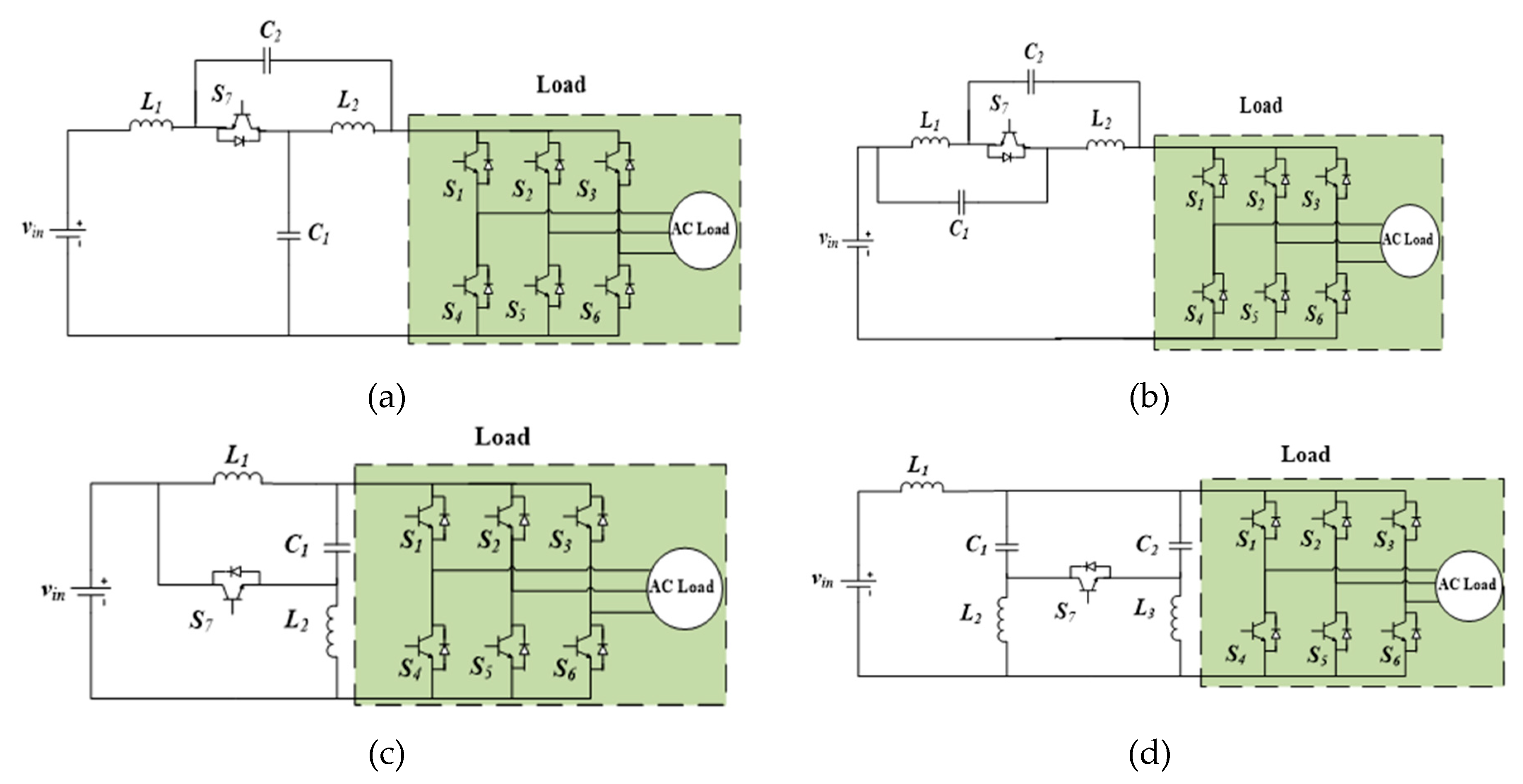
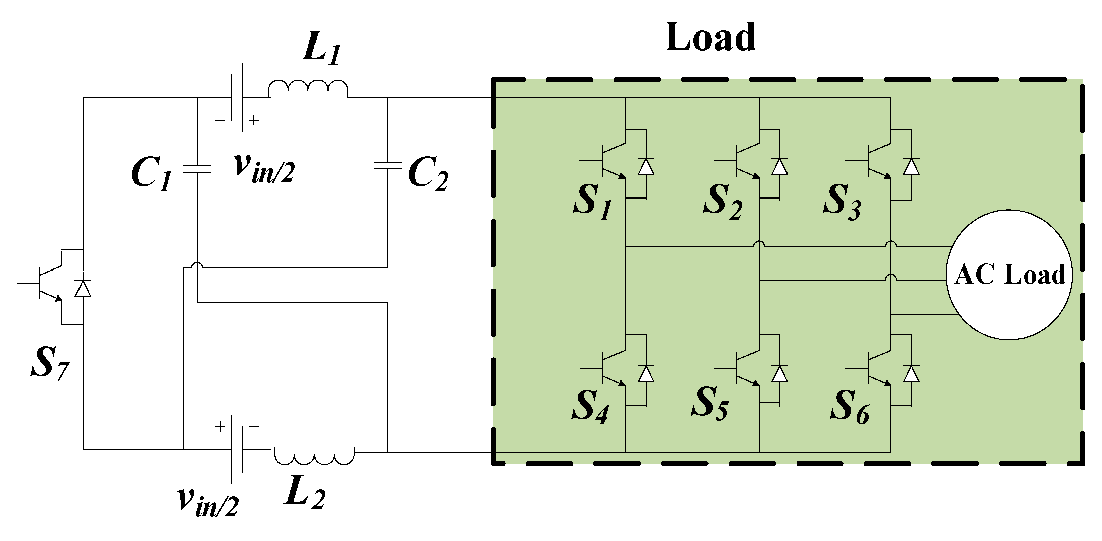
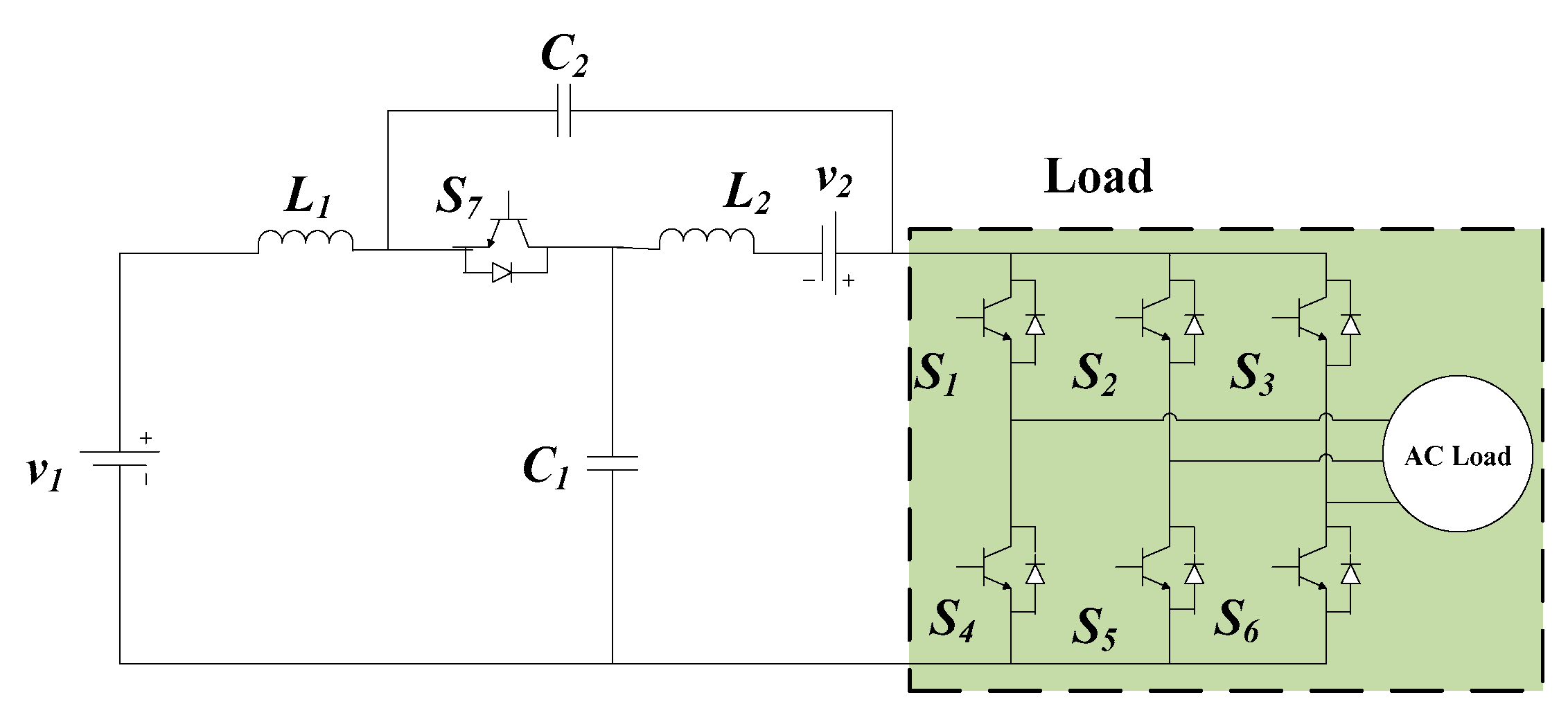
2.4. Embedded Quasi-Z-Source Inverter

The embedded quasi-Z-source inverter (EQZSI) maintains the features of typical quasi-Z-source inverter and is also able to produce smaller ripples of input voltage and continuous current [31,32]. It is able to draw a smooth current from a source, without adding other components. Figure 4 shows typical topology of an EQZSI. In this configuration, an additional DC source is embedded in the DC link of the classical QZSI. The concept of embedding the DC source permits to inherit the advantages of both QZSI and embedded topologies. The EQZSI topology enables it to operate well with one or two sources, without altering the voltage gain of QZSI topology. Its operating principle can be described in two states: the non-shoot-through state and the shoot-through one, like quasi-Z-source network. It can be suitable for battery storage systems and multisource power-conversion systems. Other similar embedded topologies with one or two DC sources also exist.

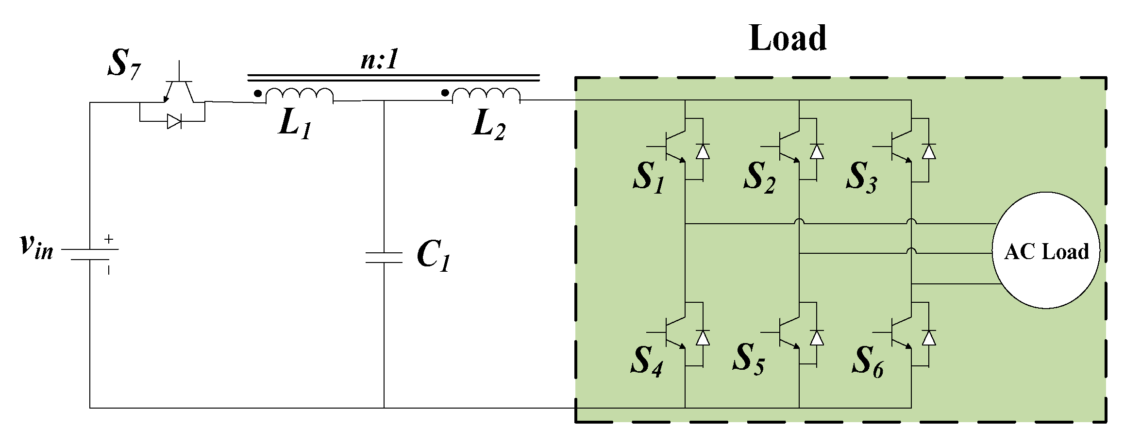
2.5. Trans-Z-Source Inverter

In theory, Z-source, quasi-Z-source, embedded Z-source and embedded quasi-Z-source all have unlimited voltage gain. However, in practice, a high voltage gain can impose high voltage stress on the switches. To overcome the aforementioned problem, Trans-Z-source (two voltage-fed and two current-fed) inverters were proposed to have higher voltage gains and to keep voltage stress low with Z-source network reduced to one transformer (or one coupled inductor) and one capacitor [33]. Trans-Z-source inverters not only maintain the main features of traditional Z-source inverters, but also exhibit some unique advantages by increasing voltage gains and reducing voltage stress. They are also able to operate at very low input voltage. The Trans-Z-source network has the operation and working principle similar to Z-source network and also eliminates the shoot-through barriers. However, transformers and coupled inductors which are used in its design increase volume and cost. Figure 5 shows the typical topology of Trans-Z-source inverter. This topology is very suitable for renewable energy generation [34].

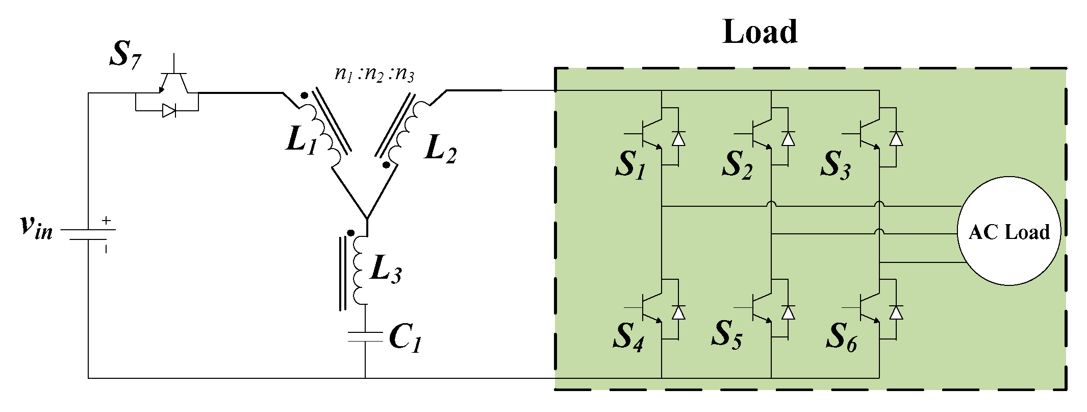
2.6. Y-Source Inverter

Y-source inverter is designed based on the Trans-Z-source inverter. The performance of the Y-source network inverter is close to that of the Trans-Z-source inverter. Y-source inverter topology was proposed in [16], using coupled inductors with three windings transformer (N1, N2 and N3). It has one more degree of freedom, such as the three windings and shoot-through duty cycle of switches. This degree of freedom permits users to choose the boost voltage comparatively to a classical impedance network design with boost converter. It reduces the total harmonic distortion (THD) of the inverter and realizes a higher voltage gain with small shoot-through duty cycle. The higher voltage boost and higher modulation index can be obtained at the same time with Y-source inverter. The Y-source impedance network also has the operation and working principle similar to the Z-source network. However, its leakage inductances of the coupled inductor due to discontinuous input current can produce the voltage overshoots [35]. With the diverse properties and the specific future of the Y-source network, many researchers and engineers continue to examine and modify the topology for the wide range of power-conversion applications. Figure 6 shows the Y-source inverter main topology.

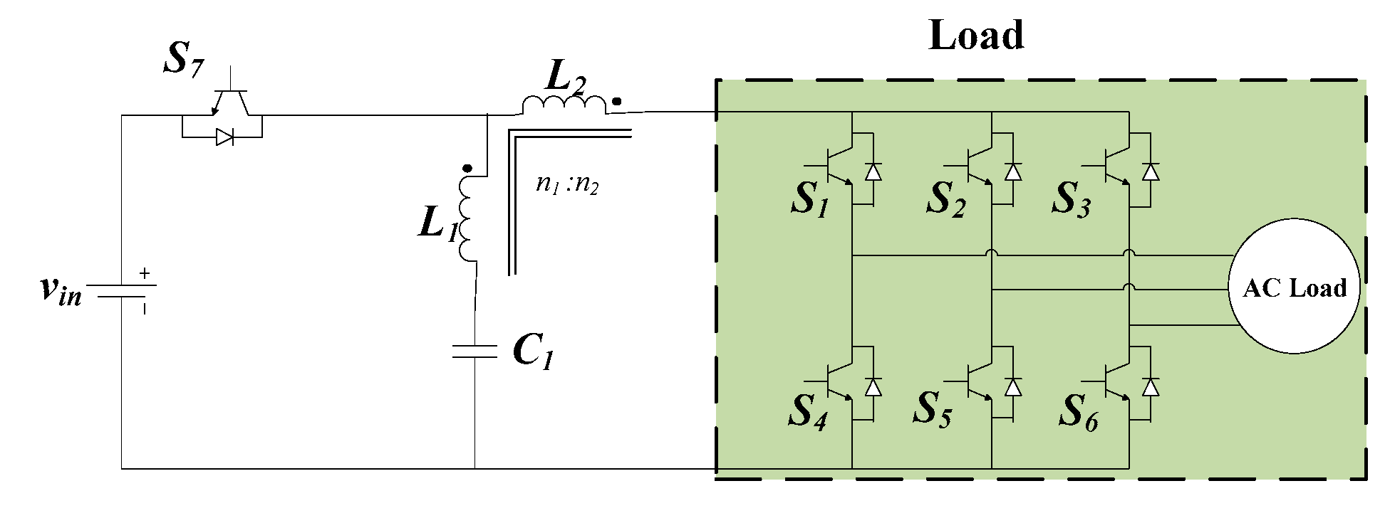
2.7. Γ-Z-Source Inverter

Γ-Z-source inverter is also derived from Trans-Z-source inverter [36]. Two Γ-shaped inductors are coupled in Trans-Z-source inverter to form the Γ-Z-source inverter, permitting it to increase the gain and modulation ratio, simultaneously [36]. The Γ-Z-source network gain is increased by decreasing the turn ratio. Figure 7 shows the Γ-Z-source inverter topology. Unlike other impedance source inverter whose gains increase with an increased turns ratio, such as Trans-Z-source and LCCT-Z-source, the Γ-Z-source inverter uses fewer components and a coupled transformer to achieve a high voltage gain by lowering the turn ratio. It represents the impedance source inverter which provides a better spectral performance. The drawback of this topology constitutes the presence of the leakage inductance that can affect the voltage and current stress on semiconductors. This topology is more convenient for renewable-energy generation.

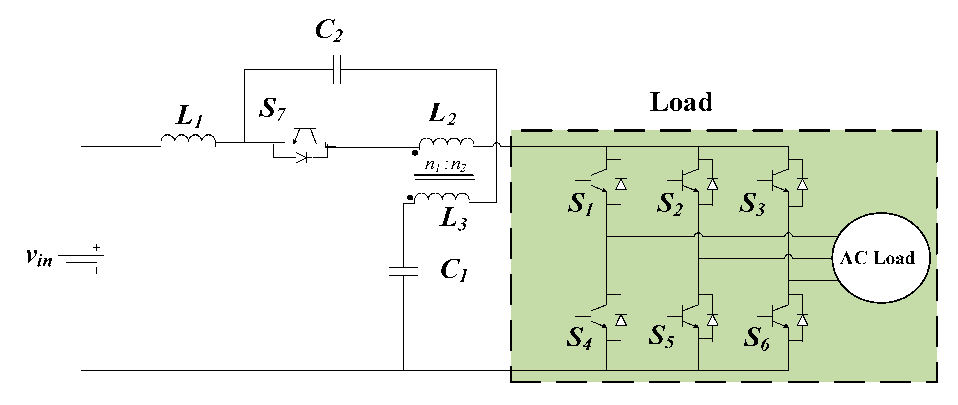
2.8. LCCT-Z-Source Inverter

As shown in Figure 8, the LCCT-Z-source inverter is extended from the Trans-Z-source. LCCT-Z-source network is an inductor–capacitor–capacitor–transformer Z-source network [17]. It can also be represented as an integration of high-frequency transformer with quasi-Z-source inverter. This topology produces continuous current even during light load and filters out high-frequency ripples from source current. It is able to achieve higher voltage gain and modulation index [18]. The unique feature of the LCCT-Z-source inverter is that its network helps to prevent the transformer core from saturation due to two capacitors, which block the source current [37], and during the boost operation, only one inductive element is used to store the energy. The LCCT-Z-source inverter is appropriate for renewable-energy generation and power-conversion applications.

2.9. Advantages and Disadvantages of the Main Impedance Source Network Topologies

The main impedance source network topologies exhibit several advantages and disadvantages. Table 1 shows the summary of the impedance source network topologies. Table 2 shows the main impedance source network topologies’ advantages and disadvantages. Their applications with the typical used power are also shown in Table 3. From the study of these various main impedance source inverters, we can see that the EQZSI is a promising architecture for multisource EV. It presents the advantage of having a continuous input current and retaining all the merits of both QZSI and embedded topologies.

3. Z-Source Inverters for EV Applications

3.1. Z-Source Inverters for Single-Source EV Applications

The efficient use of the available resources is one of the greatest technological concerns. With the ZSI, the improvements in DC–DC systems are going on in the field of EVs. The ZSI can regulate the voltages and currents of the energy sources and enables bidirectional flow of power in traction applications. In the propulsion mode, the voltage from the energy storage systems is provided by the ZSI, in the form of three-phase voltage, to drive the motor to produce the required torque and reach the desired speed of the vehicle. During the regenerative mode, the electric motor acts as a generator. The regenerated energy flows backward, to recharge the energy sources. The inverter operates as a rectifier, and the ZSI works as buck inverter, to recharge the energy sources. The schematic of the diagram of EV system components using an impedance source inverter is shown in Figure 9.
Since 2003, ZSI has been widely used in industrial applications, as well as in in a variety of other applications. ZSI has been applied to motor drives, to overcome the restrictions of voltage source inverter [13]. Bidirectional QZSI, which is the first modified topology of bidirectional ZSI, has also been compared with bidirectional conventional two-stage inverter for electric traction systems [49]. The results demonstrate that the transient and the steady-state performances are comparable for both topologies under the same operating conditions. However, the bidirectional QZSI shows lower inductor current ripples than bidirectional conventional two-stage inverter. The results also prove that the bidirectional QZSI shows higher efficiency than the conventional solution. Bidirectional ZSI, which can operate in boost mode, buck mode as a normal voltage source inverter, or a charger mode and applied to double-ended inverter drive system, is also proposed in [50]. To investigate the performance of locomotive drives, the ZSI has been used as a replacement for a voltage source inverter [51].
Because of many advantages of ZSI, it is suitably applied for fuel cell. A fuel-cell configuration using a Z-source network was represented in [52]. Three different inverters, namely a traditional voltage source inverter, conventional two-stage inverter and ZSI applied to a fuel-cell vehicle, have been compared [53]. The result shows that the ZSI has higher efficiency, less switching devices and more passive components requirement than the others type of inverters.

3.2. Z-Source Inverter for Multisource EV Applications

EV performance can be influenced by a lot of factors, including size, purpose of use, environment and driving style. For EV, these factors may lead to a deep and quick discharge rate of the battery. EV powered by a combination of multiple sources can contribute to keep the battery in good health [54]. That also helps the battery to slowly discharge, even when the EV uses a heavy load [55]. A hybrid energy storage system (HESS) combining two or more energy sources (batteries, ultracapacitor and fuel cell) has been shown to be a suitable solution, as it can meet the load-power requirement needed, depending on the characteristics of each source [56]. The conventional two-stage inverters are normally employed in these HESS.
In order to exploit the advantages of ZSIs, ultracapacitor-battery HESS for EVs based on asymmetric bidirectional Z-source topology has been studied [57]. The results demonstrate that the HESS with ZSI can be integrated into the traction system to obtain better performance and lower cost than that with conventional two-stage inverters. Furthermore, the ZSI can also be applied to hybrid electric vehicles using a fuel cell and battery as input sources, with slight modification in its topology [58]. Nonetheless, this configuration has some disadvantages with the obligation to use a high-voltage battery and the fact that the DC link voltage has twice the battery voltage during regenerative braking when the fuel cell stack is disconnected from the ZSI input terminals. This disconnection may damage the switches of the inverter.
There are many impedance source inverters which can be used for multisource EVs, such embedded Z-source inverter, embedded quasi-Z-source inverter and other topologies obtained with slight modification to include a battery or an additional DC source [58]. However, a multisource supply system for EVs with different power flows in traction and braking operations can be designed with bidirectional EQZSI. The EQZSI is a promising architecture for the multisource electric vehicle, as it presents the advantages of having a continuous input current and retaining all the merits of both QZSI and embedded topology [59].

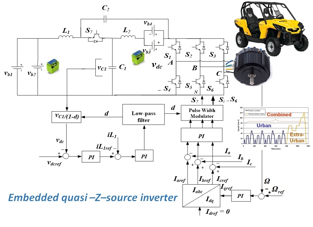
3.2.1. Bidirectional EQZSI for Multisource EV Applications

Electric Vehicle Specifications and Modeling

The reference electric vehicle is the e-TESC 4W platform, as presented in [59], with its main parameters. In our study, a permanent magnet synchronous machine (PMSM) was used as a traction electric motor, and its state space representation can be described as presented in [49].

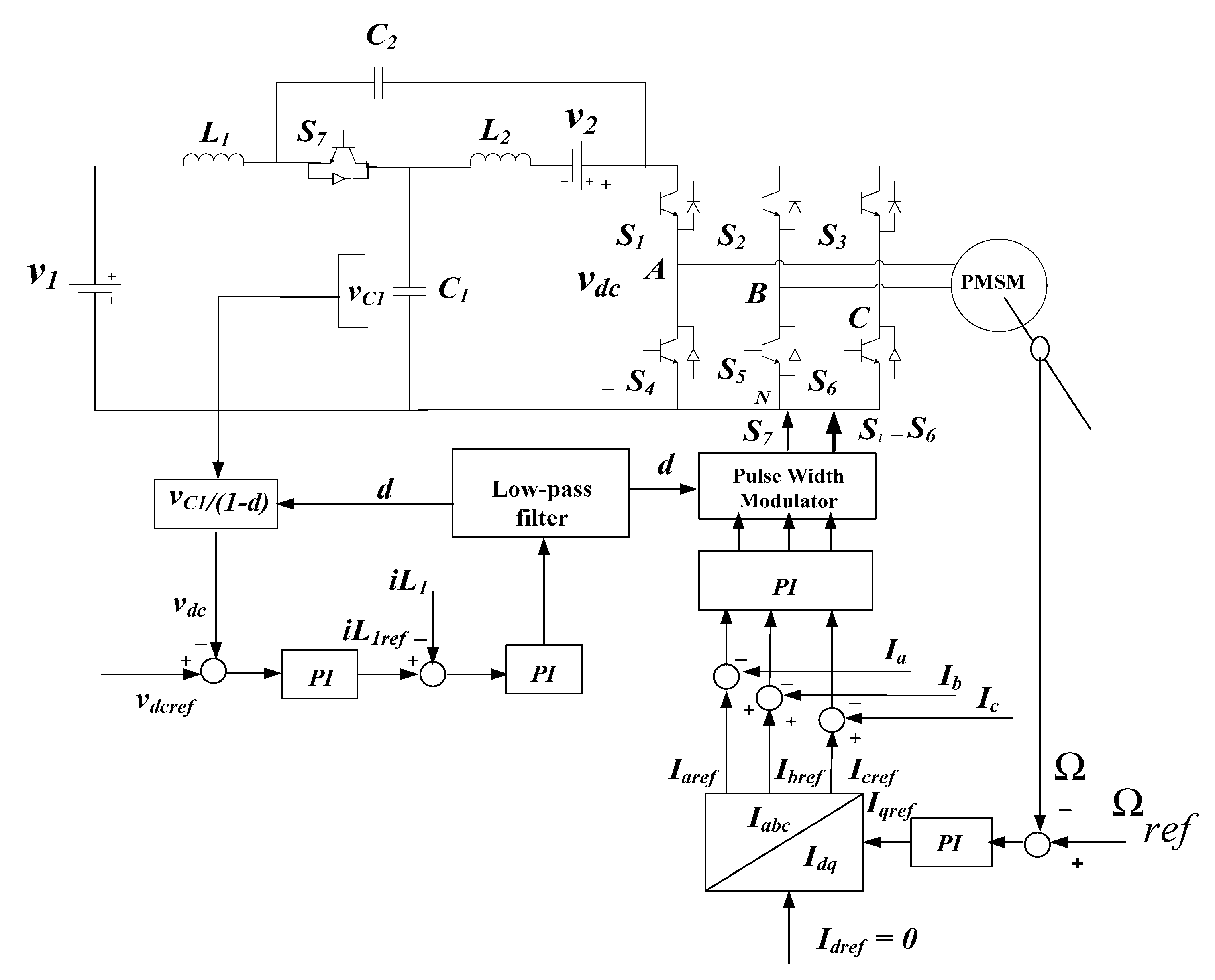
Modeling of Bidirectional Embedded Quasi-Z-Source Inverter

The bidirectional EQZSI, as presented in Section 2.4, can buck and boost the input voltage in a single stage with two control variables, namely the shoot-through duty ratio and the modulation index. Assuming T is one switching cycle, T0 is the interval of the shoot-through state and T1 is the interval of non-shoot-through state, their relationship is T0 + T1 = T, and the shoot-through duty ratio is D = T 0 T . The dynamic equations can be described as shown in [59]. During the steady state, the capacitor voltages and inductor currents can be deduced as follows:
{ v c 1 = 1 D 1 2 D v 1 + D 1 2 D v 2 v c 2 = D 1 2 D v 1 + 1 D 1 2 D v 2
i L 1 = i L 2 = 1 D 1 2 D i l o a d
The DC link peak voltage, v ^ d c , can be derived from the sum of two capacitor voltages, v c 1 and v c 2 , as follows:
v ^ d c = v c 1 + v c 2 = 1 1 2 D ( v 1 + v 2 ) = B ( v 1 + v 2 )
where B ≥ 1 is the boost factor resulting from the shoot through the period. With regards to the AC side of the EQZSI, the peak phase voltage can be written as follows:
v ^ o = m e v ^ d c 2 = m e 1 2 D · ( v 1 + v 2 ) 2 = G e ( v 1 + v 2 ) 2
where m e and G e are the inverter modulation index and total voltage gain of the EQZSI, respectively.

PI-Based Controllers Design

To achieve the speed control and disturbance rejection for the EV, cascade PI controllers were designed. The motor (PMSM) with PI control technique was adopted. The speed control scheme for EQZSI is shown in Figure 10.

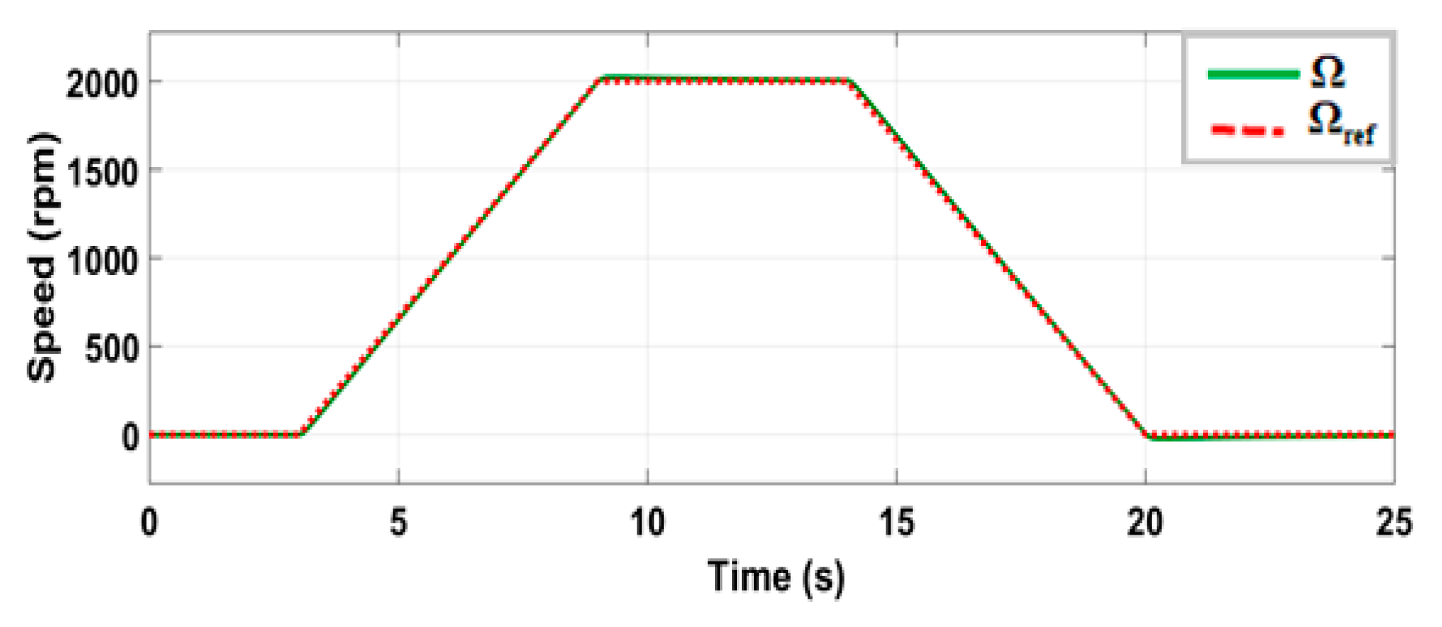
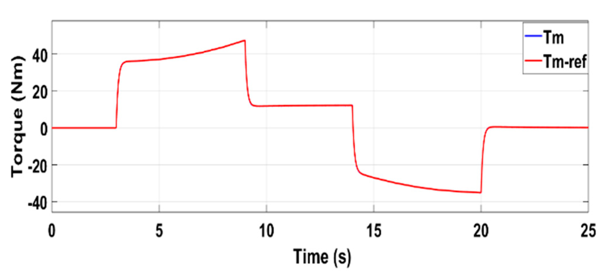
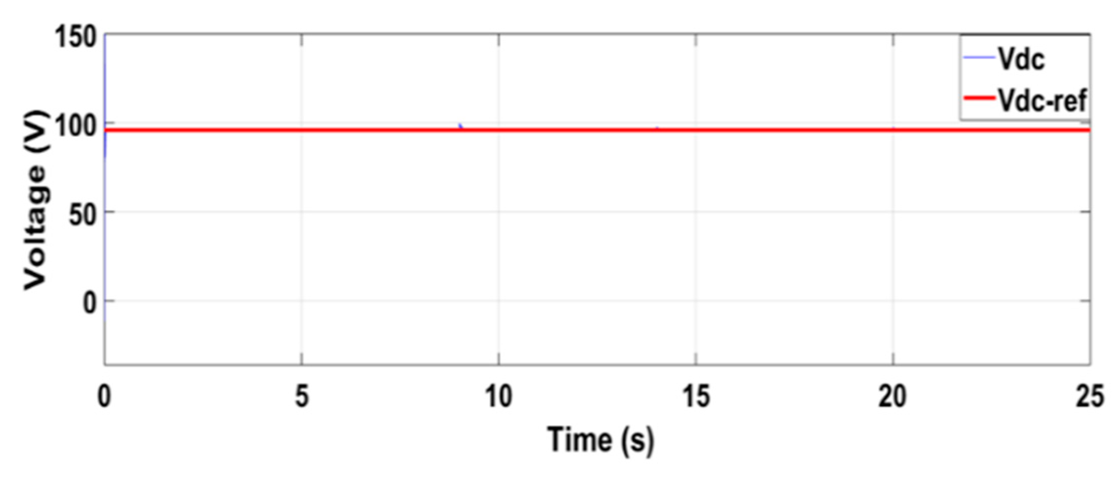
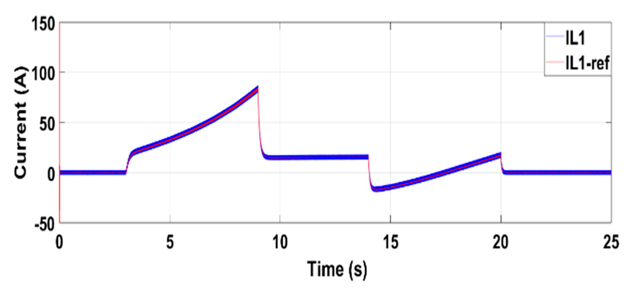
3.2.2. Simulation Results and Discussion

A simulation was carried out, to validate the model of EQZSI and show its performance for multisource EV. The bidirectional EQZSI performance depends on the selection of the parameters of embedded quasi-Z-source network elements. There are equations which can be used to determine the appropriate values of these parameters [60]. The critical values of the inductances and the capacitances are used to design the EQZSI parameters by the following equations:
L 1 = L 2 = D v c 1 f s Δ i L 1
C 1 = C 2 = D i L 1 f s Δ v c 1
where D is the shoot-through duty ratio, fs is the switching frequency, v c 1 is the average capacitor voltage, Δ i L 1 is the value of inductor current ripple at peak power to certain value, i L 1 is the average current of the inductor and Δ v c 1 represents the value of capacitor voltage ripple at peak power.
The simulation parameters are L 1 = L 2 = 230 μH; C 1 = C 2 = 2.2 mF. PWM carrier frequency for three-phase inverter is 10 kHz. The control scheme is shown in Section 3.2.1. Maximum constant boost control method as shown in [59] has been used to generate the gate signals of the EQZSI switches.
The electric vehicle motor used in the simulation is a PMSM with three phases, as defined in Section 3.2.1. The parameters of the motor are L d = L q = 1 mH; r s = 0.08 Ω; p = 2; ψ f = 0.1 Wb. The rated power is 15 kW. Figure 11 and Figure 12 show the speed and torque waveforms, respectively. Figure 13 and Figure 14 represent the v d c voltage and i L 1 current, as well as their references, respectively.
The results point out the ability of the inverter to respond quickly to the mechanical load and provide a DC bus constant voltage over all the power-demand profile. These results verify the bidirectional EQZSI as an alternative inverter for multisource EVs. The disparity of voltage levels and currents between the sources (fuel cell, batteries and ultracapacitors) and the loads of the EVs (traction motor and auxiliaries) requires the use of power converters. This kind of power-converter architecture provides a new interesting resource for on-board energy management in multisource EVs. The bidirectional EQZSI can enhance the performance of the EV by optimizing the electric power consumption and extending its driving range.

3.3. Future Trends

The concept of impedance source inverter has clearly opened up a new area of research in the field of power electronics. The study in Section 2 provides only a brief summary on topologies of impedance source inverters. It also shows the modifications that are possible to have with ZSI. Any topology possesses its own unique features and adapted applications. New impedance source inverters’ topologies may continue to appear to meet needs and improve performance in different applications. EVs, motor drives and renewable energy generation will be perspective applications for impedance source inverters, as impedance source inverters have a unique voltage buck–boost ability with minimum number of components and potential reduced cost. The control strategy is very important, as it ensures reliable and efficient operation of the impedance source inverter. The impedance source inverter system’s performance will be improved with novel control method. The use of a control method such as model predictive control (MPC) can contribute to enhance impedance source inverter system performance. The cost function of MPC is fundamental to the system performance, and different constraints can be added to improve the complete functioning of the system. The performance of impedance source inverters will also be enhanced with the new power electronics devices, such as the SiC and GaN, since they have high switching frequency, high temperature capacity and expected low cost. That can contribute to achieve smaller size for passive components of impedance source inverter, to reduce its cost and to increase its efficiency. The design of new impedance source inverters has attracted more and more attention from scientists and engineers. Impedance source inverter is still progressing in terms of topologies and applications.

4. Conclusions

A comprehensive start-of-the-art review of impedance source inverter main topologies was presented. The impedance source inverter for EV application and for other applications was outlined. Several topologies of ZSI were investigated. Many impedance source inverters were compared, in order to choose the best, most efficient and most convenient inverter topology for multisource EV. In the literature, a lot of approaches have been proposed, and their benefits and drawbacks were identified. The advantages and disadvantages of the impedance source inverter main topologies were presented. The impedance network becomes popular by the fact that it has specific features and attractive power-conversion ability. Impedance source inverters overcome many problems of traditional inverters. Since the apparition of Z-source network, numerous contributions in the literature modifying the basic topology to suit the needs of many applications have been proposed. It has been advanced to quasi-Z-source network, embedded Z-source network, embedded quasi-Z-source network, Trans-Z-source network and many other types of Z-source network topologies. The EQZSI is one of the promising architectures which can be used in EV multisource, with better performance and reliability. The utilization of this new topology will open the door to several development axes, with great impacts on EVs. Various researchers continue to work toward the modification of impedance source inverter main topologies, to increase their performance and applicability.

Author Contributions

Conceptualization, D.M. and J.P.T.; data curation, D.M. and J.P.T.; funding acquisition, J.P.T.; methodology, J.P.T. and M.C.T.; project administration, J.P.T.; validation, M.C.T.; writing—original draft, D.M.; writing—review and editing, J.P.T. and M.C.T. All authors have read and agreed to the published version of the manuscript.

Funding

This work was supported in part by Grant 950-230672 from Canada Research Chairs Program, in part by Grant RGPIN-2017-05924 from the Natural Sciences and Engineering Research Council of Canada, in part by FCT-Portuguese Foundation for Science and Technology project UIDB/00308/2020, and by the European Regional Development Fund, through the COMPETE 2020 Program within projects ESGRIDS (POCI-01-0145-FEDER-016434) and MAnAGER (POCI-01-0145-FEDER-028040).

Conflicts of Interest

The authors declare no conflict of interest.

References

  1. Codani, P.; le Portz, P.L.; Claverie, P.; Perez, Y.; Petit, M. Coupling local renewable energy production with electric vehicle charging: A survey of the French case. World Electr. Veh. J. 2015, 7, 489–499. [Google Scholar] [CrossRef] [Green Version]
  2. Colak, I.; Kabalci, E.; Bayindir, R. Review of multilevel voltage source inverter topologies and control schemes. Energy Convers. Manag. 2011, 52, 1114–1128. [Google Scholar] [CrossRef]
  3. Peng, F.Z. Z-Source Inverter. IEEE Trans. Ind. Appl. 2003, 39, 504–510. [Google Scholar] [CrossRef]
  4. Siwakoti, Y.P.; Peng, F.Z.; Blaabjerg, F. Impedance-source networks for electric power conversion part I: A topological review. IEEE Trans. Power Electron. 2015, 30, 699–716. [Google Scholar] [CrossRef]
  5. Peng, F.Z.; Joseph, A.; Wang, J.; Shen, M.; Chen, L.; Pan, Z.; Ortiz-Rivera, E.; Huang, Y. Z-Source Inverter for Motor Drives. IEEE Trans. Power Electron. 2005, 20, 857–863. [Google Scholar] [CrossRef]
  6. Cao, D.; Lei, Q.; Peng, F.Z. Development of high efficiency current-fed quasi-Z-source inverter for HEV motor drive. In Proceedings of the 2013 Twenty-Eighth Annual IEEE Applied Power Electronics Conference and Exposition (APEC), Long Beach, CA, USA, 17–21 March 2013; pp. 157–164. [Google Scholar]
  7. Vijay, V.; Shruthi, K.J.; Kini, P.G.; Viswanatha, C.; Bhatt, M.S. Modified Z-Source Inverter Based Three Phase Induction Motor Drive for Solar PV Applications (EPSCICON). In Proceedings of the 2014 International Conference on Power Signals Control and Computations, Thrissur, India, 6–11 January 2014. [Google Scholar]
  8. Cortés, P.; Ortiz, G.; Yuz, J.I.; Rodríguez, J.; Vazquez, S.; Franquelo, L.G. Model Predictive Control of an Inverter with Output LC Filter for UPS Applications. IEEE Trans. Ind. Electron. 2009, 56, 1875–1883. [Google Scholar] [CrossRef]
  9. Yu, Y.; Zhang, Q.; Liang, B.; Liu, X.; Cui, S. Analysis of a Single-Phase Z-Source Inverter for Battery Discharging in Vehicle to Grid Applications. Energies 2011, 4, 2224–2235. [Google Scholar] [CrossRef] [Green Version]
  10. Gajanayake, C.J.; Vilathgamuwa, D.M.; Loh, P.C.; Teodorescu, R.; Blaabjerg, F. Z-Source-Inverter-Based Flexible Distributed Generation System Solution for Grid Power Quality Improvement. IEEE Trans. Energy Convers. 2009, 24, 695–704. [Google Scholar] [CrossRef]
  11. Shahinpour, A.; Moghani, J.S.; Gharehpetian, G.B.; Abdi, B. High Gain High-Voltage Z-Source Converter for Offshore Wind Energy Systems. In Proceedings of the 5th Annual International Power Electronics, Drive Systems and Technologies Conference (PEDSTC 2014), Tehran, Iran, 5–6 February 2014; pp. 488–493. [Google Scholar]
  12. Bharanikumar, R.; Senthilkumar, R.; Kumar, A.N. Impedance source inverter for wind turbine driven permanent magnet generator. In Proceedings of the 2008 Joint International Conference on Power System Technology and IEEE Power India Conference, New Delhi, India, 12–15 October 2018; pp. 1–7. [Google Scholar]
  13. Peng, F.Z.; Yuan, X.; Fang, X.; Qian, Z. Z-source inverter for adjustable speed drives. IEEE Power Electron. Lett. 2003, 1, 33–35. [Google Scholar] [CrossRef]
  14. Dehghan, S.M.; Mohamadian, M.; Yazdian, A. Hybrid electric vehicle based on bidirectional Z-source nine-switch inverter. IEEE Trans. Veh. Technol. 2010, 59, 2641–2653. [Google Scholar] [CrossRef]
  15. Hanif, M.; Basu, M.; Gaughan, K. Understanding the Operation of a Z-source inverter for photovoltaic application with a design example. IET Power Electron. 2011, 4, 278–287. [Google Scholar] [CrossRef]
  16. Siwakoti, Y.P.; Loh, P.C.; Blaabjerg, F.; Town, G.E. Y-Source Impedance Network. IEEE Trans. Power Electron. 2014, 29, 3250–3254. [Google Scholar] [CrossRef]
  17. Loh, P.C.; Li, D.; Blaabjerg, F. Γ-Z-Source Inverters. IEEE Trans. Power Electron. 2013, 28, 4880–4884. [Google Scholar] [CrossRef]
  18. Adamowicz, M. LCCT-Z-Source Inverters. In Proceedings of the 2011 10th International Conference on Environment and Electrical Engineering, Rome, Italy, 8–11 May 2011; pp. 1–6. [Google Scholar]
  19. Liu, Y.; Ge, B.; Ferreira, F.J.T.E.; de Almeida, A.T.; Rub, A.A. Modeling and SVPWM control of quasi-Z-source inverter. In Proceedings of the 11th IEEE International Conference on Electrical Power Quality and Utilisation, Lisbon, Portugal, 17–19 October 2011; pp. 1–7. [Google Scholar]
  20. Gajanayake, C.J.; Vilathgamuwa, D.M.; Loh, P.C. Development of a Comprehensive Model and a Multiloop Controller for Z-Source Inverter DG Systems. IEEE Trans. Ind. Electron. 2007, 54, 2352–2359. [Google Scholar] [CrossRef]
  21. Gupta, A.K.; Ahmad, A.; Samuel, P. HDL Co-Simulation of Single Phase Z-Source Inverter. In Proceedings of the IEEE Student Conference on Engineering and System SCES, Allahabad, India, 12–14 April 2013. [Google Scholar]
  22. Peng, F.Z.; Shen, M.; Qian, Z. Maximum boost control of the Z-source inverter. IEEE Trans. Power Electron. 2005, 20, 833–838. [Google Scholar] [CrossRef]
  23. Shen, M.; Peng, F.Z. Operation Modes and Characteristics of the Z-Source Inverter with Small Inductance or Low Power Factor. IEEE Trans. Ind. Electron. 2008, 55, 89–96. [Google Scholar] [CrossRef]
  24. Rostami, H.; Khaburi, D.A. Voltage gain comparison of different control methods of the Z-source inverter. In Proceedings of the IEEE International Conference on Electrical and Electronics Engineering (ELECO 2009), Bursa, Turkey, 5–8 November 2009; pp. I-268–I-272. [Google Scholar]
  25. Zhu, M.; Yu, K.; Luo, F.L. Switched Inductor Z-Source Inverter. IEEE Trans. Power Electron. 2010, 25, 2150–2158. [Google Scholar]
  26. Nguyen, M.K.; Lim, Y.C.; Cho, G.B. Switched-inductor quasi-Z-source inverter. IEEE Trans. Power Electron. 2011, 26, 3183–3191. [Google Scholar] [CrossRef]
  27. Singh, C.S.; Tripathi, R.K. Maximum Constant Boost Control of Switch Inductor Quasi-Z-Source Inverter. In Proceedings of the IEEE Student conference on Engineering and System (SCES 2013), Allahabad, India, 12–14 April 2013. [Google Scholar]
  28. Anderson, J.; Peng, F.Z. Four Quasi-Z-Source Inverters. In Proceedings of the 2008 IEEE Power Electronics Specialists Conference, Rhodes, Greece, 15–19 June 2008; Volume 58, pp. 2743–2749. [Google Scholar]
  29. Guo, F.; Fu, L.; Lin, C.H.; Li, C.; Choi, W.; Wang, J. Development of an 85-kW Bidirectional Quasi-Z-Source Inverter with DC-Link Feed-Forward Compensation for Electric Vehicle Applications. IEEE Trans. Power Electron. 2003, 28, 5477–5488. [Google Scholar] [CrossRef]
  30. Loh, P.C.; Gao, F.; Blaabjerg, F. Embedded EZ-Source Inverters. IEEE Trans. Power Electron. 2010, 46, 256–267. [Google Scholar]
  31. Ho, A.; Hyun, J.; Chun, T.; Lee, H. Embedded quasi-Z-source inverters based on active switched-capacitor structure. In Proceedings of the IECON 2016—42nd Annual Conference of the IEEE Industrial Electronics Society, Florence, Italy, 23–26 October 2016; pp. 3384–3389. [Google Scholar]
  32. Nisha, K.C.R. PV powered generalized multicell switched-inductor embedded quasi-Z-source inverter using MSP-430 controller. In Proceedings of the 2016 International Conference on Circuit, Power and Computing Technologies (ICCPCT), Nagercoil, India, 18–19 March 2016; pp. 1–6. [Google Scholar]
  33. Qian, W.; Peng, F.Z.; Cha, H. Trans-Z-source inverters. IEEE Trans. Power Electron. 2011, 26, 3453–3463. [Google Scholar] [CrossRef]
  34. Bajestan, M.M.; Shahparasti, M.; Khaburi, D.A. Application of trans Z-source inverter in photovoltaic systems. In Proceedings of the 21st Iranian Conference on Electrical Engineering (ICEE), Mashhad, Iran, 14–16 May 2013; pp. 1–6. [Google Scholar]
  35. Siwakoti, Y.P.; Loh, P.C.; Blaabjerg, F.; Town, G.E. Effects of Leakage Inductances on Magnetically Coupled Y-Source Network. IEEE Trans. Power Electron. 2014, 29, 5662–5666. [Google Scholar] [CrossRef]
  36. Adamowicz, M.; Strzelecki, R.; Peng, F.Z.; Guzinski, J.; Rub, H.A. High step-up continuous input current LCCT-Z-source inverters for fuel cells. In Proceedings of the IEEE Energy Conversion Congress and Exposition, Phoenix, AZ, USA, 17–22 September 2011; pp. 2276–2282. [Google Scholar]
  37. Adamowicz, M.; Strzelecki, R.; Peng, F.Z.; Guzinski, J.; Rub, H.A. New type LCCT-Z-source inverters. In Proceedings of the European Conference on Power Electronics and Applications (EPE), Birmingham, UK, 30 August–1 September 2011; pp. 1–10. [Google Scholar]
  38. Ellabban, O.; Mierlo, J.V.; Lataire, P.; den Bossche, P.V. Z-Source Inverter for Vehicular Applications. In Proceedings of the IEEE Vehicle Power and Propulsion Conference, Chicago, IL, USA, 6–9 September 2011. [Google Scholar]
  39. Pattanaphol, A.; Khomfoi, S.; Paisuwanna, P. Z-Source Grid-Connected Inverter for Solving the photovoltaic cell Shading problem. In Proceedings of the ECTI-CON2010: The 2010 ECTI International Conference on Electrical Engineering/Electronics, Computer, Telecommunications and Information Technology, Chiang Mai, Thailand, 19–21 May 2010; pp. 823–827. [Google Scholar]
  40. Hernández, N.M.; Cardoso, G.J.; Azcue-Puma, J.L.; Torrico, J.A.A.; Alfeu, J.; Sguarezi, F. Z-Source Inverter Applied to Wind Power System with Battery Energy Storage System. In Proceedings of the IEEE International Conference on Industry Applications (INDUSCON), Curitiba, Brazil, 20–23 November 2016; pp. 1–6. [Google Scholar]
  41. Beer, K.; Piepenbreie, B. Properties and Advantages of the Quasi-Z-Source Inverter for DC-AC Conversion for Electric Vehicle Applications. In Proceedings of the IEEE Conference on Emobility-Electrical Power Train, Leipzig, Germany, 8–9 November 2010; pp. 1–6. [Google Scholar]
  42. Zhang, Y.; Liu, Q.; Li, J.; Sumner, M.A. Common Ground Switched-Quasi-Z -Source Bidirectional DC–DC Converter with Wide-Voltage-Gain Range for EVs with Hybrid Energy Sources. IEEE Trans. Ind. Electron. 2018, 65, 5188–5200. [Google Scholar] [CrossRef]
  43. Park, J.H.; Kim, H.G.; Nho, E.C.; Chun, T.-W.; Choi, J. Grid-connected PV System Using a Quasi-Z-source Inverter. In Proceedings of the 2009 Twenty-Fourth Annual IEEE Applied Power Electronics Conference and Exposition, Washington, DC, USA, 15–19 February 2009; pp. 925–929. [Google Scholar]
  44. Khani, S.; Mohammadian, L.; Hosseini, S.H.; Ghasemzadeh, S. Design and Control of Fully Parallel Embedded Z-Source Inverters Based Flexible Photovoltaic Systems for Grid Power Quality Improvement under Distorted Condition. In Proceedings of the IEEE 21st Iranian Conference on Electrical Engineering (ICEE), Mashhad, Iran, 14–16 May 2013; pp. 1–7. [Google Scholar]
  45. Jiang, S.; Peng, F.Z. Modular Single-Phase Trans-Z-Source Inverter for Multi-Input Renewable Energy System. In Proceedings of the IEEE Applied Power Electronics Conference and Exposition (APEC), Orlando, FL, USA, 5–9 February 2012; pp. 2107–2114. [Google Scholar]
  46. Shehata, E.G. Predictive control of a new configuration of bidirectional quasi Y-source inverter fed IPMSM for electric vehicle applications. In Proceedings of the IEEE Nineteenth International Middle East Power Systems Conference (MEPCON), Cairo, Egypt, 19–21 December 2017; pp. 287–292. [Google Scholar]
  47. Forouzesh, M.; Baghramian, A.; Salavati, N. Improved Y-Source Inverter for Distributed Power Generation. In Proceedings of the IEEE 23rd Iranian Conference on Electrical Engineering (ICEE), Tehran, Iran, 10–14 May 2015; pp. 1677–1681. [Google Scholar]
  48. Khoshkhati, F.; Toofan, S.; Asaei, B. Modeling and control of asymmetric Γ-source inverters for photovoltaic applications. Int. J. Tech. Phys. Probl. Eng. (IJTPE) 2014, 6, 138–144. [Google Scholar]
  49. Daouda, M.; Trovao, J.P.; Rubio, R.G.; Ta, M.C. Comparison of Bidirectional Quasi-Z-Source Inverter and Bidirectional Conventional Two-Stage Inverter for Electric Traction System. In Proceedings of the IEEE Vehicle Power and Propulsion Conference (VPPC), Chicago, IL, USA, 27–30 August 2018; pp. 1–6. [Google Scholar]
  50. Welchko, B.A.; Nagashima, J.M.; Smith, G.S.; Chakrabarti, S.; Perisic, M.; John, G. Double Ended Inverter System with an Impedance Source Inverter Subsystem. U.S. Patent No. US7956569, 7 June 2011. [Google Scholar]
  51. Vasanthi, V.; Ashok, S. Performance evaluation of Z source inverter fed locomotive drives with different control topologies. In Proceedings of the IEEE International Conference on Power Electronics, Drives and Energy Systems, Bengaluru, India, 16–19 December 2012; pp. 1–4. [Google Scholar]
  52. Jung, J.; Keyhani, A. Control of a Fuel Cell Based Z-Source Converter. IEEE Trans. Energy Convers. 2007, 22, 467–476. [Google Scholar] [CrossRef]
  53. Shen, M.; Joseph, A.; Wang, J.; Peng, F.Z.; Adams, D.J. Comparison of traditional inverters and Z-source inverter for fuel cell vehicles. IEEE Trans. Power Electron. 2007, 22, 1453–1463. [Google Scholar] [CrossRef]
  54. Trovão, J.P.; Santos, V.D.N.; Pereirinha, P.G.; Jorge, H.M.; Antunes, C.H. Comparative Study of Different Energy Management Strategies for Dual-Source Electric Vehicles. World Electr. Veh. J. 2013, 6, 523–531. [Google Scholar] [CrossRef] [Green Version]
  55. Iversen, E.B.; Morales, J.M.; Madsen, H. Optimal charging of an electric vehicle using a Markov decision process. Appl. Energy 2014, 123, 1–12. [Google Scholar] [CrossRef] [Green Version]
  56. Zhang, F.; Hu, X.; Langari, R.; Cao, D. Energy management strategies of connected HEVs and PHEVs: Recent progress and outlook. Prog. Energy Combust. Sci. 2019, 73, 235–256. [Google Scholar] [CrossRef]
  57. Hu, S.; Liang, Z.; He, X. Ultracapacitor-Battery Hybrid Energy Storage System Based on the Asymmetric Bidirectional Z-Source Topology for EV. IEEE Trans. Power Electron. 2016, 31, 7489–7498. [Google Scholar] [CrossRef]
  58. Ellabban, O.; Van Mierlo, J.; Lataire, P. Control of a High-Performance Z-Source Inverter for Fuel Cell/Supercapacitor Hybrid Electric Vehicles. World Electr. Veh. J. 2010, 4, 444–451. [Google Scholar] [CrossRef]
  59. Mande, D.; Trovão, J.P.; Rubio, R.G.; Ta, M.C. Comparison of Different Power Train Topologies for an Off-Road Electric Vehicle. In Proceedings of the IEEE Vehicle Power and Propulsion Conference (VPPC), Hanoi, Vietnam, 14–17 October 2019; pp. 1–6. [Google Scholar]
  60. Godavarthi, N.K.; Lakshmi, P.S.R.; Devi, V.T.S. Comparative analysis of PWM methods of Quasi Z source Inverter. In Proceedings of the IEEE conferences International Conference on Renewable Energy and Sustainable Energy (ICRESE), Coimbatore, India, 5–6 December 2013; pp. 86–90. [Google Scholar]
Figure 1. Bidirectional Z-source inverter main topology.
Wevj 11 00037 g001
Figure 2. Bidirectional quasi-Z-source inverter topologies: voltage-fed one with continuous current (a); voltage-fed one with discontinuous current (b); current-fed one with continuous current (c); current-fed one with discontinuous current (d).
Wevj 11 00037 g002
Figure 3. Bidirectional embedded Z-source inverter topology.
Wevj 11 00037 g003
Figure 4. Bidirectional embedded quasi-Z-source inverter topology.
Wevj 11 00037 g004
Figure 5. Bidirectional Trans-Z-source inverter topology.
Wevj 11 00037 g005
Figure 6. Bidirectional Y-source inverter topology.
Wevj 11 00037 g006
Figure 7. Bidirectional Γ-source inverter topology.
Wevj 11 00037 g007
Figure 8. Bidirectional LCCT-Z-source inverter topology.
Wevj 11 00037 g008
Figure 9. Schematic diagram of electric vehicle (EV) system components.
Wevj 11 00037 g009
Figure 10. Typical speed-control scheme based on PI controllers for EQZSI.
Wevj 11 00037 g010
Figure 11. Motor speed and reference with EQZSI.
Wevj 11 00037 g011
Figure 12. Motor torque and reference with EQZSI.
Wevj 11 00037 g012
Figure 13. The v d c voltage and reference with EQZSI.
Wevj 11 00037 g013
Figure 14. The i L 1 current and reference with EQZSI.
Wevj 11 00037 g014
Table 1. Summary of the impedance source network topologies.
Impedance NetworkFigure #Boost Factor BSwitching DevicesNumber of CapacitorsNumber of InductorsVoltage Stress on the Switching Device
Z-Source# 1 1 1 2 D
where, 0 D 0.5
122 1 1 2 D v i n
Quasi-Z-Source# 2a 1 1 2 D
where, 0 D 0.5
122 1 1 2 D v i n
Embedded Z-Source# 3 1 1 2 D
where, 0 D 0.5
122 1 1 2 D v i n
Embedded Quasi-Z-Source# 4 1 1 2 D
where, 0 D 0.5
122 1 1 2 D ( v 1 + v 2 )
Trans-Z-Source# 5 1 1 ( n + 1 ) D
where, 0 D
( n + 1 ) 1
n    
11Integrated two windings n 1 ( n + 1 ) D v i n
Y-Source# 6 1 1 K D
where, K 2 and
0 D 1 K
11Integrated three windings K 1 1 K D v i n
Γ-Z-source# 7 1 1 [ 1 + ( n 1 ) 1 ] D
where, 0 D
[ 1 + ( n 1 ) 1 ] 1
1 < n < 2
n     *
12One inductor and one 2 windings coupled inductor 1 ( n 1 ) [ 1 ( 1 + ( n 1 ) 1 ) D ] v i n
LCCT-Z-source# 8 1 1 ( n + 1 ) D
where, 0 D
( n + 1 ) 1
n    
122 n 1 ( n + 1 ) D v i n
Table 2. Summary of the impedance source network topologies’ advantages and disadvantages.
Impedance NetworkAdvantagesDisadvantages
Z-Source- Overcomes the disadvantages of voltage source and current source inverters.
- Offers novel power conversion concept.
- Both switches from the same leg trigger at the same time do not cause any failure.
- Inductor of current fed ZSI sustains high current.
- Benefits to motor drives and renewable-energy-generation applications.
- Discontinuous input current.
- Not suitable for very low input DC voltages [25].
- Cannot suppress the inrush current.
- Different grounds for source and inverter circuits [26].
- High-voltage capacitors, which are required, increase the cost and volume of the system.
- The shoot-through duty ratio must always be less than 0.5.
Quasi-Z-Source- Continuous input current.
- Reduces passive component ratings.
- Provides lower current stress on inductors compared to ZSI.
- Shares common ground with input DC supply [26].
- Benefits to motor drives and renewable-energy-generation applications.
- The shoot-through duty ratio must always be less than 0.5.
- Not suitable for very low input DC voltage.
Embedded Z-Source- Draws smooth current from source, without additional component.
- Produce smaller ripples of input voltage and current.
- Suitable for battery storage systems and PV-power generation.
- Different stress distribution among components, provided by its asymmetrical structure.
- Supplied current is no longer maintained.
- The shoot-through-duty ratio must always be less than 0.5.
Embedded Quasi-Z-Source- Continuous input current.
- Draws smooth current from source, without additional component.
- Appropriate for battery storage systems and multisource power-conversion systems.
-The shoot-through duty ratio must always be less than 0.5.
- Not suitable for very low input DC voltages.
Trans-Z-Source- Increases voltage gain more than the case of Z-source and quasi-Z-source network.
- Reduces component stress.
- Able to operate on very low input voltage.
- Suitable for renewable-energy generation.
- High gain is obtained with high winding-turns ratio.
- Discontinuous input current.
- Transformers and coupled inductors increase volume and cost.
Y-Source- Very high gain can be obtained with small shoot-through-duty cycle.
- Higher voltage boost and higher modulation index can be obtained at the same time.
- Reduced THD of the inverter.
- Suitable for power-conversion applications.
- Discontinuous input current.
- Electromagnetic interference noise affects its reliability.
Γ-Z-source- High gain can be achieved by lowering turn ratio.
- Better spectral performance.
- Continuous input current.
- Convenient for renewable energy generation.
- Leakage inductance affects the voltage and current stress over semiconductors.
LCCT-Z-source- Have continuous current even during light load.
- Filter out high-frequency ripples from source current.
- Appropriate for renewable-energy generation and power-conversion applications.
- Have high winding-turns ratio.
- Electromagnetic interference noise affects its reliability.
Table 3. Summary of the impedance source inverter applications with typical used power.
Impedance Network TopologySwitching FrequencyTypical Used PowerApplications
Z-Source10 kHz15 kW (maximum output power)Electric vehicles [38]
125 kW (maximum output power)Photovoltaic and Grid systems [39]
12 kHz4.5 kW (rated power)Wind Turbines [40]
Quasi-Z-Source100 kHz10.6 kW (maximum output power)Electric vehicles [41]
20 kHz300 W (rated power)Hybrid electric vehicles [42]
10 kHz2.6 kW (rated power)Photovoltaic and Grid systems [43]
Embedded Z-Source7 kHz6 kW (maximum output power)Photovoltaic and Grid systems [44]
Embedded Quasi-Z-Source10 kHz375 W (maximum output power)Photovoltaic [32]
Trans-Z-Source20 kHz6 kW (rated power)Photovoltaic, fuel cell and Grid system [45]
Y-Source20 kHz2 kW (maximum output power)Electric vehicle [46]
10 kHz18.25 kW (maximum output power)Photovoltaic [47]
Γ-Z-source10 kHz3 kW (maximum output power)Photovoltaic and Grid systems [48]
LCCT-Z-source20 kHz4.5 kW (rated power)Permanent magnet synchronous generators [18]

