1. Introduction
For unmanned vehicles, especially off-road unmanned vehicles, obstacle detection and avoidance are very important [
1,
2]. Semi-trailers are often used for off-road transport, and the goods being transported include ore and wood. So, obstacle avoidance of semi-trailers is a key technology of autonomous off-road transportation.
At present, there are two kinds of common obstacle avoidance methods for vehicles. One is non-global path planning, and the other is obstacle avoidance control through model predictive control (MPC). There are many obstacle avoidance methods based on path planning. Yuan proposed a multi-layer obstacle avoidance path planning method for tractor-trailer mobile robots [
3]. Sgorbissa and Zaccaria proposed an improved path planning algorithm based on Artificial Potential Fields (APFs) [
4]. Fahimi et al. proposed a method that allows multiple robots to avoid each other [
5]. There is no doubt that these works are significant. However, researchers who study path planning often treat the vehicle as a point and do not focus on the constraints of the vehicle.
MPC is a control method that can explicitly take system constraints into consideration [
6]. Thus, MPC is increasingly being applied to the control of vehicles. Yoon et al. proposed an obstacle avoidance controller based on MPC [
7]. Frasch et al. improved the real-time performance of the MPC-based obstacle avoidance controller [
8]. Gong et al. designed an MPC-based obstacle avoidance method based on the penalty function [
9]. Nayl et al. proposed an MPC-based obstacle avoidance method for an articulated vehicle [
10]. Wang et al. proposed an obstacle avoidance controller for three-dimensional space [
11]. Liu et al. improved the robustness of the MPC-based obstacle avoidance controller and proposed a controller that simultaneously adjusts the velocity and heading [
12,
13]. Hua et al. proposed an MPC-based obstacle avoidance method based on the restricted areas penalty function [
14]. We propose a nonlinear MPC-based obstacle avoidance controller for agricultural trailers [
15]. These studies are of great significance for the application of MPC in the obstacle avoidance control of vehicles. However, in these papers, the vehicle was treated as a circumcircle of the vehicle or just a point.
It is safe to treat a small-sized robot as a point, but treating a large-sized vehicle as a point may cause a collision between the vehicle and the obstacle. Considering the vehicle as a circumcircle of the vehicle can avoid collisions completely. This model is safe for the obstacle avoidance control of the vehicle. However, for vehicles with a large length, the radius of the circumcircle is too large compared to the width of the body. For example, if the semi-trailer is treated as a circumcircle and the length of the semi-trailer is 16 m, the controller will have to control the vehicle to avoid obstacles within 8 m from the side of the body. For normal driving, it is not necessary for the distance between the vehicle and the obstacle to be so large. Moreover, treating the vehicle as a circumcircle will reduce the passable area of the vehicle.
Therefore, we believe that it is necessary to propose a new MPC-based controller for the obstacle avoidance control of semi-trailers. In this paper, the main contribution is to propose an obstacle avoidance model, and, based on this model, an obstacle avoidance controller for semi-trailers is designed. Compared to controllers based on the circumcircle model, the proposed controller can reduce the error between the vehicle and the reference path while ensuring no collisions occur.
The rest of this paper is arranged as follows:
Section 2 introduces the obstacle avoidance model. In
Section 3, the MPC controller is designed. Moreover, simulation results are given in
Section 4. A brief conclusion of this paper is presented in
Section 5.
2. Obstacle Avoidance Model
Both dynamic models [
16] and kinematics models [
17,
18,
19,
20,
21] can be used as the basis for the obstacle avoidance model. The dynamic model can accurately provide the position and posture of the vehicle, but this model is very complicated. Compared to the dynamic model, the kinematics model is simple, and when the driving velocity is not too high, the position and posture of the vehicle also can be accurately provided. Since the purpose of this paper is to propose an obstacle avoidance controller for off-road semi-trailers, and the off-road semi-trailer usually travels at low velocities, we use the kinematics model as the basis for the obstacle avoidance model. If a high velocity needs to be considered, a new obstacle avoidance model can be obtained by replacing the kinematics model with a dynamic model.
2.1. Kinematics Model
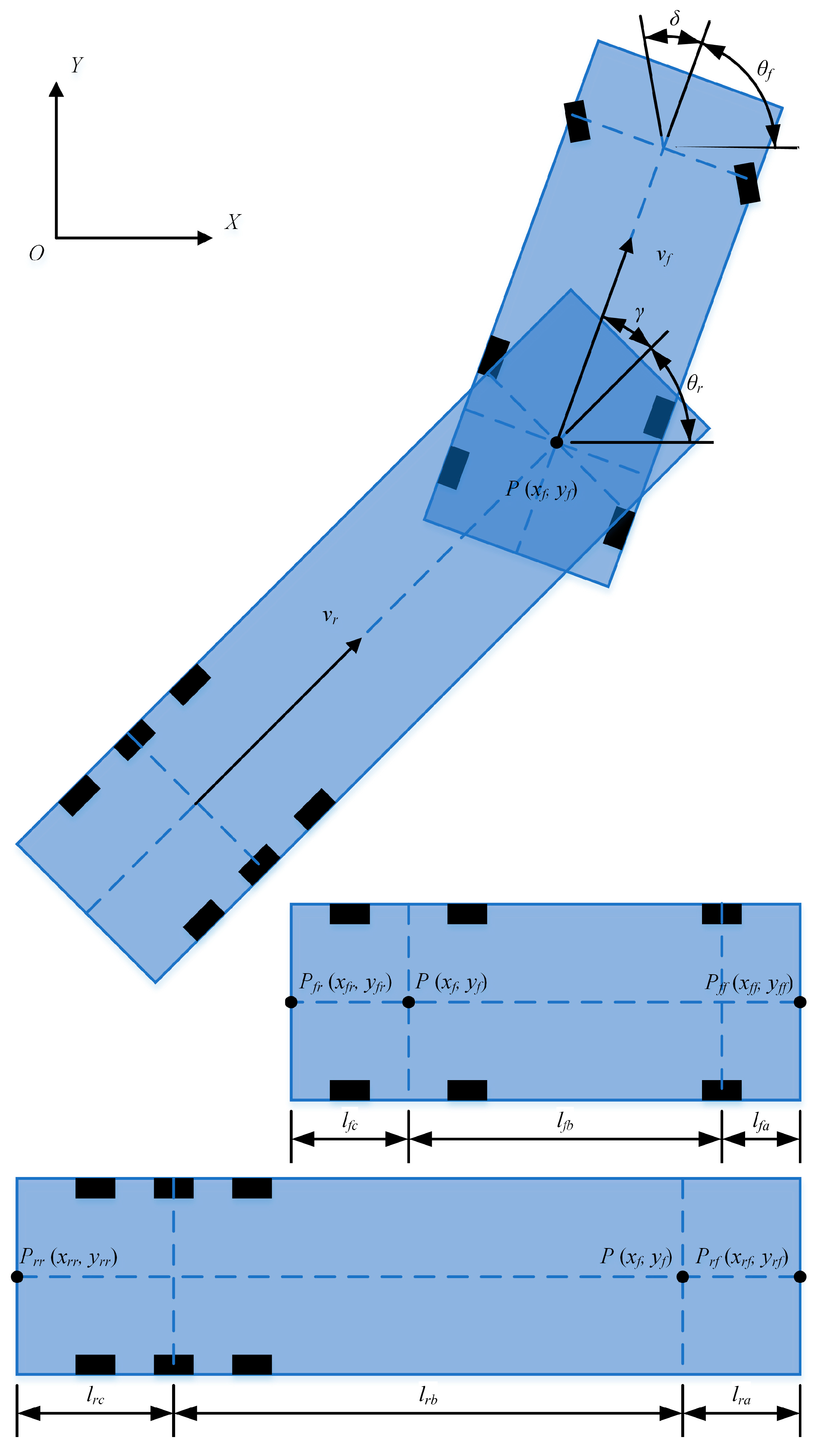
The semi-trailer consists of two bodies, of which the front body is the tractor and the rear body is the trailer. The kinematics model of the semi-trailer is shown in
Figure 1. The physical meanings of the parameters are shown in Notation.
In kinematic models, it is generally assumed that the vehicle meets non-holonomic constraints. Therefore, for the tractor, it can be considered that its equivalent rear axle, that is, the point
where the traction disc is located, has no lateral velocity:
where
,
, and
are the state of the tractor, and
vf and
δ are the control inputs.
Then, (1) can be rewritten as
According to the geometric relationship, the positions of
and
can be derived:
Since the velocities of the trailer and the tractor at point
are the same and the equivalent rear axle of the trailer is also assumed to be without lateral velocity, the following equation can be obtained:
where
.
According to the geometric relationship, the positions of
and
can be derived:
Combining the above formulations, the kinematics model of the semi-trailer can be concluded, as follows:
where
and
are the control inputs.
2.2. Obstacle Avoidance Model
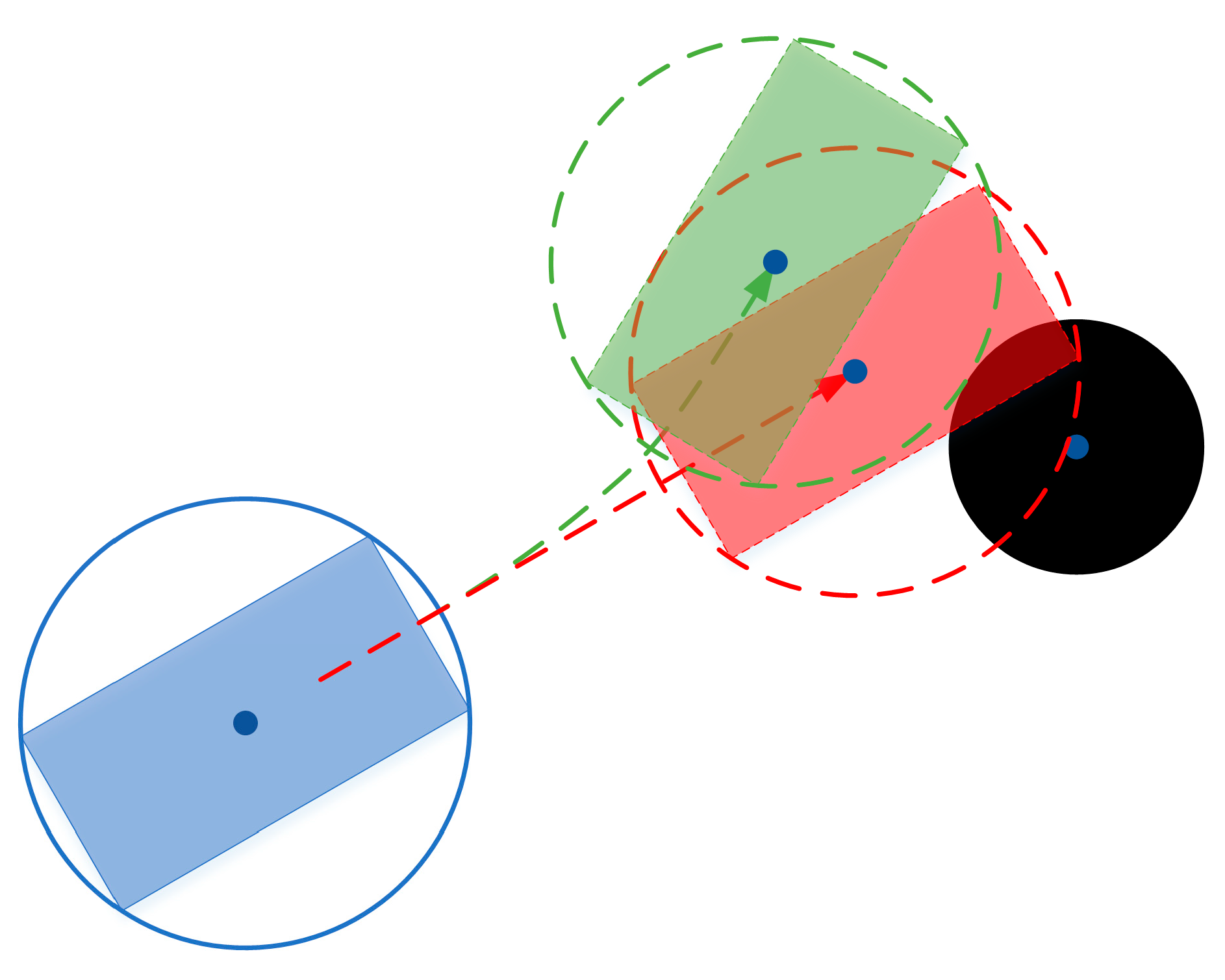
First, the principle of obstacle avoidance of the circumcircle model is introduced. In this paper, it is assumed that the obstacle is fixed, and the shape of the obstacle is a cylinder. So, we assume that, in the plane, the obstacle is a circle. In
Figure 2, the black circle is the obstacle. Its radius is equal to the sum of the radius of the obstacle and the safety margin. For the circumcircle obstacle avoidance model, the circumcircle overlaps with the obstacle circle; that is, the obstacle avoidance fails, as shown in the red trajectory in
Figure 2. The index for judging whether the circumcircle and the obstacle circle overlap is based on whether the distance between the center of the circumcircle and the center of the obstacle is greater than the sum of the radii of the two circles. Therefore, if the distance is less than the sum of the radii of the two circles, the penalty function will be set to a large value. Thus, the vehicle can be forced to travel along the green trajectory, thereby completing the obstacle avoidance. More details can be found in [
9,
14].
Figure 3 shows the circumcircle model of the semi-trailer, and the radius of the circumcircle is set to
Obviously, for semi-trailers, the radius of the circumcircle is much larger than the width of the vehicle, so this model will seriously reduce the passability of the semi-trailer. So, the model must be changed, but, as shown in
Figure 4, if we only reduce the radius of the circumcircle, it can increase the passability, but it may lead to obstacle avoidance failure. So, we propose a new model
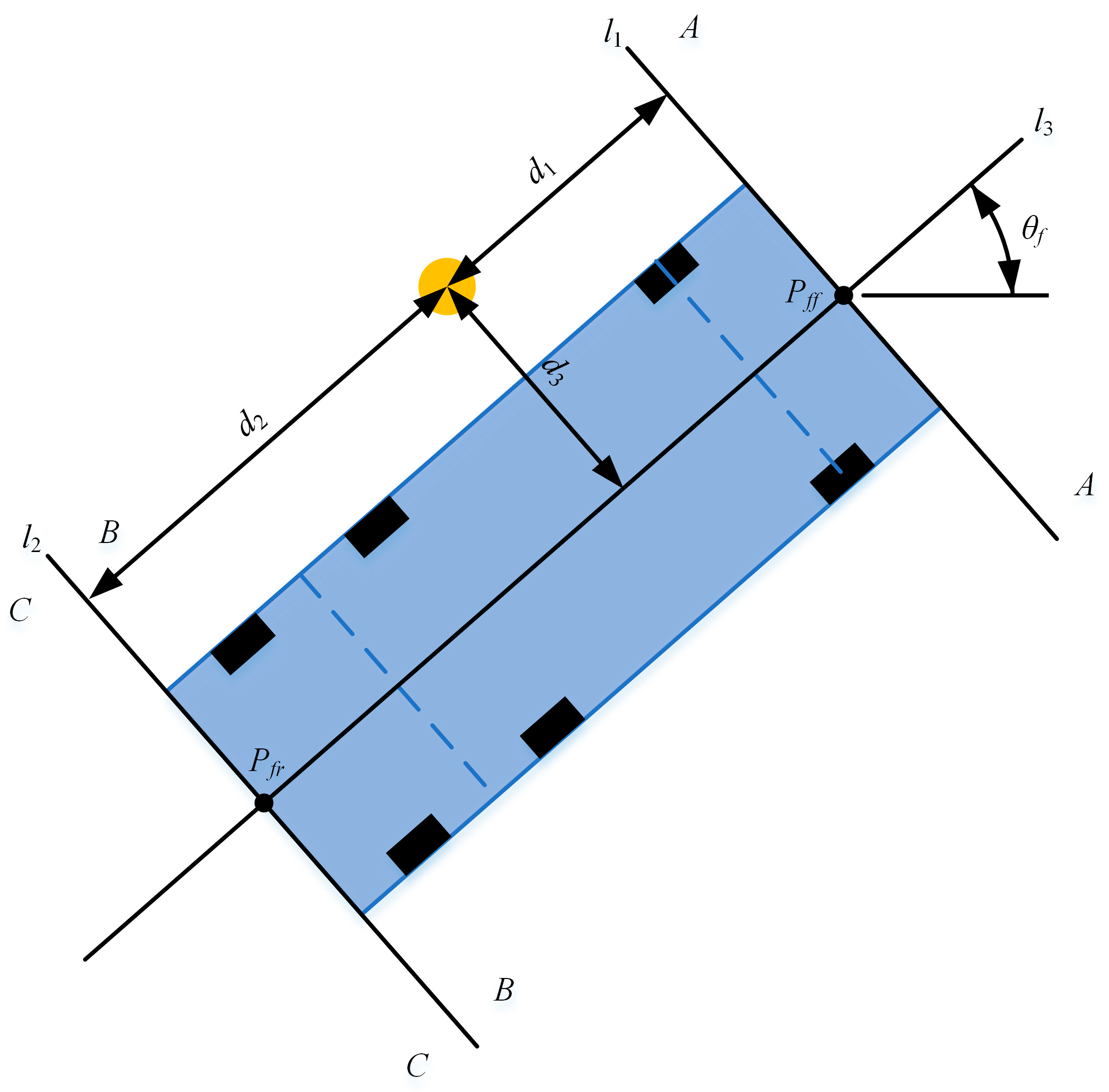
The semi-trailer consists of two bodies, so the obstacle avoidance model can also be built separately. For the tractor, the area around the body can be divided into three parts, as shown in
Figure 5. The physical meanings of the parameters are shown in Notation.
When the vehicle is moving forward, if the obstacle is in , the obstacle will be in in the future. Since the MPC controller can predict the state of the vehicle in a time domain, at a specific moment, the obstacle in can be ignored, and this obstacle will be considered in the prediction time domain. If the obstacle is in , it will not affect safety when the vehicle is moving forward. Therefore, the obstacle avoidance model only needs to express the situation that the obstacle is in .
Whether the obstacle is in
or not can be judged by the following formula:
Then, the following function can be set as the obstacle avoidance model according to the distance between the obstacle center and the middle line of the tractor:
where
where
is half the width of the semi-trailer,
is the radius of the obstacle, and
is the safety margin.
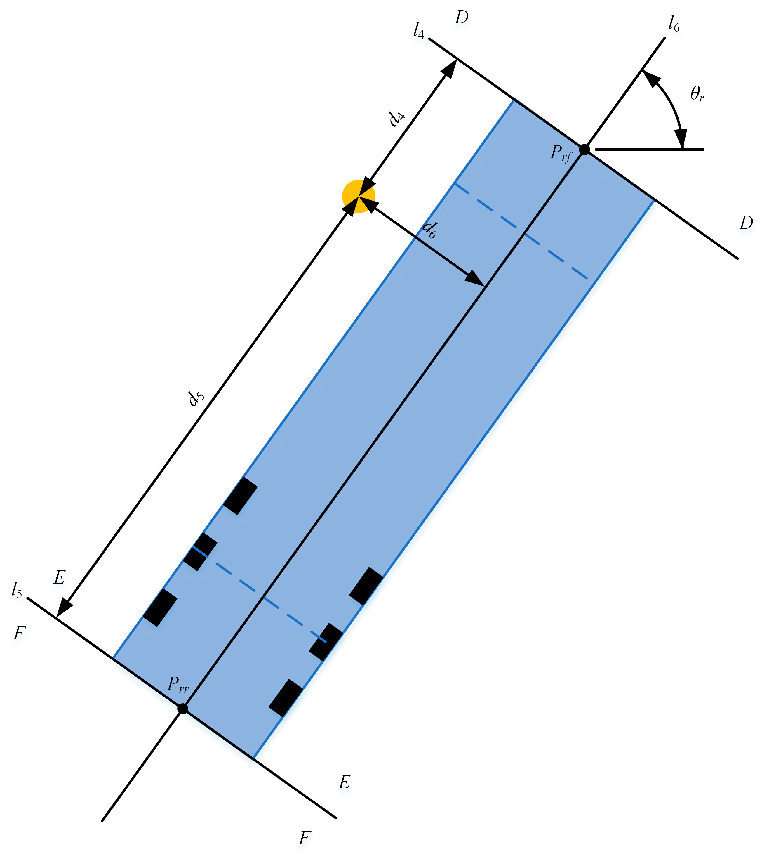
For the trailer, the same method can be used to establish the obstacle avoidance model. As shown in
Figure 6, the area around the body can be divided into
,
, and
, and the obstacle avoidance model only needs to express the situation where the obstacle is in
. The physical meanings of the parameters in
Figure 6 are shown in Notation. The final obstacle avoidance model for the trailer is shown as follows:
Combining (10) and (12), the obstacle avoidance model of the semi-trailer can be abbreviated as
3. MPC Controller Design
The MPC controller usually consists of two parts: the prediction model and the optimization function. Therefore, the design of the obstacle avoidance controller is also divided into two parts.
3.1. Prediction Model
The basis of the prediction model is the obstacle avoidance model.
For clarity, (7) is abstracted as
where
Since the control period is very small, (14) can be discretized by the Euler method as
where
is the control period,
represents the first predicted value of at time , and represents the first predicted inputs at time .
Then, the position and posture of the semi-trailer in the predicted time domain can be obtained:
where
is the prediction time domain and
is the control time domain.
From Notation, it can be obtained that
is a function of
.
where
.
So, (18) is the prediction model of the obstacle avoidance controller.
3.2. Optimization Function
Referring to [
9,
14,
15], the optimization function of the MPC-based obstacle avoidance controller needs to be merged into the same optimization formula with the optimization function of the MPC-based path tracking controller. Therefore, the optimization function can be designed as follows:
where
is the optimization function of the obstacle avoidance controller, and
is the optimization function of the path tracking controller.
Currently, there are some MPC-based controllers for the path tracking of vehicles [
22,
23,
24,
25,
26]. With reference to these papers, the optimization function of the MPC-based path tracking controller can be easily obtained. Therefore, the deduction process of
is no longer described in this paper.
is designed as
where
P is the weight matrix.
On this basis, we refer to the vehicle system constraints measured by Gong et al. [
27] and consider making the vehicle travel as smoothly as possible. Thus, the final optimization objective function is designed as
By solving (21), the following control sequence can be obtained:
where
is the next control input to the semi-trailer.
4. Simulation
The proposed obstacle avoidance controller was simulated by MATLAB/Simulink (MathWorks, Natick, MA, USA). The algorithm of the optimization solution used was the active-set in MATLAB. Since the obstacle position information can be set directly, the obstacle detection system was not included in the simulation system. In the real world, the obstacle position information can be obtained by laser radars or other sensors. The parameters in the simulation system are shown in
Table 1, where
Q and
R are the weight matrices of the optimization function of the path tracking control.
The proposed controller was compared with an obstacle avoidance controller based on a circumcircle model. The other parameters of this controller were the same as those of the proposed controller. In the simulation results, the controller proposed in this paper was named the controller based on the line model, and the other was named the controller based on the circumcircle model.
The simulation consisted of two groups. The purpose of the first group was to verify the performance of the two controllers when the obstacle was far from the reference path, and the purpose of the second group was to verify the performance when the obstacle was on the reference path.
4.1. First Group
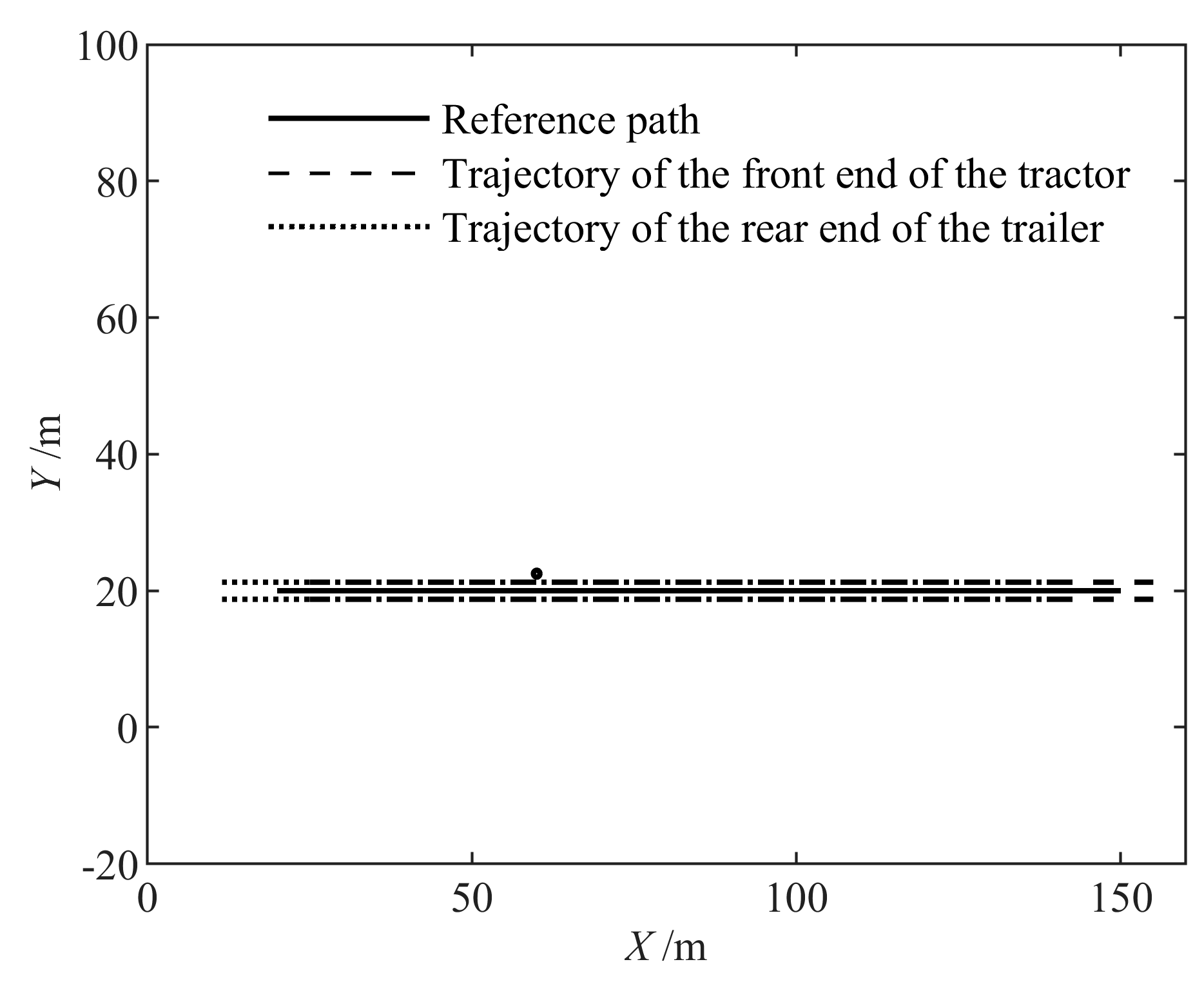
In this group of simulations, the direction of the reference path was the same as that of the -axis, and the obstacle was located to the left of the reference path at a distance of 2.5 m. This distance was greater than the sum of the half of the body width, the obstacle radius, and the safety margin. So, there was no need to avoid this obstacle.
Figure 7 shows the trajectory produced by the semi-trailer under the control of the proposed controller.
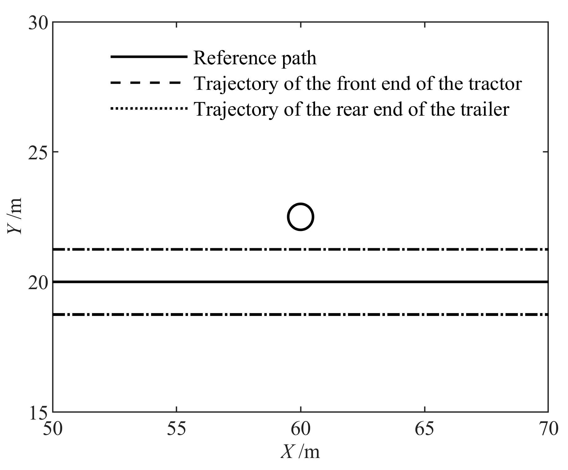
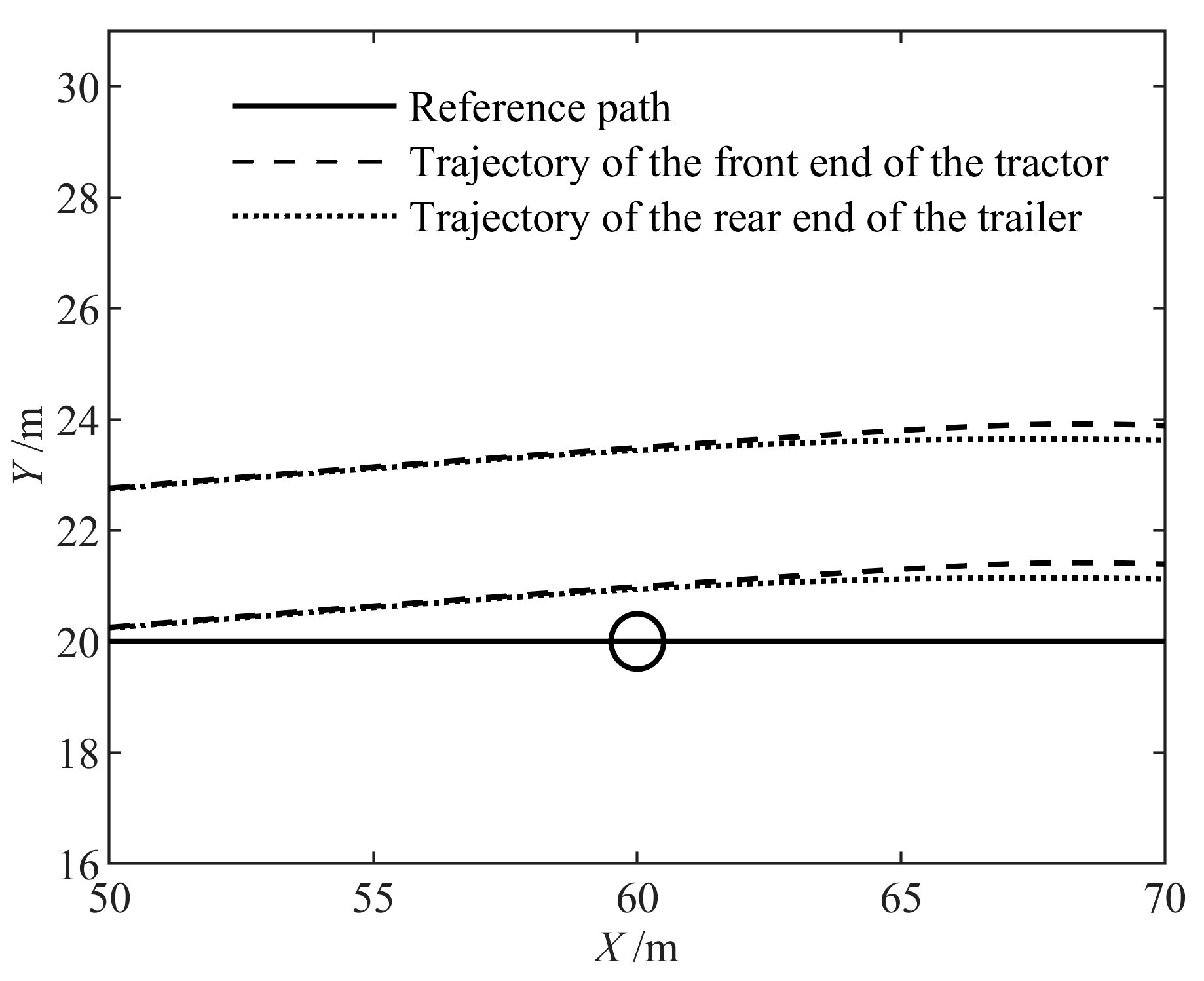
Figure 8 is a partially enlarged view of this trajectory. The trajectory shows that the proposed controller did not control the semi-trailer to leave the reference path. Additionally, the minimum value of the distance between the obstacle center and the trajectory of the semi-trailer was 1.2510 m. This value is larger than the sum of the obstacle radius and the safety margin.
Figure 9 shows the trajectory produced by the semi-trailer under the control of the controller based on the circumcircle model.
Figure 10 is a partially enlarged view of this trajectory. The trajectory indicates that this controller caused the semi-trailer to leave the reference path. Additionally, the minimum value of the distance between the obstacle center and the trajectory of the semi-trailer was 6.2015 m. This value is too big to be necessary.
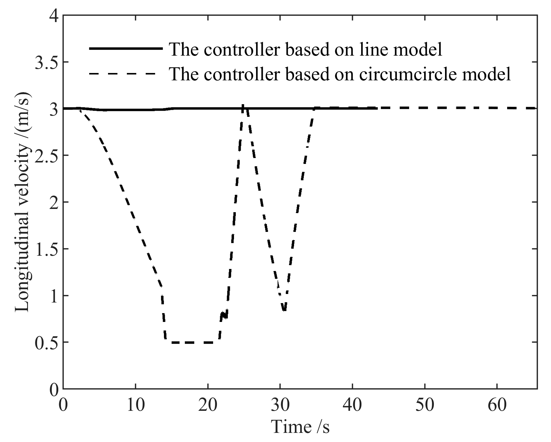
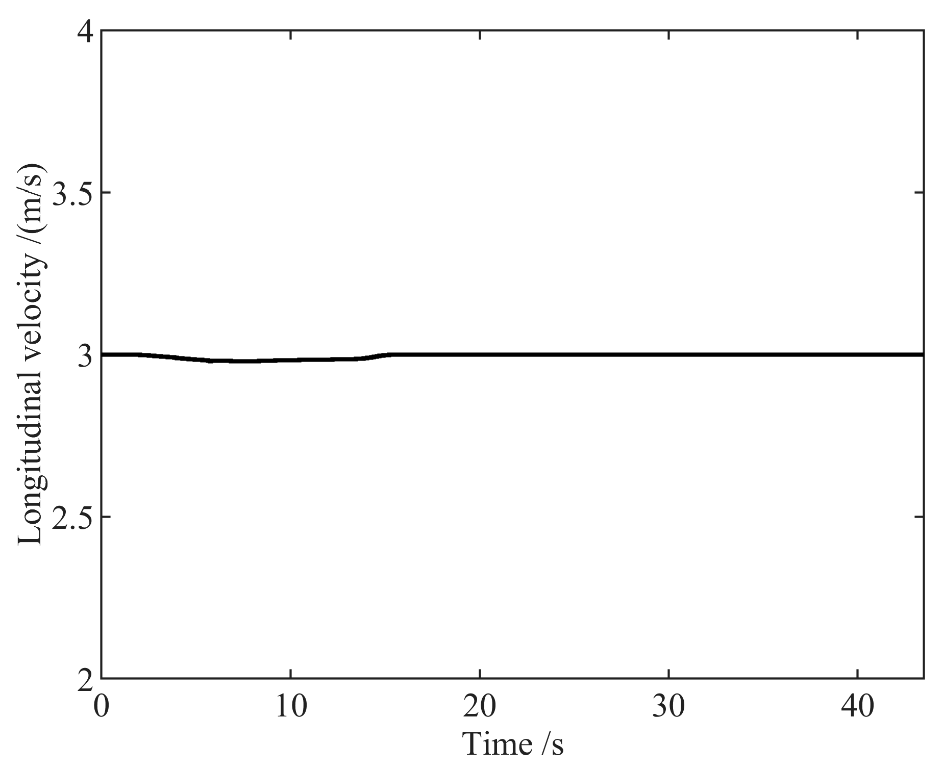
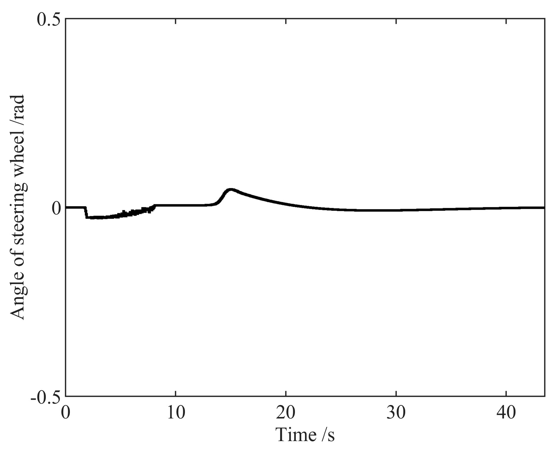
Figure 11 and
Figure 12 show the control inputs.
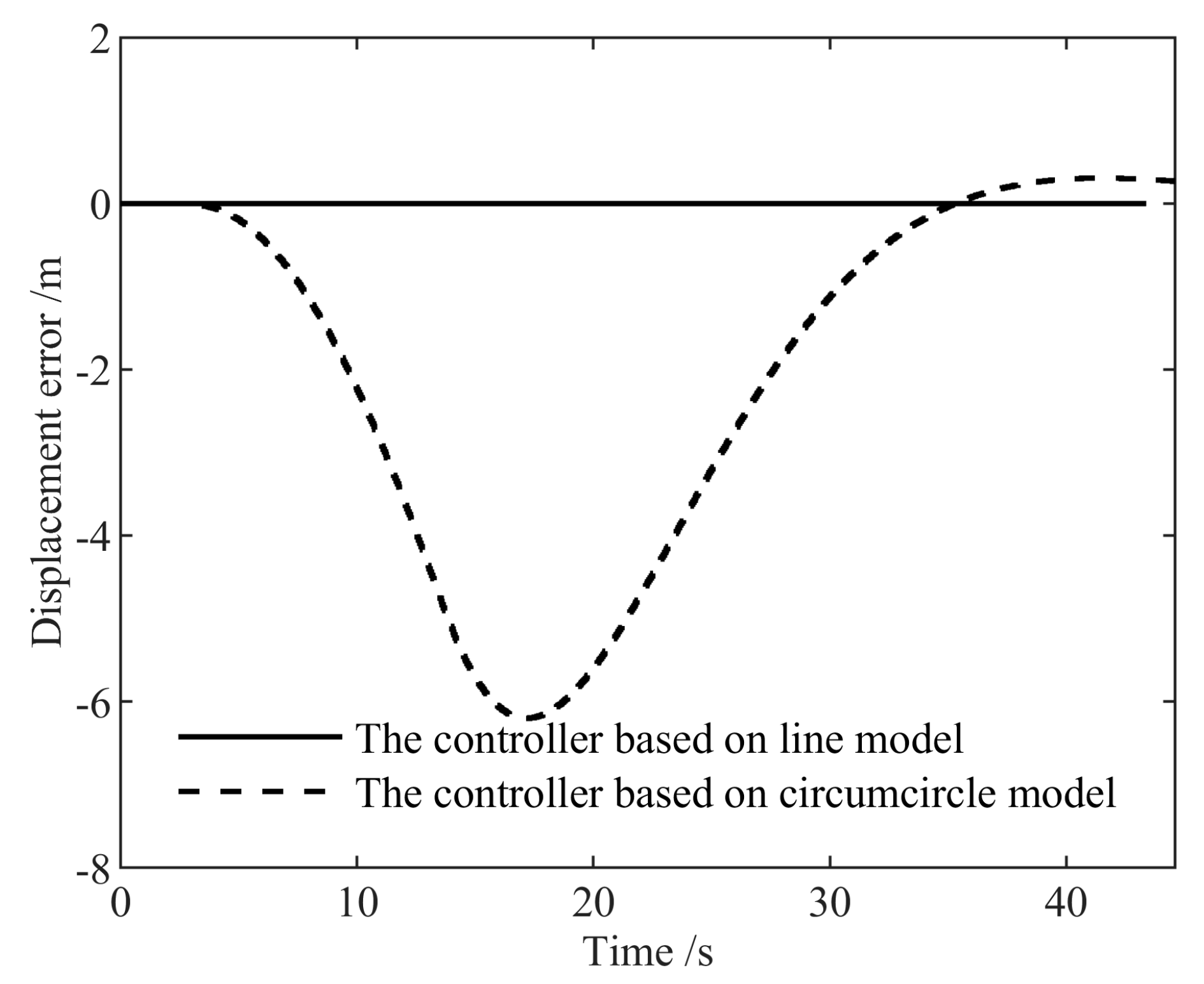
Figure 13 shows the displacement error between the midpoint of the rear axle of the tractor and the reference path. The maximum displacement error of the controller based on the circumcircle model was 6.2009 m. This value of the proposed controller was 0 m.
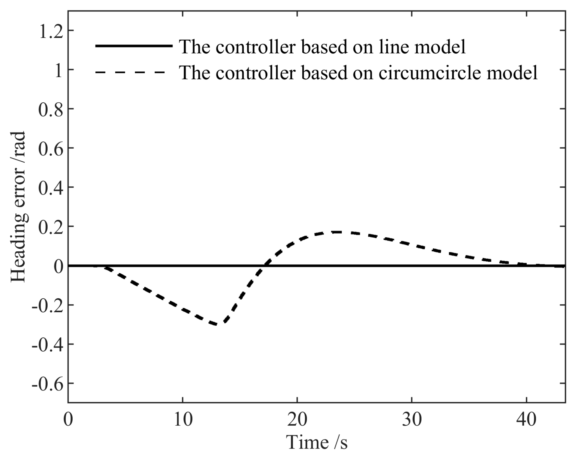
Figure 14 shows the heading error between the tractor and the reference path. The maximum heading error of the controller based on the circumcircle model was 0.3001 rad. The value of the proposed controller was 0 rad.
The above results show that the controller based on the circumcircle model greatly reduced the passable area of the semi-trailer. Additionally, the controller proposed in this paper was able to solve this problem. Compared with the controller based on the circumcircle model, the proposed controller reduced the displacement error and the heading error between the semi-trailer and the reference path by 6.2009 m and 0.3001 rad, respectively.
4.2. Second Group
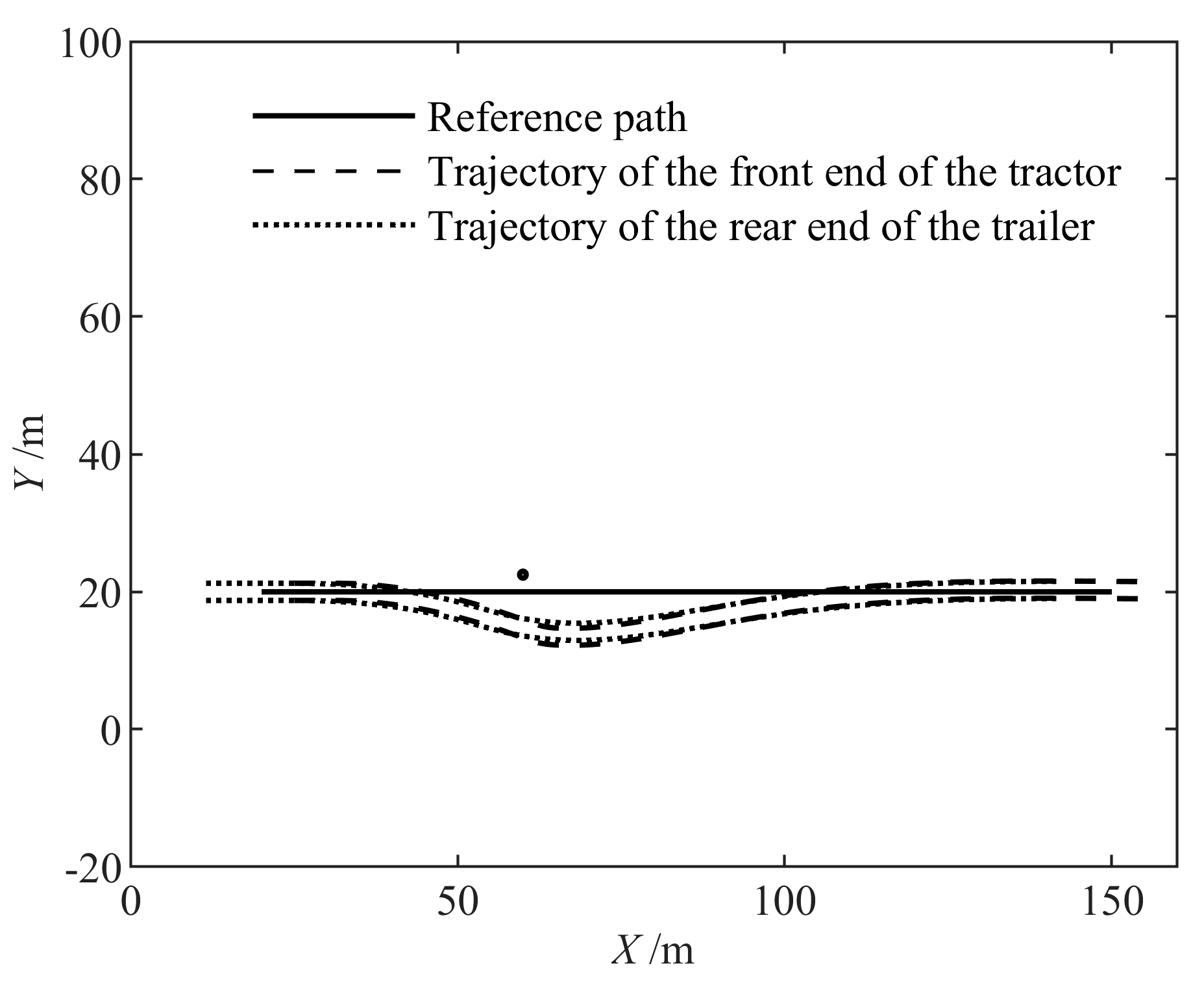
In this group of simulations, the reference path was the same as that of the previous group. The obstacle was on the reference path.
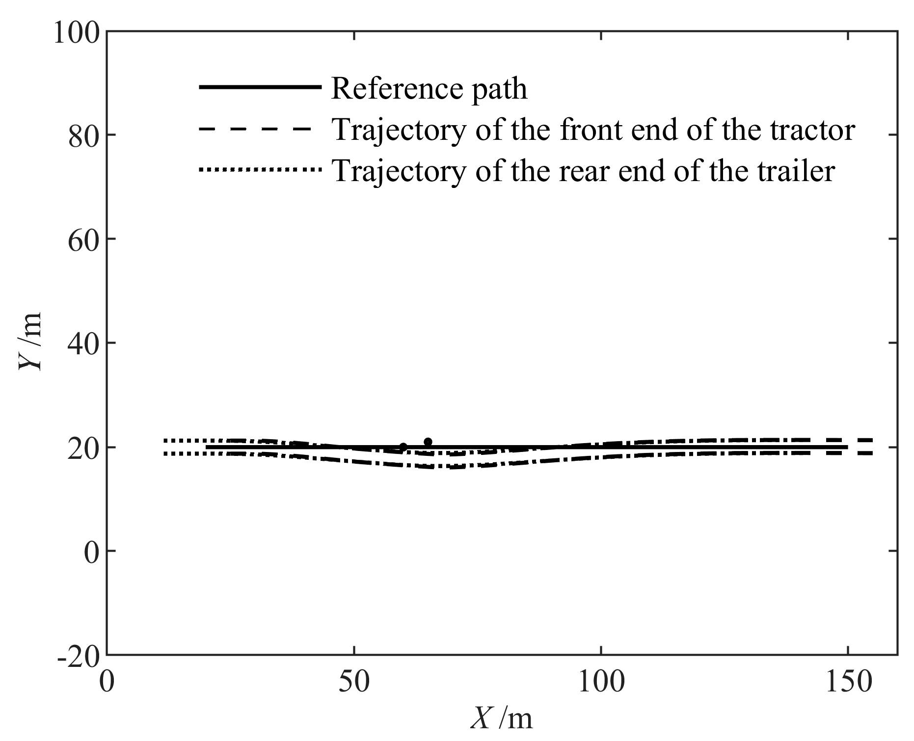
Figure 15 shows the trajectory produced by the semi-trailer under the control of the proposed controller.
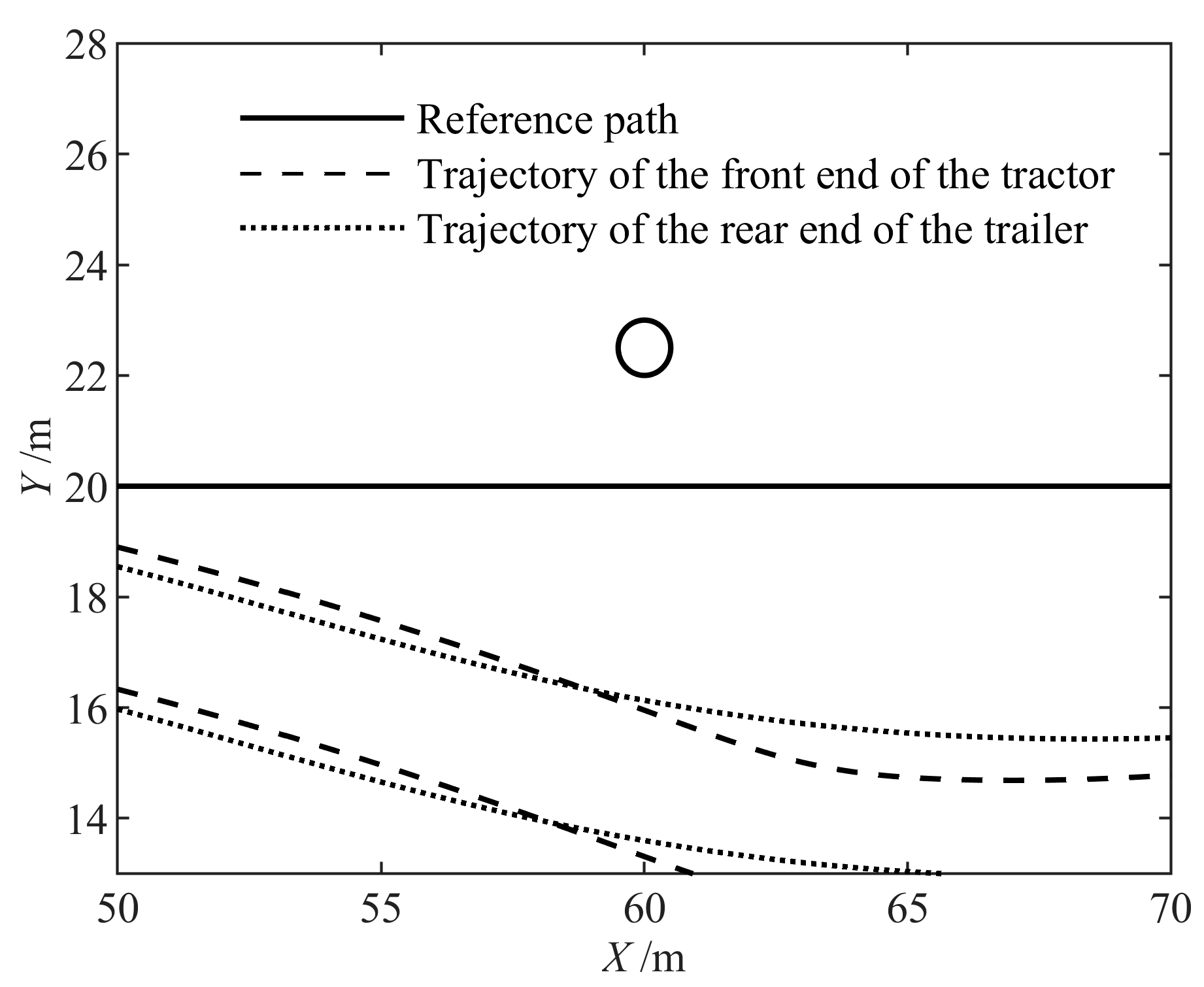
Figure 16 is a partially enlarged view of this trajectory. The trajectory shows that the proposed controller kept the semi-trailer away from the obstacle. The minimum value of the distance between the obstacle center and the trajectory of the semi-trailer was 0.9398 m. This value is larger than the sum of the obstacle radius and the safety margin.
Figure 17 shows the trajectory produced by the semi-trailer under the control of the controller based on the circumcircle model.
Figure 18 is a partially enlarged view of this trajectory. The trajectory shows that the controller based on the circumcircle model left the semi-trailer very far away from the reference path. The minimum value of the distance between the obstacle center and the trajectory of the semi-trailer was 1.9970 m. This value is too big to be necessary.
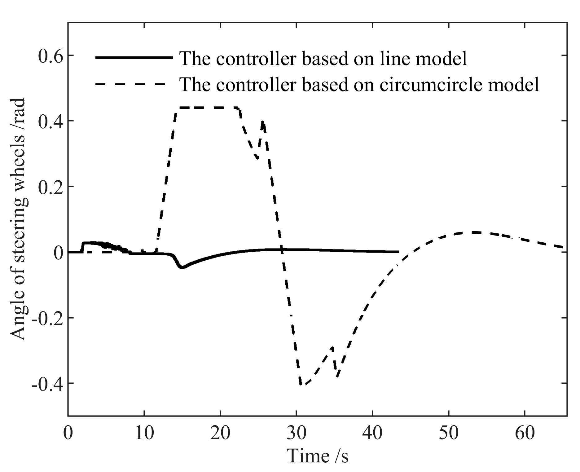
Figure 19 and
Figure 20 show the control inputs. With the proposed controller, the semi-trailer traveled more smoothly.
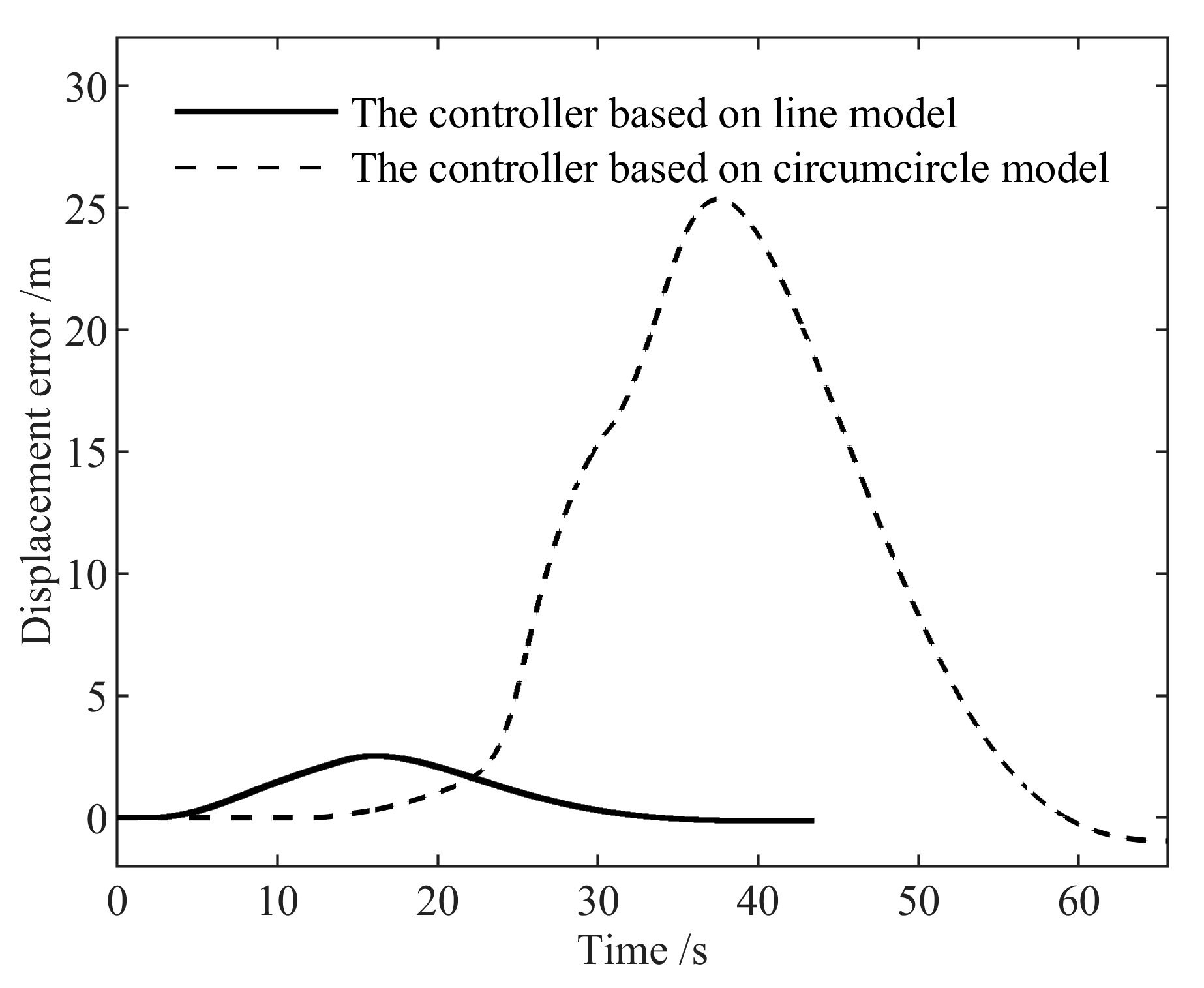
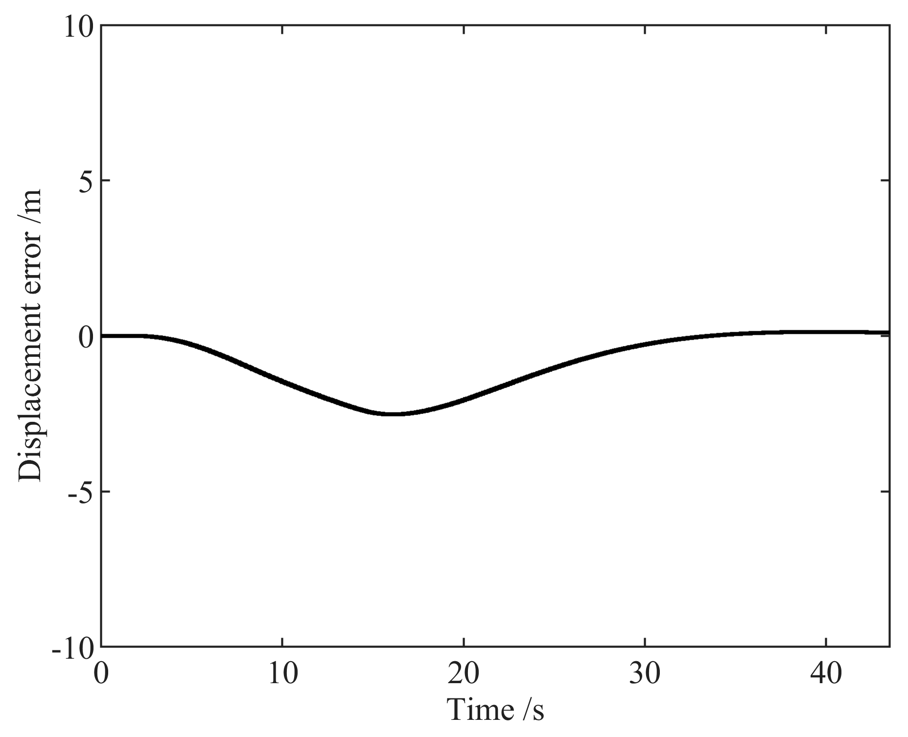
Figure 21 shows the displacement error between the midpoint of the rear axle of the tractor and the reference path. The maximum displacement error of the controller based on the circumcircle model was 25.3541 m. This value of the proposed controller was 2.5324 m.
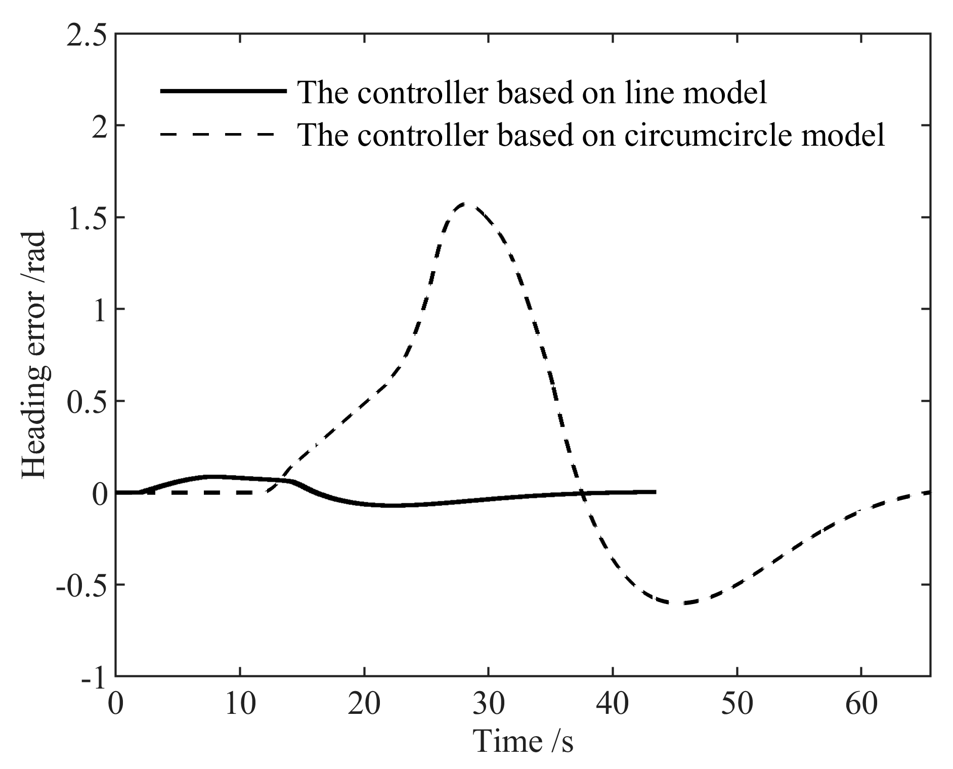
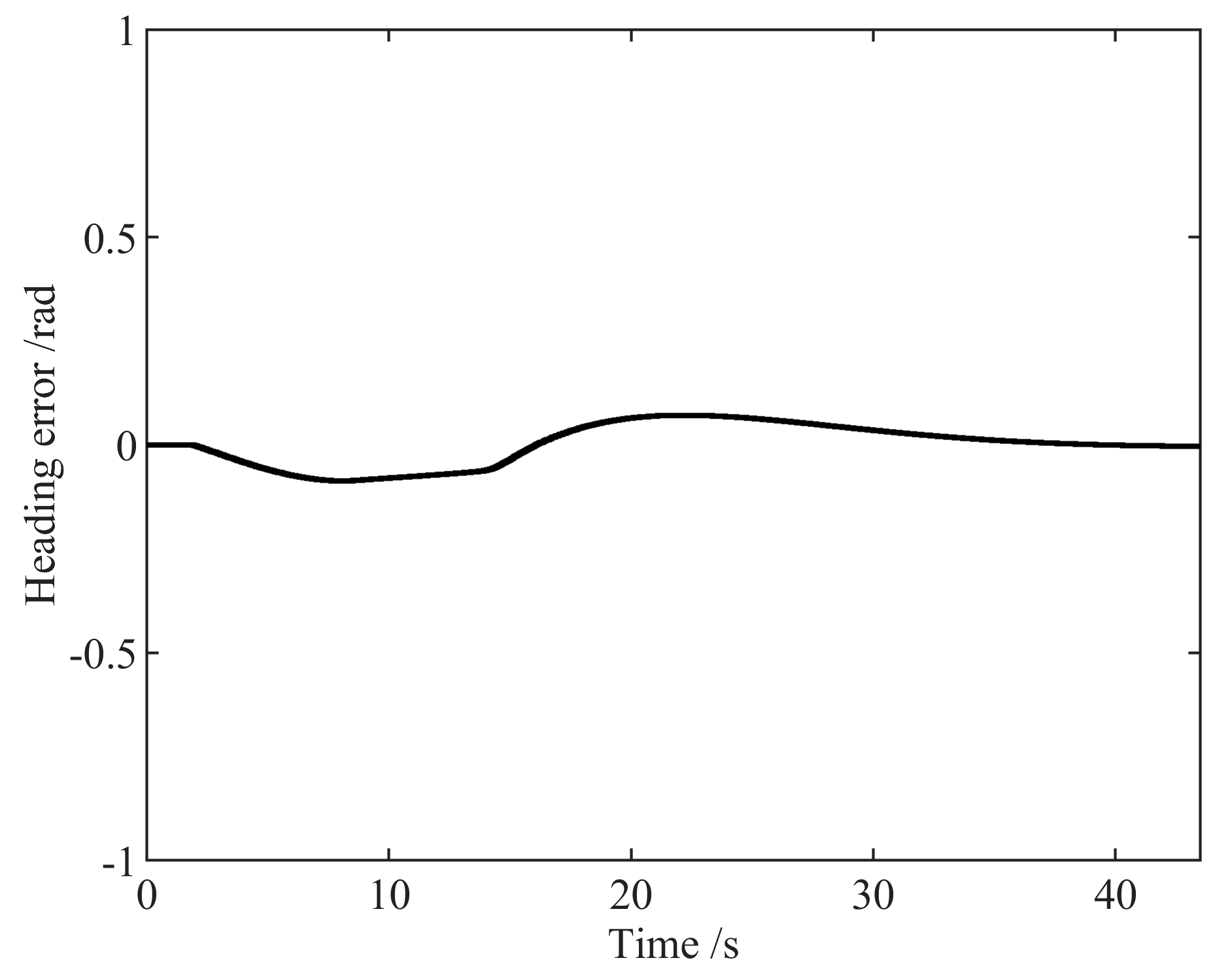
Figure 22 shows the heading error between the tractor and the reference path. The maximum heading error of the controller based on the circumcircle model was 1.5707 rad. This value of the proposed controller was 0.0866 rad.
Compared with the controller based on the circumcircle model, the proposed controller reduced the displacement error and the heading error between the semi-trailer and the reference path by 22.8217 m and 1.4841 rad, respectively.
4.3. Third Group
In this group of simulations, the reference path was the same as that used for the previous group. There were two obstacles in this set of simulations, and the first obstacle was on the reference path.
Figure 23 shows the trajectory produced by the semi-trailer under the control of the proposed controller.
Figure 24 is a partially enlarged view of this trajectory. The trajectory shows that the proposed controller kept the semi-trailer away from the obstacle. The minimum value of the distance between the obstacle center and the trajectory of the semi-trailer was 0.9419 m. This value is larger than the sum of the obstacle radius and the safety margin.
Figure 25 and
Figure 26 show the control inputs. With the proposed controller, the semi-trailer traveled more smoothly.
Figure 27 shows the displacement error between the midpoint of the rear axle of the tractor and the reference path. The maximum displacement error was 2.5253 m.
Figure 28 shows the heading error between the tractor and the reference path. The maximum heading error was 0.0872 rad. This set of simulation results shows that the obstacle avoidance controller is still effective when there are multiple obstacles.
5. Conclusions
Aiming at the obstacle avoidance control of the semi-trailer, we proposed a new obstacle avoidance model, and based on this model, an obstacle avoidance controller based on MPC was proposed. According to the simulation results, the following conclusions can be drawn.
Firstly, the controller proposed in this paper can ensure that there is no collision between the semi-trailer and the obstacle. In the simulation results, the minimum distance between the obstacle center and the body trajectory was 0.9398 m, which is greater than the sum of the obstacle radius and the safety margin.
Secondly, compared with the controller based on the circumcircle model, the proposed controller can reduce the error between the semi-trailer and the reference path during obstacle avoidance. In the simulation results, the displacement error was reduced by at least 6.2009 m, and the heading error was reduced by at least 0.3001 rad.
In addition, the simulation results show that although the controller based on the circumcircle model ensured no collision between the semi-trailer and the obstacle occurred, the semi-trailer was too far from the reference path during obstacle avoidance.
Taking into account the above conclusions, we think that the controller proposed in this paper is more suitable for the obstacle avoidance of semi-trailers than the traditional controller based on the circumcircle model.
Author Contributions
Conceptualization, G.B., C.L., and Y.M.; Methodology, G.B. and C.L.; Software, G.B.; Validation, G.B., and C.L.; Investigation, G.B.; Writing-original draft preparation, G.B. and C.L.; Writing-review and editing, Y.M., L.L., W.L., and Q.G.; Supervision, L.L. and W.L.; Project administration, L.L. and W.L.; Funding acquisition, L.L., W.L., Y.M., and Q.G.
Funding
This research was funded by the National Key Research and Development Program of China, grant number 2018YFC0604403 and 2016YFC0802905, the National High Technology Research and Development Program of China (863 program), grant number 2011AA060408 and the Fundamental Research Funds for the Central Universities, grant number FRF-TP-17-010A2.
Conflicts of Interest
The authors declare no conflict of interest. The funders had no role in the design of the study, in the collection, analyses, or interpretation of data, in the writing of the manuscript, or in the decision to publish the results.
Notation
| δ | The angle of the steering wheels of the semi-trailer |
| vf | The longitudinal velocity of the tractor |
| vr | The longitudinal velocity of the trailer |
| θf | Heading of the tractor |
| θr | Heading of the trailer |
| γ | The angle between the tractor and the trailer |
| P (xf, yf) | The midpoint of the equivalent rear axle of the tractor
The articulation point of the tractor and the trailer |
| Pff (xff, yff) | The midpoint of the front end of the tractor |
| Pfr (xfr, yfr) | The midpoint of the rear end of the tractor |
| Prf (xrf, yrf) | The midpoint of the front end of the trailer |
| Prr (xrr, yrr) | The midpoint of the rear end of the trailer |
| lfa | Distance between the front axle and the front end of the tractor |
| lfb | The wheelbase of the tractor |
| lfc | Distance between the rear axle and the rear end of the tractor |
| lra | Distance between the articulation point and the front end of the trailer |
| lrb | Distance between the articulation point and the axle of the trailer |
| lrc | Distance between the axle and the rear end of the trailer |
| A | The area in front of the tractor |
| B | The area on the side of the tractor |
| C | The area behind the tractor |
| l1 | The straight line perpendicular to the body at point Pff, the parametric formula of lines y = cot(θf)(x − xff) + yff |
| l2 | The straight line perpendicular to the body at point Pfr, the parametric formula of lines y = cot(θf)(x − xfr) + yfr |
| l3 | Middle line of the tractor, parametric formula of lines y = tan(θf)(x − xf) + yf |
| d1 | Distance between the obstacle center and l1 |
| d2 | Distance between the obstacle center and l2 |
| d3 | Distance between the obstacle center and l3 |
| D | The area in front of the trailer |
| E | The area on the side of the trailer |
| F | The area behind the trailer |
| l4 | The straight line perpendicular to the body at point Prf, the parametric formula of lines y = cot(θr)(x − xrf) + yrf |
| l5 | The straight line perpendicular to the body at point Pfr, the parametric formula of lines y = cot(θr)(x − xrr) + yrr |
| l6 | The middle line of the trailer, the parametric formula of lines y = tan(θr)(x − xf) + yf |
| d4 | Distance between the obstacle center and l4 |
| d5 | Distance between the obstacle center and l5 |
| d6 | Distance between the obstacle center and l6 |
References
- Larson, J. Off-Road Obstacle Classification and Traversability Analysis in the Presence of Negative Obstacles. Master’s Thesis, University of California, San Diego, CA, USA, 2011. [Google Scholar]
- Qiu, Q.; Yang, T.W.; Han, J.D. A new real-time algorithm for off-road terrain estimation using laser data. Sci. China Ser. F (Inf. Sci.) 2009, 52, 1658–1667. [Google Scholar] [CrossRef][Green Version]
- Yuan, J. Hierarchical motion planning for multi-steering tractor-trailer mobile robots with on-axle hitching. IEEE-ASME Trans. Mech. 2017, 22, 1652–1662. [Google Scholar] [CrossRef]
- Sgorbissa, A.; Zaccaria, R. Planning and obstacle avoidance in mobile robotics. Robot. Auton. Syst. 2012, 60, 628–638. [Google Scholar] [CrossRef]
- Fahimi, F.; Nataraj, C.; Ashrafiuon, H. Real-time obstacle avoidance for multiple mobile robots. Robotica 2009, 27, 189–198. [Google Scholar] [CrossRef]
- Maciejowski, J.M. Introduction. In Predictive Control: With Constraints; Pearson Education: New York, NY, USA, 2002; pp. 1–32. [Google Scholar]
- Yoon, Y.; Shin, J.; Kim, H.J.; Park, Y.; Sastry, S. Model-predictive active steering and obstacle avoidance for autonomous ground vehicles. Control Eng. Pract. 2009, 17, 741–750. [Google Scholar] [CrossRef]
- Frasch, J.V.; Gray, A.; Zanon, M.; Ferreau, H.J. An auto-generated nonlinear MPC algorithm for real-time obstacle avoidance of ground vehicles. In Proceedings of the 2013 European Control Conference, Zurich, Switzerland, 17–19 July 2013. [Google Scholar] [CrossRef]
- Gong, J.W.; Jiang, Y.; Xu, W. Trajectory tracking control with planning layer. In Model Predictive Control for Self-Driving Vehicles; Beijing Institute of Technology Press: Beijing, China, 2014; Chapter 6; pp. 134–170. (In Chinese) [Google Scholar]
- Nayl, T.; Nikolakopoulos, G.; Gustafsson, T. Effect of kinematic parameters on MPC based on-line motion planning for an articulated vehicle. Robot. Auton. Syst. 2015, 70, 16–24. [Google Scholar] [CrossRef]
- Wang, M.; Luo, J.; Walter, U. A non-linear model predictive controller with obstacle avoidance for a space robot. Adv. Space Res. 2016, 57, 1737–1746. [Google Scholar] [CrossRef]
- Liu, J.; Jayakumar, P.; Stein, J.L.; Ersal, T. A double-worst-case formulation for improving the robustness of an MPC-based obstacle avoidance algorithm to parametric uncertainty. In Proceedings of the 2017 American Control Conference, Seattle, WA, USA, 24–26 May 2017. [Google Scholar] [CrossRef]
- Liu, J.; Jayakumar, P.; Stein, J.L.; Ersal, T. Combined speed and steering control in high-speed autonomous ground vehicles for obstacle avoidance using model predictive control. IEEE Trans. Veh. Technol. 2017, 66, 8746–8763. [Google Scholar] [CrossRef]
- Hua, X.F.; Duan, J.M.; Tian, X.S. Research on vehicle obstacle avoidance based on restricted areas penalty function and MPC prediction multiplication. Comput. Eng. Appl. 2018, 54, 131–138. (In Chinese) [Google Scholar]
- Bai, G.; Liu, L.; Meng, Y.; Luo, W.; Gu, Q.; Liang, C. Study of obstacle avoidance controller of agricultural tractor-trailers based on predictive control of nonlinear model. Trans. Chin. Soc. Agric. Mach. 2019, 50, 356–362. (In Chinese) [Google Scholar] [CrossRef]
- Zong, C.; Zhu, T.; Wang, C.; Liu, H. Multi-objective stability control algorithm of heavy tractor semi-trailer based on differential braking. Chin. J. Mech. Eng. 2012, 25, 88–97. [Google Scholar] [CrossRef]
- Lima, P.F.; Nilsson, M.; Trincavelli, M.; Martensson, J.; Wahlberg, B. Spatial model predictive control for smooth and accurate steering of an autonomous truck. IEEE Trans. Intell. Veh. 2017, 2, 238–250. [Google Scholar] [CrossRef]
- Wu, T.; Hung, J.Y. Path following for a tractor-trailer system using model predictive control. In Proceedings of the SoutheastCon 2017, Charlotte, NC, USA, 30 March–2 April 2017. [Google Scholar] [CrossRef]
- Nayl, T.; Nikolakopoulos, G.; Gustafsson, T. A full error dynamics switching modeling and control scheme for an articulated vehicle. Int. J. Control Autom. 2015, 13, 1221–1232. [Google Scholar] [CrossRef]
- Bin, Y.; Shim, T. Constrained model predictive control for backing-up tractor-trailer system. In Proceedings of the 10th World Congress on Intelligent Control and Automation, Beijing, China, 6–8 July 2012. [Google Scholar] [CrossRef]
- Astolfi, A.; Bolzern, P.; Locatelli, A. Path-tracking of a tractor-trailer vehicle along rectilinear and circular paths: A Lyapunov-based approach. IEEE Trans. Robot. Autom. 2004, 20, 154–160. [Google Scholar] [CrossRef]
- Backman, J.; Oksanen, T.; Visala, A. Navigation system for agricultural machines: Nonlinear model predictive path tracking. Comput. Electron. Agric. 2012, 82, 32–43. [Google Scholar] [CrossRef]
- Kraus, T.; Ferreau, H.J.; Kayacan, E.; Ramon, H.; De Baerdemaeker, J.; Diehl, M.; Saeys, W. Moving horizon estimation and nonlinear model predictive control for autonomous agricultural vehicles. Comput. Electron. Agric. 2013, 98, 25–33. [Google Scholar] [CrossRef]
- Oyelere, S.S. The application of model predictive control (MPC) to fast systems such as autonomous ground vehicles (AGV). IOSR J. Comput. Eng. 2014, 16, 27–37. [Google Scholar] [CrossRef]
- Kayacan, E.; Kayacan, E.; Ramon, H.; Saeys, W. Learning in centralized nonlinear model predictive control: Application to an autonomous tractor-trailer system. IEEE Trans. Control Syst. Technol. 2015, 23, 197–205. [Google Scholar] [CrossRef]
- Du, X.; Htet, K.K.K.; Tan, K.K. Development of a genetic-algorithm-based nonlinear model predictive control scheme on velocity and steering of autonomous vehicles. IEEE Trans. Ind. Electron. 2016, 63, 6970–6977. [Google Scholar] [CrossRef]
- Gong, J.W.; Xu, W.; Jiang, Y.; Liu, K.; Guo, H.F.; Sun, Y.J. Multi-constrained model predictive control for autonomous ground vehicle trajectory tracking. J. Beijing. Inst. Technol. 2015, 24, 441–443. [Google Scholar]
Figure 1.
The kinematics model of the semi-trailer.
Figure 1.
The kinematics model of the semi-trailer.
Figure 2.
Schematic diagram of the circumcircle model for obstacle avoidance.
Figure 2.
Schematic diagram of the circumcircle model for obstacle avoidance.
Figure 3.
The circumcircle model of the semi-trailer.
Figure 3.
The circumcircle model of the semi-trailer.
Figure 4.
Schematic diagram of the challenge of the circle model.
Figure 4.
Schematic diagram of the challenge of the circle model.
Figure 5.
The obstacle avoidance model of the tractor.
Figure 5.
The obstacle avoidance model of the tractor.
Figure 6.
The obstacle avoidance model of the trailer
Figure 6.
The obstacle avoidance model of the trailer
Figure 7.
The trajectory of the obstacle avoidance controller based on the line model in the first group of simulations.
Figure 7.
The trajectory of the obstacle avoidance controller based on the line model in the first group of simulations.
Figure 8.
Partially enlarged view of
Figure 7.
Figure 8.
Partially enlarged view of
Figure 7.
Figure 9.
The trajectory of the obstacle avoidance controller based on the circumcircle model in the first group of simulations.
Figure 9.
The trajectory of the obstacle avoidance controller based on the circumcircle model in the first group of simulations.
Figure 10.
Partially enlarged view of
Figure 9.
Figure 10.
Partially enlarged view of
Figure 9.
Figure 11.
Longitudinal velocity in the first group of simulations.
Figure 11.
Longitudinal velocity in the first group of simulations.
Figure 12.
The angle of steering wheels in the first group of simulations.
Figure 12.
The angle of steering wheels in the first group of simulations.
Figure 13.
Displacement error between P and the reference path in the first group of simulations.
Figure 13.
Displacement error between P and the reference path in the first group of simulations.
Figure 14.
Heading error between the tractor and the reference path in the first group of simulations.
Figure 14.
Heading error between the tractor and the reference path in the first group of simulations.
Figure 15.
The trajectory of the obstacle avoidance controller based on the line model in the second group of simulations.
Figure 15.
The trajectory of the obstacle avoidance controller based on the line model in the second group of simulations.
Figure 16.
Partially enlarged view of
Figure 15.
Figure 16.
Partially enlarged view of
Figure 15.
Figure 17.
The trajectory of the obstacle avoidance controller based on the circumcircle model in the second group of simulations.
Figure 17.
The trajectory of the obstacle avoidance controller based on the circumcircle model in the second group of simulations.
Figure 18.
Partially enlarged view of
Figure 17.
Figure 18.
Partially enlarged view of
Figure 17.
Figure 19.
Longitudinal velocity in the second group of simulations.
Figure 19.
Longitudinal velocity in the second group of simulations.
Figure 20.
The angles of steering wheels in the second group of simulations.
Figure 20.
The angles of steering wheels in the second group of simulations.
Figure 21.
Displacement error between P and the reference path in the second group of simulations.
Figure 21.
Displacement error between P and the reference path in the second group of simulations.
Figure 22.
Heading error between the tractor and the reference path in the second group of simulations.
Figure 22.
Heading error between the tractor and the reference path in the second group of simulations.
Figure 23.
The trajectory of the obstacle avoidance controller based on the line model in the third group of simulations.
Figure 23.
The trajectory of the obstacle avoidance controller based on the line model in the third group of simulations.
Figure 24.
Partially enlarged view of
Figure 23.
Figure 24.
Partially enlarged view of
Figure 23.
Figure 25.
Longitudinal velocity in the third group of simulations.
Figure 25.
Longitudinal velocity in the third group of simulations.
Figure 26.
The angle of steering wheels in the third group of simulations.
Figure 26.
The angle of steering wheels in the third group of simulations.
Figure 27.
Displacement error between P and the reference path in the third group of simulations.
Figure 27.
Displacement error between P and the reference path in the third group of simulations.
Figure 28.
Heading error between the tractor and the reference path in the third group of simulations.
Figure 28.
Heading error between the tractor and the reference path in the third group of simulations.
Table 1.
The parameters in the simulation system.
Table 1.
The parameters in the simulation system.
| Parameter | Value | Parameter | Value | Parameter | Value |
|---|
| lfa | 1 m | lb | 1.25 m | P | 100,000 I |
| lfb | 4 m | lr | 0.5 m | Q | 10 I |
| lfc | 1.5 m | ls | 0.45 m | R | 0.01 I |
| lra | 1.5 m | T | 0.05 s | I | identity matrix |
| lrb | 6.5 m | Np | 200 | | |
| lrc | 2 m | Nc | 1 | | |
© 2019 by the authors. Licensee MDPI, Basel, Switzerland. This article is an open access article distributed under the terms and conditions of the Creative Commons Attribution (CC BY) license (http://creativecommons.org/licenses/by/4.0/).
