1. Introduction
Due to the problems of wear and spark of the brush and slip ring, applications of conventional electrically excited synchronous motors (EESMs) are limited. Brushless rotor excitation is an important development direction of the EESM. Based on the principle of inductive coupling, some scholars have made beneficial explorations in this direction. Zhang et al. proposed a brushless doubly fed machine and studied its electromagnetic characteristics [
1]. Xia and Huang proposed dual windings in the rotor side of the synchronous generator to provide the excitation current by capturing the harmonics of the stator armature current through harmonic induction windings [
2]. Liu et al. presented a brushless power transferring approach through a high frequency rotating exciter, designed a 48 V 20 kW brushless EESM for mild hybrid vehicles, and studied its torque–speed characteristics, efficiency, copper loss, and temperature rise [
3,
4,
5,
6]. Hu et al. also designed a brushless EESM [
7]. However, the efficiency of the conventional rotor brushless excitation method is low.
In addition, a contactless power transfer system based on capacitive coupling was proposed. Ludois et al. designed a wound field synchronous machine base on the principle of capacitive coupling and studied its performance [
8,
9,
10,
11]. However, its structure is complex and its axial dimension is large.
In 2007, Kurs et al. proposed a magnetic resonance coupling wireless power transfer (MRC-WPT) scheme [
12], which enriched the technical scheme of wireless power transfer schemes. Jiang et al. proposed and implemented the concept of time-division multiplexing wireless power transfer for separately excited DC motor drives [
13]. Ditze et al. examined an inductive power transfer system with a rotary transformer as an alternative solution to slip ring systems for a contactless energy transfer to rotating equipment [
14].
This paper applies the principle of MRC-WPT to the rotor excitation of EESM. A rotor resonant wireless excitation system of EESM is designed. This paper explores the rotor field oriented control (RFOC) of resonant wireless EESM (RW-EESM).
2. Principle of MRC-WPT
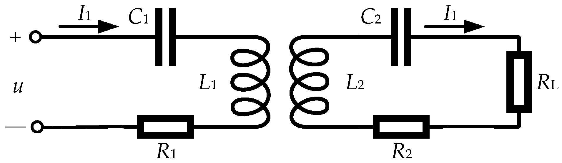
Taking the inductor/capacitor-inductor/capacitor (LC-LC) topology as an example, the principle of MRC-WPT is shown in
Figure 1.
u is the AC excitation voltage on the primary side.
L1 and
C1 are the inductor and capacitor on the primary side, respectively.
R1 is the parasitic resistance on the primary side.
L2 and
C2 are the inductor and capacitor on the secondary side, respectively.
R2 and
RL are the parasitic and load resistances on the primary side, respectively.
M is the mutual inductance of primary and secondary coils.
I1 and
I2 are the currents on the primary and secondary sides, respectively. The primary side and the secondary side are isolated from each other in space, and there is no contact. Coupling is achieved by mutual inductance between the primary side and secondary side coils.
When the primary and secondary sides all operate at the resonant frequency, the resonant frequency is:
In the case of power transfer, the resonant frequencies of primary and secondary sides should be equal. The efficiency of power transfer is expressed as:
R2 is much smaller than
RL, so
From Equation (3), it can be seen that the efficiency increases with the increase of mutual inductance and resonant frequency. For the motor rotor excitation, the distance of power transfer is short. Thus, the mutual inductance can be designed to be larger, and the resonant frequency can be designed to be higher. Furthermore, the efficiency of power transfer can be theoretically high.
3. A Resonant Wireless Excitation System of EESM
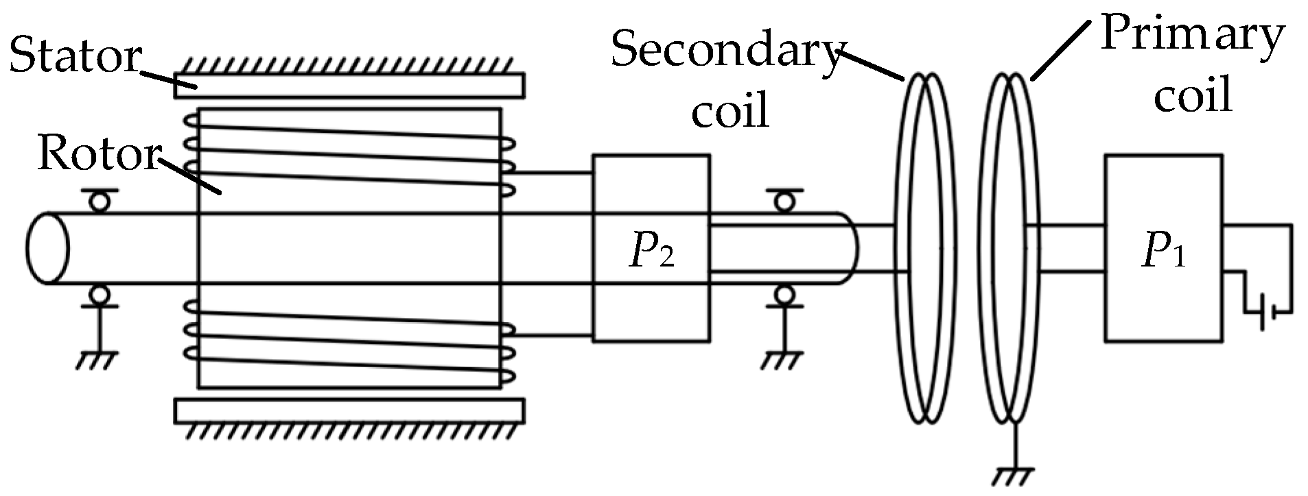
3.1. The Type of Primary and Secondary Coils
The primary coil is fixed to the stator, and the secondary coil is connected to the rotor. The relative position of the two coils should be consistent to ensure that the mutual inductance is constant, so that the characteristics of power transfer do not change. The two coils can be designed as circular rings, and the coils are in two planes perpendicular to the rotor axis, as shown in
Figure 2.
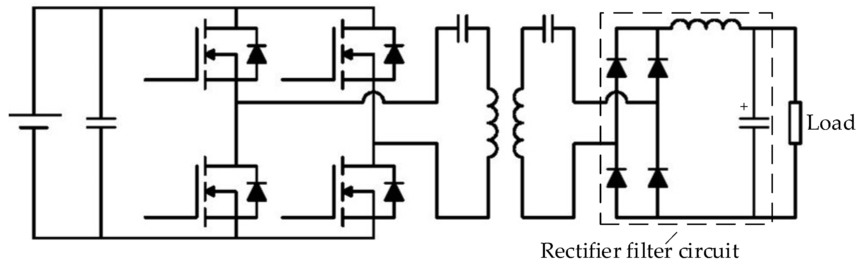
3.2. The Secondary Circuit
The power transferred to the secondary coil is AC, but the EESM rotor needs DC power. Hence, it is necessary to convert the AC power to DC power at the secondary side through rectification and filtering. A feasible rectifier filter circuit is shown in
Figure 3. The secondary circuit is rectified by a full bridge and filtered by an inductor and a capacitor to obtain DC power, which is then used to excite the rotor coil.
3.3. The Voltage at the Primary Side
The primary excitation is theoretically a sinusoidal voltage. However, the primary excitation is an easily implemented square wave in practice. In the square wave, besides the main fundamental wave of energy transfer, there are also harmonics, such as 3th/5th/7th harmonics. The amplitude of the harmonics decreases rapidly with the increase of harmonic order. Furthermore, the MRC-WPT system has a strong band-pass characteristic. Harmonics have little effect on the energy transfer, so the harmonic effect can be ignored. The sinusoidal voltage can be replaced with a square wave.
3.4. Rotor Excitation Current Regulation
When the motor runs under different conditions, the demand of rotor excitation current may be different, which can be realized by adjusting the voltage at the primary side. For a certain system, when other parameters are all determined, the power on the load can only be adjusted by the amplitude of voltage at the primary side. In practice, changing the duty ratio cycle of the square wave can adjust the amplitude of voltage, and further control the rotor excitation current.
4. Model of EESM and RFOC
4.1. Model of EESM
Taking a three-phase salient pole EESM as an example, the assumptions are as follows. The stator three-phase windings are symmetrically distributed in space. The air gap magnetic field is sinusoidally distributed in space. The influence of magnetic saturation, core loss, and temperature change on the motor is neglected. The normal direction is set by the motor practice.
The axis of rotor excitation winding is called the direct axis (d-axis), and its orthogonal axis is called the quadrature axis (q-axis). In the rotor direct-quadrature (dq) synchronous coordinate system, the stator and rotor voltage equations are:
where
Rs and
Rf are the stator and rotor winding resistances, respectively;
id and
iq are the current components of the stator on the d-axis and q-axis, respectively;
if is the rotor excitation current;
and
are the flux components of the stator on the d-axis and q-axis, respectively;
is the rotor flux; and
is the electrical angular velocity of the rotor.
where
Ld and
Lq are the inductance components of the stator on the d-axis and q-axis, respectively.
Lf is the self inductance of the rotor.
Lmd is the mutual inductance on the d-axis.
The torque of EESM is
where
p0 is the pole number of the motor. From Equations (11) and (12):
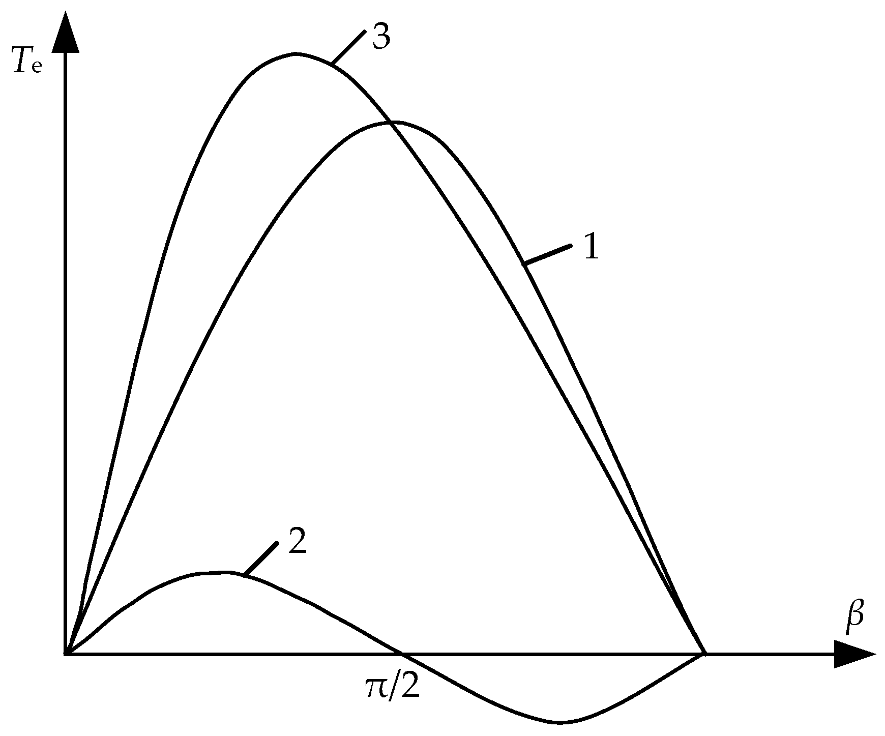
The angle between the stator current
Is and the d-axis is defined as the torque angle
β, as shown in
Figure 4.
The current components on the d-axis and q-axis can be expressed as
and
. Hence,
where
is the excitation torque generated by the interaction of the stator and rotor currents; and
is the reluctance torque caused by the unequal reluctances on the d-axis and q-axis. According to Equation (8), the relationship between torques and
β is shown in
Figure 4.
From
Figure 5, when the torque angle is between 0 and π/2, that is, the current vector is in the first quadrant of the dq coordinate system, the total torque can be maximized. Hence, the torque angle can be adjusted to make full use of the reluctance torque, which can improve the output torque.
4.2. RFOC
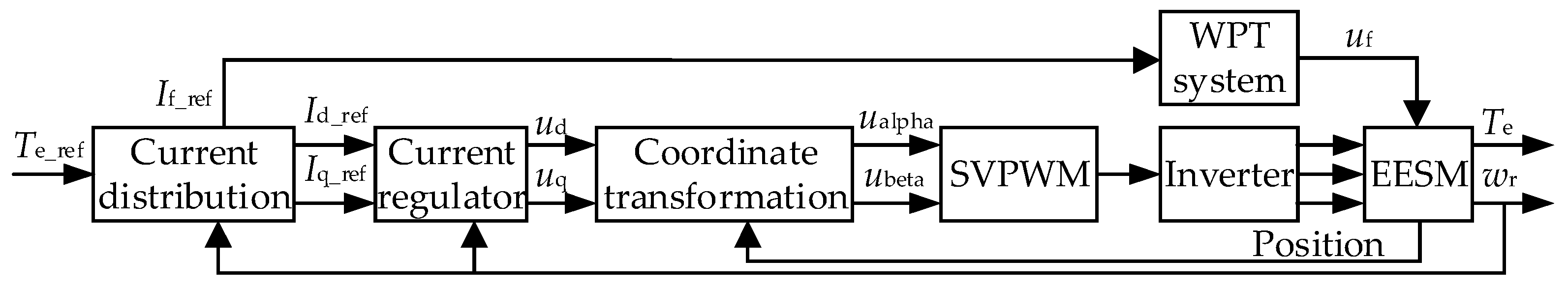
According to Equation (7), the total torque is determined by the stator and rotor currents. The RFOC can control the motor output torque by controlling the stator and rotor currents. The RFOC system of EESM is shown in
Figure 6.
The current distribution module determines the distribution law of the stator and rotor currents according to the command torque. The current regulator calculates the command voltage according to the command current and the actual current. The coordinate transformation of the command voltage is applied to the space vector pulse width modulation (SVPWM) module. Then the control signal of the inverter is obtained and the control of EESM is realized.
4.3. Stator Current Distribution Strategy
The stator current distribution must be within the current limit circle:
The voltage equation is mainly restricted at high speed, so the resistance voltage drop is ignored. Substituting Equation (4) into the upper equation, Equation (10) can be converted to the voltage limit ellipse:
Hence, the voltage limit equation is an ellipse whose center is , the long axis is , and the short axis is .
4.3.1. Maximum Torque per Ampere (MTPA) Control at Low Speed
Equation (8) can be written as
where
When
Te takes the maximum value:
The current components on d-axis and q-axis are
From Equations (17) and (18)
Equation (19) is the MTPA curve, which is essentially the set of tangent points of the current circle and the equal torque curve.
4.3.2. Maximum Torque Control under Voltage Limitation
When the motor has only a voltage limit and no current limit, the maximum torque per voltage (MTPV) is required. The Lagrange multiplier method is used here. The optimization function is set to be
From the first equation in Equation (21),
Substituting from Equation (22) into the second equation in Equation (21),
Substituting from Equation (23) into Equation (11),
From Equations (23) and (25), iq can be solved, and then the maximum torque control curve under voltage limitation can be obtained.
4.3.3. Stator Current Distribution Strategy
The rotor excitation current is controlled to a constant value, and the stator current is controlled according to different speeds. The MTPA strategy is used at low speed, and the MTPV strategy is used at high speed. The rotor excitation current is often not very large. Thus, the center point of the voltage limit ellipse is considered to be in the current limit circle. The relationship between voltage limit ellipse, current limit circle, MTPA curve, and MTPV curve is shown in
Figure 7.
The rotor excitation current is controlled to a constant value. At different speeds, the stator current can be controlled as follows.
At low speed, the stator current is distributed according to the MTPA strategy. According to the required torque, the command current is controlled on the MTPA curve.
As the motor speed increases, the voltage limit ellipse continues to shrink. When the speed is reached, the voltage limit ellipse touches the command current A1. Due to the inverter voltage limitation, the motor speed cannot continue to rise.
To increase the motor speed, the command current is adjusted leftward from the A1 point along the current limit circle until the current distribution point reaches the A2 point on the MTPV curve. In this process, the motor speed increases and the torque decreases.
The above is a method of current distribution, which runs in the whole speed range.
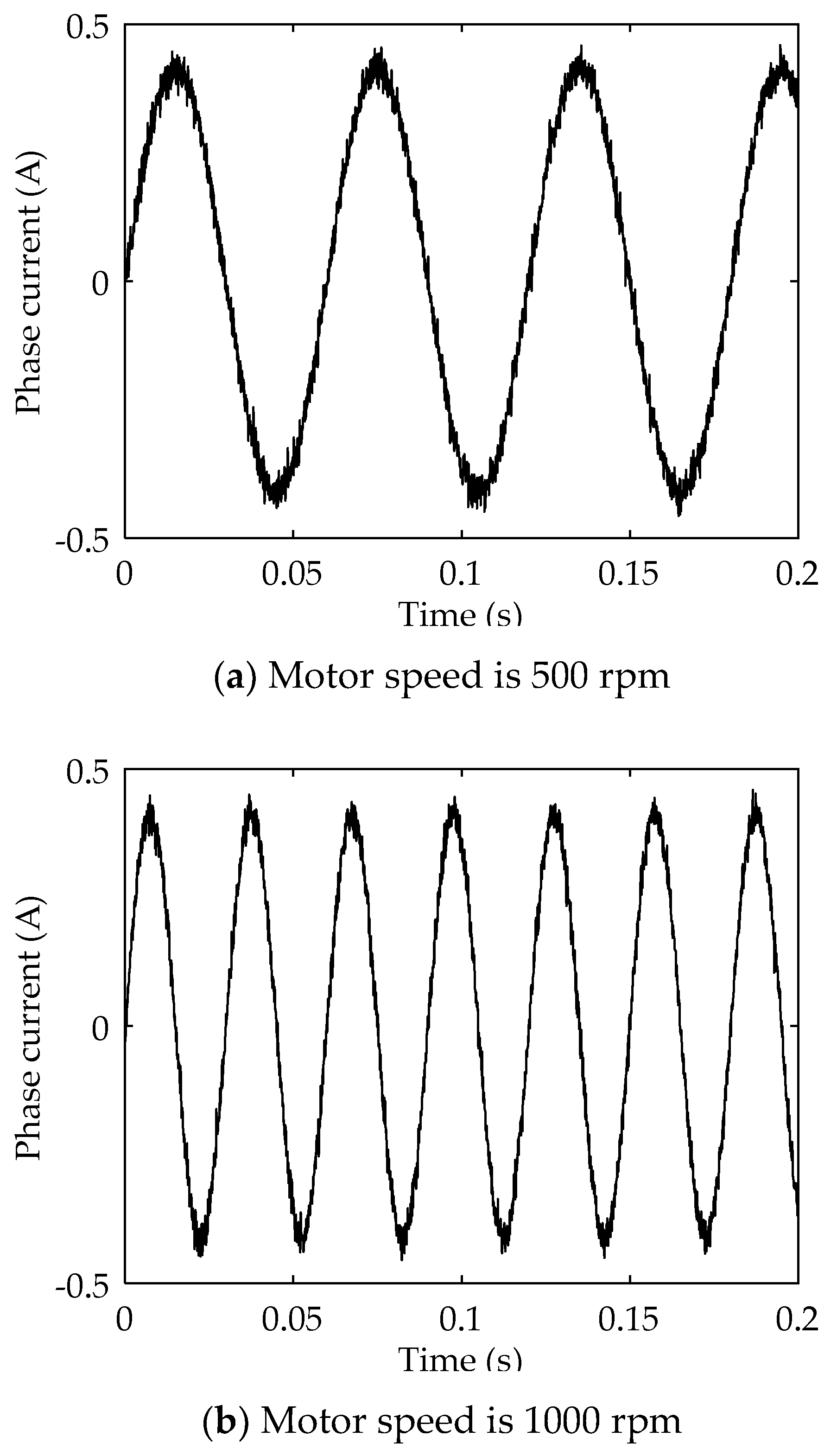
A simulation model of the RW-EESM was modeled in Matlab/Simscape and controlled by the above RFOC method. Under the no-load condition, the speed closed-loop control simulation was carried out. When the motor speed was 500 rpm and 1000 rpm, the phase currents were obtained, as shown in
Figure 8a,b, respectively.
5. Prototype Verification Test
Based on the theoretical analysis, a prototype was made. Furthermore, a test on the RW-EESM was carried out. The main components in the circuit and their parameters are shown in
Table 1. The test results are shown in
Figure 9 and
Figure 10.
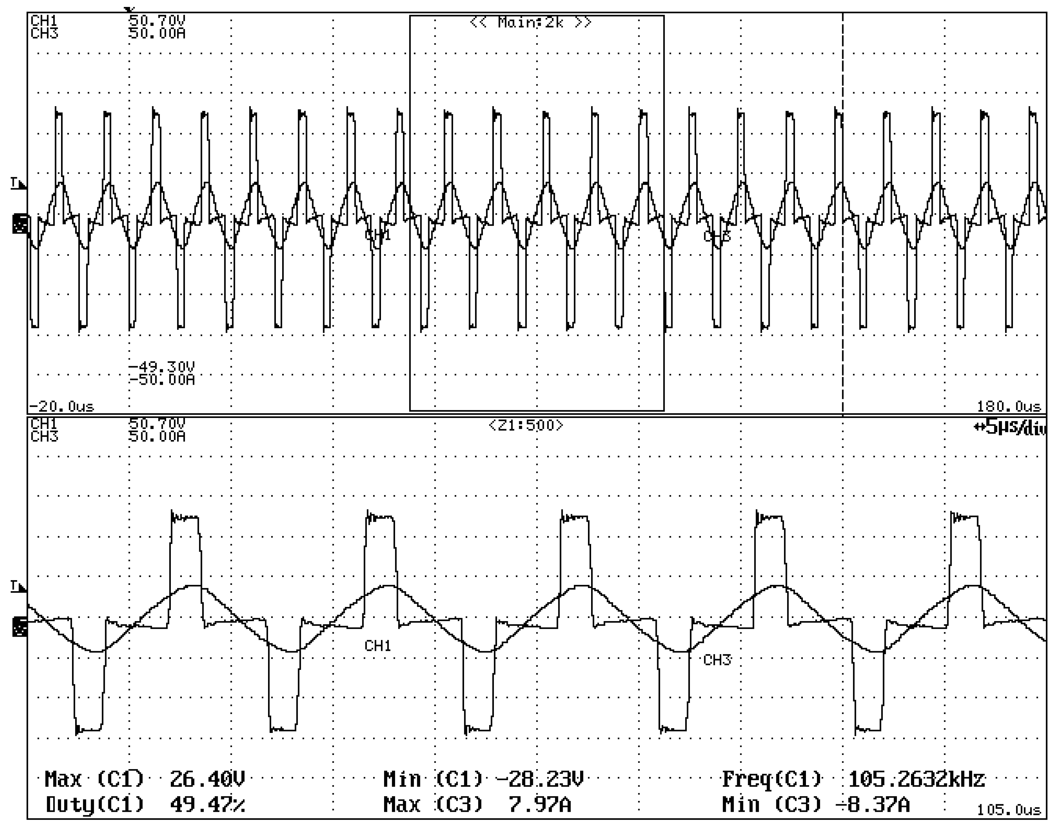
In the test, the resonant frequency was about 105 kHz, which was higher than the design value 100 kHz. Due to the attenuation of capacitance at high frequency, the resonant frequency was higher.
Figure 9 shows the relationship between excitation voltage and current on the primary side. Furthermore, the two phases were the same.
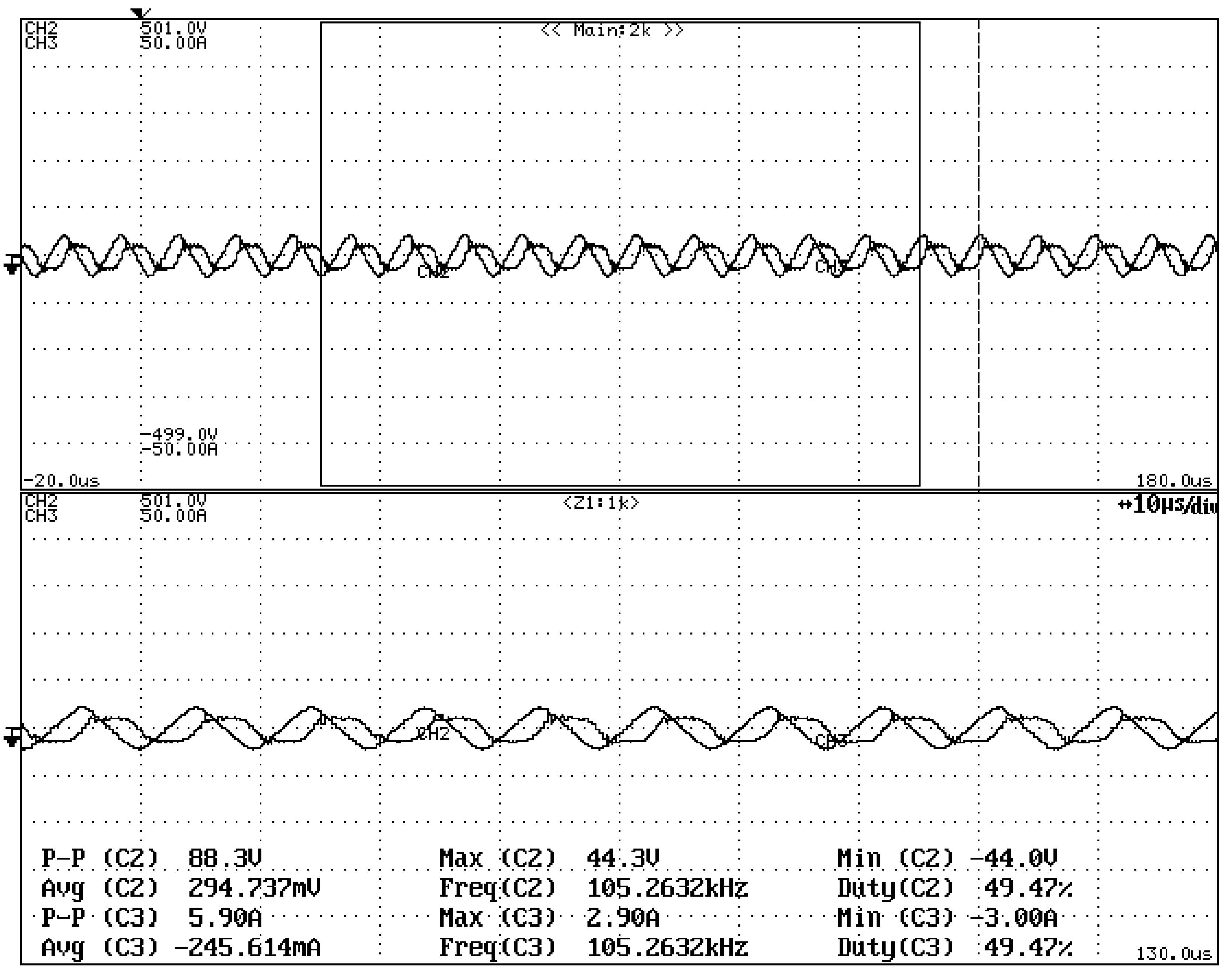
Figure 10 shows the relationship between resonant capacitor voltage and current on the secondary side. Furthermore, the phase difference was 90 degrees. The voltage received at the load side was a stable DC voltage. The test results agreed with the theory.
On the basis of an EESM prototype, an MRC-WPT system was used to realize the rotor resonant wireless excitation. The primary coil was fixed to the stator. The secondary coil and the rectifier filter circuit were mounted on the rotor and rotated along with the rotor. The RW-EESM prototype is shown in
Figure 11. The rotor resonant wireless excitation system of EESM and the RFOC of RW-EESM were tested and verified.
In the test, the rotor excitation was realized by the MRC-WPT system. Under no-load conditions, the motor was controlled by the RFOC approach. The phase current and the rotor position were recorded. The test results are shown in
Figure 12 and
Figure 13.
In the test, the motor ran smoothly, and the speed was stable at about 85 rpm. The sine of the phase currents was good. The results showed that the wireless excitation scheme of EESM was feasible, and the RFOC of RW-EESM motor proposed in this paper was reasonable.
6. Conclusions
Based on the principle of MRC-WPT, a rotor resonant wireless excitation system of EESM is designed. Furthermore, the RFOC of RW-EESM is studied. The results suggest the following conclusions.
(1) This paper applies the principle of MRC-WPT to the rotor excitation of EESM. A rotor resonant wireless excitation system of EESM is designed. The test results show that the wireless excitation system of EESM is feasible. The new RW-EESM is practical.
(2) By modeling the EESM, exploring the RFOC method, and analyzing the stator current distribution strategy, a control system of RW-EESM is established. Finally, the test on the RW-EESM prototype is carried out. Furthermore, the motor can run stably at no-load. The test results show that the RFOC of RW-EESM proposed in this paper is reasonable.
Author Contributions
Conceptualization, Z.Z.; methodology, Y.B.; software, C.H.; validation, Y.B. and Y.Q.; formal analysis, Y.B. and C.H.; writing—original draft preparation, Y.B.; writing—review and editing, Y.B.; funding acquisition, Z.Z.
Funding
This research was funded by the National Natural Science Foundation of China (Grant No. 51575392).
Conflicts of Interest
The authors declare no conflict of interest.
References
- Zhang, F.; Li, Y.; Wang, X. The design and FEA of brushless doubly-fed machine with hybrid rotor. In Proceedings of the 2009 International Conference on Applied Superconductivity and Electromagnetic Devices, ASEMD 2009, Chengdu, China, 25–27 September 2009; IEEE: Piscataway, NJ, USA, 2009. 5306627. pp. 324–327. [Google Scholar]
- Xia, Y.; Huang, S. Influence of field current pulsation on no-load voltage waveform of armature windings. Electr. Mach. Contrl. 2012, 16, 21–25. [Google Scholar]
- Liu, Y.; Pehrman, D.; Lykartsis, O.; Tang, J.; Liu, T. High frequency exciter of electrically excited synchronous motors for vehicle applications. In Proceedings of the 2016 22nd International Conference on Electrical Machines, ICEM 2016, Lausanne, Switzerland, 4–7 September 2016; IEEE: Piscataway, NJ, USA, 2016. 7732554. pp. 378–383. [Google Scholar]
- Tang, J.; Liu, Y. Design and Experimental Verification of a 48 v 20 kW Electrically Excited Synchronous Machine for Mild Hybrid Vehicles. In Proceedings of the 2018 23rd International Conference on Electrical Machines, ICEM 2018, Alexandroupoli, Greece, 3–6 September 2018; IEEE: Piscataway, NJ, USA, 2018. 8507259. pp. 649–655. [Google Scholar]
- Tang, J.; Liu, Y.; Rastogi, Y.; Sharma, N.; Shukla, T. Study of Voltage Spikes and Temperature Rise in Power Module Based Integrated Converter for 48 V 20 kW Electrically Excited Synchronous Machines. In Proceedings of the 2018 IEEE Applied Power Electronics Conference and Exposition, APEC 2018, San Antonio, TX, USA, 4–8 March 2018; IEEE: Piscataway, NJ, USA, 2018. 8341011. pp. 210–217. [Google Scholar]
- Tang, J.; Liu, Y. Comparison of copper loss minimization and field current minimization for Electrically Excited Synchronous Motor in mild hybrid drives. In Proceedings of the 2017 19th European Conference on Power Electronics and Applications, EPE 2017 ECCE Europe, Warsaw, Poland, 11–14 September 2017; IEEE: Piscataway, NJ, USA, 2017. 8099352. pp. 1–10. [Google Scholar]
- Hu, K.; Deng, X.; He, F. Design and analysis of novel structural brushless electrically excited synchronous motor. Electr. Mach. Contrl. 2014, 18, 86–91. [Google Scholar]
- Ludois, D.C.; Hanson, K.; Reed, J.K. Capacitive power transfer for slip ring replacement in wound field synchronous machines. In Proceedings of the 2011 IEEE Energy Conversion Congress and Exposition, ECCE 2011, Phoenix, AZ, USA, 17–22 September 2011; IEEE: Piscataway, NJ, USA, 2011. 6063982. pp. 1664–1669. [Google Scholar]
- Ludois, D.C.; Reed, J.K.; Hanson, K. Capacitive Power Transfer for Rotor Field Current in Synchronous Machines. IEEE Trans. Power Electron. 2012, 27, 4638–4645. [Google Scholar] [CrossRef]
- Dai, J.; Hagen, S.; Ludois, D.C.; Brown, I.P. Synchronous Generator Brushless Field Excitation and Voltage Regulation via Capacitive Coupling through Journal Bearings. IEEE Trans. Ind. Appl. 2017, 53, 3317–3326. [Google Scholar] [CrossRef]
- Dai, J.; Hagen, S.; Ludois, D.C.; Brown, I.P. Synchronous generator field excitation via capacitive coupling through a journal bearing. In Proceedings of the 2016 IEEE Energy Conversion Congress and Exposition, ECCE 2016, Milwaukee, WI, USA, 18–22 September 2016; IEEE: Piscataway, NJ, USA, 2016. 7855488. pp. 1–8. [Google Scholar]
- Kurs, A.; Karalis, A.; Moffatt, R.; Joannopoulos, J.D.; Fisher, P.; Soljacic, M. Wireless power transfer via strongly coupled magnetic resonances. Science 2007, 317, 83–86. [Google Scholar] [CrossRef] [PubMed]
- Jiang, C.; Chau, K.T.; Ching, T.W.; Liu, C.; Han, W. Time-Division Multiplexing Wireless Power Transfer for Separately Excited DC Motor Drives. IEEE Trans. Magnetics 2017, 53, 1–5. [Google Scholar] [CrossRef]
- Ditze, S.; Endruschat, A.; Schriefer, T.; Rosskopf, A.; Heckel, T. Inductive power transfer system with a rotary transformer for contactless energy transfer on rotating applications. In Proceedings of the 2016 IEEE International Symposium on Circuits and Systems, ISCAS 2016, Montreal, QC, Canada, 22–25 May 2016; IEEE: Piscataway, NJ, USA, 2016. 7538876. pp. 1622–1625. [Google Scholar]
© 2019 by the authors. Licensee MDPI, Basel, Switzerland. This article is an open access article distributed under the terms and conditions of the Creative Commons Attribution (CC BY) license (http://creativecommons.org/licenses/by/4.0/).


